

Page 1

A8N-SLI
Premium
Motherboard
Page 2

E243 5
Revi s e d Edi t i o n V3
Febr u a r y 20 0 6
Copyright © 2006 ASUSTeK COMPUTER INC. All Rights Reserved.
No part of this manual, including the products and software described in it, may be reproduced,
transmitted, transcribed, stored in a retrieval system, or translated into any language in any form
or by any means, except documentation kept by the purchaser for backup purposes, without the
express written permission of ASUSTeK COMPUTER INC. (“ASUS”).
Product warranty or service will not be extended if: (1) the product is repaired, modified or
altered, unless such repair, modification of alteration is authorized in writing by ASUS; or (2)
the serial number of the product is defaced or missing.
ASUS PROVIDES THIS MANUAL “AS IS” WITHOUT WARRANTY OF ANY KIND, EITHER
EXPRESS OR IMPLIED, INCLUDING BUT NOT LIMITED TO THE IMPLIED WARRANTIES
OR CONDITIONS OF MERCHANTABILITY OR FITNESS FOR A PARTICULAR PURPOSE.
IN NO EVENT SHALL ASUS, ITS DIRECTORS, OFFICERS, EMPLOYEES OR AGENTS BE
LIABLE FOR ANY INDIRECT, SPECIAL, INCIDENTAL, OR CONSEQUENTIAL DAMAGES
(INCLUDING DAMAGES FOR LOSS OF PROFITS, LOSS OF BUSINESS, LOSS OF USE
OR DATA, INTERRUPTION OF BUSINESS AND THE LIKE), EVEN IF ASUS HAS BEEN
ADVISED OF THE POSSIBILITY OF SUCH DAMAGES ARISING FROM ANY DEFECT OR
ERROR IN THIS MANUAL OR PRODUCT.
SPECIFICATIONS AND INFORMATION CONTAINED IN THIS MANUAL ARE FURNISHED
FOR INFORMATIONAL USE ONLY, AND ARE SUBJECT TO CHANGE AT ANY TIME
WITHOUT NOTICE, AND SHOULD NOT BE CONSTRUED AS A COMMITMENT BY
ASUS. ASUS ASSUMES NO RESPONSIBILITY OR LIABILITY FOR ANY ERRORS OR
INACCURACIES THAT MAY APPEAR IN THIS MANUAL, INCLUDING THE PRODUCTS
AND SOFTWARE DESCRIBED IN IT.
Products and corporate names appearing in this manual may or may not be registered
trademarks or copyrights of their respective companies, and are used only for identification or
explanation and to the owners’ benefit, without intent to infringe.
ii
Page 3

Contents
Notices ...............................................................................................viii
Safety information .............................................................................. ix
About this guide ................................................................................... x
How this guide is organized ...................................................... x
Where to find more information .............................................. xi
Conventions used in this guide ................................................ xi
Typography ......................................................................................... xi
A8N-SLI Premium specifications summary ..........................................xii
Chapter 1: Product introduction
1.1 Welcome! .............................................................................. 1-1
1.2 Package contents ................................................................. 1-1
1.3 Special features .................................................................... 1-2
1.3.1 Product highlights ................................................... 1-2
1.3.2 ASUS Proactive features ........................................ 1-5
1.3.3 Innovative ASUS features ....................................... 1-6
Chapter 2: Hardware information
2.1 Before you proceed .............................................................. 2-1
2.2 Motherboard overview .......................................................... 2-2
2.2.1 Placement direction ................................................ 2-2
2.2.2 Screw holes ............................................................. 2-2
2.2.3 Motherboard layout ................................................ 2-3
2.2.4 Layout Contents ..................................................... 2-4
2.3 Central Processing Unit (CPU) .............................................. 2-6
2.3.1 Overview ................................................................. 2-6
2.3.2 Installling the CPU ................................................... 2-6
2.3.3 Installing the heatsink and fan ................................ 2-8
2.4 System memory .................................................................. 2-11
2.4.1 Overview ............................................................... 2-11
2.4.2 Memory Configurations ......................................... 2-11
2.4.3 Installing a DIMM ...................................................2-14
2.4.4 Removing a DIMM .................................................. 2-14
2.5 Expansion slots ................................................................... 2-15
2.5.1 Installing an expansion card .................................. 2-15
2.5.2 Configuring an expansion card .............................. 2-15
iii
Page 4
Contents
2.5.3 Interrupt assignments ........................................... 2-16
2.5.4 PCI slots ................................................................ 2-16
2.5.5 Two PCI Express x16 slots .................................... 2-17
2.5.6 PCI Express x1 slot ............................................... 2-17
2.5.7 Universal PCIe slot (PCI Express x4 slot) .............. 2-17
2.6 Jumpers .............................................................................. 2-18
2.7 Connectors .........................................................................2-19
2.7.1 Rear panel connectors .......................................... 2-19
2.7.2 Internal connectors ............................................... 2-21
Chapter 3: Powering up
3.1 Starting up for the first time ................................................ 3-1
3.2 Powering off the computer ................................................... 3-2
3.2.1 Using the OS shut down function ........................... 3-2
3.2.2 Using the dual function power switch ..................... 3-2
3.3 ASUS POST Reporter™ .......................................................... 3-3
3.3.1 Vocal POST messages ............................................. 3-3
3.3.2 Winbond Voice Editor ............................................. 3-5
Chapter 4: BIOS setup
4.1 Managing and updating your BIOS ........................................ 4-1
4.1.1 Creating a bootable floppy disk .............................. 4-1
4.1.2 Updating the BIOS ................................................... 4-2
4.1.3 Saving the current BIOS file .................................... 4-4
4.1.4 ASUS CrashFree BIOS 2 utility ................................ 4-5
4.1.5 ASUS EZ Flash utility ............................................... 4-7
4.1.6 ASUS Update utility ................................................ 4-8
4.2 BIOS setup program ............................................................ 4-11
4.2.1 BIOS menu screen ................................................. 4-12
4.2.2 Menu bar ............................................................... 4-12
4.2.3 Legend bar ............................................................ 4-13
4.2.4 Menu items ........................................................... 4-13
4.2.5 Sub-menu items .................................................... 4-13
4.2.6 Configuration fields ............................................... 4-13
4.2.8 General help .......................................................... 4-14
4.2.7 Pop-up window ...................................................... 4-14
iv
Page 5

Contents
4.3 Main menu ........................................................................... 4-15
4.3.1 System Time ........................................................ 4-15
4.3.2 System Date ........................................................ 4-15
4.3.3 Language ............................................................. 4-15
4.3.4 Legacy Diskette A ...............................................4-15
4.3.5 Primary and Secondary IDE Master/Slave ............. 4-16
4.3.5 First, Second, Third, Fourth SATA Master ............4-18
4.3.7 HDD SMART Monitoring ......................................... 4-19
4.3.8 Installed Memory ................................................... 4-19
4.4 Advanced menu .................................................................. 4-20
4.4.1 CPU Configuration ................................................. 4-20
4.4.2 PCIPnP ................................................................... 4-23
4.4.3 Onboard Devices Configuration ............................. 4-24
4.4.4 SLI Configuration ................................................... 4-29
4.4.5 JumperFree Configuration ..................................... 4-30
4.4.6 LAN Cable Status .................................................. 4-32
4.4.7 PEG Link Mode ....................................................... 4-33
4.4.8 Speech Configuration ............................................ 4-34
4.4.9 Instant Music ......................................................... 4-34
4.5 Power menu ........................................................................ 4-35
4.5.1 ACPI Suspend Type ............................................... 4-35
4.5.2 ACPI APIC Support ................................................ 4-35
4.5.3 APM Configuration ................................................4-36
4.5.4 Hardware Monitor .................................................. 4-38
4.6 Boot menu .......................................................................... 4-40
4.6.1 Boot Device Priority .............................................. 4-40
4.6.3 Hard Disk Drives .................................................... 4-41
4.6.2 Removable Drives .................................................. 4-41
4.6.4 CDROM Drives ....................................................... 4-42
4.6.5 Boot Settings Configuration ................................4-42
4.6.6 Security ................................................................. 4-44
4.7 Exit menu ............................................................................ 4-46
Chapter 5: Software support
5.1 Installing an operating system .............................................. 5-1
v
Page 6

Contents
5.2 Support CD information ........................................................ 5-1
5.2.1 Running the support CD .......................................... 5-1
5.2.2 Drivers menu ........................................................... 5-2
5.2.3 Utilities menu .......................................................... 5-3
5.2.4 Manuals menu ......................................................... 5-5
5.2.5 ASUS Contact information ...................................... 5-6
5.2.6 Other information ................................................... 5-6
5.4 Software information ............................................................ 5-9
5.4.1 ASUS MyLogo2™ ..................................................... 5-9
5.4.2 AI NET 2 ................................................................ 5-11
Using the Virtual Cable Tester™ ........................... 5-11
5.4.3 Audio configurations ............................................. 5-12
5.4.4 Using the NVIDIA® Firewall™ .................................. 5-18
5.5 RAID configurations ............................................................ 5-21
5.5.1 Installing hard disks ............................................... 5-22
5.5.2 NVIDIA® RAID configurations ................................. 5-23
5.5.3 Silicon Image RAID configurations ......................... 5-30
5.6 Creating a RAID driver disk ................................................. 5-40
5.7 Cool ʻnʼ Quiet!™ Technology ............................................... 5-41
5.7.1 Enabling Cool ʻnʼ Quiet!™ Technology ................... 5-41
5.7.2 Launching the Cool ʻnʼ Quiet!™ software .............. 5-42
5.8 Using the NVIDIA® nTune™ utility ....................................... 5-43
5.8.1 Managing your nForce™ system ............................ 5-43
5.8.2 Clock control ......................................................... 5-44
5.8.3 Voltage/Fan control .............................................. 5-44
5.8.4 Information ........................................................... 5-45
5.8.5 Other options ........................................................ 5-45
5.9 Using the ASUS AI Selector utility ...................................... 5-46
5.9.1 Launching the ASUS AI Selector ........................... 5-46
5.9.2 Using the SLI mode ............................................... 5-47
Chapter 6: SLI™ technology support
6.1 Overview ............................................................................... 6-1
6.1.1 Requirements .......................................................... 6-1
6.1.2 ASUS Certified SLI Graphics cards .......................... 6-1
vi
Page 7

6.2 Dual graphics card setup ...................................................... 6-3
6.2.1 Installing SLI-ready graphics cards .......................... 6-3
6.2.2 Setting the SLI mode in BIOS .................................. 6-7
6.2.3 Installing the device drivers .................................... 6-7
6.2.4 Enabling the multi-GPU feature in Windows ............ 6-7
Appendix
A.1 Using the SATA extension module ....................................... A-1
A.1.1 Installing the 2-port SATA extension module ......... A-1
A.1.1 Installing SATA hard drives ..................................... A-2
vii
Page 8
Notices
Fed er al Co mm un ica ti on s C om mi ssi on S tat em en t
This device complies with Part 15 of the FCC Rules. Operation is subject to
the following two conditions:
•
This device may not cause harmful interference, and
•
This device must accept any interference received including
interference that may cause undesired operation.
This equipment has been tested and found to comply with the limits for a
Class B digital device, pursuant to Part 15 of the FCC Rules. These limits
are designed to provide reasonable protection against harmful interference
in a residential installation. This equipment generates, uses and can radiate
radio frequency energy and, if not installed and used in accordance with
manufacturerʼs instructions, may cause harmful interference to radio
communications. However, there is no guarantee that interference will
not occur in a particular installation. If this equipment does cause harmful
interference to radio or television reception, which can be determined by
turning the equipment off and on, the user is encouraged to try to correct
the interference by one or more of the following measures:
•
Reorient or relocate the receiving antenna.
•
Increase the separation between the equipment and receiver.
•
Connect the equipment to an outlet on a circuit different from that to
which the receiver is connected.
•
Consult the dealer or an experienced radio/TV technician for help.
The use of shielded cables for connection of the monitor to the graphics
card is required to assure compliance with FCC regulations. Changes
or modifications to this unit not expressly approved by the party
responsible for compliance could void the userʼs authority to operate
this equipment.
Can ad ia n D ep ar tme nt o f C om mu nic at io ns St at eme nt
This digital apparatus does not exceed the Class B limits for radio noise
emissions from digital apparatus set out in the Radio Interference
Regulations of the Canadian Department of Communications.
This class B digital apparatus complies with Canadian
ICES-003.
viii
Page 9
Safety information
Ele ct ri cal s af ety
•
To prevent electrical shock hazard, disconnect the power cable from
the electrical outlet before relocating the system.
•
When adding or removing devices to or from the system, ensure that
the power cables for the devices are unplugged before the signal cables
are connected. If possible, disconnect all power cables from the existing
system before you add a device.
•
Before connecting or removing signal cables from the motherboard,
ensure that all power cables are unplugged.
•
Seek professional assistance before using an adapter or extension cord.
These devices could interrupt the grounding circuit.
•
Make sure that your power supply is set to the correct voltage in your
area. If you are not sure about the voltage of the electrical outlet you
are using, contact your local power company.
•
If the power supply is broken, do not try to fix it by yourself. Contact a
qualified service technician or your retailer.
Ope ra ti on sa fe ty
•
Before installing the motherboard and adding devices on it, carefully
read all the manuals that came with the package.
•
Before using the product, make sure all cables are correctly connected
and the power cables are not damaged. If you detect any damage,
contact your dealer immediately.
•
To avoid short circuits, keep paper clips, screws, and staples away from
connectors, slots, sockets and circuitry.
•
Avoid dust, humidity, and temperature extremes. Do not place the
product in any area where it may become wet.
•
Place the product on a stable surface.
•
If you encounter technical problems with the product, contact a
qualified service technician or your retailer.
The symbol of the crossed out wheeled bin indicates that the product
(electrical and electronic equipment) should not be placed in municipal
waste. Check local regulations for disposal of electronic products.
ix
Page 10
About this guide
This user guide contains the information you need when installing and
configuring the motherboard.
How t hi s g ui de is o rg ani ze d
This manual contains the following parts:
• Chap t e r 1: P r o duct i n trod u c t ion
This chapter describes the features of the motherboard and the new
technology it supports.
• Chap t e r 2: H a r dwar e i nfor m a t ion
This chapter lists the hardware setup procedures that you have to
perform when installing system components. It includes description of
the switches, jumpers, and connectors on the motherboard.
• Chap t e r 3: P o w erin g u p
This chapter describes the power up sequence, the vocal POST
messages, and ways of shutting down the system.
• Chap t e r 4: B I O S se t u p
This chapter tells how to change system settings through the BIOS
Setup menus. Detailed descriptions of the BIOS parameters are also
provided.
• Chap t e r 5: S o f twar e s uppo r t
This chapter describes the contents of the support CD that comes
with the motherboard package.
• Chap t e r 6: N V I DIA® SLI ™ t echn o l o gy s u p p ort
This chapter tells how to install SLI-ready PCI Express graphics cards.
• Appe n d i x: I n s t alla t i o n op t i o ns
This appendix describes how to install optional accessories to your
motherboard.
x
Page 11
Whe re t o f in d mor e in for ma ti on
Refer to the following sources for additional information and for product
and software updates.
1. A S U S we b s i tes
The ASUS website provides updated information on ASUS hardware
and software products. Refer to the ASUS contact information.
2. O p t iona l d ocum e n t atio n
Your product package may include optional documentation, such as
warranty flyers, that may have been added by your dealer. These
documents are not part of the standard package.
Con ve nt ion s us ed in t his g ui de
To make sure that you perform certain tasks properly, take note of the
following symbols used throughout this manual.
DANGER/WARNING: Information to prevent injury to yourself
when trying to complete a task.
CAUTION: Information to prevent damage to the components
when trying to complete a task.
IMPORTANT: Instructions that you MUST follow to complete a
task.
NOTE: Tips and additional information to help you complete a
task.
Typography
Bold text Indicates a menu or an item to select
Italics
Used to emphasize a word or a phrase
<Key> Keys enclosed in the less-than and greater-than sign means
that you must press the enclosed key
Example: <Enter> means that you must press the Enter or
Return key
<Key1>+<Key2>+<Key3> If you must press two or more keys simultaneously, the
key names are linked with a plus sign (+)
Example: <Ctrl>+<Alt>+<D>
Command
then supply the required item or value enclosed in
brackets
Example: At the DOS prompt, type the command line:
awdflash A8NSLI.ROM
Means that you must type the command exactly as shown,
xi
Page 12
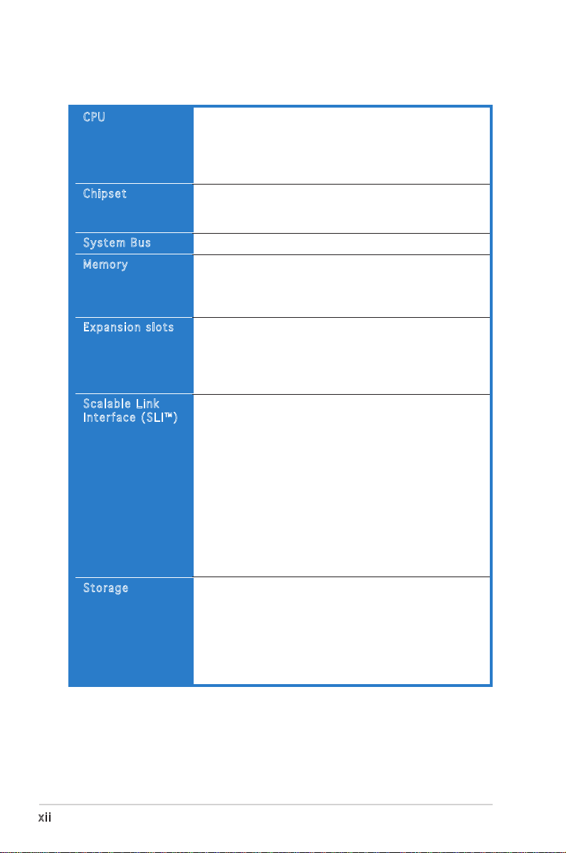
A8N-SLI Premium specifications summary
CPU
Chipset
System Bus
Memory
Expansion slots
Scalable Link
Interface (SLI™)
Storage
Socket 939 for AMD Athlon™ 64FX/AMD Athlon™ 64
processor
Supports AMD 64 architecture that enables simultaneous
32-bit and 64-bit architecture
Supports AMD® Cool ʻnʼ Quiet! Technology
NVIDIA® nForce™ 4 SLI
Supports NVIDIA® Scalable Link Interface™ (SLI)
technology
1600/2000 MT per second
Dual-channel memory architecture
4 x 184-pin DIMM sockets support ECC/non-ECC
unbufferred 400/333/266 MHz DDR memory modules
Supports up to 4 GB system memory
2 x PCI Express x16 slots with Scalable Link Interface
(SLI™) support
1 x PCI Express x1 slot
1 x PCI Express x4 slot running at 1 GB/s bandwidth
3 x PCI slots
SLI™ mode supports:
- 2 x identical SLI™-ready PCI Express x16 graphics
cards
(Note: In SLI mode, the PCI Express x16 slots work at the
bandwidth of PCI Express x8. The combined bandwidth of
these maintain the bandwidth of PCI Express x16.)
Single card mode supports (default):
- 1 x any PCI Express x16 graphics card on the first
slot (blue)
ASUS AI Selector
ASUS EZ Plug™
ASUS PEG Link for dual PCI Express graphics cards
ASUS Two-slot thermal design
NVIDIA® nForce™ 4 SLI chipset supports:
- 2 x Ultra DMA 133/100/66/33
- 4 x Serial ATA II devices
- RAID 0, RAID 1, RAID 0+1, and JBOD
Silicon Image 3114R RAID controller supports:
- 4 x Serial ATA with RAID 0, RAID 1, RAID 0+1, and
RAID 5 configuration
xii
(continued on the next page)
Page 13
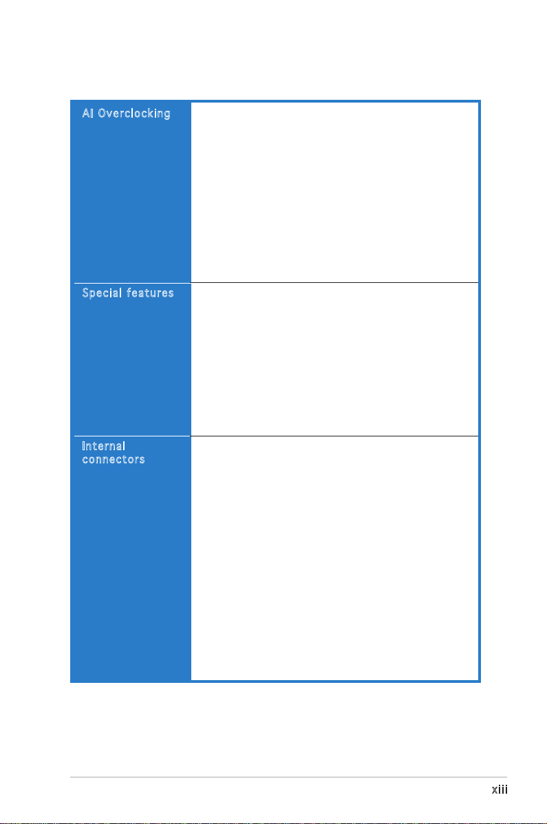
A8N-SLI Premium specifications summary
AI Overclocking
Special features
Internal
connectors
AI NOS™ (Non-Delay Overclocking System)
ASUS AI Overclocking (Intelligent CPU frequency tuner)
ASUS PEG Link for single/dual graphics card
Fixed PCI Express/PCI/SATA frequencies
ASUS C.P.R. (CPU Parameter Recall)
Precision Tweaker supports:
- DIMM voltage: 9-step DRAM voltage control
- Core voltage: Adjustable CPU voltage at 0.0125
increment
- PCI Express Frequency: Allows 1MHz increment from
100MHz to 200MHz
- Stepless Frequency Selection(SFS) allows 1MHz
increment from 200 MHz to 400 MHz
ASUS AI Cool-Pipe
ASUS AI Selector
ASUS Post Reporter™
ASUS EZFlash
ASUS Q-Fan
ASUS CrashFree BIOS 2
ASUS Multi-language BIOS
ASUS MyLogo2
ASUS Instant Music
ASUS SLI Warning LED
ASUS EZ Plug
1 x Floppy disk drive connector
2 x IDE connectors
8 x Serial ATA connectors
1 x CPU fan connector
1 x Power fan connector
2 x Chassis fan connector
1 x Chipset fan connector
1 x Serial port connector (COM port)
1 x 24-pin ATX power connector
1 x 4-pin ATX 12 V power connector
1 x 4-pin ASUS EZ Plug™ connector
3 x USB 2.0 connectors for 6 additional USB 2.0 ports
1 x Internal audio connectors (CD\AUX)
1 x IEEE 1394 connector
1 x GAME/MIDI connector
1 x Chassis intrusion connector
1 x Front panel audio connector
System panel connector
(continued on the next page)
xiii
Page 14
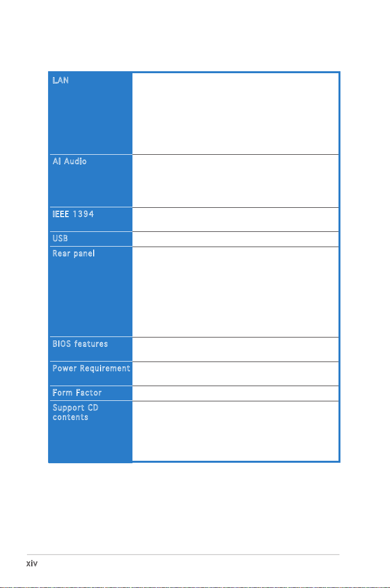
A8N-SLI Premium specifications summary
LAN
AI Audio
IEEE 1394
USB
Rear panel
BIOS features
Power Requirement
Form Factor
Support CD
contents
NVIDIA® nForce™ 4 built-in Gigabit MAC with external
Marvell® PHY supports:
- NV ActiveArmor
- NV Firewall
- AI NET2
Marvell® 88E8001 PCI Gigabit LAN controller supports:
- Marvell® Virtual Cable Tester technology
- AI NET2
Realtek® ALC850 8-channel CODEC
1 x Coaxial S/PDIF out port
1 x Optical S/PDIF out port
Supports Universal Audio Jack (UAJ®) Technology
Supports Audio Sensing and Enumeration Technology
T1 1394a controller supports:
- 2 x IEEE 1394 connector
Supports up to 10 USB 2.0 ports
1 x Parallel port
1 x IEEE 1394 port
2 x LAN (RJ-45) port
4 x USB 2.0 ports
1 x Optical S/PDIF out port
1 x Coaxial S/PDIF out port
1 x PS/2 keyboard port
1 x PS/2 mouse port
8-channel audio ports
4 Mb Flash ROM, Phoenix-Award BIOS, PnP, DMI2.0,
WfM2.0, SM BIOS 2.3
ATX power supply (with 24-pin and 4-pin 12 V plugs)
ATX 12 V 2.0 compliant
ATX form factor: 12 in x 9.6 in (30.5 cm x 24.4 cm)
Device drivers
ASUS PC Probe
ASUS Live Update utility
ASUS CoolʼnʼQuiet! utility
Anti-virus utility (OEM version)
NVIDIA® nTune™ utility
*Specifications are subject to change without notice.
xiv
Page 15

This chapter describes the motherboard
features and the new technologies
it supports.
introduction
Product
1
Page 16

Chapter summary
1.1 Welcome! .............................................................................. 1-1
1.2 Package contents ................................................................. 1-1
1.3 Special features .................................................................... 1-2
ASUS A8N-SLI Premium
Page 17
1.1 Welcome!
Than k y ou f o r buyi n g an A S U S® A8N - S L I Pr e m i um m o t h erbo a r d !
The motherboard delivers a host of new features and latest technologies,
making it another standout in the long line of ASUS quality motherboards!
Before you start installing the motherboard, and hardware devices on it,
check the items in your package with the list below.
1.2 Package contents
Check your motherboard package for the following items.
Motherboard ASUS A8N-SLI Premium motherboard
I/O modules Serial ATA 2-port extension module
IEEE1394 (1 port) module
USB 2.0 2-port module
USB 2.0 + GAME port module
Cables 8 x Serial ATA signal cables
Serial ATA power cable with dual plugs
Ultra DMA/133 cable
40-conductor IDE cable
Floppy disk drive cable
COM cable
Accessories I/O shield
SLI™ flexible cable
Application CDs ASUS motherboard support CD
InterVideo® WinDVD Suite® (retail box only)
Documentation User guide
If any of the above items is damaged or missing, contact your retailer.
ASUS A8N-SLI Premium 1-1
Page 18
1.3 Special features
1.3 .1 Pro du ct hi gh li ght s
Lat e st pro c es s or t ec h nol o gy
The AMD Athlon™ 64FX and Athlon™ 64 desktop processors are based
on AMDʼs 64-bit and 32-bit architecture, which represents the landmark
introduction of the industryʼs first x86-64 technology. These processors
provide a dramatic leap forward in compatibility, performance, investment
protection, and reduced total cost of ownership and development.
See page 2-6.
Sca l ab l e L i nk Int e rf a ce ( SL I ™) t ec h nol o gy
The NVIDIA® nForce4® Scalable Link Interface (SLI™) technology allows two
graphics processing units (GPUs) in a single system. This technology takes
advantage of the PCI Express™ bus architecture and features intelligent
hardware and software solutions that allows multiple GPUs to work
together and achieve exceptional graphics performance. See Chapter 6 for
details.
Bui l t- i n N V Fi r ewa l l™ and NV A cti v eA r mor ™
The NVIDIA® Firewall™ (NVFirewall™) is an easy-to-use high-performance
desktop firewall application that protects your system from intruders.
Integrated into the NVIDIA® nForce4® SLI™ chipset with the NVIDIA® Gigabit
Ethernet, it provides advanced anti-computer-hacking technologies, remote
management capabilities, and a user-friendly setup wizard that improves
overall system security.
Enhancing your network security is the NVIDIA® ActiveArmor™
(NV ActiveArmor™) engine that provides advanced data packet inspection.
This innovative technology ensures that only safe data packets are passed
on the network. It boosts overall system performance by offloading the
CPU from the rigorous task of filtering data packets. See page 5-18 for
details.
AMD Co o l ʻ n ʼ Q uie t !™ Tec h no l ogy
The motherboard supports the AMD Cool ʻnʼ Quiet!™ Technology that
dynamically and automatically changes the CPU speed, voltage and amount
of power depending on the task the CPU performs. See pages 4-20 and
5-41.
1-2 Chapter 1: Product introduction
Page 19
Hyp e rT r ans p or t ™ T e ch n olo g y
HyperTransport™ Technology is a high-speed, low latency, point-to-point
link designed to increase the communication speed between integrated
circuits in computers, networking and telecommunicatons equipment up to
48 times faster than other existing technologies.
Dua l C h ann e l D DR m em o ry s up p ort
Employing the Double Data Rate (DDR) memory technology,
the motherboard supports up to 4GB of system memory using
DDR400/333/266 DIMMs. The ultra-fast 400MHz memory bus delivers the
required bandwidth for the latest 3D graphics, multimedia, and Internet
applications. See page 2-11.
Ser i al ATA II tec h no l ogy
The motherboard supports the next-generation Serial ATA 3Gb/s
technology through the Serial ATA interfaces and the NVIDIA® SLI™ chipset.
The SATA 3Gb/s specification provides twice the bandwidth of the current
Serial ATA products with a host of new features including Native Command
Queuing (NCQ), Power Management (PM) Implementation Algorithm, and
Hot Swap. Additionally, Serial ATA allows thinner, more flexible cables with
lower pin count, and reduced voltage requirement. See pages 2-22 and
2-23.
Dua l R A ID s ol u tio n
Onboard RAID controllers provide the motherboard with dual-RAID
functionality that allows you to select the best RAID solution using IDE or
Serial ATA devices.
The NVIDIA® nForce4® SLI™ allows RAID 0, RAID 1, RAID 0+1 and JBOD
configuration for four SATA connectors or two PATA connectors. See
pages 2-22 and 5-23 for details.
The Sil3114R controller supports four additional SATA connectors and
allows RAID 0, RAID 1, RAID 0+1, and a software patch to support a
bootable RAID 5 configuration. See pages 2-23 and 5-30 for details.
PCI Ex p res s ™ i nte r fa c e
The motherboard fully supports PCI Express, the latest I/O interconnect
technology that speeds up the PCI bus. PCI Express features point-to-point
serial interconnections between devices and allows higher clockspeeds by
carrying data in packets. This high speed interface is software compatible
with existing PCI specifications. See page 2-17 for details.
ASUS A8N-SLI Premium 1-3
Page 20
S/P D IF dig i ta l so u nd rea d y
The motherboard supports the S/PDIF Out function through the S/PDIF
interfaces on the rear panel. The S/PDIF technology turns your computer
into a high-end entertainment system with digital connectivity to powerful
audio and speaker systems. See page 2-19 for details.
IEE E 1 3 94a sup p or t
The IEEE 1394a interface provides high-speed and flexible PC connectivity
to a wide range of peripherals and devices compliant to the IEEE 1394a
standard. The IEEE 1394a interface allows up to 400 Mbps transfer rates
through simple, low-cost, high-bandwidth asynchronous (real-time) data
interfacing between computers, peripherals, and consumer electronic
devices such as camcorders, VCRs, printers, TVs, and digital cameras. See
pages 2-19 and 2-28 for details.
USB 2.0 te c hno log y
The motherboard implements the Universal Serial Bus (USB) 2.0
specification, dramatically increasing the connection speed from the
12 Mbps bandwidth on USB 1.1 to a fast 480 Mbps on USB 2.0. USB 2.0 is
backward compatible with USB 1.1. See page 2-19 and 2-25 for details.
Tem p er a tur e , f an, an d vo l ta g e m o ni t ori n g
The CPU temperature is monitored by the ASIC (integrated in the Winbond
Super I/O) to prevent overheating and damage. The system fan rotations
per minute (RPM) is monitored for timely failure detection. The ASIC
monitors the voltage levels to ensure stable supply of current for critical
components. See section “4.5.4 Hardware Monitor” on page 4-38.
1-4 Chapter 1: Product introduction
Page 21
1.3 .2 ASU S Pr oac ti ve fe at ur es
AI N OS ™ (N o n- D ela y O v erc l oc k ing Sy s tem )
ASUS Non-delay Overclocking System™ (NOS) is a technology that
auto-detects the CPU loading and dynamically overclocks the CPU speed
only when needed. See page 4-30 for details.
AI C oo l -Pi p e
ASUS AI Cool-Pipe is a unique heat pipe design that dissipates heat
away from the chipset. This device significantly lowers overall system
temperature for a quiet and stable system performance.
Pre c is i on T we a ker
Designed for overclocking aficionados, this feature allows you to fine tune
the CPU/memory voltage and gradually increase the Front Side Bus (FSB)
and PCI Express frequency to achieve maximum system performance.
AI N ET 2
AI NET 2 is a BIOS-based diagnostic tool that detects and reports
Ethernet cable faults and shorts. With this utility, you can easily monitor
the condition of the Ethernet cable(s) connected to the LAN (RJ-45)
port(s). During the bootup process, AI NET 2 immediately diagnoses the
LAN cable(s) and reports shorts and faults up to 100 meters at 1 meter
accuracy. See pages 4-32 and 5-11 for details.
AI A ud i o t e ch n olo g y
The motherboard supports 8-channel audio through the onboard ALC850
CODEC with 16-bit DAC, a stereo 16-bit ADC, and an AC97 2.3 compatible
multi-channel audio designed for PC multimedia systems. It also provides
Jack-Sensing function, S/PDIF out support, interrupt capability and includes
the Realtek® proprietary UAJ® (Universal Audio Jack) technology. See pages
2-19, 2-20 and 5-12 for details.
ASUS A8N-SLI Premium 1-5
Page 22
1.3 .3 Inn ov at ive A SU S f ea tu res
ASU S A I Se l ec t or
The AI Selector allows you to set the video card mode of your system. This
utility works when you have two graphics cards installed in your system.
See page 5-46 for details.
ASU S E Z Pl u g™
This patented ASUS technology is a 4-pin auxiliary +12V connector that
is designed to maintain the voltage integrity of your system. This plug
guarantees adequate supply of power to the motherboard and other
installed peripherals. See page 6-5 for illustration.
ASU S T w o-s l ot the r ma l de s ig n
The motherboard is designed with two PCI Express x1 slots placed between
the PCI Express x16 slots allowing an increase in airflow between the two
PCI Express x16 graphics cards. This special design permits more room for
ventilation thus lowering the overall system temperature.
Cra s hF r ee B IO S 2
This feature allows you to restore the original BIOS data from the support
CD in case when the BIOS codes and data are corrupted. This protection
eliminates the need to buy a replacement ROM chip. See details on page 4-5.
ASU S Q - Fan te c hno l og y
The ASUS Q-Fan technology smartly adjusts the fan speeds according to
the system loading to ensure quiet, cool, and efficient operation. See page
4-38 for details.
ASU S P O ST R ep o rte r ™
The motherboard offers a new exciting feature called the ASUS POST
Reporter™ to provide friendly voice messages and alerts during the
Power-On Self-Tests (POST) informing you of the system boot status and
causes of boot errors, if any. The bundled Winbond Voice Editor software
lets you to customize the voice messages in different languages. See page
3-4 for details.
1-6 Chapter 1: Product introduction
Page 23
ASU S M u lti - la n gua g e B IOS
The multi-language BIOS allows you to select the language of your choice
from the available options. The localized BIOS menus allow you to configure
easier and faster. See page 4-15 for details.
ASU S M y Log o 2™
This new feature present in the motherboard allows you to personalize and
add style to your system with customizable boot logos. See page 5-9 for
details.
ASU S I n sta n t M usi c
This unique feature allows you to playback audio files even without booting
the system to Windows™. Just press the ASUS Instant Music special
function keys and enjoy the music! See pages 4-34.
ASUS A8N-SLI Premium 1-7
Page 24

1-8 Chapter 1: Product introduction
Page 25

This chapter lists the hardware setup
procedures that you have to perform
when installing system components.
It includes description of the jumpers
and connectors on the motherboard.
information
Hardware
2
Page 26

Chapter summary
2.1 Before you proceed .............................................................. 2-1
2.2 Motherboard overview .......................................................... 2-2
2.3 Central Processing Unit (CPU) .............................................. 2-6
2.4 System memory .................................................................. 2-11
2.5 Expansion slots ................................................................... 2-15
2.6 Jumpers .............................................................................. 2-18
2.7 Connectors .........................................................................2-19
ASUS A8N-SLI Premium
Page 27
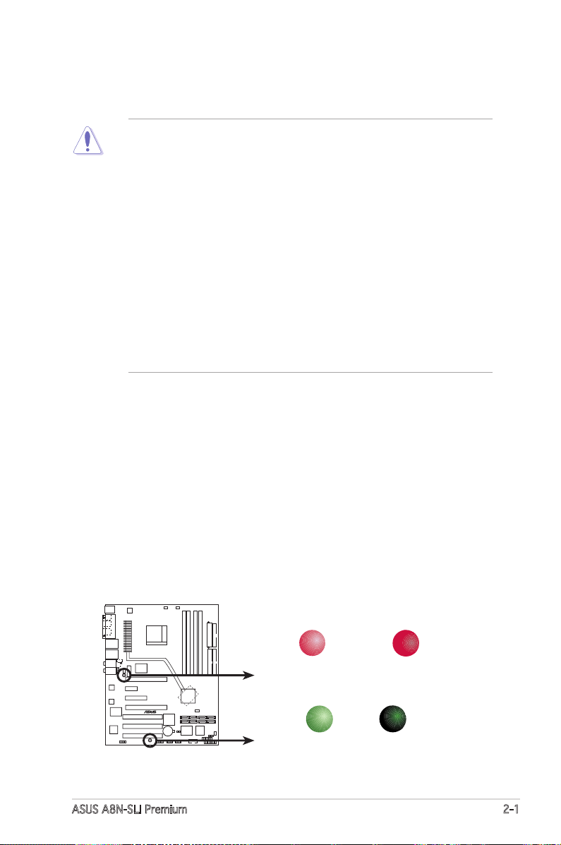
2.1 Before you proceed
A8N-SLI PREMIUM
®
A8N-SLI PREMIUM Onboard LED
SB_PWR
ON
Standby
Power
OFF
Powered
Off
SLI_WARN_LED
When use 2 Graphics
but do not plug EZ-PLUG
ON OFF
When use 2 Graphics
but do plug EZ-PLUG
Take note of the following precautions before you install motherboard
components or change any motherboard settings.
• Make sure that your power supply unit (PSU) can provide at least
the minimum power required by your system. See “8. ATX power
connectors” on page 2-26 for details.
• Unplug the power cord from the wall socket before touching any
component.
• Use a grounded wrist strap or touch a safely grounded object or
to a metal object, such as the power supply case, before handling
components to avoid damaging them due to static electricity
• Hold components by the edges to avoid touching the ICs on them.
• Whenever you uninstall any component, place it on a grounded
antistatic pad or in the bag that came with the component.
• Before you install or remove any component, ensure that the ATX
power supply is switched off or the power cord is detached from
the power supply. Failure to do so may cause severe damage to the
motherboard, peripherals, and/or components.
Onboard LED
The motherboard comes with a standby power LED that lights up to
indicate that the system is ON, in sleep mode, or in soft-off mode.
This is a reminder that you should shut down the system and unplug
the power cable before removing or plugging in any motherboard
component. The illustration below shows the location of the onboard
LED.
The red warning LED lights up when you installed two graphics card
but did not connect the ASUS EZ Plug™. The illustration below shows
the location of the onboard LEDs.
ASUS A8N-SLI Premium 2-1
Page 28
A8N-SLI PREMIUM
®
2.2 Motherboard overview
Before you install the motherboard, study the configuration of your chassis
to ensure that the motherboard fits into it.
Make sure to unplug the power cord before installing or removing the
motherboard. Failure to do so can cause you physical injury and damage
motherboard components.
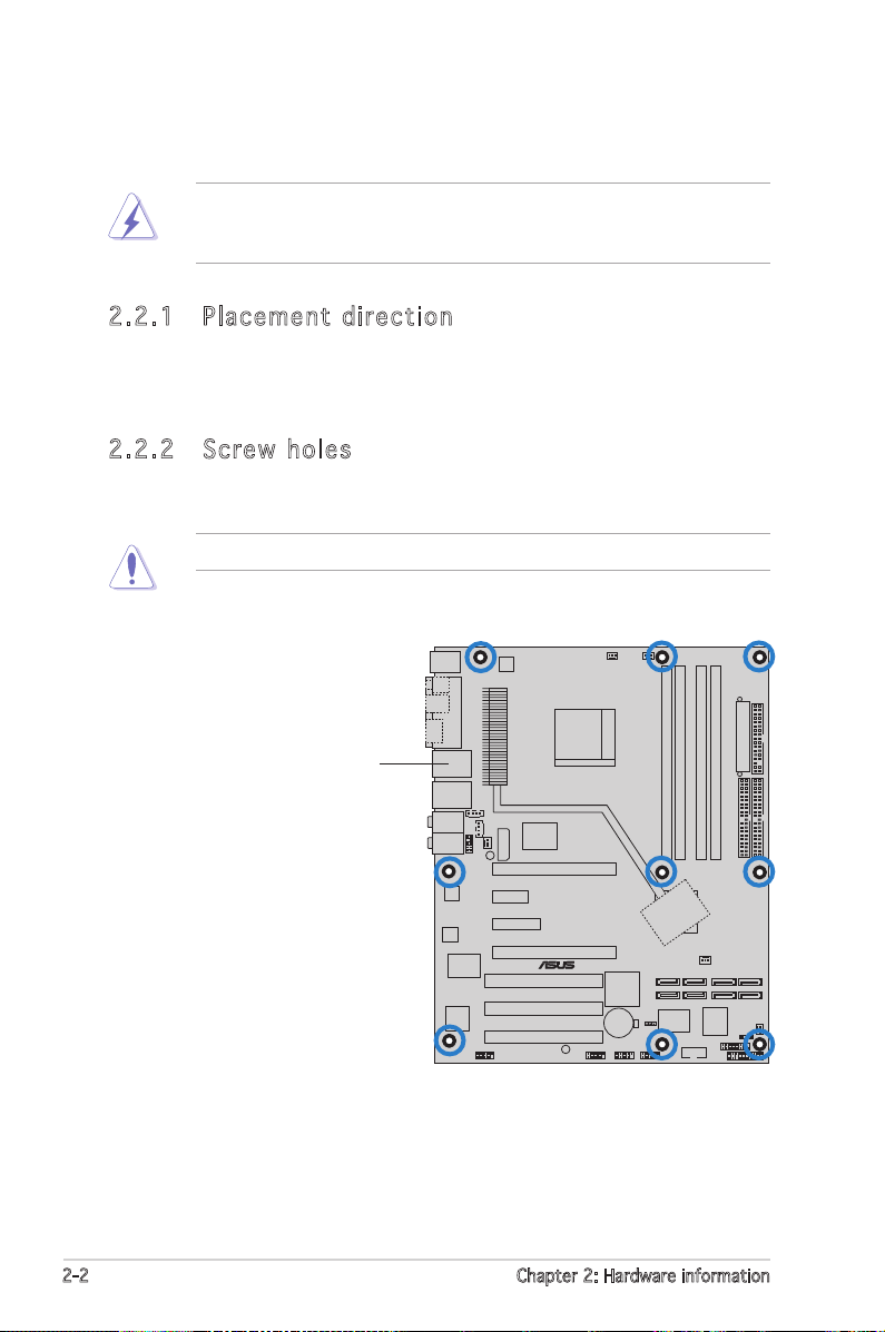
2.2 .1 Pla ce me nt di re cti on
When installing the motherboard, make sure that you place it into the
chassis in the correct orientation. The edge with external ports goes to the
rear part of the chassis as indicated in the image below.
2.2 .2 Scr ew h ole s
Place nine (9) screws into the holes indicated by circles to secure the
motherboard to the chassis.
Do not overtighten the screws! Doing so can damage the motherboard.
Place this side towards
the rear of the chassis
2-2 Chapter 2: Hardware information
Page 29
Bottom:Mic In
Center:Line Out
Top:Line In
Below:
Center/Subwoofer
Center
:
Side Speaker Ou
t
Top:Rear Speaker Out
PANEL
A8N-SLI PREMIUM
R
CR2032 3V
Lithium Cell
CMOS Power
AUX
FP_AUDIO
GAME
CHASSIS
PRI_IDE
SEC_IDE
EATXPWR
Marvell
88E8001
COM1
24.5cm (9.6in)
30.5cm (12.0in)
CPU_FAN
Socket 939
DDR DIMM_B1 (64 bit,184-pin module)
DDR DIMM_A1 (64 bit,184-pin module)
DDR DIMM_A2 (64 bit,184-pin module)
DDR DIMM_B2 (64 bit,184-pin module)
CHA2_FAN
LAN2_USB12
IE_1394_2
SATA_RAID3
PWR_FAN
FLOPPY
Super
I/O
1394
Controller
4Mb
BIOS
Silicon Image
Sil3114
PS/2KBMS
T: Mouse
B: Keyboard
PARALLEL PORT
SPDIF_O
SPDIF_O2
LAN1_USB34
CD
WARN_LED
EZ_PLUG
Speech
Controller
ACL850
PCIEX16_1
PCIEX1_1
PCIEX16_2
PCI
1
PCI
2
PCI
3
Marvell
88E1115
CLRTC
USB78 USB56 USB910
SATA3SATA4
SATA1SATA2
SATA_RAID4
SATA_RAID1SATA_RAID2
CHA1_FAN
ATX12V
1394
nVIDIA
CK804
CHIP_FAN
SB_PWR
PCIEX4_1
AI Cool-Pipe
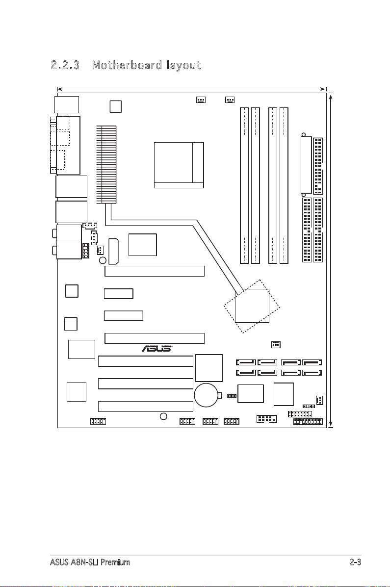
2.2 .3 Mot he rb oar d la you t
ASUS A8N-SLI Premium 2-3
Page 30
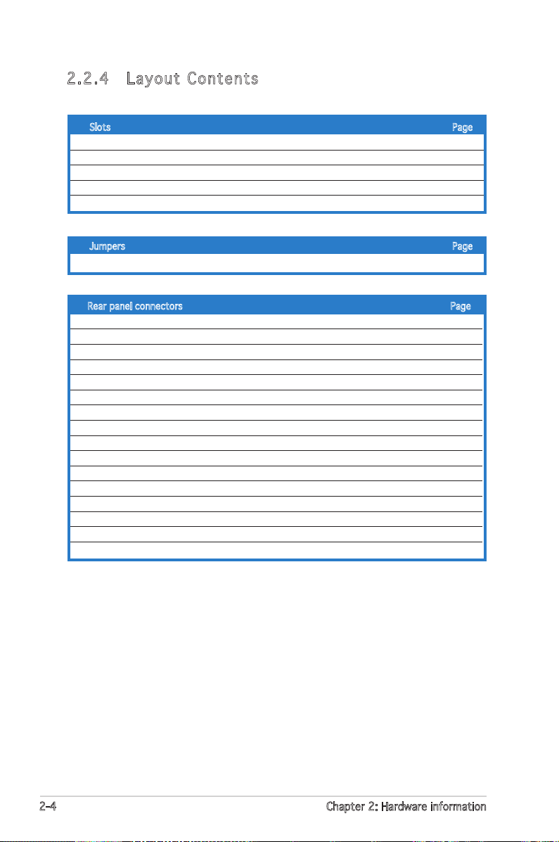
2.2 .4 Lay ou t Con te nt s
Slots Page
1. DDR DIMM slots 2-11
2. PCI slots 2-17
3. PCI Express x16 slot 2-17
4. PCI Express x1 slot 2-17
5. PCI Express x4 slot 2-17
Jumpers Page
1. Clear RTC RAM (3-pin CLRTC1) 2-18
Rear panel connectors Page
1. PS/2 mouse port (green) 2-19
2. Parallel port 2-19
3. LAN 2 (RJ-45) port 2-19
4. LAN 1 (RJ-45) port 2-19
5. Rear Speaker Out port (gray) 2-19
6. Side Speaker Out port (black) 2-19
7. Line In port (light blue) 2-19
8. Line Out port (lime) 2-19
9. Microphone port (pink) 2-20
10. Center/Subwoofer port (yellow orange) 2-20
11. USB 2.0 ports 3 and 4 2-20
12. USB 2.0 ports 1 and 2 2-20
13. IEEE 1394a port 2-20
14. Optical S/PDIF out port 2-20
15. Coaxial S/PDIF out port 2-20
16. PS/2 keyboard port (purple) 2-20
2-4 Chapter 2: Hardware information
Page 31

Internal connectors Page
1. Floppy disk drive connector (34-1 pin FLOPPY) 2-21
2. Primary IDE connector (40-1 pin PRI_IDE) 2-21
3. Secondary IDE connector (40-1 pin SEC_IDE) 2-21
4. nForce 4 Serial ATA connectors (7-pin SATA1, SATA2, SATA3, SATA4) 2-22
5. Silicon Image Serial ATA RAID connectors (7-pin SATA_RAID1, SATA_RAID2,
SATA_RAID3, SATA_RAID4) 2-23
6. CPU fan connector (3-pin CPU_FAN) 2-24
7. Power fan connector (3-pin PWR_FAN) 2-24
8. Chassis fan 1 connector (3-pin CHA1_FAN) 2-24
9. Chassis fan 2 connector (3-pin CHA2_FAN) 2-24
10. Chipset fan connector (3-pin CHIP_FAN) 2-24
11. Serial port connector (10-1 pin COM1) 2-25
12. USB headers (10-1 USB56, USB78, USB910) 2-25
13. ATX power connector (24-pin EATXPWR1) 2-26
14. ATX 12V power connector (4-pin ATX12V1) 2-26
15. ATX 12V power connector (4-pin EZ_PLUG) 2-26
16. Optical audio connector (4-pin CD) 2-27
17. Auxiliary audio connector (4-pin AUX) 2-27
18. GAME/MIDI connector (16-1 pin GAME) 2-27
19. Chassis intrusion connector (4-1 pin CHASSIS) 2-28
20. IEEE 1394a connector (10-1 pin IE1394_2) 2-28
21. Front panel audio connector (10-1 pin FP_AUDIO) 2-29
22. System panel connectors (20-1 pin PANEL) 2-29
- System Power LED (Green 3-pin PLED)
- Hard Disk activity (Red 2-pin IDE_LED)
- System warning speaker (Orange 4-pin SPEAKER)
- Power/Soft-off button(Yellow 2-pin PWRSW)
- Reset switch (Blue 2-pin RESET)
ASUS A8N-SLI Premium 2-5
Page 32

2.3 Central Processing Unit (CPU)
A8N-SLI PREMIUM
®
A8N-SLI PREMIUM CPU Socket 939
2.3 .1 Ove rv ie w
The motherboard comes with a surface mount 939-pin Zero Insertion Force
(ZIF) socket designed for the AMD Athlon™ 64FX or AMD Athlon 64™
processor.
The 128-bit-wide data paths of these processors can run applications
faster than processors with only 32-bit or 64-bit wide data paths.
Take note of the marked corner (with
gold triangle) on the CPU. This mark
should match a specific corner on the
socket to ensure correct installation.
Gold triangle
2.3 .2 Ins ta ll lin g th e C PU
To install a CPU:
1. Locate the CPU socket on the motherboard.
Before installing the CPU, make sure that the socket box is facing
towards you and the load lever is on your left.
2-6 Chapter 2: Hardware information
Page 33

2. Unlock the socket by pressing the
lever sideways, then lift it up to a
90°-100° angle.
Soc k e t Leve r
Make sure that the socket lever is lifted up to 90°-100° angle, otherwise
the CPU does not fit in completely.
3. Position the CPU above the
socket such that the CPU corner
with the gold triangle matches
the socket corner with a small
triangle.
4. Carefully insert the CPU into the
socket until it fits in place.
Gol d t riang l e
Sma l l trian g l e
The CPU fits only in one correct orientation. DO NOT force the CPU into
the socket to prevent bending the pins and damaging the CPU!
5. When the CPU is in place, push
down the socket lever to secure
the CPU. The lever clicks on the
side tab to indicate that it is
locked.
ASUS A8N-SLI Premium 2-7
Page 34

2.3 .3 Ins ta ll ing t he h e at si nk an d fa n
The AMD Athlon™ 64FX or AMD Athlon 64™ processor require a specially
designed heatsink and fan assembly to ensure optimum thermal condition
and performance.
Make sure that you use only qualified heatsink and fan assembly.
Follow these steps to install the CPU heatsink and fan.
1. Place the heatsink on top of the installed CPU, making sure that the
heatsink fits properly on the retention module base.
• The retention module base is already installed on the motherboard
upon purchase.
• You do not have to remove the retention module base when
installing the CPU or installing other motherboard components.
• If you purchased a separate CPU heatsink and fan assembly, make
sure that a Thermal Interface Material is properly applied to the CPU
heatsink or CPU before you install the heatsink and fan assembly.
CPU F a n
CPU H e atsin k
Ret e n t ion M o d u le Ba s e
Ret e n t ion b r a c ket l o c kRet e n t ion b r a c ket
Your boxed CPU heatsink and fan assembly should come with installation
instructions for the CPU, heatsink, and the retention mechanism. If the
instructions in this section do not match the CPU documentation, follow
the latter.
2-8 Chapter 2: Hardware information
Page 35

2. Attach one end of the retention bracket to the retention module base.
3. Align the other end of the retention bracket (near the retention
bracket lock) to the retention module base. A clicking sound denotes
that the retention bracket is in place.
Make sure that the fan and
heatsink assembly perfectly
fits the retention mechanism
module base, otherwise you
cannot snap the retention
bracket in place.
4. Push down the retention bracket lock on the retention mechanism to
secure the heatsink and fan to the module base.
ASUS A8N-SLI Premium 2-9
Page 36

3. When the fan and heatsink assembly is in place, connect the CPU fan
A8N-SLI PREMIUM
®
A8N-SLI PREMIUM CPU fan connector
CPU_FAN
GND
Rotation
+12V
cable to the connector on the motherboard labeled CPU_FAN.
Do not forget to connect the CPU fan connector! Hardware monitoring
errors can occur if you fail to plug this connector.
2-10 Chapter 2: Hardware information
Page 37

2.4 System memory
A8N-SLI PREMIUM
®
A8N-SLI PREMIUM 184-pin DDR DIMM sockets
DIMM_A1
DIMM_A2
DIMM_B1
DIMM_B2
2.4 .1 Ove rv ie w
The motherboard comes with four 184-pin Double Data Rate (DDR) Dual
Inline Memory Modules (DIMM) sockets.
The following figure illustrates the location of the sockets:
Channel Sockets
Channel A DIMM_A1 and DIMM_A2
Channel B DIMM_B1 and DIMM_B2
2.4 .2 Mem or y Con fi gu rat io ns
You may install 256 MB, 512 MB and 1 GB unbuffered ECC or non-ECC
DDR DIMMs into the DIMM sockets using the memory configurations in this
section.
•
For dual-channel configuration, the total size of memory module(s)
installed per channel must be the same for better performance
(DIMM_A1+DIMM_A2=DIMM_B1+DIMM_B2).
•
When using one DDR DIMM module, install into DIMM_B1 slot only.
•
When using two DDR DIMM modules, install into DIMM_A1 and
DIMM_B1 slots only.
•
Always install DIMMs with the same CAS latency. For optimum
compatibility, it is recommended that you obtain memory modules
from the same vendor. Refer to the DDR400 Qualified Vendors List
on the next page for details.
• Due to chipset resource allocation, the system may detect less than
4 GB of system memory when you installed four 1 GB DDR memory
modules.
• Due to CPU limitation, DIMM modules with 128 Mb memory chips
or double-sided x16 memory chips are not supported in this
motherboard.
ASUS A8N-SLI Premium 2-11
Page 38

Tab l e 2 D D R4 0 0 Q u al i fie d V e ndo r s L ist
Size Vendor Model Brand Side(s) Component A B C
256MB KINGSTON KVR400X64C3A/256 Hynix SS HY5DU56822BT-D43 • • •
512MB KINGSTON KVR400X64C3A/512 Hynix DS HY5DU56822BT-D43 • • •
256MB KINGSTON KVR400X72C3A/256 Mosel SS V58C2256804SAT5(ECC) • • •
512MB KINGSTON KVR400X72C3A/512 Mosel DS V58C2256804SAT5(ECC) • • •
256MB KINGSTON KVR400X64C3A/256 Infineon SS HYB25D256800BT-5B • • •
512MB KINGSTON KVR400X64C3A/512 Infineon DS HYB25D256809BT-5B • • •
256MB KINGSTON KVR400X64C3A/256 KINGSTON SS D3208DL2T-5 • • •
512MB KINGSTON KVR400X64C3A/512 KINGSTON DS D328DIB-50 • • •
512MB KINGSTON KHX3200A/512 N/A DS N/A • •
1024MB KINGSTON KVR400X64C3A/1G N/A DS HYB25D512800BE-5B • •
256MB SAMSUNG M381L3223ETM-CCC SAMSUNG SS K4H560838E-TCCC(ECC) • • •
512MB SAMSUNG M381L6423ETM-CCC SAMSUNG DS K4H560838E-TCCC(ECC) • • •
256MB SAMSUNG M368L3223ETM-CCC SAMSUNG SS K4H560838E-TCCC • •
256MB SAMSUNG M368L3223FTN-CCC SAMSUNG SS K4H560838F-TCCC • • •
512MB SAMSUNG M368L6423FTN-CCC SAMSUNG DS K4H560838F-TCCC • •
512MB SAMSUNG M368L6523BTM-CCC SAMSUNG SS K4H510838B-TCCC • • •
256MB MICRON MT8VDDT3264AG-40BCB MICRON SS MT46V32M8TG-5BC • • •
512MB MICRON MT16VDDT6464AG-40BCB MICRON DS MT46V32M8TG-5BC • •
256MB Infineon HYS64D32300HU-5-C Infineon SS HYB25D256800CE-5C • • •
512MB Infineon HYS64D64320HU-5-C Infineon DS HYB25D256800CE-5C • • •
256MB CORSAIR CMX256A-3200C2PT Winbond SS W942508BH-5 • • •
512MB CORSAIR VS512MB400 VALUE seLecT DS VS32M8-5 • • •
512MB CORSAIR CMX512-3200C2 N/A DS N/A • •
1024MB CORSAIR TWINX2048-3200C2 N/A DS N/A • •
256MB Hynix HYMD232645D8J-D43 Hynix SS HY5DU56822DT-D43 • • •
512MB Hynix HYMD264646D8J-D43 Hynix DS HY5DU56822DT-D43 • • •
256MB GEIL GE2563200B GEIL SS GL3LC32G88TG-5A • • •
512MB GEIL GE5123200B GEIL DS GL3LC32G88TG-5A • • •
256MB GEIL GD3200-256V GEIL SS GLIL DDR 32M8 • • •
512MB GEIL GD3200-512V GEIL DS GLIL DDR 32M8 • • •
256MB TwinMOS M2G9I08AIATT9F081AADT TwinMOS SS TMD7608F8E50D • • •
12MB TwinMOS M2G9J16AJATT9F081AADT TwinMOS DS TMD7608F8E50D • • •
256MB TwinMOS M2G9I08A8ATT9F081AADT TwinMOS SS TMD7608F8E50D • • •
512MB TwinMOS M2G9J16A8ATT9F081AADT TwinMOS DS TMD7608F8E50D • • •
256MB Transcend TS32MLD64V4F3 SAMSUNG SS K4H560838F-TCCC • • •
512MB Transcend TS64MLD64V4F3 SAMSUNG DS K4H560838F-TCCC • • •
1024MB Transcend TS128MLD64V4J SAMSUNG DS K4H510838B-TCCC • •
256MB Apacer 77.10636.33G Infineon SS HYB25D256800CE-5C • • •
512MB Apacer 77.10736.33G Infineon DS HYB25D256800CE-5C • • •
256MB Apacer 77.10639.60G ProMOS SS V58C2256804SCT5B • • •
512MB Apacer 77.10739.60G ProMOS DS V58C2256804SCT5B • • •
256MB A DATA MDOSS6F3G31Y0K1E0Z SAMSUNG SS K4H560838E-TCCC • • •
512MB A DATA MDOSS6F3H41Y0N1E0Z SAMSUNG DS K4H560838F-TCCC • • •
256MB A DATA MDOHY6F3G31Y0N1E0Z Hynix SS HY5DU56822CT-D43 • • •
512MB A DATA MDOHY6F3H41Y0N1E0Z Hynix DS HY5DU56822CT-D43 • •
256MB A DATA MDOAD5F3G31Y0D1E02 N/A SS ADD8608A8A-5B • • •
512MB A DATA MDOAD5F3H41Y0D1E02 N/A DS ADD8608A8A-5B • • •
DIMM support
(Continued on the next page)
2-12 Chapter 2: Hardware information
Page 39

DDR 4 00 Qua l ifi ed V end ors Lis t
Size Vendor Model Brand Side(s) Component A B C
256MB Winbond W9425GCDB-5 Winbond SS W942508CH-5 • • •
512MB Winbond W9451GCDB-5 Winbond DS W942508CH-5 • • •
256MB PSC AL5D8B53T-5B1K PSC SS A2S56D30BTP • • •
512MB PSC AL6D8B53T-5B1K PSC DS A2S56D30BTP • • •
256MB KINGMAX MPXB62D-38KT3R N/A SS KDL388P4LA-50 • • •
512MB KINGMAX MPXC22D-38KT3R N/A DS KDL388P4LA-50 • • •
256MB NANYA NT256D64S88C0G-5T N/A SS NT5DS32M8CT-5T • •
512MB NANYA NT512D64S8HC0G-5T N/A DS NT5DS32M8CT-5T • • •
256MB BRAIN POWER B6U808-256M-SAM-400 SAMSUNG SS K4H560838D-TCC4 • • •
512MB BRAIN POWER B6U808-512M-SAM-400 SAMSUNG DS K4H560838D-TCC4 • • •
256MB CENTURY DXV6S8EL5BM3T27C SAMSUNG SS K4H560838E-TCCC • • •
512MB CENTURY DXV2S8EL5BM3T27C SAMSUNG DS K4H560838E-TCCC • • •
256MB CENTURY DXV6S8EL5BM3T27C N/A SS DD2508AMTA • • •
512MB CENTURY DXV2S8EL5BM3T27C N/A DS DD2508AMTA • •
256MB elixir M2U25664DS88C3G-5T N/A SS N2DS25680CT-5T • • •
512MB elixir M2U51264DS8HC1G-5T N/A DS N2DS25680CT-5T • • •
256MB Kreton N/A VT SS VT3225804T-5 • • •
512MB Kreton N/A VT DS VT3225804T-5 • • •
256MB Veritech VT400FMV/2561103 VT SS VT56DD32M8PC-5 • • •
512MB Veritech VT400FMV/5121003 VT DS VT56DD32M8PC-5 • • •
256MB Pmi MD44256VIT3208GMHA01 MOSEL SS V58C2256804SAT5B • • •
512MB Pmi MD44512VIT3208GATA03 MOSEL DS V58C2256804SAT5B • • •
256MB ProMOS V826632K24SCTG-D0 N/A SS V58C2256804SCT5B • • •
512MB ProMOS V826664K24SCTG-D0 N/A DS V58C2256804SCT5B • • •
256MB Deutron AL5D8C53T-5B1T PSC SS A2S56D30CTP • • •
512MB Deutron AL6D8C53T-5B1T PSC DS A2S56D30CTP • • •
512MB crucial BL6464Z402.16TG Ballistix DS N/A • •
256MB Novax 96M425653CE-40TB6 CEON SS C2S56D30TP-5 • • •
512MB Novax 96M451253CE-40TB6 CEON DS C2S56D30TP-5 • • •
1024MB KINGSTON KVR400X64C3A/1G N/A DS HYB25D512800BE-5B • • •
1024MB CORSAIR TWINX2048-3200C2 N/A DS N/A • • •
1024MB Transcend TS128MLD64V4J SAMSUNG DS K4H510838B-TCCC • • •
DIMM support
Side(s): SS - Single-Sided DS - Double-Sided
DIMM Support:
A - supports one module inserted into either the blue slots, in a Single-channel
memory configuration.
B - supports on pair of modules inserted into either the blue slots or the black slots
as one pair of Dual-channel memory configuration.
C - support for 4 modules inserted into the blue and black slots as two pairs of
Dual-channel memory configuration.
Visit the ASUS website (www.asus.com) for the latest DDR 400 Qualified
Vendors List.
ASUS A8N-SLI Premium 2-13
Page 40

2.4 .3 Ins ta ll ing a D IM M
Make sure to unplug the power supply before adding or removing DIMMs
or other system components. Failure to do so may cause severe damage
to both the motherboard and the components.
1. Unlock a DIMM socket by
pressing the retaining clips
outward.
2. Align a DIMM on the socket
such that the notch on the
DIMM matches the break on the
socket.
A DDR DIMM is keyed with a notch so that it fits in only one direction.
DO NOT force a DIMM into a socket to avoid damaging the DIMM.
3. Firmly insert the DIMM into the
socket until the retaining clips
snap back in place and the DIMM
is properly seated.
2
DDR D I MM no t c h
1
1
Unl o c k ed re t a i ning c l i p
Loc k e d Reta i n i ng Cl i p
2.4 .4 Rem ov in g a D IM M
Follow these steps to remove a DIMM.
1. Simultaneously press the
retaining clips outward to unlock
the DIMM.
1
Support the DIMM lightly with your fingers when pressing the retaining
clips. The DIMM might get damaged when it flips out with extra force.
DDR D I MM no t c h
2. Remove the DIMM from the socket.
2-14 Chapter 2: Hardware information
2
1
Page 41

2.5 Expansion slots
In the future, you may need to install expansion cards. The following
sub-sections describe the slots and the expansion cards that they support.
Make sure to unplug the power cord before adding or removing
expansion cards. Failure to do so may cause you physical injury and
damage motherboard components.
2.5 .1 Ins ta ll ing a n ex p an si on ca rd
To install an expansion card:
1. Before installing the expansion card, read the documentation that
came with it and make the necessary hardware settings for the card.
2. Remove the system unit cover (if your motherboard is already
installed in a chassis).
3. Remove the bracket opposite the slot that you intend to use. Keep
the screw for later use.
4. Align the card connector with the slot and press firmly until the card is
completely seated on the slot.
5. Secure the card to the chassis with the screw you removed earlier.
6. Replace the system cover.
2.5 .2 Con fi gu rin g an e x pa ns io n c ar d
After installing the expansion card, configure the it by adjusting the
software settings.
1. Turn on the system and change the necessary BIOS settings, if any.
See Chapter 4 for information on BIOS setup.
2. Assign an IRQ to the card. Refer to the tables on the next page.
3. Install the software drivers for the expansion card.
ASUS A8N-SLI Premium 2-15
Page 42

2.5 .3 Int er ru pt as si gnm en ts
Sta n da r d i n te r rup t a s sig n me n ts
IRQ Priority Standard Function
0 1 System Timer
1 2 Keyboard Controller
2 – Re-direct to IRQ#9
4 12 Communications Port (COM1)*
5 13 IRQ holder for PCI steering*
6 14 Floppy Disk Controller
7 15 Printer Port (LPT1)*
8 3 System CMOS/Real Time Clock
9 4 IRQ holder for PCI steering*
10 5 IRQ holder for PCI steering*
11 6 IRQ holder for PCI steering*
12 7 PS/2 Compatible Mouse Port*
13 8 Numeric Data Processor
14 9 Primary IDE Channel
15 10 Secondary IDE Channel
* These IRQs are usually available for ISA or PCI devices.
IRQ as s ign m en t s f o r t his mo t her b oa r d
A B C D E F G H
PCI slot 1 shared — — — — — — —
PCI slot 2 — shared — — — — — —
PCI slot 3 — — shared — — — — —
Onboard USB 1.0 controller shared — — — — — — —
Onboard USB 2.0 controller shared — — — — — — —
Onboard LAN1 shared — — — — — — —
Onboard LAN2 — shared — — — — — —
Onboard PCI SATA RAID (SI) — — — shared — — — —
Onboard 1394a shared — — — — — — —
When using PCI cards on shared slots, ensure that the drivers support
“Share IRQ” or that the cards do not need IRQ assignments. Otherwise,
conflicts will arise between the two PCI groups, making the system
unstable and the card inoperable.
2.5 .4 PCI s lo ts
The PCI slots support cards such as
a LAN card, SCSI card, USB card, and
other cards that comply with PCI
specifications. The figure shows a
LAN card installed on a PCI slot.
2-16 Chapter 2: Hardware information
Page 43

2.5 .5 Two P CI Ex pr es s x 16 s lot s
This motherboard supports one PCI
Express x16 graphics card or two
SLI-ready PCI Express x16 graphic
cards that comply with the PCI
Express specifications. The figure
shows a graphics card installed on the
PCI Express x16 slot.
See Chapter 6 for details on the SLI
technology feature.
In Single Video Card mode, only the PCI Express blue slot can be used for
PCI Express x16 graphics cards.
2.5 .6 PCI E xp res s x1 sl ot
This motherboard supports PCI
Express x1 network cards, SCSI cards
and other cards that comply with the
PCI Express specifications. The figure
shows a network card installed on the
PCI Express x1 slot.
2.5 .7 PCI E xp res s x4 sl ot
This motherboard provides a PCI
Express x4 slot that can support PCI
Express x1, x4, x8, or x16 cards. This
ASUS proprietary slot allows you to
use additional PCI Express cards
(e.g. graphics card) for twice the
speed of a PCI Express x1 slot.
The Universal PCIe slot
supports a total bandwidth of
1GB/s.
ASUS A8N-SLI Premium 2-17
Page 44

2.6 Jumpers
A8N-SLI PREMIUM
®
A8N-SLI PREMIUM Clear RTC RAM
CLRTC
Normal Clear CMOS
(Default)
1 2
2 3
1. C l e ar R T C RAM ( C L RTC)
This jumper allows you to clear the Real Time Clock (RTC) RAM in
CMOS. You can clear the CMOS memory of date, time, and system
setup parameters by erasing the CMOS RTC RAM data. The onboard
button cell battery powers the RAM data in CMOS, which include
system setup information such as system passwords.
To erase the RTC RAM:
1. Turn OFF the computer and unplug the power cord.
2. Remove the onboard battery.
3. Move the jumper cap from pins 1-2 (default) to pins 2-3. Keep the
cap on pins 2-3 for about 5~10 seconds, then move the cap back to
pins 1-2.
4. Re-install the battery.
5. Plug the power cord and turn ON the computer.
6. Hold down the <Del> key during the boot process and enter BIOS
setup to re-enter data.
Except when clearing the RTC RAM, never remove the cap on CLRTC
jumper default position. Removing the cap will cause system boot failure!
You do not need to clear the RTC when the system hangs due to
overclocking. For system failure due to overclocking, use the C.P.R. (CPU
Parameter Recall) feature. Shut down and reboot the system so the BIOS
can automatically reset parameter settings to default values.
2-18 Chapter 2: Hardware information
Page 45

2.7 Connectors
SPEED
LED
ACT/LINK
LED
LAN port
11
4 5106
7
8
9
1
16
2
15 14 12
3
13
2.7 .1 Rea r pa nel c on nec to rs
1. PS/2 mouse port (green). This port is for a PS/2 mouse.
2. Parallel port. This 25-pin port connects a parallel printer, a scanner, or
other devices.
3. LAN 2 (RJ-45) port. Supported by the Marvell® 88E81001 Gigabit LAN
controller, this port allows Gigabit connection to a Local Area Network
(LAN) through a network hub.
4. LAN 1 (RJ-45) port. Supported by the NVIDIA® nForce™ 4 Gigabit MAC
with external Marvell® PHY, this port allows Gigabit connection to a
Local Area Network (LAN) through a network hub. Refer to the table
below for the LAN port LED indications.
LAN po r t L E D i ndi c at i ons
ACT/LINK LED SPEED LED
Status Description Status Description
OFF No link OFF 10 Mbps connection
GREEN Linked ORANGE 100 Mbps connection
BLINKING Data activity GREEN 1 Gbps connection
5. Rear Speaker Out port (gray). This port connects the rear speakers on
a 4-channel, 6-channel, or 8-channel audio configuration.
6. Side Speaker Out port (black). This port connects the side speakers in
an 8-channel audio configuration.
7. Line In port (light blue). This port connects the tape, CD, DVD player,
or other audio sources.
8. Line Out port (lime). This port connects a headphone or a speaker. In
4-channel, 6-channel, and 8-channel configuration, the function of this
port becomes Front Speaker Out.
ASUS A8N-SLI Premium 2-19
Page 46

9. Microphone port (pink). This port connects a microphone.
10. Center/Subwoofer port (yellow orange). This port connects the
center/subwoofer speakers.
Refer to the audio configuration table below for the function of the audio
ports in 2, 4, 6, or 8-channel configuration.
Aud i o 2 , 4 , 6, or 8-c han n el con f igu rat i on
Port Headset 4-channel 6-channel 8-channel
2-channel
Light Blue Line In Line In Line In Line In
Lime Line Out Front Speaker Out Front Speaker Out Front Speaker Out
Pink Mic In Mic In Mic In Mic In
Gray • Rear Speaker Out Rear Speaker Out Rear Speaker Out
Black • • • Side Speaker Out
Yellow Orange • • Center/Subwoofer Center/Subwoofer
11. USB 2.0 ports 3 and 4. These two 4-pin Universal Serial Bus (USB)
ports are available for connecting USB 2.0 devices.
12. USB 2.0 ports 1 and 2. These two 4-pin Universal Serial Bus (USB)
ports are available for connecting USB 2.0 devices.
13. IEEE 1394a port. This 6-pin IEEE 1394 port provides high-speed
connectivity for audio/video devices, storage peripherals, PCs, or
portable devices.
14. Optical S/PDIF Out port. This port connects an external audio output
device via an optical S/PDIF cable.
15. Coaxial S/PDIF Out port. This port connects an external audio output
device via a coaxial S/PDIF cable.
16. PS/2 keyboard port (purple). This port is for a PS/2 keyboard.
2-20 Chapter 2: Hardware information
Page 47

2.7 .2 Int er na l c on ne cto rs
A8N-SLI PREMIUM
®
A8N-SLI PREMIUM Floppy disk drive connector
NOTE: Orient the red markings on
the floppy ribbon cable to PIN 1.
PIN 1
FLOPPY
A8N-SLI PREMIUM
®
A8N-SLI PREMIUM IDE connectors
NOTE: Orient the red markings
(usually zigzag) on the IDE
ribbon cable to PIN 1.
PRI_IDE
PIN 1
SEC_IDE
1. F l o ppy d i s k dr i v e con n e c tor ( 3 4 -1 p i n FLOP P Y )
This connector is for the provided floppy disk drive (FDD) signal cable.
Insert one end of the cable to this connector, then connect the other
end to the signal connector at the back of the floppy disk drive.
The Pin 5 on the connector is removed to prevent incorrect cable
connection when using an FDD cable with a covered Pin 5.
2. I D E con n e c tors ( 4 0-1 p i n PRI _ I D E, S E C _ IDE)
These connectors are for Ultra DMA 133/100/66 signal cables.
The Ultra DMA 133/100/66 signal cable has three connectors: a
blue connector for the primary IDE connector on the motherboard,
a black connector for an Ultra DMA 133/100/66 IDE slave device
(optical drive/hard disk drive), and a gray connector for an Ultra
DMA 133/100/66 IDE master device (hard disk drive). If you install
two hard disk drives, you must configure the second drive as a slave
device by setting its jumper accordingly. Refer to the hard disk
documentation for the jumper settings.
• The Pin 20 on the IDE connector is removed to match the covered hole
on the Ultra DMA cable connector. This prevents incorrect insertion
when you connect the IDE cable.
• Use the 80-conductor IDE cable for UltraDMA133/100/66 IDE devices.
ASUS A8N-SLI Premium 2-21
Page 48

3. S e r ial A T A con n e c tors
A8N-SLI PREMIUM
®
A8N-SLI PREMIUM SATA connectors
SATA3SATA4
GND
RSATA_TXP4
RSATA
_TXN4
GND
RSATA
_RXP4
RSATA
_RXN4
GND
GND
RSATA_TXP3
RSATA
_TXN3
GND
RSATA
_RXP3
RSATA
_RXN3
GND
GND
RSATA_TXP2
RSATA_TXN2
GND
RSATA
_RXP2
RSATA
_RXN2
GND
GND
RSATA_TXP1
RSATA_TXN1
GND
RSATA
_RXP1
RSATA
_RXN1
GND
SATA1SATA2
(7-p i n SATA 1 , SATA 2 , SATA 3 , S ATA 4 )
Supported by the NVIDIA® nForce4™ chipset, these connectors are for
the Serial ATA signal cables for Serial ATA hard disk drives that allows
up to 3Gb/s of data transfer rate.
These connectors are set to SATA by default. In SATA mode, you can
connect Serial ATA boot or data hard disk drives to these connectors.
If you intent to create a Serial ATA RAID set using these connectors,
enable the RAID function of each port from the NVRAID Configuration
sub-menu item in the BIOS. See section “4.4.3 Onboard Devices
Configuration” on pages 4-24 and 4-26 for details.
Important notes on Serial ATA
•
The actual data transfer rate depends on the speed of Serial ATA
hard disks installed.
• See Appendix for instructions on how to install the Serial ATA
extension module.
2-22 Chapter 2: Hardware information
Page 49

4. S e r ial A T A RAI D c onne c t o rs ( 7 - p in S A T A _RAI D 1 , SAT A _
A8N-SLI PREMIUM
®
A8N-SLI PREMIUM SATA RAID connectors
SATA_RAID2
GND
RSATA_TXP2
RSATA_TXN2
GND
RSATA
_RXP2
RSATA
_RXN2
GND
SATA_RAID4
GND
RSATA_TXP4
RSATA_TXN4
GND
RSATA
_RXP4
RSATA
_RXN4
GND
SATA_RAID1
GND
RSATA_TXP1
RSATA_TXN1
GND
RSATA_RXP1
RSATA
_RXN1
GND
SATA_RAID3
GND
RSATA_TXP3
RSATA_TXN3
GND
RSATA_RXP3
RSATA
_RXN3
GND
RAID 2 , SATA _ R A ID3, S A TA_R A I D 4 )
Supported by the Silicon Image® Sil3114 RAID controller, these
connectors are for Serial ATA signal cables. These connectors support
up to four Serial ATA hard disk drives that can be configured as a
disk array through the onboard Silicon Image Sil3114 SATA RAID
controller. Refer to Chapter 5 for details on how to set up Serial ATA
RAID configurations.
By default, the RAID function of these connectors are enabled. Disable
the Silicon SATA controller item in the BIOS, if you are not configuring
a set with these connectors. See section “4.4.3 Onboard Devices
Configuration” on page 4-24 for details.
• Before creating a RAID configuration, make sure that you have
connected the Serial ATA cables to these connectors and have
installed the Serial ATA hard disks drives; otherwise, you cannot
enter the Silicon Image RAID utility and Serial ATA BIOS setup during
POST.
• See Appendix for instructions on how to install the Serial ATA
extension module.
ASUS A8N-SLI Premium 2-23
Page 50

5. C P U , Ch a s s is, C h i pset a n d Po w e r fan c o nnec t o r s
A8N-SLI PREMIUM
®
A8N-SLI PREMIUM Fan connectors
CPU_FAN
CHA1_FAN
PWR_FAN
CHA2_FAN
GND
Rotation
+12V
GND
Rotation
+12V
GND
Rotation
+12V
GND
Rotation
+12V
CPU_FAN
CHA1_FAN
PWR_FAN
CHA2_FAN
CHIP_FAN
GND
Rotation
+12V
CHIP_FAN
(3-p i n CPU_ F A N , 3- p i n CHA 2 _ F A N, 3 - p i n CH I P _ FAN,
3-p i n PWR_ F A N , 3- p i n CHA 1 _ F A N)
The fan connectors support cooling fans of 350mA~2000mA (24
W max.) or a total of 1A~3.48A (41.76 W max.) at +12V. Connect
the fan cables to the fan connectors on the motherboard, making
sure that the black wire of each cable matches the ground pin of the
connector.
• Do not forget to connect the fan cables to the fan connectors. Lack
of sufficient air flow inside the system may damage the motherboard
components. These are not jumpers! DO NOT place jumper caps on
the fan connectors!
• The ASUS Q-Fan function is supported using the CPU Fan (CPU_FAN)
and Chassis Fan 1 (CHA1_FAN) connectors only.
• The chipset fan is synchronized with the CPU fan.
2-24 Chapter 2: Hardware information
Page 51

6. S e r ial p o r t co n n e ctor ( 1 0-1 p i n COM 1 )
A8N-SLI PREMIUM
®
A8N-SLI PREMIUM COM port connector
PIN 1
COM1
A8N-SLI PREMIUM
®
A8N-SLI PREMIUM
USB 2.0 connectors
USB56
USB+5V
USB_P6-
USB_P6+
GND
NC
USB+5V
USB_P5-
USB_P5+
GND
1
USB78
USB+5V
USB_P8-
USB_P8+
GND
NC
USB+5V
USB_P7-
USB_P7+
GND
1
USB910
USB+5V
USB_P10-
USB_P10 +
GND
NC
USB+5V
USB_P9-
USB_P9+
GND
1
This connector is for a serial (COM) port. Connect the serial port
module cable to this connector, then install the module to a slot
opening at the back of the system chassis.
7. U S B con n e c tors ( 1 0-1 p i n USB 5 6 , USB7 8 , USB9 1 0 )
These connectors are for USB 2.0 ports. Connect the USB/GAME
module cable to any of these connectors, then install the module to a
slot opening at the back of the system chassis. These USB connectors
comply with USB 2.0 specification that supports up to 480 Mbps
connection speed.
Never connect a 1394 cable to the USB connectors. Doing so will
damage the motherboard!
ASUS A8N-SLI Premium 2-25
Page 52

8. A T X pow e r conn e c t ors ( 2 4 -pin E A TXPW R 1 ,
A8N-SLI PREMIUM
®
A8N-SLI PREMIUM ATX power connectors
EATXPWRATX12V
+12V DC GND
+12V DC GND
+3 Volts
+3 Volts
Ground
+5 Volts
+5 Volts
Ground
Ground
Power OK
+5V Standby
+12 Volts
-5 Volts
+5 Volts
+3 Volts
-12 Volts
Ground
Ground
Ground
PSON#
Ground
+5 Volts
+12 Volts
+3 Volts
+5 Volts
Ground
EZ_PLUG
+5V
EZ_DET
GND
+12V
4-pi n A TX12 V 1 , 4-pi n E Z_PL U G )
These connectors are for an ATX power supply plugs. The power
supply plugs are designed to fit these connectors in only one
orientation. Find the proper orientation and push down firmly until the
connectors completely fit.
•
Do not forget to connect the 4-pin ATX +12 V power plug;
otherwise, the system will not boot.
•
When using two graphics cards, do not forget to connect the 4-pin
ATX +12 V power plug to the EZ Plug™; otherwise, the system will
be unstable. See page 6-5 for details.
• Use of a PSU with a higher power output is recommended when
configuring a system with more power-consuming devices. The
system may become unstable or may not boot up if the power is
inadequate.
• Make sure that your power supply unit (PSU) can provide at least
the minimum power required by your system. See the table below
for details.
Pow e r s upp l y r equ i re m ent s
Loading
Components/Peripherals Heavy Normal Light
AMD® K8 939-pin CPU type Athlon 64 FX-55 Athlon 64 3800+ Athlon 64 3400+
PCIe™ x16 graphics cards 6800 Ultra x2 6800GT x2 6600GT x2
DDR DIMMs 4 2 2
HDD 4 2 2
Optical drive (DVD/CD-RW) 2 2 1
PCIe™ x 1 card 1 0 0
PCI cards 3 2 1
IEEE 1394 devices 1 0 0
USB devices 6 4 3
Required +12V current > 25A > 20A > 17A
Required wattage >= 500W >= 400W >= 350W
2-26 Chapter 2: Hardware information
Page 53

9. I n t erna l a udio c o nnec t o r s (4 - p i n CD , A UX)
A8N-SLI PREMIUM
®
A8N-SLI PREMIUM Internal audio connectors
AUX
(white)
CD
(black)
Right Audio Channel
Left Audio Channel
Ground
Ground
Right Audio Channel
Left Audio Channel
Ground
Ground
A8N-SLI PREMIUM
®
A8N-SLI PREMIUM Game connector
GAME
+5V +5V
J2B1
J2CX
MIDI_OUT
J2CY
J2B2
MIDI_IN
J1B1
J1CX
GND
GND
J1CY
J1B2
+5V
These connectors allow you to receive stereo audio input from sound
sources such as a CD-ROM, TV-tuner, or MPEG card.
The function of these connectors are disabled under 8-channel mode.
10. G A M E/MI D I port c o nnec t o r (16 - 1 pin G A M E)
This connector is for a GAME/MIDI port. Connect the USB/GAME
module cable to this connector, then install the module to a slot
opening at the back of the system chassis. The GAME/MIDI port
connects a joystick or game pad for playing games, and MIDI devices
for playing or editing audio files.
ASUS A8N-SLI Premium 2-27
Page 54

11. C h a ssis i n trus i o n con n e c tor ( 4 - 1 pi n C HASS I S )
A8N-SLI PREMIUM
®
A8N-SLI PREMIUM Chassis intrusion connector
CHASSIS
+5VSB_MB
Chassis Signal
GND
(Default)
A8N-SLI PREMIUM
®
A8N-SLI PREMIUM IEEE 1394 connector
IE_1394_2
1
GND
+12V
TPB1-
GND
TPA1-
+12V
TPB1+
GND
TPA1+
This connector is for a chassis-mounted intrusion detection sensor
or switch. Connect one end of the chassis intrusion sensor or switch
cable to this connector. The chassis intrusion sensor or switch sends
a high-level signal to this connector when a chassis component
is removed or replaced. The signal is then generated as a chassis
intrusion event.
By default, the pins labeled “Chassis Signal” and “Ground” are shorted
with a jumper cap. Remove the jumper caps only when you intend to
use the chassis intrusion detection feature.
12. I E E E 13 9 4 conn e c t or ( 1 0 - 1 pin I E 1394 _ 2 )
This connector is for the IEEE 1394a module. Connect the IEEE 1394
module cable to this connector, then install the module to a slot
opening at the back of the system chassis.
Never connect a USB cable to the IEEE 1394 connectors. Doing so will
damage the motherboard!
2-28 Chapter 2: Hardware information
Page 55

13. F r o nt p a n e l au d i o con n e c tor ( 1 0 -1 p i n FP_A U D I O )
A8N-SLI PREMIUM
®
A8N-SLI PREMIUM Front panel audio connector
FP_AUDIO
BLINE_OUT_L
MIC2
Line out_R
Line out_L
BLINE_OUT_R
NC
MICPWR+5VA
AGND
A8N-SLI PREMIUM
®
A8N-SLI PREMIUM System panel connector
* Requires an ATX power supply.
PANEL
PLED-
PWR
+5V
Speaker
Ground
RESET
Ground
Reset
Ground
Ground
PWRSW
PLED+
IDE_LED-
IDE_LED+
IDE_LED
PLED
SPEAKER
This connector is for a chassis-mounted front panel audio I/O module
that supports legacy AC ʻ97 audio standard. Connect one end of the
front panel audio I/O module cable to this connector.
14. S y s tem p a n el c o n n ecto r ( 20-p i n PANE L )
This connector supports several chassis-mounted functions.
The sytem panel connector is color-coded for easy connection. Refer to
the connector description below for details.
•
System power LED (Green 3-pin PLED)
This 3-pin connector is for the system power LED. Connect the
chassis power LED cable to this connector. The system power LED
lights up when you turn on the system power, and blinks when the
system is in sleep mode.
•
Hard disk drive activity (Red 2-pin IDE_LED)
This 2-pin connector is for the HDD Activity LED. Connect the HDD
Activity LED cable to this connector. The IDE LED lights up or flashes
when data is read from or written to the HDD.
ASUS A8N-SLI Premium 2-29
Page 56

•
System warning speaker (Orange 4-pin SPEAKER)
This 4-pin connector is for the chassis-mounted system warning
speaker. The speaker allows you to hear system beeps and warnings.
•
Power/Soft-off button (Yellow 2-pin PWRSW)
This connector is for the system power button. Pressing the power
button turns the system ON or puts the system in SLEEP or SOFT-OFF
mode depending on the BIOS settings. Pressing the power switch for
more than four seconds while the system is ON turns the system OFF.
•
Reset button (Blue 2-pin RESET)
This 2-pin connector is for the chassis-mounted reset button for
system reboot without turning off the system power.
2-30 Chapter 2: Hardware information
Page 57

This chapter describes the power up
sequence, the vocal POST messages,
and ways of shutting down the
system.
Powering up
3
Page 58

Chapter summary
3.1 Starting up for the first time ................................................ 3-1
3.2 Powering off the computer ................................................... 3-2
3.3 ASUS POST Reporter™ .......................................................... 3-3
ASUS A8N-SLI Premium
Page 59

3.1 Starting up for the first time
1. After making all the connections, replace the system case cover.
2. Be sure that all switches are off.
3. Connect the power cord to the power connector at the back of the
system chassis.
4. Connect the power cord to a power outlet that is equipped with a
surge protector.
5. Turn on the devices in the following order:
a. Monitor
b. External SCSI devices (starting with the last device on the chain)
c. System power
6. After applying power, the system power LED on the system front
panel case lights up. For systems with ATX power supplies, the system
LED lights up when you press the ATX power button. If your monitor
complies with “green” standards or if it has a “power standby”
feature, the monitor LED may light up or switch between orange and
green after the system LED turns on.
The system then runs the power-on self tests or POST. While the
tests are running, the BIOS beeps (see BIOS beep codes table below)
or additional messages appear on the screen. If you do not see
anything within 30 seconds from the time you turned on the power,
the system may have failed a power-on test. Check the jumper
settings and connections or call your retailer for assistance.
7. At power on, hold down the <Delete> key to enter the BIOS Setup.
Follow the instructions in Chapter 4.
ASUS A8N-SLI Premium 3-1
Page 60

3.2 Powering off the computer
3.2 .1 Usi ng t he OS s hut d ow n f un ct ion
If you are using Windows® 2000:
1. Click the Start button then click Shut Down...
2. Make sure that the Shut Down option button is selected, then click
the OK button to shut down the computer.
3. The power supply should turn off after Windows® shuts down.
If you are using Windows® XP:
1. Click the Start button then select Turn Off Computer.
2. Click the Turn Off button to shut down the computer.
3. The power supply should turn off after Windows® shuts down.
3.2 .2 Usi ng t he du al fu nc ti on po we r s wi tc h
While the system is ON, pressing the power switch for less than four
seconds puts the system to sleep mode or to soft-off mode, depending
on the BIOS setting. Pressing the power switch for more than four seconds
lets the system enter the soft-off mode regardless of the BIOS setting.
Refer to section “4.5 Power Menu” in Chapter 4 for details.
3-2 Chapter 3: Powering up
Page 61

3.3 ASUS POST Reporter™
This motherboard includes the Winbond speech controller to support a
special feature called the ASUS POST Reporter™. This feature lets you hear
vocal messages during POST that alerts you of system events and boot
status. In case of a boot failure, you will hear the specific cause of the
problem.
These POST messages are customizable using the Winbond Voice Editor
software that came with your package. You can record your own messages
to replace the default messages.
3.3 .1 Voc al P OST m es sag es
Following is a list of the default POST messages and the corresponding
actions you can take:
POST Message Action
No CPU installed
System failed CPU test
System failed memory test
System failed VGA test
System failed due to CPU
No keyboard detected
No IDE hard disk detected • Make sure you have connected an
•
Install a supported processor to the
CPU socket. See section “2.3 Central
Processing Unit (CPU)” for details.
•
Check the CPU if properly installed.
•
Call ASUS technical support for
assistance. See the ASUS contact
information on the inside front cover
of this user guide.
•
Install supported DDR DIMMs into the
memory sockets.
•
Check if the DIMMs on the DIMM
sockets are properly installed.
•
Make sure that your DIMMs are not
defective.
•
Refer to section “2.4 System memory”
for instructions on installing a DIMM.
•
Install a PCI graphics card into one of
the PCI slots, or a PCI Express AGP
card into the PCI Express x16 slot.
•
Make sure that your graphics card is
not defective.
•
Check your CPU overclocking settings
in the BIOS setup and restore the
default CPU parameters.
•
Check if your keyboard is properly
connected to the purple PS/2
connector on the rear panel.
• See section “2.7.1 Rear panel
connectors” for the location of the
connector.
IDE hard disk drive to one of the IDE
connectors on the motherboard.
ASUS A8N-SLI Premium 3-3
Page 62

POST Message Action
CPU temperature too high
CPU fan failed
CPU voltage out of range
Computer now booting from operating • No action required
system
•
Check if the CPU fan is working
properly.
•
Check the CPU fan and make sure it
turns on after you apply power to the
system.
•
Make sure that your CPU fan supports
the fan speed detection function.
•
Check your power supply and make
sure it is not defective.
•
Call ASUS technical support for
assistance. See the “ASUS contact
information” on the inside front cover
of this user guide.
You can enable or disable the ASUS POST Reporter™ in the Speech
Configuration option in the BIOS setup. See section 4.4.8 for details.
3-4 Chapter 3: Powering up
Page 63

3.3 .2 Win bo nd Vo ic e Edi to r
The Winbond Voice Editor software allows you to customize the vocal POST
messages. You can install this application from the support CD.
To avoid conflicts, do not run the Winbond Voice Editor while running the
ASUS PC Probe application.
Lau n ch i ng t he Voi c e E dit o r
You can launch the program from the Windows® desktop by clicking Start >
All Programs > Winbond Voice Editor > Voice Editor.
The Winbond Voice Editor screen appears.
Def a u l t Mes s a g esPOS T E vents
Pla y in g th e d e fau l t w ave fi l es
To play the default wave files, simply click on a POST event on the left side
of the screen, then click the Play button.
The default language setting is English.
ASUS A8N-SLI Premium 3-5
Page 64

Cha n gi n g t h e d efa u lt lan g ua g e
To change the default language:
1. Click the Load button from
the Voice Editor main window.
A window with the available
languages appears.
2. Select your desired language,
then click Open.
The event messages for the
language you selected appear
on the Voice Editor main
window.
Not all events on some languages have a corresponding message due to
file size constraints.
3. Click the Write button from the Voice Editor main window to update
the EEPROM.
4. Click Yes to confirm.
The next time you boot your computer, the ASUS Post Reporter announces
the messages in the selected language.
3-6 Chapter 3: Powering up
Page 65

Cus t om i zin g y o ur P OS T me s sa g es
The Voice Editor application allows you to record your own POST messages
if your language is not supported or if you wish to to replace the
pre-installed wave files.
To customize your POST messages.
1. Launch the Voice Editor application and note the list of POST events
on the leftmost column of the screen.
2. Prepare your message for each event.
3. Use a recording software (e.g. Windows® Recorder) to record your
messages, then save the messages as wave files (.WAV).
• The total compressed size for all the wave files must not exceed
1Mbit, so keep your messages as short as possible.
• To keep file sizes small, save your files at a low quality. For example,
use 8-bit, mono quality at 22Khz sampling rate.
• Create a separate folder for your wave files so you can locate them
easily.
4. From the Voice Editor screen,
click the Add button to display
the Add Wave File window.
5. Copy the wave files that you
recorded to the database, then
close the window when done.
ASUS A8N-SLI Premium 3-7
Page 66

6. Select a POST event on the
Voice Editor main window, then
click the Edit button. The Event
Sound Editor window appears.
7. Locate and select your wave file
for the event, then click on the
arrow opposite Voice1. The file
you select appears on the space
next to it.
8. Click OK to return to the Voice
Editor main window.
9. Do steps 6 to 8 for the other
events.
10. When done, click Save. A
window appears prompting you
to save your configuration.
11. Type a file name with an .flh
extension, then click Save.
12. Click the Write button to
compress the file and copy into
the EEPROM.
13. Click Yes on the confirmation
window that appears.
If you receive an error message telling you that the files exceed the total
allowable size, do any or all of the following:
•
Shorten your messages.
•
Save the wave files at a lower quality
•
Do not include seldom-used events like FDD Detection, IDE HDD
Detection, etc.
3-8 Chapter 3: Powering up
Page 67

This chapter tells how to change
the system settings through the BIOS
Setup menus. Detailed descriptions
of the BIOS parameters are also
provided.
BIOS setup
4
Page 68

Chapter summary
4.1 Managing and updating your BIOS ........................................ 4-1
4.2 BIOS setup program ............................................................ 4-11
4.3 Main menu ........................................................................... 4-15
4.4 Advanced menu .................................................................. 4-20
4.5 Power menu ........................................................................ 4-35
4.6 Boot menu .......................................................................... 4-40
4.7 Exit menu ............................................................................ 4-46
ASUS A8N SLI Premium
Page 69

4.1 Managing and updating your BIOS
The following utilities allow you to manage and update the motherboard
Basic Input/Output System (BIOS) setup.
1. Award BIOS Flash Utility (Updates the BIOS in DOS mode using a
bootable floppy disk.)
2. ASUS CrashFree BIOS 2 (Updates the BIOS using a bootable floppy
disk or the motherboard support CD when the BIOS file fails or gets
corrupted.)
3. ASUS EZ Flash (Updates the BIOS in DOS using a floppy disk or the
motherboard support CD.)
4. ASUS Update (Updates the BIOS in Windows® environment.)
Refer to the corresponding sections for details on these utilities.
Save a copy of the original motherboard BIOS file to a bootable floppy
disk in case you need to restore the BIOS in the future. Copy the original
motherboard BIOS using the ASUS Update or AwardBIOS Flash utilities.
4.1 .1 Cre at in g a b oo tab le f lop py d isk
1. Do either one of the following to create a bootable floppy disk.
DOS environment
a. Insert a 1.44MB floppy disk into the drive.
b. At the DOS prompt, type format A:/S then press <Enter>.
Windows® XP environment
a. Insert a 1.44 MB floppy disk to the floppy disk drive.
b. Click Start from the Windows® desktop, then select My Computer.
c. Select the 3 1/2 Floppy Drive icon.
d. Click File from the menu, then select Format. A Format 3 1/2
Floppy Disk window appears.
e. Select Create an MS-DOS startup disk from the format options
field, then click Start.
Windows® 2000 environment
To create a set of boot disks for Windows® 2000:
a. Insert a formatted, high density 1.44 MB floppy disk into the drive.
b. Insert the Windows® 2000 CD to the optical drive.
ASUS A8N-SLI Premium 4-1
Page 70

c. Click Start, then select Run.
d. From the Open field, type
D:\bootdisk\makeboot a:
assuming that D: is your optical drive.
e. Press <Enter>, then follow screen instructions to continue.
2. Copy the original or the latest motherboard BIOS file to the bootable
floppy disk.
4.1 .2 Upd at in g t he B IOS
The Basic Input/Output System (BIOS) can be updated using the
AwardBIOS Flash Utility. Follow these instructions to update the BIOS using
this utility.
1. Download the latest BIOS file from the ASUS web site. Rename the file
to A8NSLI-B.BIN and save it to a floppy disk.
Save only the updated BIOS file in the floppy disk to avoid loading the
wrong BIOS file.
2. Copy the AwardBIOS Flash Utility (awdflash.exe) from the Software
folder of the support CD to the floppy disk with the latest BIOS file.
3. Boot the system in DOS mode using the bootable floppy disk you
created earlier.
4. When the A:> appears, replace the bootable floppy disk with the
floppy disk containing the new BIOS file and the Award BIOS Flash
Utility.
5. At the prompt, type
awdflash then press
<Enter>. The Award
BIOS Flash Utility
screen appears.
AwardBIOS Flash Utility for ASUS V1.01
(C) Phoenix Technologies Ltd. All Rights Reserved
For NF-KC804-A8N-SLI-00 DATE: 11/18/2004
Flash Type - SST 49LF004A/B /3.3V
File Name to Program:
Message: Please input File Name!
4-2 Chapter 4: BIOS setup
Page 71

6. Type the BIOS file name
in the File Name to
Program field, then press
<Enter>.
AwardBIOS Flash Utility for ASUS V1.01
(C) Phoenix Technologies Ltd. All Rights Reserved
For NF-KC804-A8N-SLI-00 DATE: 11/18/2004
Flash Type - SST 49LF004A/B /3.3V
File Name to Program: 1001.bin
Message: Do You Want To Save Bios (Y/N)
7. Press <N> when the utility prompts you to save the current BIOS file.
The following screen appears.
8. The utility verifies the
BIOS file in the floppy
disk and starts flashing
the BIOS file.
Do not turn off or reset the system during the flashing process!
AwardBIOS Flash Utility for ASUS V1.01
(C) Phoenix Technologies Ltd. All Rights Reserved
For NF-KC804-A8N-SLI-00 DATE: 11/18/2004
Flash Type - SST 49LF004A/B /3.3V
File Name to Program: 1001.bin
Program Flashing Memory - OFE00 OK
Write OK No Update Write Fail
Warning: Don’t Turn Off Power Or Reset System!
9. The utility displays
a Flashing Complete
message indicating that
you have successfully
flashed the BIOS file.
Remove the floppy disk
then press <F1> to
AwardBIOS Flash Utility for ASUS V1.01
(C) Phoenix Technologies Ltd. All Rights Reserved
For NF-KC804-A8N-SLI-00 DATE: 11/18/2004
Flash Type - SST 49LF004A/B /3.3V
File Name to Program: 1001.bin
Flashing Complete
Press <F1> to Continue
restart the system.
Write OK No Update Write Fail
F1
Reset
ASUS A8N-SLI Premium 4-3
Page 72

4.1 .3 Sav in g the c ur ren t BI OS fi le
You can use the AwardBIOS Flash Utility to save the current BIOS file. You
can load the current BIOS file when the BIOS file gets corrupted during the
flashing process.
Make sure that the floppy disk has enough disk space to save the file.
To save the current BIOS file using the AwardBIOS Flash Utility:
1. Follow steps 1 to 6 of
the previous section.
2. Press <Y> when the
utility prompts you
to save the current
BIOS file. The following
screen appears.
3. Type a filename for
the current BIOS file in
the Save current BIOS
as field, then press
<Enter>.
4. The utility saves the
current BIOS file to the floppy
disk, then returns to the BIOS
flashing process.
AwardBIOS Flash Utility for ASUS V1.01
(C) Phoenix Technologies Ltd. All Rights Reserved
For NF-KC804-A8N-SLI-00 DATE: 11/18/2004
Flash Type - SST 49LF004A/B /3.3V
File Name to Program: 1001.bin
Save current BIOS as:
Message:
AwardBIOS Flash Utility for ASUS V1.01
(C) Phoenix Technologies Ltd. All Rights Reserved
For NF-KC804-A8N-SLI-00 DATE: 11/18/2004
Flash Type - SST 49LF004A/B /3.3V
File Name to Program: 1001.bin
Checksum: DAD6H
Save current BIOS as: old.bin
Message: Please Wait!
AwardBIOS Flash Utility for ASUS V1.01
(C) Phoenix Technologies Ltd. All Rights Reserved
For NF-KC804-A8N-SLI-00 DATE: 11/18/2004
Flash Type - SST 49LF004A/B /3.3V
File Name to Program: 1001.bin
Now Backup System BIOS to
File!
Message: Please Wait!
4-4 Chapter 4: BIOS setup
Page 73

4.1 .4 ASU S Cr ash Fr ee BI OS 2 ut il it y
The ASUS CrashFree BIOS 2 is an auto recovery tool that allows you to
restore the BIOS file when it fails or gets corrupted during the updating
process. You can update a corrupted BIOS file using the motherboard
support CD or the floppy disk that contains the updated BIOS file.
Prepare the motherboard support CD or the floppy disk containing the
updated motherboard BIOS before using this utility.
Rec o ve r ing th e BI O S f rom th e su p po r t C D
To recover the BIOS from the support CD:
1. Turn on the system.
2. Insert the motherboard support CD to the optical drive.
3. The utility displays the following message and automatically checks
the CD for the BIOS file.
Award BootBlock BIOS v1.0
Copyright (c) 2000, Award Software, Inc.
BIOS ROM checksum error
Detecting IDE ATAPI device...
When found, the utility reads the BIOS file and starts flashing the
corrupted BIOS file.
Award BootBlock BIOS v1.0
Copyright (c) 2000, Award Software, Inc.
BIOS ROM checksum error
Detecting IDE ATAPI device...
Found CDROM, try to Boot from it... Pass
DO NOT shut down or reset the system while updating the BIOS! Doing
so can cause system boot failure!
4. Restart the system after the utility completes the updating process.
ASUS A8N-SLI Premium 4-5
Page 74

Rec o ve r ing th e BI O S f rom a f lop p y d isk
To recover the BIOS from the support CD:
1. Remove any CD from the optical drive, then turn on the system.
2. Insert the floppy disk with the original or updated BIOS file to the
floppy disk drive.
3. The utility displays the following message and automatically checks
the floppy disk for the original or updated BIOS file.
Award BootBlock BIOS v1.0
Copyright (c) 2000, Award Software, Inc.
BIOS ROM checksum error
Detecting IDE ATAPI device...
When no CD is found, the utility automatically checks the optical
drive for the original or updated BIOS file. The utility then updates the
corrupted BIOS file.
Award BootBlock BIOS v1.0
Copyright (c) 2000, Award Software, Inc.
BIOS ROM checksum error
Detecting IDE ATAPI device...
Found CDROM, try to Boot from it... Fail
Detecting floppy drive A media...
DO NOT shut down or reset the system while updating the BIOS! Doing
so can cause system boot failure!
4. Restart the system after the utility completes the updating process.
The recovered BIOS may not be the latest BIOS version for this
motherboard. Visit the ASUS website (www.asus.com) to download the
latest BIOS file.
4-6 Chapter 4: BIOS setup
Page 75

4.1 .5 ASU S EZ Fl as h uti li ty
The ASUS EZ Flash feature allows you to update the BIOS without having
to go through the long process of booting from a floppy disk and using
a DOS-based utility. The EZ Flash utility is built-in the BIOS chip so it is
accessible by pressing <Alt> + <F2> during the Power-On Self Tests
(POST).
To update the BIOS using EZ Flash:
1. Visit the ASUS website (www.asus.com) to download the latest BIOS
file for the motherboard.
2. Save the BIOS file to a floppy disk, then restart the system.
3. Press <Alt> + <F2> during POST to display the following.
Insert Disk then press Enter or ESC to continue POST
4. Insert the floppy disk
that contains the
BIOS file to the floppy
disk drive then press
<Enter>. The following
AwardBIOS Flash Utility for ASUS V1.01
(C) Phoenix Technologies Ltd. All Rights Reserved
For NF-KC804-A8N-SLI-00 DATE: 11/18/2004
Flash Type - SST 49LF004A/B /3.3V
File Name to Program:
screen appears.
Message: Please wait...
5. When the correct BIOS file is found, EZ Flash performs the BIOS
update process and automatically reboots the system when done.
Do not shutdown or reset the system while updating the BIOS to prevent
system boot failure!
ASUS A8N-SLI Premium 4-7
Page 76

4.1 .6 ASU S Up dat e ut ili ty
The ASUS Update is a utility that allows you to manage, save, and update
the motherboard BIOS in Windows® environment. The ASUS Update utility
allows you to:
• Save the current BIOS file
• Download the latest BIOS file from the Internet
• Update the BIOS from an updated BIOS file
• Update the BIOS directly from the Internet, and
• View the BIOS version information.
This utility is available in the support CD that comes with the motherboard
package.
ASUS Update requires an Internet connection either through a network
or an Internet Service Provider (ISP).
Ins t al l ing AS U S U p dat e
To install ASUS Update:
1. Place the support CD in the optical drive. The Drivers menu appears.
2. Click the Utilities tab, then click Install ASUS Update VX.XX.XX. See
page 5-3 for the Utilities screen menu.
3. The ASUS Update utility is copied to your system.
Quit all Windows® applications before you update the BIOS using this
utility.
4-8 Chapter 4: BIOS setup
Page 77

Upd a ti n g t h e B IOS th r oug h t h e I n te r net
To update the BIOS through the Internet:
1. Launch the ASUS Update utility from the Windows® desktop by clicking
Start > Programs > ASUS > ASUSUpdate > ASUSUpdate. The ASUS
Update main window appears.
2. Select Update BIOS from
the Internet option from the
drop-down menu, then click
Next.
ASUS A8N-SLI Premium 4-9
3. Select the ASUS FTP site
nearest you to avoid network
traffic, or click Auto Select.
Click Next.
Page 78

4. From the FTP site, select the
BIOS version that you wish to
download. Click Next.
5. Follow the screen instructions to
complete the update process.
The ASUS Update utility is
capable of updating itself
through the Internet. Always
update the utility to avail all
its features.
Upd a ti n g t h e B IOS th r oug h a BIO S f i le
To update the BIOS through a BIOS file:
1. Launch the ASUS Update utility from the Windows® desktop by
clicking Start > Programs > ASUS > ASUSUpdate > ASUSUpdate. The
ASUS Update main window appears.
2. Select Update BIOS from a file
option from the drop-down menu,
then click Next.
3. Locate the BIOS file from the
Open window, then click Open.
4. Follow the screen instructions to
complete the update process.
4-10 Chapter 4: BIOS setup
Page 79

4.2 BIOS setup program
This motherboard supports a programmable Low-Pin Count (LPC) chip
that you can update using the provided utility described in section “4.1
Managing and updating your BIOS.”
Use the BIOS Setup program when you are installing a motherboard,
reconfiguring your system, or prompted to “Run Setup”. This section
explains how to configure your system using this utility.
Even if you are not prompted to use the Setup program, you can change
the configuration of your computer in the future. For example, you can
enable the security password feature or change the power management
settings. This requires you to reconfigure your system using the BIOS Setup
program so that the computer can recognize these changes and record
them in the CMOS RAM of the LPC chip.
The LPC chip on the motherboard stores the Setup utility. When you start
up the computer, the system provides you with the opportunity to run this
program. Press <Del> during the Power-On Self-Test (POST) to enter the
Setup utility; otherwise, POST continues with its test routines.
If you wish to enter Setup after POST, restart the system by pressing
<Ctrl>+<Alt>+<Delete>, or by pressing the reset button on the system
chassis. You can also restart by turning the system off and then back on.
Do this last option only if the first two failed.
The Setup program is designed to make it as easy to use as possible. Being
a menu-driven program, it lets you scroll through the various sub-menus
and make your selections from the available options using the navigation
keys.
• The default BIOS settings for this motherboard apply for most
conditions to ensure optimum performance. If the system becomes
unstable after changing any BIOS settings, load the default settings
to ensure system compatibility and stability. Select the Load Default
Settings item under the Exit Menu. See section “4.7 Exit Menu.”
• The BIOS setup screens shown in this section are for reference
purposes only, and may not exactly match what you see on your
screen.
• Visit the ASUS website (www.asus.com) to download the latest BIOS
file for this motherboard.
ASUS A8N-SLI Premium 4-11
Page 80

4.2 .1 BI O S me nu sc re en
Men u i tems
Main Advanced Power Boot Exit
System Tim 15 : 30 : 36
System Date Wed, Nov 5 2004
Language [English]
Legacy Diskette A: [1.44M, 3.5 in.]
Primary IDE Master [ST321122A]
Primary IDE Slave [ASUS CDS520/A]
Secondary IDE Master [None]
Secondary IDE Slave [None]
First SATA Master [None]
Second SATA Slave [None]
Third SATA Master [None]
Fourth SATA Slave [None]
HDD SMART Monitoring [Disabled]
Installed Memory 256MB
F1:Help ↑↓ : Select Item -/+: Change Value F5: Setup Defaults
ESC: Exit →←: Select Menu Enter: Select Sub-menu F10: Save and Exit
Men u b ar
Sub - m e nu it e m s
Con f i g urati o n field s
Phoenix-Award BIOS CMOS Setup Utility
Item Specific Help
Change the day, month,
year and century.
Gen e r a l hel p
Select Menu
Leg e n d bar
4.2 .2 Men u ba r
The menu bar on top of the screen has the following main items:
Main For changing the basic system configuration
Advanced For changing the advanced system settings
Power For changing the advanced power management (APM)
configuration
Boot For changing the system boot configuration
Exit For selecting the exit options and loading default
settings
To select an item on the menu bar, press the right or left arrow key on the
keyboard until the desired item is highlighted.
• The BIOS setup screens shown in this chapter are for reference
purposes only, and may not exactly match what you see on your
screen.
• Visit the ASUS website (www.asus.com) to download the latest BIOS
information.
4-12 Chapter 4: BIOS setup
Page 81

4.2 .3 Leg en d ba r
At the bottom of the Setup screen is a legend bar. The keys in the legend
bar allow you to navigate through the various setup menus. The following
table lists the keys found in the legend bar with their corresponding
functions.
Navigation Key Function
<F1> Displays the General Help screen
<F5> Loads setup default values
<Esc> Exits the BIOS setup or returns to the main menu
from a sub-menu
Left or Right arrow Selects the menu item to the left or right
Up or Down arrow Moves the highlight up or down between fields
Page Down or – (minus) Scrolls backward through the values for the
highlighted field
Page Up or + (plus) Scrolls forward through the values for the highlighted
field
<Enter> Brings up a selection menu for the highlighted field
<F10> Saves changes and exit
4.2 .4 Men u it ems
The highlighted item on the menu bar displays the specific items for that
menu. For example, selecting Main shows the Main menu items.
The other items (Advanced, Power, Boot, and Exit) on the menu bar have
their respective menu items.
4.2 .5 Sub -m en u i te ms
A solid triangle before each item on any menu screen means that the
iteam has a sub-menu. To display the sub-menu, select the item and press
<Enter>.
4.2 .6 Con fi gu rat io n fie ld s
These fields show the values for the menu items. If an item is
user-configurable, you can change the value of the field opposite the item.
You cannot select an item that is not user-configurable.
A configurable field is enclosed in brackets, and is highlighted when
selected. To change the value of a field, select it then press <Enter> to
display a list of options. Refer to “4.2.7 Pop-up window.”
ASUS A8N-SLI Premium 4-13
Page 82

4.2 .7 Pop -u p win do w
Select a menu item then press <Enter> to display a pop-up window with
the configuration options for that item.
Main Advanced Power Boot Exit
System Tim 15 : 30 : 36
System Date Wed, Nov 5 2004
Language [English]
Legacy Diskette A: [1.44M, 3.5 in.]
Primary IDE Master [ST321122A]
Primary IDE Slave [ASUS CDS520/A]
Secondary IDE Master [None]
Secondary IDE Slave [None]
First SATA Master [None]
Second SATA Slave [None]
Third SATA Master [None]
Fourth SATA Slave [None]
HDD SMART Monitoring [Disabled]
Installed Memory 256MB
F1:Help ↑↓ : Select Item -/+: Change Value F5: Setup Defaults
ESC: Exit →←: Select Menu Enter: Select Sub-menu F10: Save and Exit
Phoenix-Award BIOS CMOS Setup Utility
Legacy Diskette A:
Disabled ..... [ ]
360K , 5.25 in. ..... [ ]
1.2M , 5.25 in. ..... [ ]
720K , 3.5 in. ..... [ ]
1.44M, 3.5 in. ..... [ ]
2.88M, 3.5 in. ..... [ ]
↑↓ :Move ENTER:Accept ESC:Abortv
Select Menu
Item Specific Help
Specifies the capacity and
physical size of diskette
drive A.
Pop - u p menu
4.2 .8 Gen er al he lp
At the top right corner of the menu screen is a brief description of the
selected item.
4-14 Chapter 4: BIOS setup
Page 83

4.3 Main menu
When you enter the BIOS Setup program, the Main menu screen appears,
giving you an overview of the basic system information.
Refer to section “4.2.1 BIOS menu screen” for information on the menu
screen items and how to navigate through them.
Main Advanced Power Boot Exit
System Tim 15 : 30 : 36
System Date Wed, Nov 5 2004
Language [English]
Legacy Diskette A: [1.44M, 3.5 in.]
Primary IDE Master [ST321122A]
Primary IDE Slave [ASUS CDS520/A]
Secondary IDE Master [None]
Secondary IDE Slave [None]
First SATA Master [None]
Second SATA Slave [None]
Third SATA Master [None]
Fourth SATA Slave [None]
HDD SMART Monitoring [Disabled]
Installed Memory 256MB
F1:Help ↑↓ : Select Item -/+: Change Value F5: Setup Defaults
ESC: Exit →←: Select Menu Enter: Select Sub-menu F10: Save and Exit
Phoenix-Award BIOS CMOS Setup Utility
Item Specific Help
Change the day, month,
year and century.
Select Menu
4.3 .1 Sys te m Tim e [x x:x x: xx xx]
Allows you to set the system time.
4.3 .2 Sys te m Dat e [D ay xx /x x/x xx x]
Allows you to set the system date.
4.3 .3 Lan gu ag e [ En gl ish ]
Allows you to choose the BIOS language version from the options.
Configuration options: [Français] [German] [English]
4.3 .4 Leg ac y Dis ke tt e A [ 1. 44M , 3. 5 i n. ]
Sets the type of floppy drive installed. Configuration options: [Disabled]
[360K, 5.25 in.] [1.2M , 5.25 in.] [720K , 3.5 in.] [1.44M, 3.5 in.]
[2.88M, 3.5 in.]
ASUS A8N-SLI Premium 4-15
Page 84

4.3 .5 Pr i ma ry a n d Se co n da ry I D E Ma st e r/ Sl av e
While entering Setup, the BIOS automatically detects the presence of IDE
devices. There is a separate sub-menu for each IDE device. Select a device
item then press <Enter> to display the IDE device information.
Main
Primary IDE Master
Primary IDE Master [Auto]
Access Mode [Auto]
Capacity xxxxx MB
Cylinder xxxxx
Head xx
Sector xx
PIO Mode [Auto]
UDMA Mode [Auto]
Transfer Mode xxxxxxx
F1:Help ↑↓ : Select Item -/+: Change Value F5: Setup Defaults
ESC: Exit →←: Select Menu Enter: Select Sub-menu F10: Save and Exit
Phoenix-Award BIOS CMOS Setup Utility
Item Specific Help
Press [Enter] to
select
Select Menu
The BIOS automatically detects the values opposite the dimmed items
(Capacity, Cylinder, Head, Sector and Transfer Mode). These values are not
user-configurable. These items show N/A if no IDE device is installed in the
system.
Pri m ar y ID E M a ste r /S l ave [A u to] ;
Sec o nd a ry I DE Mas t er / Sla v e [ Aut o ]
Select [Auto] to automatically detect an IDE hard disk drive. If automatic
detection is successful, the BIOS automatically fills in the correct values
for the remaining fields on this sub-menu. If the hard disk was already
formatted on a previous system, the setup BIOS may detect incorrect
parameters. Select [Manual] to manually enter the IDE hard disk drive
parameters. If no drive is installed select [None].
Configuration options: [None] [Auto] [Manual]
Acc e ss Mod e [ A uto ]
The default [Auto] allows automatic detection of an IDE hard disk drive.
Select [CHS] for this item if you set the IDE Primary Master/Slave to
[Manual]. Configuration options: [CHS] [LBA] [Large] [Auto]
Before attempting to configure a hard disk drive, make sure you have
the correct configuration information supplied by the drive manufacturer.
Incorrect settings may cause the system to fail to recognize the
installed hard disk.
4-16 Chapter 4: BIOS setup
Page 85

Cap a ci t y
Displays the auto-detected hard disk capacity. This item is not
configurable.
Cyl i nd e r
Shows the number of the hard disk cylinders. This item is not configurable.
Hea d
Shows the number of the hard disk read/write heads. This item is not
configurable.
Sec t or
Shows the number of sectors per track. This item is not configurable.
PIO Mo d e
Sets the PIO mode for the IDE device.
Configuration options: [Auto] [Mode 0] [Mode 1] [Mode 2] [Mode 3]
[Mode 4]
UDM A M o de
Disables or sets the UDMA mode. Configuration options: [Disabled] [Auto]
Tra n sf e r M o de
Shows the Transfer mode. This item is not configurable.
After entering the IDE hard disk drive information into BIOS, use a disk
utility, such as FDISK, to partition and format new IDE hard disk drives.
This is necessary so that you can write or read data from the hard disk.
Make sure to set the partition of the Primary IDE hard disk drives to
active.
ASUS A8N-SLI Premium 4-17
Page 86

4.3 .6 Fi r st , Se c on d, T h ir d, F o ur th S A TA M as t er
While entering Setup, the BIOS automatically detects the presence of Serial
ATA devices. There is a separate sub-menu for each SATA device. Select a
device item then press <Enter> to display the SATA device information.
Main
Primary IDE Master
Extended IDE Drive [Auto]
Access Mode [Auto]
Capacity xxxxx MB
Cylinder xxxxx
Head xx
Precomp xx
Landing Zone xx
Sector xx
F1:Help ↑↓ : Select Item -/+: Change Value F5: Setup Defaults
ESC: Exit →←: Select Menu Enter: Select Sub-menu F10: Save and Exit
Phoenix-Award BIOS CMOS Setup Utility
Item Specific Help
Press [Enter] to
select
Select Menu
The BIOS automatically detects the values opposite the dimmed items
(Capacity, Cylinder, Head, Precomp, Landing Zone and Sector). These
values are not user-configurable. These items show 0 if no SATA device is
installed in the system.
Ext e nd e d D r iv e
Selects the type of fixed disk connected to the system.
Configuration options: [None] [Auto]
Acc e ss Mod e
Sets the sector addressing mode. Configuration options: [Large] [Auto]
Before attempting to configure a hard disk drive, make sure you have
the correct configuration information supplied by the drive manufacturer.
Incorrect settings may cause the system to fail to recognize the
installed hard disk.
Cap a ci t y
Displays the auto-detected hard disk capacity. This item is not
configurable.
Cyl i nd e r
Shows the number of the hard disk cylinders. This item is not configurable.
4-18 Chapter 4: BIOS setup
Page 87

Hea d
Shows the number of the hard disk read/write heads. This item is not
configurable.
Pre c om p
Shows the number of precomp per track. This item is not configurable.
Lan d in g Zo n e
Shows the number of landing zone per track. This item is not configurable.
Sec t or
Shows the number of sectors per track. This item is not configurable.
After entering the IDE hard disk drive information into BIOS, use a disk
utility, such as FDISK, to partition and format new IDE hard disk drives.
This is necessary so that you can write or read data from the hard disk.
Make sure to set the partition of the Primary IDE hard disk drives to
active.
4.3 .7 HDD S MA RT Mo ni tor in g
Allows you to enable or disable the HDD Self-Monitoring Analysis and
Reporting Technology (SMART) feature.
Configuration options: [Disabled] [Enabled]
4.3 .8 Ins ta ll ed Me mo ry
Shows the size of installed memory.
ASUS A8N-SLI Premium 4-19
Page 88

4.4 Advanced menu
The Advanced menu items allow you to change the settings for the CPU
and other system devices.
Take caution when changing the settings of the Advanced menu items.
Incorrect field values can cause the system to malfunction.
Main Advanced Power Boot Exit
CPU Configuration
PCIPnP
Onboard Device Configuration
SLI Configuration
JumperFree Configuration
LAN Cable Status
PEG Link Mode
Speech Configuration
Instant Music
F1:Help ↑↓ : Select Item -/+: Change Value F5: Setup Defaults
ESC: Exit →←: Select Menu Enter: Select Sub-menu F10: Save and Exit
Phoenix-Award BIOS CMOS Setup Utility
Select Menu
Item Specific Help
Press Enter to Set
4.4 .1 CPU C on fig ur at ion
Advanced
CPU Configuration
CPU Type AMD Athlon(tm) 64 FX-55 Processor
CPU Speed 3400MHz
Cache RAM 512K
DRAM Configuration
Hyper Transport Frequency [Auto]
AMD K8 Cool’n’Quiet control [Auto]
Phoenix-Award BIOS CMOS Setup Utility
Item Specific Help
DRAM timing and
control
Select Menu
F1:Help ↑↓ : Select Item -/+: Change Value F5: Setup Defaults
ESC: Exit →←: Select Menu Enter: Select Sub-menu F10: Save and Exit
4-20 Chapter 4: BIOS setup
Page 89

DRA M C o nfi g ur a tio n
The items in this sub-menu show the DRAM-related information
auto-detected by the BIOS.
Advanced
DRAM Configuration
DRAM Over 4G Remapping [Disabled]
Max Memclock (MHz) [Auto]
1T/2T Memory Timing [Auto]
CAS# latency (Tcl) [Auto]
RAS# to CAS# delay (Trcd) [Auto]
Min RAS# active time (Tras) [Auto]
Row precharge Time (Trp) [Auto]
Row Cycle Time (Trc) [Auto]
Row Refresh Cycle Time (Trfc) [Auto]
Write Recovery Time (Twr) [Auto]
Read-to-Write Delay (Trwt) [Auto]
F1:Help ↑↓ : Select Item -/+: Change Value F5: Setup Defaults
ESC: Exit →←: Select Menu Enter: Select Sub-menu F10: Save and Exit
Phoenix-Award BIOS CMOS Setup Utility
Item Specific Help
Place an artificial memory
clock limit on
the system. Memory is
prevented from
running faster than this
frequency.
Select Menu
DRAM Over 4G Remapping [Disabled]
Enables or disables DRAM remapping when using 4G of system
memory. Configuration options: [Disabled] [Enabled]
Max Memclock (MHz) [Auto]
Sets the maximum operating memory clock.
Configuration options: [Auto] [DDR200] [DDR266] [DDR333]
[DDR400] [DDR400] [DDR433] [DDR466] [DDR500] [DDR533]
[DDR550] [DDR600]
1T/2T Memory Timing [Auto]
Sets the memory timing. Configuration options: [Auto] [1T] [2T]
CAS# latency (Tcl) [Auto]
Sets the CAS# latency.
Configuration options: [Auto] [2.0] [2.5] [3.0]
RAS# to CAS# delay (Trcd) [Auto]
Sets the RAS# to CAS# delay to Rd/Wr command on the same bank.
Configuration options: [Auto] [2] [3] [4] [5] [6] [7]
ASUS A8N-SLI Premium 4-21
Page 90

Row precharge Time (Trp) [Auto]
Sets the Row precharge time. Precharge to Active or Auto-Refresh of
the same bank. Configuration options: [Auto] [2] [3] [4] [5] [6]
Row Cycle Time (Trc) [Auto]
Sets the row cycle time. Configuration options: [Auto] [7] [8] [9]
[10] [11] [12] [13]
Row Refresh Cycle Time (Trfc) [Auto]
Sets the row refresh cycle time. Configuration options: [Auto] [9]
[10] [11] [12] [13] [14] [15]
Write Recovery Time (Twr) [Auto]
Sets the write recovery time. Configuration options: [Auto] [2] [3]
Read-to-Write Delay (Trwt) [Auto]
Sets the read-to-write delay. Configuration options: [Auto] [1] [2] [3]
[4] [5] [6]
Master ECC Enable [Disabled]
Enables or disables the master ECC function.
Configuration options: [Disabled] [Enabled]
Hyp e r T ran s po r t F r eq u enc y [ A uto ]
Sets the Hyper Transport frequency.
Configuration options: [Auto] [1x] [2x] [3x] [4x] [5x] [Auto]
AMD K8 Coo l ʼn ʼ Qui e t c ont r ol [Di s ab l ed]
Enables or disables the AMD Cool ʻnʼ Quiet! technology.
Configuration options: [Disabled] [Enabled]
4-22 Chapter 4: BIOS setup
Page 91

4.4 .2 P CI Pn P
Advanced
Frequency/Voltage control
Plug & Play O/S [No]
Init Display First [PCI Slot]
Resources Controlled By [Auto]
x IRQ Resources
PCI/VGA Palette Snoop [Disabled]
F1:Help ↑↓ : Select Item -/+: Change Value F5: Setup Defaults
ESC: Exit →←: Select Menu Enter: Select Sub-menu F10: Save and Exit
Phoenix-Award BIOS CMOS Setup Utility
Select Menu
Item Specific Help
Plu g & Pla y O / S [ N o]
When set to [No], the BIOS configures all the devices in the system.
When set to [Yes] and if you install a Plug and Play operating system, the
operating system configures the Plug and Play devices not required for
boot. Configuration options: [No] [Yes]
Res o ur c es C on t rol l ed By [ Au t o]
When set to [Auto], the BIOS automatically configures all the boot and Plug
and Play compatible devices. Set to [Manual] if you want to assign the IRQ
DMA and memory base address fields.
Configuration options: [Auto] [Manual]
When the item Resources Controlled By is set to [Auto], the item IRQ
Resources is grayed out and not user-configurable. Refer to the section
“IRQ Resources” for information on how to enable this item.
ASUS A8N-SLI Premium 4-23
Page 92

IRQ Re s our c es
This sub-menu is activated only when the Resources Controlled By item is
set to Manual.
Advanced
IRQ-3 assigned to [PCI Device]
IRQ-4 assigned to [PCI Device]
IRQ-5 assigned to [PCI Device]
IRQ-7 assigned to [PCI Device]
IRQ-9 assigned to [PCI Device]
IRQ-10 assigned to [PCI Device]
IRQ-11 assigned to [PCI Device]
IRQ-12 assigned to [PCI Device]
IRQ-14 assigned to [PCI Device]
IRQ-15 assigned to [PCI Device]
F1:Help ↑↓ : Select Item -/+: Change Value F5: Setup Defaults
ESC: Exit →←: Select Menu Enter: Select Sub-menu F10: Save and Exit
Phoenix-Award BIOS CMOS Setup Utility
IRQ Resources
Select Menu
Item Specific Help
Legacy ISA for devices
compliant with the
original PC AT bus
specification, PCI/ISA PnP
for devices compliant with
the Plug and Play standard
whether designed for PCI
or ISA bus architecture
IRQ-xx assigned to
When set to [PCI Device], the specific IRQ is free for use of PCI/PnP
devices. When set to [Reserved], the IRQ is reserved for legacy ISA
devices. Configuration options: [PCI Device] [Reserved]
PCI / VG A Pa l et t e S n oo p [D i sa b led ]
When set to [Enabled], the pallete snooping feature informs the PCI
devices that an ISA graphics device is installed in the system so that the
latter can function correctly. Configuration options: [Disabled] [Enabled]
4.4 .3 O nb oa r d De vi c es C on f ig ur at i on
Advanced
Onboard Device Configuration
IDE Function Setup
NVRAID Configuration
USB Configuration
Onboard NV LAN [Enabled]
Onboard LAN Boot ROM [Disabled]
Onboard Marvell LAN [Enabled]
Onboard LAN2 Boot ROM [Disabled]
AC97 Audio [Enabled]
PCI IEEE 1394a [Enabled]
Silicon SATA Controller [Enabled]
Serial Port1 Address [3F8/IRQ4]
Parallel Port Address [378/IRQ7]
Parallel Port Mode [ECP+EPP]
ECP MOde Use DMA [3]
Game Port Address [201]
Midi Port Address [Disabled]
x Midi Port IRQ 10
F1:Help ↑↓ : Select Item -/+: Change Value F5: Setup Defaults
ESC: Exit →←: Select Menu Enter: Select Sub-menu F10: Save and Exit
Phoenix-Award BIOS CMOS Setup Utility
Select Menu
Item Specific Help
4-24 Chapter 4: BIOS setup
Page 93

IDE Fu n cti o n S etu p
This sub-menu contains IDE function-related items. Select an item then
press <Enter> to edit.
Advanced
Onboard Device Configuration
OnChip IDE Channel0 [Enabled]
OnChip IDE Channel1 [Enabled]
IDE DMA transfer access [Enabled]
Serial Port 1, 2 [Enabled]
SATA DMA transfer [Enabled]
Serial Port 3, 4 [Enabled]
SATA2 DMA transfer [Enabled]
IDE Prefetch Mode [Enabled]
F1:Help ↑↓ : Select Item -/+: Change Value F5: Setup Defaults
ESC: Exit →←: Select Menu Enter: Select Sub-menu F10: Save and Exit
Phoenix-Award BIOS CMOS Setup Utility
Select Menu
Item Specific Help
OnC h ip IDE Ch a nne l 0 [ Ena b le d ]
Allows you to enable or disable the onchip IDE channel 0 controller .
Configuration options: [Disabled] [Enabled]
OnC h ip IDE Ch a nne l 1 [ Ena b le d ]
Allows you to enable or disable the onchip IDE channel 1 controller .
Configuration options: [Disabled] [Enabled]
IDE DM A tr a ns f er a cc e ss [ En a ble d ]
Allows you to enable or disable the IDE DMA transfer access.
Configuration options: [Disabled] [Enabled]
Ser i al Por t 1 , 2 [ En a ble d ]
Allows you to enable or disable the SATA 1 and 2 ports.
Configuration options: [Disabled] [Enabled]
SAT A D M A t r an s fer [E n abl e d]
Allows you to enable or disable the SATA DMA transfer access.
Configuration options: [Disabled] [Enabled]
Ser i al Por t 3 , 4 [ En a ble d ]
Allows you to enable or disable the SATA 3 and 4 ports.
Configuration options: [Disabled] [Enabled]
ASUS A8N-SLI Premium 4-25
Page 94

SAT A 2 D MA t ra n sfe r [ E nab l ed ]
Allows you to enable or disable the SATA2 DMA transfer access.
Configuration options: [Disabled] [Enabled]
IDE Pr e fet c h M ode [E n abl e d]
Allows you to enable or disable the IDE prefetch mode.
Configuration options: [Disabled] [Enabled]
NVR A ID Con f ig u rat i on
This sub-menu contains NVRAID function-related items. Select an item then
press <Enter> to edit.
Advanced
RAID Enabled [Disabled]
x IDE Primary Master RAID Disabled
x IDE Primary Slave RAID Disabled
x IDE Secondary Master RAID Disabled
x IDE Secondary Slave RAID Disabled
x First SATA Master RAID Disabled
x Second SATA Master RAID Disabled
x Third SATA Master RAID Disabled
x Fourth SATA Master RAID Disabled
F1:Help ↑↓ : Select Item -/+: Change Value F5: Setup Defaults
ESC: Exit →←: Select Menu Enter: Select Sub-menu F10: Save and Exit
Phoenix-Award BIOS CMOS Setup Utility
NVRAID Configuration
Select Menu
Item Specific Help
RAI D E n abl e d [ Dis a bl e d]
Enables or disables the onboard RAID controller. When Enabled,
the succeeding items becomes user-configurable.
Configuration options: [Enabled] [Disabled]
IDE Pr i mar y , S eco n da r y M a st e r/S l av e RA I D [ Dis a bl e d]
Enables or disables the RAID function of the primary or secondary master
or slave IDE. Configuration options: [Enabled] [Disabled]
First , Secon d , Thir d , Four t h SATA M aster R AID [ D i sable d ]
Enables or disables the RAID function of the first, second, third or fourth
SATA master drive. Configuration options: [Enabled] [Disabled]
4-26 Chapter 4: BIOS setup
Page 95

USB Co n fig u ra t ion
The items in this menu allows you to change the USB-related features.
Select an item then press <Enter> to display the configuration options.
Advanced
USB Controller [Enabled]
USB2.0 Controller [Enabled]
USB Legacy support [Enabled]
F1:Help ↑↓ : Select Item -/+: Change Value F5: Setup Defaults
ESC: Exit →←: Select Menu Enter: Select Sub-menu F10: Save and Exit
Phoenix-Award BIOS CMOS Setup Utility
USB Configuration
Select Menu
Item Specific Help
USB Co n tro l le r [E n ab l ed]
Allows you to enable or disable the onchip USB controller.
Configuration options: [Disabled] [Enabled]
USB 2.0 Co n tro lle r [E nab l ed]
Allows you to enable or disable the USB 2.0 controller.
Configuration options: [Disabled] [Enabled]
USB Le g acy Su p por t [ E nab l ed ]
Allows you to enable or disable support for USB devices on legacy
operating systems (OS). Configuration options: [Disabled] [Enabled]
Onb o ar d NV LA N [E n ab l ed]
Enables or disables the onboard NVIDIA® Gigabit LAN controller.
Configuration options: [Enabled] [Disabled]
OnB o ar d LA N B o ot R OM [Di s ab l ed]
Allows you to enable or disable the onboard LAN boot ROM.
Configuration options: [Disabled] [Enabled]
Onb o ar d Ma r ve l l L A N [ Dis a bl e d]
Enables or disables the onboard Marvell® Gigabit LAN controller.
Configuration options: [Enabled] [Disabled]
ASUS A8N-SLI Premium 4-27
Page 96

OnB o ar d LA N 2 B oot RO M [D i sa b led ]
Allows you to enable or disable the onboard LAN 2 boot ROM. This item is
user-configurable only when the PCI Giga LAN item is Enabled.
Configuration options: [Disabled] [Enabled]
AC9 7 Au dio [En abl e d]
Allows you to disable or enabled the onboard AC97 audio controller.
Configuration options: [Disabled] [Enabled]
PCI IE E E 1 3 94a [E n abl e d]
Allows you to disable or enabled the onboard PCI IEEE 1394 controller.
Configuration options: [Disabled] [Enabled]
Sil i co n SA T A C ont r ol l er [ En a ble d ]
Allows you to enable or disable the onboard Silicon Image RAID controller.
Configuration options: [Disabled] [Enabled]
Ser i al Por t 1 A ddr e ss [3F 8 /IR Q4]
Allows you to select the Serial Port1 base address.
Configuration options: [Disabled] [3F8/IRQ4] [3E8/IRQ4] [2E8/IRQ3]
Par a ll e l P o rt Add r es s [3 7 8/I RQ7 ]
Allows you to select the Parallel Port base addresses.
Configuration options: [Disabled] [378/IRQ7] [278/IRQ5] [3BC/IRQ7]
Par a ll e l P o rt Mod e [ E CP+ E PP ]
Allows you to select the Parallel Port mode.
Configuration options: [Normal] [Bi-directional] [EPP] [ECP]
ECP Mo d e U s e D MA [ 3]
Allows selection of ECP Mode. Configuration options: [1] [3]
Gam e P o rt A dd r ess [2 0 1]
Allows you to select the Game Port address or to disable the port.
Configuration options: [Disabled] [201] [209]
Mid i P o rt A dd r ess [D i sab l ed ]
Allows you to select the Midi Port address or to disable the port.
Configuration options: [Disabled] [330] [300]
Mid i P o rt I RQ [10 ]
Allows you to set the Midi port IRQ address. Configuration options: [5] [10]
4-28 Chapter 4: BIOS setup
Page 97

4.4 .4 SLI C on fig ur at ion
Advanced
EZ-Plug Warning [Enabled]
SLI Broadcast Aperture [Disabled]
AI-Selector [Auto]
F1:Help ↑↓ : Select Item -/+: Change Value F5: Setup Defaults
ESC: Exit →←: Select Menu Enter: Select Sub-menu F10: Save and Exit
Phoenix-Award BIOS CMOS Setup Utility
SLI Configuration
Select Menu
Item Specific Help
EZ- P lu g Wa r ni n g [ E na b led ]
Allows you to enable or disable the EZ-Plug warning feature.
Configuration options: [Disabled] [Enabled]
SLI Br o adc a st Ape r tu r e [ D is a ble d ]
Allows you to enable or disable the SLI Broadcast Aperture.
Configuration options: [Disabled] [Auto]
AI S el e cto r [ A uto ]
Allows you to set the AI selector. When set to Auto, the BIOS detects the
number of PCI Express graphics cards installed. Set to Single Video Card
when using one PCI Express graphics card or set to Dual Video Cards when
using two SLI-ready graphics cards.
Configuration options: [Auto] [Single Video Card] [Dual Video Card]
• We recommend to keep the setting of this item to [Auto].
• When not set to [Auto], make sure that the setting is the same as
the ASUS AI Selector. If the BIOS setting is not the same as the AI
Selector utility, the system follows the latter.
• See section “5.9 Using the ASUS AI Selector utility” on page 5-46
for details.
ASUS A8N-SLI Premium 4-29
Page 98

4.4 .5 Jum pe rF ree C on fig ur at ion
Advanced
Overclock Profile [Auto]
x Overclock Options Disable
x N.O.S. Option Disable
x CPU Frequency 200.00
x PCI Express Clock 100Mhz
x DDR Voltage Auto
x Chipset Voltage +1.5V
x HT Voltage +1.20V
x CPU Multiplier Auto
x CPU Voltage Auto
x PCI Clock Synchronization Mode Auto
F1:Help ↑↓ : Select Item -/+: Change Value F5: Setup Defaults
ESC: Exit →←: Select Menu Enter: Select Sub-menu F10: Save and Exit
Phoenix-Award BIOS CMOS Setup Utility
JumperFree Configuration
Select Menu
Item Specific Help
Ove r cl o ck P ro f ile [A u to]
Allows selection of CPU overclocking options to achieve desired
CPU internal frequency. Select either one of the preset overclocking
configuration options:
Manual Allows you to individually set overclocking
parameters.
Auto Loads the optimal settings for the system.
Standard Loads the standard settings for the system.
AI Overclock Loads overclocking profiles with optimal
parameters for stability when overclocking.
AI N.O.S. he ASUS AI Non-delay Overclocking System
feature intelligently determines the system
load and automatically boost the performance
for the most demanding tasks.
The following items are user-configurable only when the Overclock Profile
item is set to [Manual].
CPU Fr e que n cy [XX X ] ( val u e i s a u to - det e ct e d)
Indicates the frequency sent by the clock generator to the system bus
and PCI bus. The bus frequency (external frequency) multiplied by the bus
multiple equals the CPU speed. The value of this item is auto-detected by
BIOS. The values range from 200 to 400. Refer to the following table for
the correct Front Side Bus and CPU External Frequency settings.
4-30 Chapter 4: BIOS setup
Page 99

Selecting a very high CPU frequency may cause the system to become
unstable! If this happens, revert to the default setting.
PCI Ex p res s C l ock [1 0 0MH z ]
Allows you to set the PCI Express clock. Key-in a decimal value between
100-200 MHz. Configuration options: [100Mhz] [101Mhz~[145Mhz]
DDR Vo l tag e [ A uto ]
Sets the operating DDR voltage. Configuration options: [Auto] [2.60V]
[2.65V] [2.70V] [2.75V] [2.80V] [2.85V] [2.90V] [2.95V] [3.00V]
Chi p se t Vo l ta g e [ + 1.5 V]
Sets the operating chipset voltage. Configuration options: [+1.5V] [+1.6V]
HT V ol t age [+ 1 .2V ]
Sets the operating HT voltage. Configuration options: [+1.2V] [+1.25V]
CPU Mu l tip l ie r [A u to ]
Sets the operating CPU multiplier. The configuration options vary depending
on the type of CPU installed. Configuration options: [Auto] [x4] [x4.5]
[x5] [x5.5] [x6] [x6.5] [x7] [x7.5] [x7.5] [x8] [x8.5] [x9] [x9.5] [x10]
[x10.5] [x11] [x11.5] [x12] [x12.5] [x13] [x13.5] [x14] [x14.5] [x15]
[x15.5] [x16] [x16.5] [x17] [x17.5] [x18] [x18.5] [x19] [x19.5] [x20]
CPU Vo l tag e [ A uto ]
Sets the operating CPU voltage. Configuration options: [Auto]
[1.650V] [1.6375V] [1.625V] [1.6125V] [1.600V] [1.5875V]
[1.575V] [1.5625V] [1.550V] [1.5375V] [1.525V] [1.5125V]
[1.500V] [1.4875V] [1.475V] [1.4625V] [1.450V] [1.4375V]
[1.425V] [1.4125V] [1.400V] [1.3875V] [1.375V] [1.3625V]
[1.350V] [1.3375V] [1.325V] [1.3125V] [1.300V] [1.2875V]
[1.275V] [1.2625V] [1.250V] [1.2375V] [1.225V] [1.2125V]
[1.200V] [1.1875V] [1.175V] [1.1625V] [1.150V] [1.1375V]
[1.125V] [1.1125V] [1.100V] [1.0875V] [1.075V] [1.0625V]
[1.050V] [1.0375V] [1.025V] [1.0125V] [1.000V] [0.9875V]
[0.975V] [0.9625V] [0.950V] [0.9375V] [0.925V] [0.9125V]
[0.900V] [0.8875V] [0.875V] [0.8625V] [0.850V] [0.8375V]
[0.825V] [0.8125V] [0.800V]
PCI Cl o ck S yn c hro n iz a tio n M o de [ Au t o]
Sets the PCI Clock Synchronization mode.
Configuration options: [Auto] [To CPU] [33.33MHz]
ASUS A8N-SLI Premium 4-31
Page 100

The following item is user-configurable only when the Overclock Profile
item is set to [AI Overclock].
Ove r cl o ck O pt i ons [D i sab l e]
Allows you to set the oveclocking options.
Configuration options: [Disable] [Overclock 3%] [Overclock 5%]
[Overclock 8%] [Overclock 10%]
The following item is user-configurable only when the Overclock Profile
item is set to [AI N.O.S.].
N.O . S. Opt i on [Di s ab l e]
Sets the Non-Delay Overclocking System mode.
Configuration options: [Disable] [Overclock 3%] [Overclock 5%]
[Overclock 8%] [Overclock 10%]
4.4 .6 LAN C ab le St at us
The items in this menu displays the status of the Local Area Network
(LAN) cable.
Advanced
POST Check LAN Cable [Disabled]
Pair Status Length
1-2 Open N/A
3-6 Open N/A
4-5 Open N/A
7-8 Open N/A
1-2 Open N/A
3-6 Open N/A
4-5 Open N/A
7-8 Open N/A
F1:Help ↑↓ : Select Item -/+: Change Value F5: Setup Defaults
ESC: Exit →←: Select Menu Enter: Select Sub-menu F10: Save and Exit
Phoenix-Award BIOS CMOS Setup Utility
JumperFree Configuration
Select Menu
Item Specific Help
Enable/Disable Speech
IC Controller
POS T C h eck LA N ca b le [Di s ab l ed]
Enables or disables checking of the LAN cable during the Power-On
Self-Test (POST). Configuration options: [Disabled] [Enabled]
4-32 Chapter 4: BIOS setup
 Loading...