

Asus A8N32-SLI User Manual

A8N32-SLI
Deluxe/WiFi
Deluxe
Motherboard

E2280E2280
E2280
E2280E2280
Second Edition V2Second Edition V2
Second Edition V2
Second Edition V2Second Edition V2
October 2005October 2005
October 2005
October 2005October 2005
Copyright © 2005 ASUSTeK COMPUTER INC. All Rights Reserved.Copyright © 2005 ASUSTeK COMPUTER INC. All Rights Reserved.
Copyright © 2005 ASUSTeK COMPUTER INC. All Rights Reserved.
Copyright © 2005 ASUSTeK COMPUTER INC. All Rights Reserved.Copyright © 2005 ASUSTeK COMPUTER INC. All Rights Reserved.
No part of this manual, including the products and software described in it, may be reproduced,
transmitted, transcribed, stored in a retrieval system, or translated into any language in any form
or by any means, except documentation kept by the purchaser for backup purposes, without the
express written permission of ASUSTeK COMPUTER INC. (“ASUS”).
Product warranty or service will not be extended if: (1) the product is repaired, modified or
altered, unless such repair, modification of alteration is authorized in writing by ASUS; or (2)
the serial number of the product is defaced or missing.
ASUS PROVIDES THIS MANUAL “AS IS” WITHOUT WARRANTY OF ANY KIND, EITHER
EXPRESS OR IMPLIED, INCLUDING BUT NOT LIMITED TO THE IMPLIED WARRANTIES
OR CONDITIONS OF MERCHANTABILITY OR FITNESS FOR A PARTICULAR PURPOSE.
IN NO EVENT SHALL ASUS, ITS DIRECTORS, OFFICERS, EMPLOYEES OR AGENTS BE
LIABLE FOR ANY INDIRECT, SPECIAL, INCIDENTAL, OR CONSEQUENTIAL DAMAGES
(INCLUDING DAMAGES FOR LOSS OF PROFITS, LOSS OF BUSINESS, LOSS OF USE
OR DATA, INTERRUPTION OF BUSINESS AND THE LIKE), EVEN IF ASUS HAS BEEN
ADVISED OF THE POSSIBILITY OF SUCH DAMAGES ARISING FROM ANY DEFECT OR
ERROR IN THIS MANUAL OR PRODUCT.
SPECIFICATIONS AND INFORMATION CONTAINED IN THIS MANUAL ARE FURNISHED
FOR INFORMATIONAL USE ONLY, AND ARE SUBJECT TO CHANGE AT ANY TIME
WITHOUT NOTICE, AND SHOULD NOT BE CONSTRUED AS A COMMITMENT BY ASUS.
ASUS ASSUMES NO RESPONSIBILITY OR LIABILITY FOR ANY ERRORS OR
INACCURACIES THAT MAY APPEAR IN THIS MANUAL, INCLUDING THE PRODUCTS
AND SOFTWARE DESCRIBED IN IT.
Products and corporate names appearing in this manual may or may not be registered
trademarks or copyrights of their respective companies, and are used only for identification or
explanation and to the owners’ benefit, without intent to infringe.
iiii
ii
iiii

Contents
Contents ............................................................................................. iii
Notices ............................................................................................... vii
Safety information ............................................................................ viii
About this guide ................................................................................. ix
A8N32-SLI Deluxe specifications summary ........................................ xi
Chapter 1: Product introductionChapter 1: Product introduction
Chapter 1: Product introduction
Chapter 1: Product introductionChapter 1: Product introduction
1.1 Welcome! .............................................................................. 1-1
1.2 Package contents ................................................................. 1-1
1.3 Special features .................................................................... 1-2
1.3.1 Product highlights ................................................... 1-2
1.3.2 Innovative ASUS features ....................................... 1-5
Chapter 2: Hardware informationChapter 2: Hardware information
Chapter 2: Hardware information
Chapter 2: Hardware informationChapter 2: Hardware information
2.1 Before you proceed .............................................................. 2-1
2.2 Motherboard overview .......................................................... 2-2
2.2.1 Placement direction ................................................ 2-2
2.2.2 Screw holes ............................................................ 2-2
2.2.3 ASUS Stack Cool 2 ................................................. 2-3
2.2.4 Motherboard layout ................................................ 2-4
2.2.5 Layout contents ..................................................... 2-5
2.3 Central Processing Unit (CPU) .............................................. 2-7
2.3.1 Overview ................................................................. 2-7
2.3.2 Installing the CPU .................................................... 2-7
2.3.3 Installing the heatsink and fan ................................ 2-9
2.4 System memory ................................................................. 2-12
2.4.1 Overview ............................................................... 2-12
2.4.2 Memory Configurations ......................................... 2-12
2.4.3 Installing a DIMM ...................................................2-16
2.4.4 Removing a DIMM ................................................. 2-16
2.5 Expansion slots ................................................................... 2-17
2.5.1 Installing an expansion card .................................. 2-17
2.5.2 Configuring an expansion card .............................. 2-17
2.5.3 Interrupt assignments .......................................... 2-18
2.5.4 PCI slots ................................................................ 2-19
2.5.5 PCI Express x4 slot ............................................... 2-19
iiiiii
iii
iiiiii

Contents
2.5.6 Two PCI Express x16 slots ................................... 2-19
2.6 Jumper ............................................................................... 2-20
2.7 Connectors .........................................................................2-21
2.7.1 Rear panel connectors .......................................... 2-21
2.7.2 Internal connectors ...............................................2-24
2.7.3 Installing the optional fan .....................................2-24
Chapter 3: Powering upChapter 3: Powering up
Chapter 3: Powering up
Chapter 3: Powering upChapter 3: Powering up
3.1 Starting up for the first time ................................................ 3-1
3.2 Powering off the computer .................................................. 3-2
3.2.1 Using the OS shut down function ........................... 3-2
3.2.2 Using the dual function power switch .................... 3-2
Chapter 4: BIOS setupChapter 4: BIOS setup
Chapter 4: BIOS setup
Chapter 4: BIOS setupChapter 4: BIOS setup
4.1 Managing and updating your BIOS ........................................ 4-1
4.1.1 Creating a bootable floppy disk .............................. 4-1
4.1.2 AFUDOS utility ........................................................ 4-2
4.1.3 ASUS CrashFree BIOS 2 utility ................................ 4-5
4.1.4 ASUS EZ Flash utility .............................................. 4-7
4.1.5 ASUS Update utility ................................................ 4-8
4.2 BIOS setup program ........................................................... 4-11
4.2.1 Menu bar ............................................................... 4-12
4.2.2 Navigation keys .................................................... 4-12
4.2.3 BIOS menu screen ................................................. 4-12
4.2.4 Menu items ...........................................................4-13
4.2.5 Sub-menu items ................................................... 4-13
4.2.6 Configuration fields .............................................. 4-13
4.2.7 Pop-up window ..................................................... 4-13
4.2.8 Scroll bar .............................................................. 4-13
4.2.9 General help .......................................................... 4-13
4.3 Main menu .......................................................................... 4-14
4.3.1 System Date [Day xx/xx/xx] ................................ 4-14
4.3.2 System Time [xx:xx:xx] ........................................4-14
4.3.3 Legacy Diskette A [1.44M, 3.5 in.]...................... 4-14
4.3.4 Language [English] ............................................... 4-14
4.3.5 Primary, Secondary, Third, Fourth, Fifth,
iviv
iv
iviv

Contents
and Sixth IDE Master/Slave .................................. 4-15
4.3.6 IDE Configuration .................................................. 4-17
4.3.7 System Information .............................................. 4-18
4.4 Advanced menu .................................................................. 4-19
4.4.1 LAN Cable Status ................................................. 4-19
4.4.2 AMD Cool N’ Quiet Configuration ......................... 4-20
4.4.3 JumperFree Configuration .................................... 4-20
4.4.4 CPU Configuration ................................................. 4-24
4.4.5 Chipset ................................................................. 4-28
4.4.6 Onboard Devices Configuration ............................ 4-29
4.4.7 PCIPnP ................................................................... 4-31
4.4.8 USB Configuration ................................................. 4-32
4.5 Power menu ........................................................................ 4-33
4.5.1 Suspend Mode [Auto] .......................................... 4-33
4.5.2 Repost Video on S3 Resume [No] ........................4-33
4.5.3 ACPI APIC Support [Enabled] ................................ 4-33
4.5.4 APM Configuration ................................................ 4-34
4.5.5 Hardware Monitor ................................................. 4-36
4.6 Boot menu .......................................................................... 4-37
4.6.1 Boot Device Priority .............................................. 4-37
4.6.2 Boot Settings Configuration .................................4-38
4.6.3 Security ................................................................ 4-39
4.7 Exit menu ........................................................................... 4-42
Chapter 5: Software supportChapter 5: Software support
Chapter 5: Software support
Chapter 5: Software supportChapter 5: Software support
5.1 Installing an operating system ............................................. 5-1
5.2 Support CD information ........................................................ 5-1
5.2.1 Running the support CD ......................................... 5-1
5.2.2 Drivers menu .......................................................... 5-2
5.2.3 Utilities menu .......................................................... 5-3
5.2.4 Make Disk menu ...................................................... 5-4
5.2.5 Manuals menu ......................................................... 5-5
5.2.6 ASUS Contact information ...................................... 5-6
5.2.7 Other information ................................................... 5-6
5.3 Software information ........................................................... 5-9
vv
v
vv

Contents
5.3.1 ASUS MyLogo2™ .................................................... 5-9
5.3.2 AI NET ................................................................... 5-11
5.3.3 Audio configurations ............................................ 5-12
®
5.3.4 Using the NVIDIA
5.3.5 Using the Wireless LAN module ............................ 5-21
5.4 RAID configurations ............................................................ 5-25
5.4.1 Installing hard disks .............................................. 5-26
®
5.4.2 NVIDIA
RAID configurations ................................ 5-27
5.4.3 Silicon Image RAID configurations ........................ 5-34
5.5 Creating a RAID driver disk ................................................. 5-41
Chapter 6: NVIDIA® SLI™ technology supportChapter 6: NVIDIA® SLI™ technology support
Chapter 6: NVIDIA® SLI™ technology support
Chapter 6: NVIDIA® SLI™ technology supportChapter 6: NVIDIA® SLI™ technology support
6.1 Overview ............................................................................... 6-1
Requirements ....................................................................... 6-1
6.2 Dual graphics card setup ...................................................... 6-2
6.2.1 Installing SLI-ready graphics cards ......................... 6-2
6.2.2 Installing the device drivers .................................... 6-6
6.2.3 Enabling the multi-GPU feature in Windows
Firewall™ ................................. 5-18
®
..................
6-6
vivi
vi
vivi

Notices
Federal Communications Commission StatementFederal Communications Commission Statement
Federal Communications Commission Statement
Federal Communications Commission StatementFederal Communications Commission Statement
This device complies with Part 15 of the FCC Rules. Operation is subject to
the following two conditions:
•
This device may not cause harmful interference, and
•
This device must accept any interference received including interference
that may cause undesired operation.
This equipment has been tested and found to comply with the limits for a
Class B digital device, pursuant to Part 15 of the FCC Rules. These limits are
designed to provide reasonable protection against harmful interference in a
residential installation. This equipment generates, uses and can radiate radio
frequency energy and, if not installed and used in accordance with
manufacturer’s instructions, may cause harmful interference to radio
communications. However, there is no guarantee that interference will not
occur in a particular installation. If this equipment does cause harmful
interference to radio or television reception, which can be determined by
turning the equipment off and on, the user is encouraged to try to correct
the interference by one or more of the following measures:
•
Reorient or relocate the receiving antenna.
•
Increase the separation between the equipment and receiver.
•
Connect the equipment to an outlet on a circuit different from that to
which the receiver is connected.
•
Consult the dealer or an experienced radio/TV technician for help.
The use of shielded cables for connection of the monitor to the graphics
card is required to assure compliance with FCC regulations. Changes or
modifications to this unit not expressly approved by the party
responsible for compliance could void the user’s authority to operate
this equipment.
Canadian Department of Communications StatementCanadian Department of Communications Statement
Canadian Department of Communications Statement
Canadian Department of Communications StatementCanadian Department of Communications Statement
This digital apparatus does not exceed the Class B limits for radio noise
emissions from digital apparatus set out in the Radio Interference
Regulations of the Canadian Department of Communications.
This class B digital apparatus complies with CanadianThis class B digital apparatus complies with Canadian
This class B digital apparatus complies with Canadian
This class B digital apparatus complies with CanadianThis class B digital apparatus complies with Canadian
ICES-003.ICES-003.
ICES-003.
ICES-003.ICES-003.
viivii
vii
viivii

Safety information
Electrical safetyElectrical safety
Electrical safety
Electrical safetyElectrical safety
•
To prevent electrical shock hazard, disconnect the power cable from
the electrical outlet before relocating the system.
•
When adding or removing devices to or from the system, ensure that
the power cables for the devices are unplugged before the signal cables
are connected. If possible, disconnect all power cables from the existing
system before you add a device.
•
Before connecting or removing signal cables from the motherboard,
ensure that all power cables are unplugged.
•
Seek professional assistance before using an adpater or extension cord.
These devices could interrupt the grounding circuit.
•
Make sure that your power supply is set to the correct voltage in your
area. If you are not sure about the voltage of the electrical outlet you
are using, contact your local power company.
•
If the power supply is broken, do not try to fix it by yourself. Contact a
qualified service technician or your retailer.
Operation safetyOperation safety
Operation safety
Operation safetyOperation safety
•
Before installing the motherboard and adding devices on it, carefully read
all the manuals that came with the package.
•
Before using the product, make sure all cables are correctly connected
and the power cables are not damaged. If you detect any damage,
contact your dealer immediately.
•
To avoid short circuits, keep paper clips, screws, and staples away from
connectors, slots, sockets and circuitry.
•
Avoid dust, humidity, and temperature extremes. Do not place the
product in any area where it may become wet.
•
Place the product on a stable surface.
•
If you encounter technical problems with the product, contact a qualified
service technician or your retailer.
viiiviii
viii
viiiviii

About this guide
This user guide contains the information you need when installing and
configuring the motherboard.
How this guide is organizedHow this guide is organized
How this guide is organized
How this guide is organizedHow this guide is organized
This guide contains the following parts:
••
Chapter 1: Product introductionChapter 1: Product introduction
•
Chapter 1: Product introduction
••
Chapter 1: Product introductionChapter 1: Product introduction
This chapter describes the features of the motherboard and the new
technology it supports.
••
Chapter 2: Hardware informationChapter 2: Hardware information
•
Chapter 2: Hardware information
••
Chapter 2: Hardware informationChapter 2: Hardware information
This chapter lists the hardware setup procedures that you have to
perform when installing system components. It includes description of
the switches, jumpers, and connectors on the motherboard.
••
Chapter 3: Powering upChapter 3: Powering up
•
Chapter 3: Powering up
••
Chapter 3: Powering upChapter 3: Powering up
This chapter describes the power up sequence and ways of shutting
down the system.
••
Chapter 4: BIOS setupChapter 4: BIOS setup
•
Chapter 4: BIOS setup
••
Chapter 4: BIOS setupChapter 4: BIOS setup
This chapter tells how to change system settings through the BIOS
Setup menus. Detailed descriptions of the BIOS parameters are also
provided.
••
Chapter 5: Software SupportChapter 5: Software Support
•
Chapter 5: Software Support
••
Chapter 5: Software SupportChapter 5: Software Support
This chapter describes the contents of the support CD that comes
with the motherboard package.
®®
TMTM
®
TM
®®
TMTM
SLI SLI
••
Chapter 6: NVIDIAChapter 6: NVIDIA
•
Chapter 6: NVIDIA
••
Chapter 6: NVIDIAChapter 6: NVIDIA
This chapter tell how to install SLI-ready PCI Express graphics cards.
technology support technology support
SLI
technology support
SLI SLI
technology support technology support
Where to find more informationWhere to find more information
Where to find more information
Where to find more informationWhere to find more information
Refer to the following sources for additional information and for product
and software updates.
1.1.
ASUS websitesASUS websites
1.
ASUS websites
1.1.
ASUS websitesASUS websites
The ASUS website provides updated information on ASUS hardware
and software products. Refer to the ASUS contact information.
2.2.
Optional documentationOptional documentation
2.
Optional documentation
2.2.
Optional documentationOptional documentation
Your product package may include optional documentation, such as
warranty flyers, that may have been added by your dealer. These
documents are not part of the standard package.
ixix
ix
ixix

Conventions used in this guideConventions used in this guide
Conventions used in this guide
Conventions used in this guideConventions used in this guide
To make sure that you perform certain tasks properly, take note of the
following symbols used throughout this manual.
DANGER/WARNING: DANGER/WARNING:
DANGER/WARNING: Information to prevent injury to yourself
DANGER/WARNING: DANGER/WARNING:
when trying to complete a task.
CAUTION:CAUTION:
CAUTION: Information to prevent damage to the components
CAUTION:CAUTION:
when trying to complete a task.
IMPORTANT: IMPORTANT:
IMPORTANT: Instructions that you MUST follow to complete a
IMPORTANT: IMPORTANT:
task.
NOTE: NOTE:
NOTE: Tips and additional information to help you complete a
NOTE: NOTE:
task.
TypographyTypography
Typography
TypographyTypography
Bold textBold text
Bold text Indicates a menu or an item to select.
Bold textBold text
Italics
<Key> Keys enclosed in the less-than and greater-than
<Key1+Key2+Key3> If you must press two or more keys
Used to emphasize a word or a phrase.
sign means that you must press the enclosed key.
Example: <Enter> means that you must press the
Enter or Return key.
simultaneously, the key names are linked with a
plus sign (+).
Example: <Ctrl+Alt+D>
Command Means that you must type the command exactly
as shown, then supply the required item or value
enclosed in brackets.
Example: At the DOS prompt, type the command
line:
afudos /i[filename]
afudos /iA8N32SLI.ROM
xx
x
xx
A8N32-SLI Deluxe specifications summary
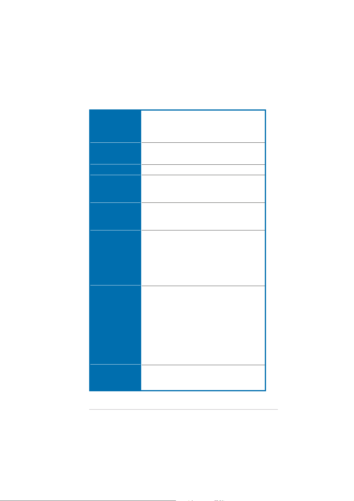
CPUCPU
CPU
CPUCPU
ChipsetChipset
Chipset
ChipsetChipset
Front Side BusFront Side Bus
Front Side Bus
Front Side BusFront Side Bus
MemoryMemory
Memory
MemoryMemory
Expansion slotsExpansion slots
Expansion slots
Expansion slotsExpansion slots
Scalable LinkScalable Link
Scalable Link
Scalable LinkScalable Link
Interface (SLI™)Interface (SLI™)
Interface (SLI™)
Interface (SLI™)Interface (SLI™)
Socket 939 for AMD Athlon™ 64 FX/64 X2/64 and
Sempron™ processor
Supports AMD 64 architecture that enables
simultaneous 32-bit and 64-bit computing
Supports AMD Cool ‘n’ Quiet! Technology
NVIDIA® nForce4 SLI x16
Northbridge: NVIDIA® nForce™ SPP 100
Southbridge: NVIDIA® nForce4 SLI
1600/2000 MT per second
Dual-channel memory architecture
4 x 184-pin DIMM sockets support unbufferred ECC/
non-ECC DDR400/333/266 memory modules
Supports up to 4 GB system memory
2 x PCI Express™ x16 slots with Scalable Link Interface
(SLI™) support at full x16, x16 mode
1 x PCI Express x4 slot (supports x4/x1 card)
3 x PCI slots
SLI™ mode supports:
- 2 x identical SLI™-ready PCI Express™ x16 graphics
ASUS Soft SLI Bridge
ASUS EZ Plug™
ASUS PEG Link for dual PCI Express graphics cards
ASUS Two-slot thermal design
(PCI 2.2)
NoteNote
cards (
N o te: In SLI mode, the PCI Express x16 slots work
NoteNote
at the full bandwidth of x16 each, for a combined
bandwidth of x32.
)
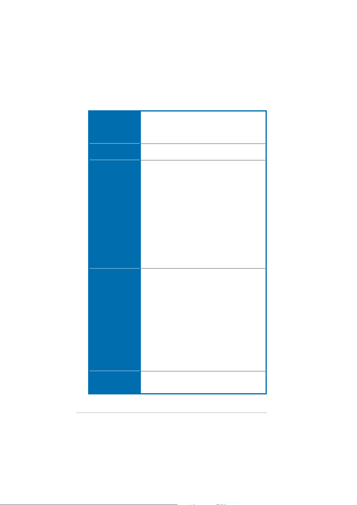
StorageStorage
Storage
StorageStorage
USBUSB
USB
USBUSB
NVIDIA® nForce4 SLI supports:
- 2 x Ultra DMA 133/100/66/33 connectors
for up to four IDE devices
- 4 x Serial ATA devices (3 Gb/s)
- NVRAID for RAID 0, RAID 1, RAID 0+1, RAID 5, and
JBOD configuration that spans across Serial ATA
drives
Silicon Image® 3132 SATA controller supports:
- 1 x Internal Serial ATA device (3 Gb/s)
- 1 x External Serial ATA device (3 Gb/s)
(for SATA On-The-Go)
- RAID 0 and RAID 1 configurations
Deluxe/WiFi : Supports up to 9 USB 2.0 ports
Deluxe : Supports up to 10 USB 2.0 ports
(continued on the next page)
xixi
xi
xixi
A8N32-SLI Deluxe specifications summary
AI AudioAI Audio
AI Audio
AI AudioAI Audio
IEEE 1394IEEE 1394
IEEE 1394
IEEE 1394IEEE 1394
Realtek® ALC850 8-channel CODEC
1 x Coaxial S/PDIF out port
1 x Optical S/PDIF out port
Supports Universal Audio Jack (UAJ®) Technology
Supports Audio Sensing and Enumeration Technology
TI® 1394a controller supports 2 x IEEE 1394a
connectors at midboard
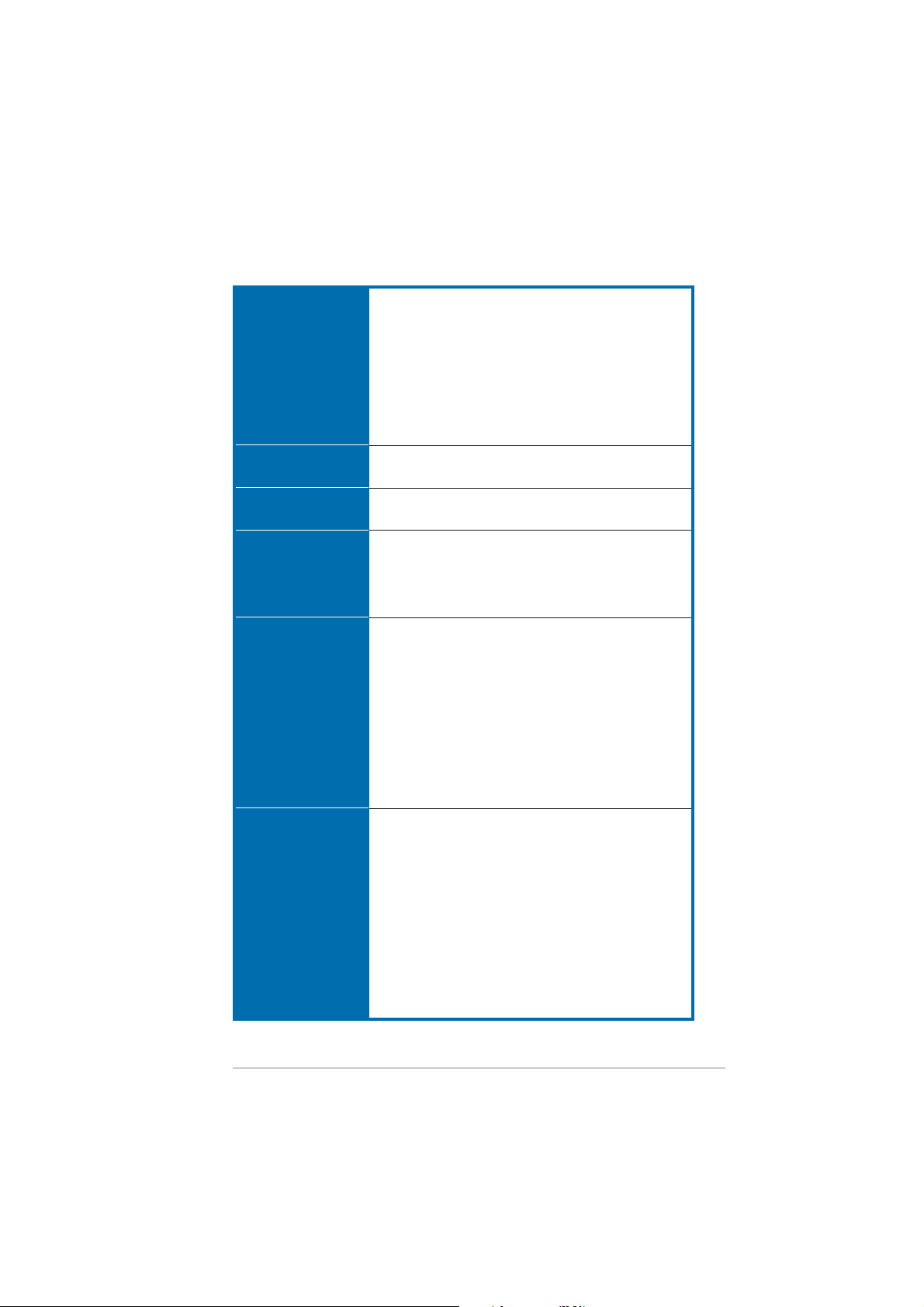
NetworkNetwork
Network
NetworkNetwork
ASUS ExclusiveASUS Exclusive
ASUS Exclusive
ASUS ExclusiveASUS Exclusive
OverclockingOverclocking
Overclocking
OverclockingOverclocking
featuresfeatures
features
featuresfeatures
LAN:LAN:
LAN:
LAN:LAN:
Marvell® PCI Express Gigabit LAN controller
Marvell® Gigabit LAN PHY
NVIDIA® nForce4 SLI built-in Gigabit MAC with external
Marvell Gigabit LAN PHY supports:
- NV ActiveArmor
- NV Firewall
- NV RIS (Remote Installation Service)
- AI NET
Wireless: Wireless:
Wireless: (On Deluxe/WiFi models only)
Wireless: Wireless:
Realtek® RTL8187L IEEE 802.11b/g 54 Mbps wireless
LAN adapter supports:
- Software Access Point (Windows® 2000/XP/2003)
- Client/Ad-hoc mode
- One-touch wizard
- Wake on Wireless LAN ready
- External antenna for optimum coverage
Intelligent overclocking tools:
- AI NOS™ (Non-delay Overclocking System)
- AI Overclocking (intelligent CPU frequency tuner)
- ASUS PEG Link (automatic performance tuning for
single/dual graphics cards)
- ASUS AI Booster Utility
Precision Tweaker supports:
- DIMM voltage: 13-step DRAM voltage control
- Core voltage: Adjustable CPU voltage at 0.0125 V
increment
Stepless Frequency Selection(SFS) allows:
- FSB tuning from 200 MHz to 400 MHz at 1 MHz increment
- Memory tuning from 400 MHz to 800 MHz
- PCI Express frequency tuning from 100 MHz to
200 MHz at 1 MHz increment
Overclocking protection:
- ASUS C.P.R. (CPU Parameter Recall)
ASUS AI LifeASUS AI Life
ASUS AI Life
ASUS AI LifeASUS AI Life
featuresfeatures
features
featuresfeatures
xiixii
xii
xiixii
Stack Cool 2
ASUS SATA On-The-Go (External Serial ATA port on the
rear panel
(continued on the next page)
A8N32-SLI Deluxe specifications summary
Other ASUSOther ASUS
Other ASUS
Other ASUSOther ASUS
special featuresspecial features
special features
special featuresspecial features
ManageabilityManageability
Manageability
ManageabilityManageability
BIOS featuresBIOS features
BIOS features
BIOS featuresBIOS features
PowerPower
Power
PowerPower
RequirementRequirement
Requirement
RequirementRequirement
Rear panelRear panel
Rear panel
Rear panelRear panel
ASUS 8-Phase Power Design
ASUS Fanless Design
ASUS AI Overclocking (Intelligent CPU frequency tuner)
AI NET network diagnosis
ASUS CrashFree BIOS 2
ASUS Q-Fan2
ASUS MyLogo2
ASUS EZ Flash
ASUS Multi-language BIOS
ASUS C.P.R. (CPU Parameter Recall)
WfM2.0, DMI2.0, WOL by PME, Wake on Wireless LAN
(Deluxe/WiFi model only), PXE, RPL
8 Mb Flash ROM, AMI BIOS, PnP, DMI2.0, SM BIOS 2.3,
WfM2.0
ATX power supply (with 24-pin and 4-pin 12 V plugs)
ATX 12 V 2.0 compliant
ASUS EZ Plug (
When using two graphics cards and a
20-pin ATX PSU or, if the two graphics cards do not
have auxiliary power.
1 x Parallel port
2 x LAN (RJ-45) ports
USB 2.0 ports (5 ports on Deluxe/WiFi model; 4 ports
on Deluxe model)
1 x Wireless LAN antenna port (Deluxe/WiFi model only)
1 x Wireless LAN activity LED (Deluxe/WiFi model only)
1 x External Serial ATA port
1 x Optical S/PDIF Out port
1 x Coaxial S/PDIF Out port
1 x PS/2 keyboard port (purple)
1 x PS/2 mouse port (green)
8-channel audio ports
)
InternalInternal
Internal
InternalInternal
connectorsconnectors
connectors
connectorsconnectors
1 x Floppy disk drive connector
2 x IDE connectors
4 x NVIDIA nForce4 Serial ATA connectors
1 x Silicon Image Serial ATA connector
1 x Serial port connector
1 x 24-pin ATX power connector
1 x 4-pin ATX 12 V power connector
1 x 4-pin ASUS EZ Plug™ connector
3 x USB connectors for additional six USB 2.0 ports
(4 x USB 2.0 ports on Deluxe/WiFi model)
1 x CD IN/AUX connector
2 x IEEE 1394a connectors
1 x GAME/MIDI connector
1 x Chassis intrusion connector
(continued on the next page)
xiiixiii
xiii
xiiixiii
A8N32-SLI Deluxe specifications summary
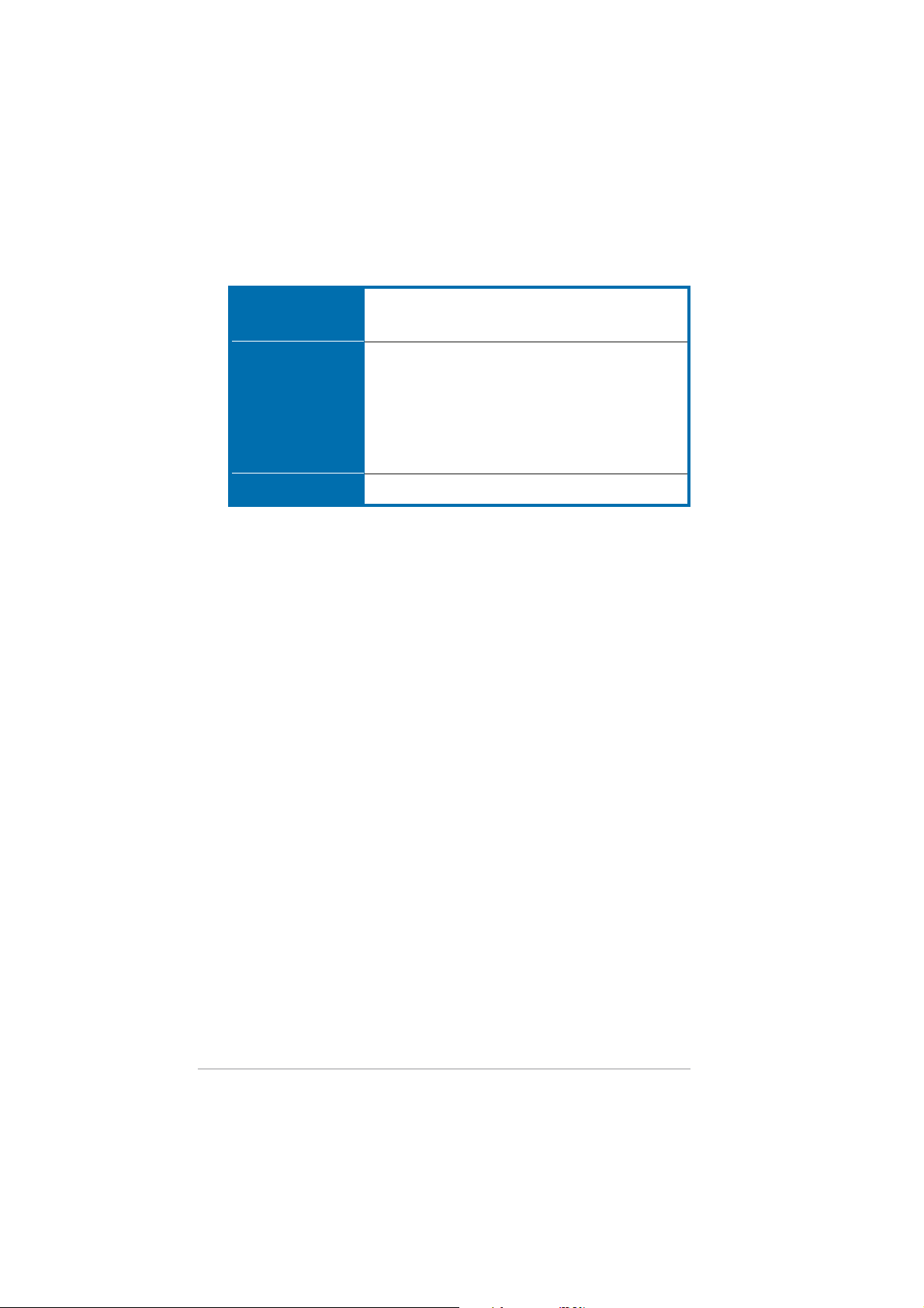
InternalInternal
Internal
InternalInternal
connectorsconnectors
connectors
connectorsconnectors
continuationcontinuation
continuation
continuationcontinuation
Support CDSupport CD
Support CD
Support CDSupport CD
contentscontents
contents
contentscontents
Form FactorForm Factor
Form Factor
Form FactorForm Factor
*Specifications are subject to change without notice.
1 x Front panel audio connector
CPU, Chassis (x2), Chipset (x2), Power fan connectors
System panel connector
Device drivers
ASUS PC Probe II
ASUS Update
ASUS AI Booster
NV RIS
NV Firewall
NV RAID
Anti-Virus Utility (OEM version)
ATX form factor: 12 in x 9.6 in (30.5 cm x 24.5 cm)
xivxiv
xiv
xivxiv

This chapter describes the motherboard
features and the new technologies
it supports.
introduction
Product
1

Chapter summary
1
1.1 Welcome! .............................................................................. 1-1
1.2 Package contents ................................................................. 1-1
1.3 Special features .................................................................... 1-2
ASUS A8N32-SLI DeluxeASUS A8N32-SLI Deluxe
ASUS A8N32-SLI Deluxe
ASUS A8N32-SLI DeluxeASUS A8N32-SLI Deluxe

1.1 Welcome!
®®
®
Thank you for buying an ASUSThank you for buying an ASUS
Thank you for buying an ASUS
Thank you for buying an ASUSThank you for buying an ASUS
Deluxe Deluxe
Deluxe
Deluxe Deluxe
motherboard!motherboard!
motherboard!
motherboard!motherboard!
®®
A8A8
NN
33
2-SLI 2-SLI
A8
A8A8
N
3
NN
33
Deluxe/WiFi orDeluxe/WiFi or
2-SLI
Deluxe/WiFi or
2-SLI 2-SLI
Deluxe/WiFi orDeluxe/WiFi or
The motherboard delivers a host of new features and latest technologies,
making it another standout in the long line of ASUS quality motherboards!
Before you start installing the motherboard, and hardware devices on it,
check the items in your package with the list below.
1.2 Package contents
Check your motherboard package for the following items.
MotherboardMotherboard
Motherboard ASUS A8N32-SLI Deluxe/WiFi or
MotherboardMotherboard
I/O modulesI/O modules
I/O modules 1 x 2-port IEEE1394a module
I/O modulesI/O modules
CablesCables
Cables Serial ATA cables for 5 devices
CablesCables
AccessoriesAccessories
Accessories Wireless LAN antenna (Deluxe/Wi-Fi model only)
AccessoriesAccessories
Application CDsApplication CDs
Application CDs ASUS motherboard support CD
Application CDsApplication CDs
DocumentationDocumentation
Documentation User guide
DocumentationDocumentation
ASUS A8N32-SLI Deluxe motherboard
1 x Serial port module
1 x 2-port USB 2.0/GAME module
Serial ATA power cables for 5 devices
1 x Ultra DMA 133/100/66 cable
1 x IDE cable
1 x Floppy disk drive cable
I/O shield
ASUS Soft SLI Bridge
InterVideo® WinDVD® Suite (Retail version only)
If any of the above items is damaged or missing, contact your retailer.
ASUS A8N32-SLI DeluxeASUS A8N32-SLI Deluxe
ASUS A8N32-SLI Deluxe
ASUS A8N32-SLI DeluxeASUS A8N32-SLI Deluxe
1-11-1
1-1
1-11-1

1.3 Special features
1.3.11.3.1
1.3.1
1.3.11.3.1
Latest processor technology Latest processor technology
Latest processor technology
Latest processor technology Latest processor technology
The AMD Athlon™ 64FX, 64 X2, and 64 desktop processors are based on
AMD’s 64-bit and 32-bit architecture, which represents the landmark
introduction of the industry’s first x86-64 technology. These processors
provide a dramatic leap forward in compatibility, performance, investment
protection, and reduced total cost of ownership and development.
See page 2-7.
NVIDIA nForce4 SLI x16 chipset NVIDIA nForce4 SLI x16 chipset
NVIDIA nForce4 SLI x16 chipset
NVIDIA nForce4 SLI x16 chipset NVIDIA nForce4 SLI x16 chipset
The motherboard features the NVIDIA® nForce4® SLI chipset that supports
not one, but two full bandwidth x16 PCI Express lanes for an ultimate visual
and graphics experience. The chipset’s low latency architecture provides
the best core logic solution for performance desktop computers.
Scalable Link Interface (SLI™) technology Scalable Link Interface (SLI™) technology
Scalable Link Interface (SLI™) technology
Scalable Link Interface (SLI™) technology Scalable Link Interface (SLI™) technology
The NVIDIA® nForce4® Scalable Link Interface (SLI™) technology allows two
graphics processing units (GPUs) in a single system. This technology takes
advantage of the PCI Express™ bus architecture and features intelligent
hardware and software solutions that allows multiple GPUs to work together
and achieve exceptional graphics performance.
Built-in NVFirewall™ and NVActiveArmor™ Built-in NVFirewall™ and NVActiveArmor™
Built-in NVFirewall™ and NVActiveArmor™
Built-in NVFirewall™ and NVActiveArmor™ Built-in NVFirewall™ and NVActiveArmor™
The NVIDIA® Firewall™ (NVFirewall™) is an easy-to-use high-performance
desktop firewall application that protects your system from intruders.
Integrated into the NVIDIA® nForce4® SLI™ chipset with the NVIDIA® Gigabit
Ethernet, it provides advanced anti-computer-hacking technologies, remote
management capabilities, and a user-friendly setup wizard that improves
overall system security.
Enhancing your network security is the NVIDIA
(NV ActiveArmor™) engine that provides advanced data packet inspection.
This innovative technology ensures that only safe data packets are passed
on the network. It boosts overall system performance by offloading the CPU
from the rigorous task of filtering data packets.
Product highlightsProduct highlights
Product highlights
Product highlightsProduct highlights
®
ActiveArmor™
AMD Cool ‘n’ Quiet!™ Technology AMD Cool ‘n’ Quiet!™ Technology
AMD Cool ‘n’ Quiet!™ Technology
AMD Cool ‘n’ Quiet!™ Technology AMD Cool ‘n’ Quiet!™ Technology
The motherboard supports the AMD Cool ‘n’ Quiet!™ Technology that
dynamically and automatically changes the CPU speed, voltage and amount of
power depending on the task the CPU performs. See pages 4-20 for details.
1-21-2
1-2
1-21-2
Chapter 1: Product introductionChapter 1: Product introduction
Chapter 1: Product introduction
Chapter 1: Product introductionChapter 1: Product introduction
HyperTransport™ Technology HyperTransport™ Technology
HyperTransport™ Technology
HyperTransport™ Technology HyperTransport™ Technology
HyperTransport™ Technology is a high-speed, low latency, point-to-point
link designed to increase the communication speed between integrated
circuits in computers, networking and telecommunicatons equipment up to
48 times faster than other existing technologies.
Dual Channel DDR memory support Dual Channel DDR memory support
Dual Channel DDR memory support
Dual Channel DDR memory support Dual Channel DDR memory support
Employing the Double Data Rate (DDR) memory technology, the
motherboard supports up to 4 GB of system memory using DDR400/333/
266 DIMMs. The ultra-fast 400 MHz memory bus delivers the required
bandwidth for the latest 3D graphics, multimedia, and Internet applications.
See page 2-12.
Serial ATA 3Gb/s technology Serial ATA 3Gb/s technology
Serial ATA 3Gb/s technology
Serial ATA 3Gb/s technology Serial ATA 3Gb/s technology
The motherboard supports the Serial ATA 3 Gb/s technology through the
Silicon Image Serial ATA interfaces and the NVIDIA® nForce4 x16 SLI
chipset. The Serial ATA 3 Gb/s specification provides twice the bandwidth of
the current Serial ATA products with a host of new features, including Native
Command Queuing (NCQ), Power Management (PM) Implementation
Algorithm, and Hot Swap. Serial ATA allows thinner, more flexible cables
with lower pin count and reduced voltage requirements.
Dual RAID solution Dual RAID solution
Dual RAID solution
Dual RAID solution Dual RAID solution
Onboard RAID controllers provide the motherboard with dual-RAID
functionality that allows you to select the best RAID solution using Serial
ATA devices.
®
The NVIDIA
JBOD configuration for four SATA 3Gb/s. See page 2-25 for details.
The Silicon Image
3Gb/s connectors and allows RAID 0 and RAID 1 configurations through the
internal and external Serial ATA ports. See page 2-26 for details.
nForce4® SLI™ allows RAID 0, RAID 1, RAID 0+1, RAID 5, and
®
3132 controller supports two additional Serial ATA
Dual Gigabit LAN solution Dual Gigabit LAN solution
Dual Gigabit LAN solution
Dual Gigabit LAN solution Dual Gigabit LAN solution
The motherboard comes with dual Gigabit LAN controllers to provide the total
solution for your networking needs. These network controllers use the PCI
Express segment to provide faster data bandwidth for your wired or wireless
Internet, LAN, and file sharing requirements. See page 2-22 for details.
ASUS A8N32-SLI DeluxeASUS A8N32-SLI Deluxe
ASUS A8N32-SLI Deluxe
ASUS A8N32-SLI DeluxeASUS A8N32-SLI Deluxe
1-31-3
1-3
1-31-3

Wireless LAN solution Wireless LAN solution
Wireless LAN solution
Wireless LAN solution Wireless LAN solution
The motherboard comes with the Realtek® RTL8187L LAN controller for
the onboard wireless LAN module that supports IEEE 802.11 b/g
standards, allowing data transmission of up to 54 Mbps using the 2.4 GHz/
5 GHz frequency band. ASUS provides a user-friendly wizard that helps you
set up your wireless local area network effortlessly. See page 5-21 for
details.
PCI Express™ interface PCI Express™ interface
PCI Express™ interface
PCI Express™ interface PCI Express™ interface
The motherboard fully supports PCI Express, the latest I/O interconnect
technology that speeds up the PCI bus. PCI Express features point-to-point
serial interconnections between devices and allows higher clockspeeds by
carrying data in packets. This high speed interface is software compatible with
existing PCI specifications. See page 2-19 for details.
S/PDIF digital sound ready S/PDIF digital sound ready
S/PDIF digital sound ready
S/PDIF digital sound ready S/PDIF digital sound ready
The motherboard supports the S/PDIF technology through the S/PDIF
interfaces on the rear panel. The S/PDIF technology turns your computer into
a high-end entertainment system with digital connectivity to powerful audio
and speaker systems. See page 2-23 for details.
IEEE 1394a support IEEE 1394a support
IEEE 1394a support
IEEE 1394a support IEEE 1394a support
The IEEE 1394a interface provides high-speed and flexible PC connectivity
to a wide range of peripherals and devices compliant to the IEEE 1394a
standard. The IEEE 1394a interface allows up to 400 Mbps transfer rates
through simple, low-cost, high-bandwidth asynchronous (real-time) data
interfacing between computers, peripherals, and consumer electronic
devices such as camcorders, VCRs, printers, TVs, and digital cameras.
See page 2-28 for details.
(on Deluxe/WiFi model only)
USB 2.0 technology USB 2.0 technology
USB 2.0 technology
USB 2.0 technology USB 2.0 technology
The motherboard implements the Universal Serial Bus (USB) 2.0
specification, dramatically increasing the connection speed from the
12 Mbps bandwidth on USB 1.1 to a fast 480 Mbps on USB 2.0. USB 2.0 is
backward compatible with USB 1.1. See pages 2-22 and 2-27 for details.
1-41-4
1-4
1-41-4
Chapter 1: Product introductionChapter 1: Product introduction
Chapter 1: Product introduction
Chapter 1: Product introductionChapter 1: Product introduction
1.3.21.3.2
1.3.2
1.3.21.3.2
8-Phase Power Design 8-Phase Power Design
8-Phase Power Design
8-Phase Power Design 8-Phase Power Design
The motherboard features an 8-phase power module, with each module
sharing the total power requirement of the CPU. A single module takes
about half of a 4-phase power module load. This results to less heat, longer
lifespan for the CPU, and a more stable operation.
Fanless Design Fanless Design
Fanless Design
Fanless Design Fanless Design
The ASUS fanless design allows multi-directional heat flow from major
thermal sources in the motherboard to lower overall system temperature,
resulting in quieter operation and longer system life.
Heatpipe Heatpipe
Heatpipe
Heatpipe Heatpipe
The Heatpipe that passes through motherboard components effectively
transfers the heat away from the components. Because the copper
heatpipe is a fanless innovation, users are guaranteed of a quiet computing
environment and of a cost-effective cooling solution.
Stack Cool 2 Stack Cool 2
Stack Cool 2
Stack Cool 2 Stack Cool 2
Innovative ASUS featuresInnovative ASUS features
Innovative ASUS features
Innovative ASUS featuresInnovative ASUS features
The motherboard comes with the ASUS Stack Cool 2, an innovative
fan-less and zero-noise thermal solution that provides supplementary
cooling to the motherboard. Stack Cool 2 is a special layer underneath the
motherboard that improves heat dissipation.
SATA-On-The-Go SATA-On-The-Go
SATA-On-The-Go
SATA-On-The-Go SATA-On-The-Go
Leveraging the Serial ATA II feature is the SATA-On-The-Go. This external
port on the rear panel I/O provides smart setup, hot-plug and support for
up to 16 devices with port-multiplier functions. See pages 2-23 for details.
AI NOS™ (Non-Delay Overclocking System) AI NOS™ (Non-Delay Overclocking System)
AI NOS™ (Non-Delay Overclocking System)
AI NOS™ (Non-Delay Overclocking System) AI NOS™ (Non-Delay Overclocking System)
ASUS Non-delay Overclocking System™ (NOS) is a technology that
auto-detects the CPU loading and dynamically overclocks the CPU speed
only when needed.
ASUS A8N32-SLI DeluxeASUS A8N32-SLI Deluxe
ASUS A8N32-SLI Deluxe
ASUS A8N32-SLI DeluxeASUS A8N32-SLI Deluxe
1-51-5
1-5
1-51-5

Precision Tweaker Precision Tweaker
Precision Tweaker
Precision Tweaker Precision Tweaker
This feature allows you to fine tune the CPU/memory voltage and gradually
increase the memory Front Side Bus (FSB) and PCI Express frequency at
1MHz increment to achieve maximum system performance.
PEG Link Mode for two graphics cards PEG Link Mode for two graphics cards
PEG Link Mode for two graphics cards
PEG Link Mode for two graphics cards PEG Link Mode for two graphics cards
This feature enhances your PCI Express graphics card performance. It allows
the motherboard to automatically adjust the PCI Express graphics link mode
to the correct frequency based on the system configuration. Four
additional settings are available for overclocking the PEG Link Mode. See
page 4-22 for details.
AI NET AI NET
AI NET
AI NET AI NET
AI NET is a BIOS-based diagnostic tool that detects and reports Ethernet
cable faults and shorts. With this utility, you can easily monitor the
condition of the Ethernet cable(s) connected to the Marvell
port.
ASUS Two-slot thermal designASUS Two-slot thermal design
ASUS Two-slot thermal design
ASUS Two-slot thermal designASUS Two-slot thermal design
The motherboard is designed with two PCI slots placed between the PCI
Express x16 slots, allowing increased airflow between the two PCI Express
x16 graphics cards. This special design permits more room for ventilation,
thus lowering the overall system temperature.
®
LAN (RJ-45)
CrashFree BIOS 2 CrashFree BIOS 2
CrashFree BIOS 2
CrashFree BIOS 2 CrashFree BIOS 2
This feature allows you to restore the original BIOS data from the support CD
in case when the BIOS codes and data are corrupted. This protection
eliminates the need to buy a replacement ROM chip. See page 4-5 for details.
1-61-6
1-6
1-61-6
Chapter 1: Product introductionChapter 1: Product introduction
Chapter 1: Product introduction
Chapter 1: Product introductionChapter 1: Product introduction

ASUS Q-Fan 2 technology ASUS Q-Fan 2 technology
ASUS Q-Fan 2 technology
ASUS Q-Fan 2 technology ASUS Q-Fan 2 technology
The ASUS Q-Fan 2 technology smartly adjusts the CPU and chassis fan 1
speeds according to the system loading to ensure quiet, cool, and efficient
operation. See page 4-36 for details.
ASUS Multi-language BIOS ASUS Multi-language BIOS
ASUS Multi-language BIOS
ASUS Multi-language BIOS ASUS Multi-language BIOS
The multi-language BIOS allows you to select the language of your choice
from the available options. The localized BIOS menus allow easier and faster
configuration. See page 4-14 for details.
ASUS MyLogo2™ ASUS MyLogo2™
ASUS MyLogo2™
ASUS MyLogo2™ ASUS MyLogo2™
This new feature present in the motherboard allows you to personalize and
add style to your system with customizable boot logos.
ASUS EZ Plug™ ASUS EZ Plug™
ASUS EZ Plug™
ASUS EZ Plug™ ASUS EZ Plug™
This patented ASUS technology is a 4-pin auxiliary +12V connector that is
designed to maintain the voltage integrity of your system. This plug
guarantees adequate supply of power to the motherboard and other
installed peripherals. See page 2-32 for the illustration.
C.P.R. (CPU Parameter Recall) C.P.R. (CPU Parameter Recall)
C.P.R. (CPU Parameter Recall)
C.P.R. (CPU Parameter Recall) C.P.R. (CPU Parameter Recall)
The C.P.R. feature of the motherboard BIOS allows automatic re-setting to
the BIOS default settings in case the system hangs due to overclocking.
When the system hangs due to overclocking, C.P.R. eliminates the need to
open the system chassis and clear the RTC data. Simply shut down and
reboot the system, and the BIOS automatically restores the CPU default
setting for each parameter.
ASUS EZ Flash BIOS ASUS EZ Flash BIOS
ASUS EZ Flash BIOS
ASUS EZ Flash BIOS ASUS EZ Flash BIOS
With the ASUS EZ Flash, you can easily update the system BIOS even
before loading the operating system. No need to use a DOS-based utility or
boot from a floppy disk. See page 4-7 for details.
ASUS A8N32-SLI DeluxeASUS A8N32-SLI Deluxe
ASUS A8N32-SLI Deluxe
ASUS A8N32-SLI DeluxeASUS A8N32-SLI Deluxe
1-71-7
1-7
1-71-7

1-81-8
1-8
1-81-8
Chapter 1: Product introductionChapter 1: Product introduction
Chapter 1: Product introduction
Chapter 1: Product introductionChapter 1: Product introduction

This chapter lists the hardware setup
procedures that you have to perform
when installing system components.
It includes description of the jumpers
and connectors on the motherboard.
information
Hardware
2

Chapter summary
2
2.1 Before you proceed .............................................................. 2-1
2.2 Motherboard overview .......................................................... 2-2
2.3 Central Processing Unit (CPU) .............................................. 2-7
2.4 System memory ................................................................. 2-12
2.5 Expansion slots ................................................................... 2-17
2.6 Jumper ............................................................................... 2-20
2.7 Connectors .........................................................................2-21
ASUS A8N32-SLI DeluxeASUS A8N32-SLI Deluxe
ASUS A8N32-SLI Deluxe
ASUS A8N32-SLI DeluxeASUS A8N32-SLI Deluxe
2.1 Before you proceed
Take note of the following precautions before you install motherboard
components or change any motherboard settings.
• Unplug the power cord from the wall socket before touching any
component.
• Use a grounded wrist strap or touch a safely grounded object or to
a metal object, such as the power supply case, before handling
components to avoid damaging them due to static electricity.
• Hold components by the edges to avoid touching the ICs on them.
• Whenever you uninstall any component, place it on a grounded
antistatic pad or in the bag that came with the component.
Before you install or remove any component, ensureBefore you install or remove any component, ensure
•
Before you install or remove any component, ensure
Before you install or remove any component, ensureBefore you install or remove any component, ensure
that the ATX power supply is switched off or thethat the ATX power supply is switched off or the
that the ATX power supply is switched off or the
that the ATX power supply is switched off or thethat the ATX power supply is switched off or the
power cord is detached from the power supply. power cord is detached from the power supply.
power cord is detached from the power supply. Failure
power cord is detached from the power supply. power cord is detached from the power supply.
to do so may cause severe damage to the motherboard, peripherals,
and/or components.
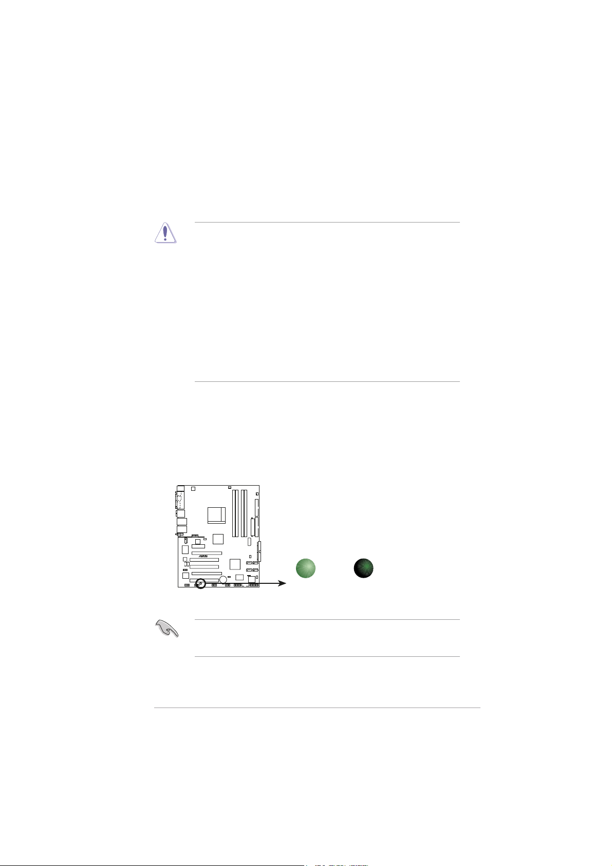
Onboard LEDOnboard LED
Onboard LED
Onboard LEDOnboard LED
The motherboard comes with a standby power LED. The green LED lights
up to indicate that the system is ON, in sleep mode, or in soft-off mode.
This is a reminder that you should shut down the system and unplug the
power cable before removing or plugging in any motherboard component.
The illustration below shows the location of the onboard LED.
A8N32-SLI
®
A8N32-SLI Onboard LED
Make sure to connect the EZPlug when using two PCI Express graphics
cards and a 20-pin ATX power supply unit, or if the graphics cards do
not have auxiliary power plugs.
ASUS A8N32-SLI DeluxeASUS A8N32-SLI Deluxe
ASUS A8N32-SLI Deluxe
ASUS A8N32-SLI DeluxeASUS A8N32-SLI Deluxe
ON
Standby
Power
SB_PWR
OFF
Powered
Off
2-12-1
2-1
2-12-1
2.2 Motherboard overview
Before you install the motherboard, study the configuration of your chassis
to ensure that the motherboard fits into it.
Make sure to unplug the power cord before installing or removing the
motherboard. Failure to do so can cause you physical injury and damage
motherboard components.
2.2.12.2.1
2.2.1
2.2.12.2.1
Placement directionPlacement direction
Placement direction
Placement directionPlacement direction
When installing the motherboard, make sure that you place it into the
chassis in the correct orientation. The edge with external ports goes to the
rear part of the chassis as indicated in the image below.
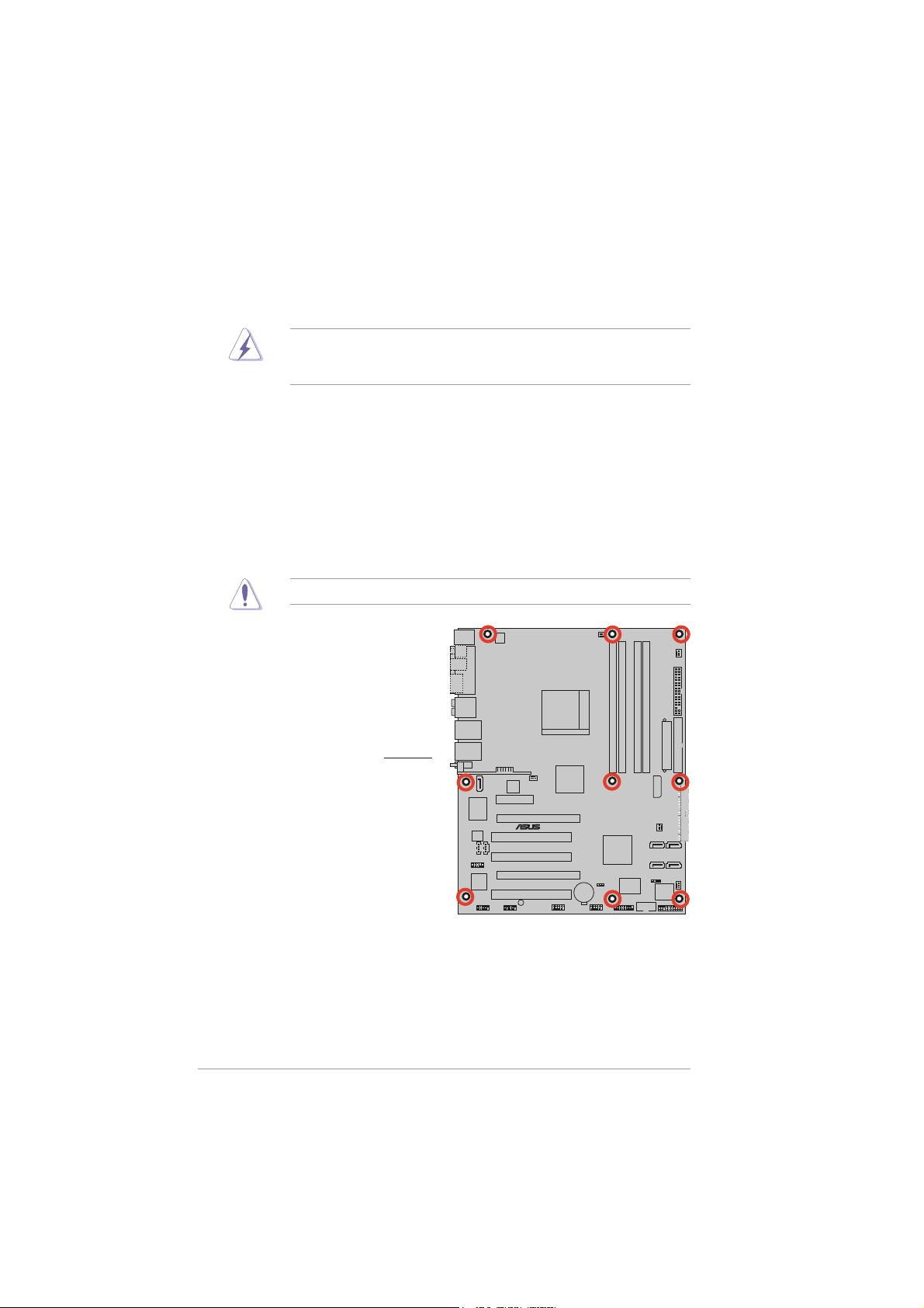
2.2.22.2.2
2.2.2
2.2.22.2.2
Screw holesScrew holes
Screw holes
Screw holesScrew holes
Place nine (9) screws into the holes indicated by circles to secure the
motherboard to the chassis.
Do not overtighten the screws! Doing so can damage the motherboard.
A8N32-SLI
Place this side towardsPlace this side towards
Place this side towards
Place this side towardsPlace this side towards
the rear of the chassisthe rear of the chassis
the rear of the chassis
the rear of the chassisthe rear of the chassis
®
2-22-2
2-2
2-22-2
Chapter 2: Hardware informationChapter 2: Hardware information
Chapter 2: Hardware information
Chapter 2: Hardware informationChapter 2: Hardware information
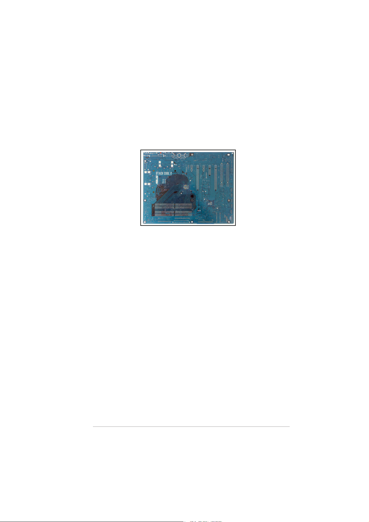
2.2.32.2.3
2.2.3
2.2.32.2.3
The motherboard comes with the ASUS Stack Cool 2 cooling solution that
lowers the temperature of critical heat generating components. The
motherboard uses a special design on the printed circuit board (PCB) to
dissipate heat that critical components generate.
ASUS Stack Cool 2ASUS Stack Cool 2
ASUS Stack Cool 2
ASUS Stack Cool 2ASUS Stack Cool 2
ASUS A8N32-SLI DeluxeASUS A8N32-SLI Deluxe
ASUS A8N32-SLI Deluxe
ASUS A8N32-SLI DeluxeASUS A8N32-SLI Deluxe
2-32-3
2-3
2-32-3
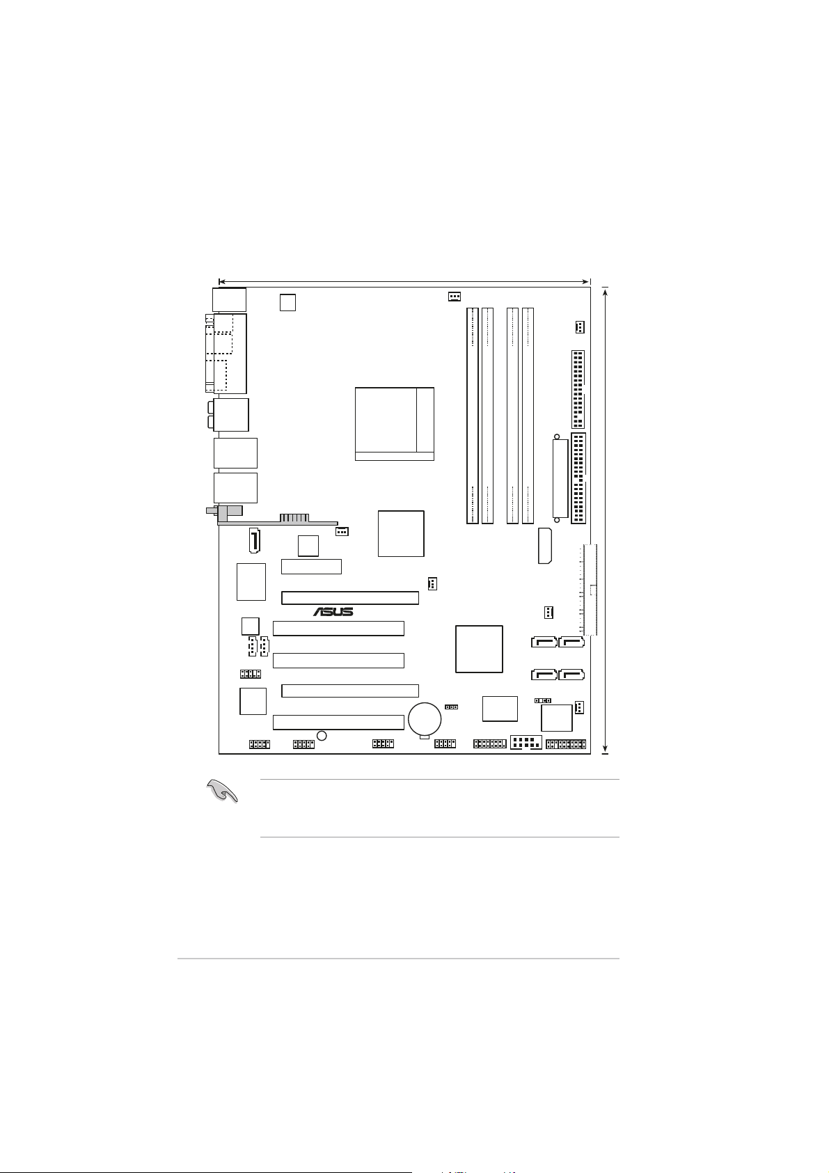
2.2.42.2.4
2.2.4
2.2.42.2.4
PS/2KBMS
T: Mouse
B: Keyboard
SPDIF_O
SPDIF_O2
ESATA
Motherboard layoutMotherboard layout
Motherboard layout
Motherboard layoutMotherboard layout
24.5cm (9.6in)
ATX12V
PARALLEL PORT
CPU_FAN
PWR_FAN
AUDIO
LAN1_USB12
LAN2_USB34
WIFI_G_USB10(USB910)
SATA_RAID2
ACL850
CD
TSB43AB22A
FLOPPY
Socket 939
A8N32-SLI
DDR DIMM_B2 (64 bit,184-pin module)
DDR DIMM_B1 (64 bit,184-pin module)
DDR DIMM_A1 (64 bit,184-pin module)
DDR DIMM_A2 (64 bit,184-pin module)
EATXPWR
®
NVIDIA
C51D
®
NB_FAN
CR2032 3V
Lithium Cell
CMOS Power
®
NVIDIA
CK804
SLI
CHASSIS
Super
CLRTC
I/O
COM1
GAME
USB78USB56
EZ_PLUG
SB_FAN
8Mb
BIOS
SATA1SATA2
SATA4SATA3
PANEL
SEC_IDE
CHA_FAN2
PHY
Marvell
IE1394_1
AUX
FP_AUDIO
Marvell
PCIE LAN
PCIEX4_1
IE1394_2
CHA_FAN1
PCIEX16_1
PCI1
PCI2
PCIEX16_2
PCI3
SB_PWR
• Grayed out components are available only on Deluxe/WiFi model.
• On Deluxe/WiFi model, the onboard WiFi and the rear panel USB9
port use the USB910 connector.
30.5cm (12.0in)
PRI_IDE
2-42-4
2-4
2-42-4
Chapter 2: Hardware informationChapter 2: Hardware information
Chapter 2: Hardware information
Chapter 2: Hardware informationChapter 2: Hardware information
 Loading...