

Page 1
IE1010
®
A7V333 Updates
This insert updates the specifications for the A7V333. (Revisions refer to
pages 14, 15, 18, 31, 28, 67 and 87 of the manual.)
~ Three (3) sockets are available for both 266MHz-PC2100 or 200MHzPC1600 DDR DIMMs to form a memory size of 64MB to 3GB. Only two (2)
DIMMs will support 333MHz-PC2700; if more than two 333MHz DIMMs are
installed, the system automatically reverts to a maximum speed of 266MHz.
2.5.2 Memory configurations (page 14, 15)
Install DIMMs in any of the following combinations.
DIMM Location 168-pin DIMM (SDR) Total Memory
Socket 1 (Rows 0&1) 64MB, 128MB, 256MB, 512MB, 1GB x1
Socket 2 (Rows 2&3) 64MB, 128MB, 256MB, 512MB, 1GB x1
Socket 3 (Rows 4&5) 64MB, 128MB, 256MB, 512MB, 1GB x1
Total system memory (Max. 3GB PC2100 / PC1600) =
(Max. 2GB PC2700)
2.5.3 DDR333 DIMM Qualified Vendor List
The following table lists the PC2700 - DDR333 memory modules that have
been tested and qualified for use with this motherboard.
Vendor Model Type/Size
Nanya NT5DS16M8AT-6 PC2700/256MB
Samsung K4H280838D-TCB3 PC2700/128MB
Samsung K4H280838D-TCB3 PC2700/256MB
Micron MT8VDDT1664AG-335B1 PC2700/128MB
Micron MT16VDDT3264AG-335B1 PC2700/256MB
KINGMAX MPMA82D-68KX3 PC2700/128MB
KINGMAX MPM62D-68KX3 PC2700/256MB
Use only the tested and qualified PC2700 - DDR333 DIMMs listed
above. Other DDR DIMMs manufactured by other vendors may not be
suitable for this motherboard. Visit the ASUS website for the latest
qualified DDR module list.
ASUS A7V333 Technical Updates
1
Page 2
®
A7V333 Updates
Because of local distribution and marketing issues, the A7V333 may adopt
the AGP Pro slot or a universal AGP4X slot onboard:
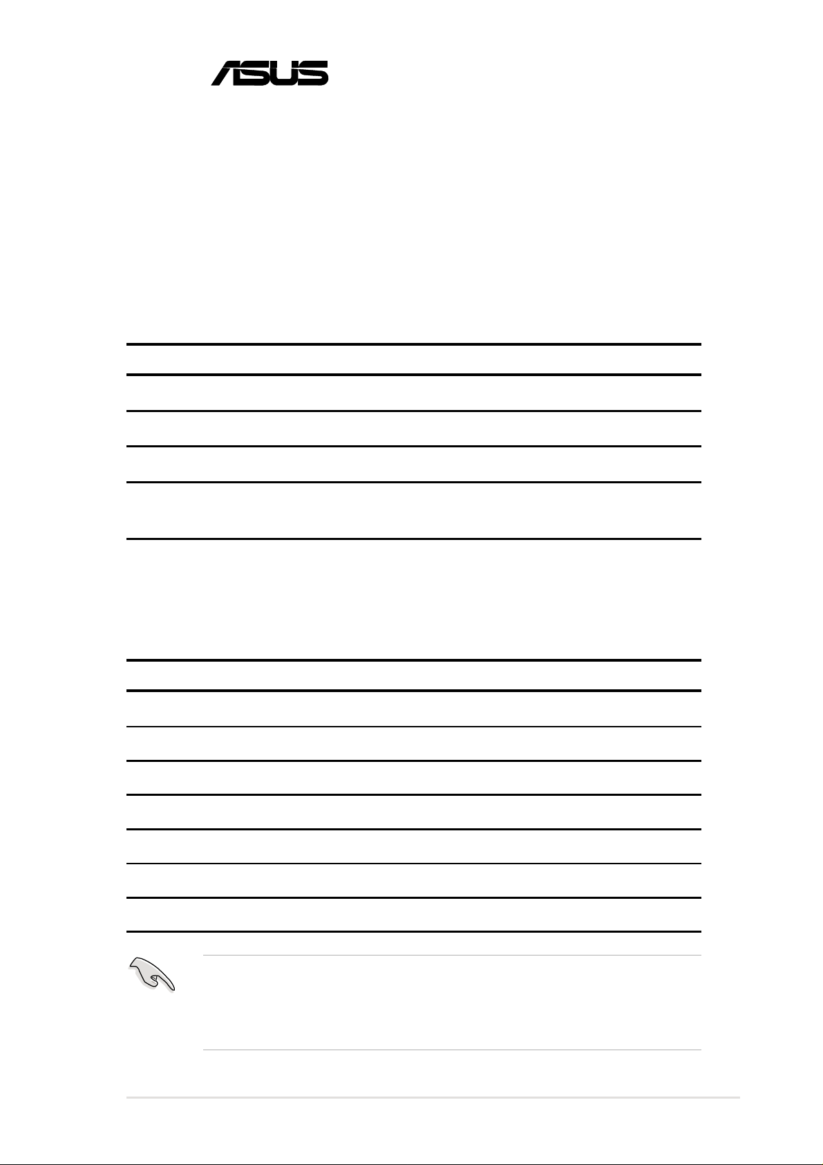
2.6.4 AGP 4x slot (page 18)
A7V333
®
A7V333 Accelerated Graphics Port (AGP)
CAUTION! To avoid damaging your AGP/AGP 4x graphics card, the
computer power supply should be unplugged before inserting the graphics
card into the slot.
Keyed for 1.5v
The description for the BIOS DRAM Burst Length field is updated to its correct
form:
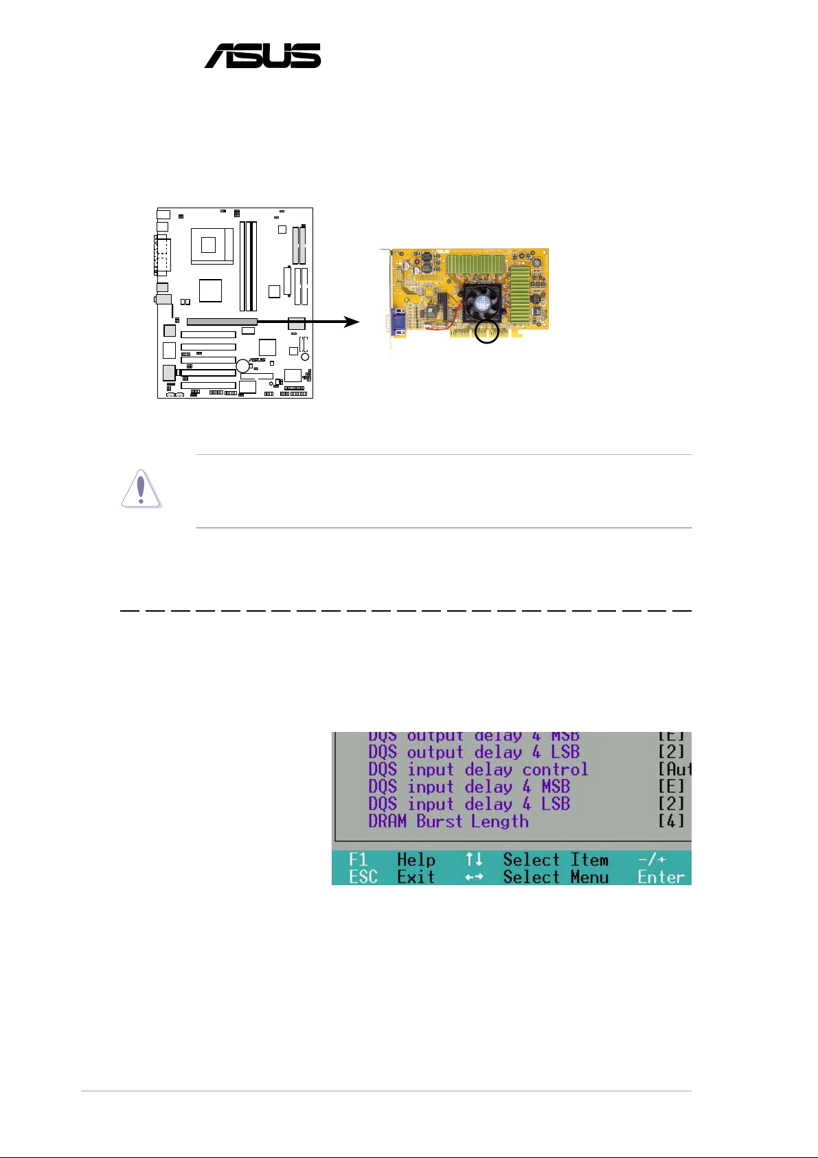
4.4.1 Chip Configuration (page 65-67)
DRAM Burst Length [4]
This item determines the
maximum number of
column locations for a given
DRAM READ or WRITE
command. The default
setting is [4]. The other
setting is [AUTO]. Setting [AUTO] will depend on the DRAM to set the burst
length. Setting [4] always sets the burst length to 4. Configuration options:
[Disabled] [Enabled] [Auto]
2
ASUS A7V333 Technical Updates
Page 3

®
A7V333 Updates
The description for clearing the RTC RAM memory is updated:
16)Clear RTC RAM (CLR_RTC) (page 28)
This jumper allows you to clear the Real Time Clock (RTC) RAM in CMOS.
Y ou can clear the CMOS memory of date, time, and system setup parameters
by erasing the CMOS RTC RAM data. The RAM data in CMOS is powered
by the onboard button cell battery.
To erase the RTC RAM:
1. Turn OFF the computer and unplug the power cord.
2. Remove the battery.
3. Short the jumper by replacing a jumper cap on the two pins.
4. Removing the cap after 3 seconds.
5. Re-install the battery.
6. Plug the power cord and turn ON the computer.
7. Hold down the <Del> key during the boot process and enter BIOS
setup to re-enter data.
A7V333
A7V333 Clear RTC RAM
®
CLR_RTC
ASUS A7V333 Technical Updates
3
Page 4

®
A7V333 Updates
The reference on page 31 to the connector configuration for the C-media 6Channel audio set-up is completed by the section below , which was left out
of the manual:
5. Connector Configuration
The chart below displays the configurations for the line connectors on the
yellow MIDI/Game/Audio connector port located on the back panel. The
three female connectors are available for use in the 6-Channel audio
system.
Connector Settings and Functions
Headphone/ 4-Speaker 6-Speaker
2-Speaker
In
Light Blue Line In
Rear Spkr Out
Rear Speaker Out
Lime Line Out/ Line Out/ Line Out/
Front SpkrOut Front Spkr Out Front Spkr Out
Pink Mic In Mic In Center Speaker Out,
Sub-woofer
Out
Mic
The heading on page 87 for the FastTrak133 BIOS is corrected below:
5.4.2 Enter FastTrak133 BIOS and FastBuild Utility
1. Boot-up your computer once more. If this is the first time you have booted
with two hard disks correctly installed, then MBFastT rak133™ “Lite” BIOS
scans the IDE drives and displays this screen:
For updated processor settings, visit the ASUS web site: www.asus.com.tw
SPECIFICATIONS AND INFORMATION CONTAINED IN THIS MANUAL ARE FURNISHEDFOR INFORMATIONAL USE ONLY, AND ARE SUBJECT TO CHANGE AT ANY TIME WITHOUT NOTICE, AND SHOULD
NOT BE CONSTRUED AS A COMMITMENT BY ASUSTeK COMPUTER INC. ASUS ASSUMES NO RESPONSIBILITY OR LIABILITY FOR ANY ERRORS OR INACCURACIES THAT MAY APPEAR IN THIS MANUAL,
INCLUDING THE PRODUCTS AND SOFTWARE DESCRIBED IN IT.
Copyright © 2002 ASUSTeK COMPUTER INC. All Rights Reserved.
4
ASUS A7V333 Technical Updates
 Loading...