

ASUS A7V266-M User Manual

®
A7V266-M
User Guide
Motherboard

Checklist
Product Name: A7V266-M
Manual Revision: 1.00 E921
Release Date: December 2001
Copyright © 2001 ASUSTeK COMPUTER INC. All Rights Reserved.
No part of this manual, including the products and software described in it, may be reproduced,
transmitted, transcribed, stored in a retrieval system, or translated into any language in any
form or by any means, except documentation kept by the purchaser for backup purposes,
without the express written permission of ASUSTeK COMPUTER INC. (“ASUS”).
Product warranty or service will not be extended if: (1) the product is repaired, modified or
altered, unless such repair, modification of alteration is authorized in writing by ASUS; or (2)
the serial number of the product is defaced or missing.
Products and corporate names appearing in this manual may or may not be registered
trademarks or copyrights of their respective companies, and are used only for identification
or explanation and to the owners’ benefit, without intent to infringe.
• Intel and Pentium are registered trademarks of Intel Corporation.
• VIA is a registered trademark of VIA Technologies, Inc.
• 3Com is a registered trademark of 3Com Corporation.
• C-Media is a registered trademark of C-Media Electronics Inc.
• Windows and MS-DOS are registered trademarks of Microsoft Corporation.
• Adobe and Acrobat are registered trademarks of Adobe Systems Incorporated.
• Trend and ChipAwayVirus are trademarks of Trend Micro, Inc.
• Symbios is a registered trademark of Symbios Logic Corporation.
• nVidia is a registered trademark of NVIDIA Corporation.
The product name and revision number are both printed on the product itself. Manual revisions
are released for each product design represented by the digit before and after the period of
the manual revision number. Manual updates are represented by the third digit in the manual
revision number.
For previous or updated manuals, BIOS, drivers, or product release information, contact
ASUS at: http://www.asus.com or through any of the means indicated on the following page.
ASUS PROVIDES THIS MANUAL “AS IS” WITHOUT WARRANTY OF ANY KIND, EITHER EXPRESS
OR IMPLIED, INCLUDING BUT NOT LIMITED TO THE IMPLIED WARRANTIES OR CONDITIONS OF
MERCHANTABILITY OR FITNESS FOR A PARTICULAR PURPOSE. IN NO EVENT SHALL ASUS, ITS
DIRECTORS, OFFICERS, EMPLOYEES OR AGENTS BE LIABLE FOR ANY INDIRECT, SPECIAL,
INCIDENTAL, OR CONSEQUENTIAL DAMAGES (INCLUDING DAMAGES FOR LOSS OF PROFITS,
LOSS OF BUSINESS, LOSS OF USE OR DATA, INTERRUPTION OF BUSINESS AND THE LIKE),
EVEN IF ASUS HAS BEEN ADVISED OF THE POSSIBILITY OF SUCH DAMAGES ARISING FROM
ANY DEFECT OR ERROR IN THIS MANUAL OR PRODUCT.
SPECIFICATIONS AND INFORMATION CONTAINED IN THIS MANUAL ARE FURNISHED FOR
INFORMATIONAL USE ONLY, AND ARE SUBJECT TO CHANGE AT ANY TIME WITHOUT NOTICE,
AND SHOULD NOT BE CONSTRUED AS A COMMITMENT BY ASUS. ASUS ASSUMES NO
RESPONSIBILITY OR LIABILITY FOR ANY ERRORS OR INACCURACIES THAT MAY APPEAR IN
THIS MANUAL, INCLUDING THE PRODUCTS AND SOFTWARE DESCRIBED IN IT.
ii
About this guide
This user manual contains complete information for installing the ASUS
A7V266-M motherboard.
How this guide is organized
• Chapter 1: Product introduction. A summary of product features and
special attributes of new technologies.
• Chapter 2: Hardware information. A list of hardware setup procedures
and descriptions of all jumpers and connectors on the motherboard.
• Chapter 3: Powering up. Describes the power up sequence with
information on BIOS beep codes.
• Chapter 4: BIOS setup. How to change system settings using onboard
BIOS firmware. Detailed descriptions of the BIOS parameters are supplied.
• Chapter 5: Software support. A summary of contents on the
motherboard support CD ROM.
• Appendix and Glossary . Optional components and technical definitions.
• Index
Conventions used in this guide
Features
T o make sure that you perform set-up tasks properly , take note of the following
symbols used throughout this manual.
WARNING! Information to prevent injury to yourself.
CAUTION! Information to prevent damage to the components.
IMPORTANT! Information that you MUST follow to complete a task.
NOTE! T ips and helpful information.
iii

Contents
Safeguards
About this guide .............................................................................. iii
Safety information ...........................................................................vi
FCC/CDC statements .................................................................... vii
ASUS contact information ............................................................. viii
Chapter 1: Product introduction ............................................. 1
Welcome!........................................................................................ 1
1.1 Package contents .................................................................. 1
1.2 Core Specifications ................................................................ 2
1.3 Special Features .................................................................... 3
1.4 Motherboard Components...................................................... 4
1.4.1 Component Locations................................................ 5
Chapter 2: Hardware information ............................................ 7
2.1 Motherboard installation ......................................................... 7
2.1.1 Placement direction ................................................... 7
2.1.2 Screw holes............................................................... 7
2.2 Motherboard layout ................................................................ 8
2.2.1 Layout contents ......................................................... 9
2.3 Before you proceed...............................................................10
2.4 Central Processing Unit (CPU)..............................................11
2.4.1 Overview .................................................................. 11
2.4.2 Installing the CPU .................................................... 12
2.5 System memory ....................................................................13
2.5.1 Overview ..................................................................13
2.5.2 Memory configurations ............................................ 14
2.5.3 Installing a DIMM ..................................................... 14
2.6 Expansion slots.....................................................................15
2.6.1 Installing an expansion card..................................... 15
2.6.2 Configuring an expansion card ................................ 16
2.6.3 PCI slots ...................................................................17
2.6.4 AGP slot ...................................................................18
2.7 Switches and jumpers ...........................................................19
iv
2.8 Connectors ...........................................................................25

Contents
Chapter 3: Powering up ......................................................... 39
3.1 Starting up for the first time................................................... 39
3.2 Powering off the computer.................................................... 40
Chapter 4: BIOS setup ........................................................... 41
4.1 Managing and updating your BIOS....................................... 41
4.1.1 Using the computer system for the first time ............ 41
4.1.2 Updating BIOS procedures ...................................... 43
4.2 BIOS Setup program.............................................................45
4.2.1 BIOS menu bar.........................................................46
4.2.2 Legend bar ...............................................................46
4.3 Main Menu ............................................................................48
4.3.1 Primary and Secondary Master/Slave...................... 49
4.3.2 Keyboard Features .................................................. 53
4.4 Advanced Menu ....................................................................55
4.4.1 Chip Configuration ................................................... 58
4.4.2 I/O Device Configuration.......................................... 61
4.4.3 PCI Configuration .................................................... 63
4.5 Power Menu..........................................................................65
4.5.1 Power Up Control .................................................... 67
4.5.2 Hardware Monitor .................................................... 69
4.6 Boot Menu ............................................................................70
4.7 Exit Menu..............................................................................72
Chapter 5: Software support ................................................. 75
5.1 Install an operating system................................................... 75
5.2 Support CD information.........................................................75
5.3 A7V266-M Motherboard Support CD.................................... 76
5.4 ASUS PC Probe....................................................................79
5.5 ASUS Live Update ................................................................84
5.6 3Deep Color Tuner................................................................85
Glossary .................................................................................. 87
Index ........................................................................................ 91
v

Safet y information
Electrical safety
• To prevent electrical shock hazard, disconnect the power cable from the
electrical outlet before relocating the system.
• When adding or removing devices to or from the system, ensure that the
power cables for the devices are unplugged before the signal cables are
connected. Disconnect all power cables from the existing system before
you add a device.
• Before connecting or removing signal cables from the motherboard, ensure
that all power cables are unplugged.
• Seek professional assistance before using an adpater or extension cord.
These devices could interrupt the grounding circuit.
• Make sure that your power supply is set to the voltage available in your
area.
• If the power supply is broken, contact a qualified service technician or your
retailer.
Operational safety
• Before installing the motherboard and adding new devices, carefully read
all the manuals that came with the package.
• Before use ensure all cables are correctly connected and the power cables
are not damaged. If you detect any damage, contact the dealer immediately .
• To avoid short circuits, keep paper clips, screws, and staples away from
connectors, slots, sockets and circuitry.
• Avoid dust, humidity, and temperature extremes. Do not place the product
in any area where it may become wet.
• Mount the motherboard inside a standard PC enclosure.
• If you encounter technical problems with the product, contact a qualified
service technician or the dealer.
vi

FCC/CDC statements
Federal Communications Commission Statement
This device complies with FCC Rules Part 15. Operation is subject to the
following two conditions:
• This device may not cause harmful interference, and
• This device must accept any interference received including interference
that may cause undesired operation.
This equipment has been tested and found to comply with the limits for a
Class B digital device, pursuant to Part 15 of the FCC Rules. These limits
are designed to provide reasonable protection against harmful interference
in a residential installation. This equipment generates, uses and can radiate
radio frequency energy and, if not installed and used in accordance with
manufacturer’s instructions, may cause harmful interference to radio
communications. However, there is no guarantee that interference will not
occur in a particular installation. If this equipment does cause harmful
interference to radio or television reception, which can be determined by
turning the equipment off and on, the user is encouraged to try to correct the
interference by one or more of the following measures:
• Reorient or relocate the receiving antenna.
• Increase the separation between the equipment and receiver.
• Connect the equipment to an outlet on a circuit different from that to
which the receiver is connected.
• Consult the dealer or an experienced radio/TV technician for help.
The use of shielded cables for connection of the monitor to the
graphics card is required to assure compliance with FCC regulations.
Changes or modifications to this unit not expressly approved by the
party responsible for compliance could void the user’s authority to
operate this equipment.
Canadian Department of Communications Statement
This digital apparatus does not exceed the Class B limits for radio noise
emissions from digital apparatus set out in the Radio Interference
Regulations of the Canadian Department of Communications.
This class B digital apparatus complies with Canadian ICES-003.
vii

ASUS contact information
ASUSTeK COMPUTER INC. (Asia-Pacific)
Marketing
Address: 150 Li-Te Road, Peitou, Taipei, Taiwan 112
Telephone: +886-2-2894-3447
Fax: +886-2-2894-3449
Email: info@asus.com.tw
Technical Support
Tel (English): +886-2-2890-7123
Tel (Chinese): +886-2-2890-7113
Fax: +886-2-2890-7698
Email: tsd@asus.com.tw
Newsgroup: cscnews.asus.com.tw
WWW: www.asus.com.tw
FTP: ftp.asus.com.tw/pub/ASUS
ASUS COMPUTER INTERNATIONAL (America)
Marketing
Address: 6737 Mowry Avenue, Mowry Business Center, Building 2
Newark, CA 94560, USA
Fax: +1-510-608-4555
Email: info-usa@asus.com.tw
Technical Support
Fax: +1-510-608-4555
BBS: +1-510-739-3774
Email: tsd@asus.com
WWW: www.asus.com
FTP: ftp.asus.com/pub/ASUS
ASUS COMPUTER GmbH (Europe)
Marketing
Address: Harkortstr. 25, 40880 Ratingen, BRD, Germany
Fax: +49-2102-442066
Email: sales@asuscom.de (for marketing requests only)
Technical Support
Hotline: MB/Others: +49-2102-9599-0
Notebook: +49-2102-9599-10
Fax: +49-2102-9599-11
Support (Email): www.asuscom.de/de/support (for online support)
WWW: www.asuscom.de
FTP: ftp.asuscom.de/pub/ASUSCOM
viii
Chapter 1
Product introduction

ASUS P4S333-M motherboard

Welcome!
Thank you for buying the ASUS® A7V266-M motherboard!
The A7V266-M is powered by AMD
processors and supplies advanced features to ensure long-lasting,
superlative performance. The ASUS
choice for home PCs and workstations.
~ CPU Thermal Protection
~ Up to 3GB of system memory of the latest DDR RAM
~ High-resolution graphics via an AGP 4X slot
~ Digital Audio Interface for 3D sound
™
~ Realtek
~ UltraDMA 100 data rates
The A7V266-M is the perfect vehicle to get ahead in the world of power
computing!
LAN networking
®
Athlon™, Athlon™ XP and Duron
®
A7V266-M motherboard is the prime
™
1.1 Package contents
Check your A7V266-M package for the following items.
ASUS A7V266-M motherboard (MicroATX form factor: 9.6 in x 9.6 in)
ASUS A7V266-M support CD
ASUS 2-port USB module
80-conductor ribbon cable for UltraDMA/33/66/100 IDE drives
40-conductor IDE cable
Ribbon cable for a 3.5-inch floppy drive
Bag of extra jumper caps
User Guide
If any of the above items is damaged or missing, contact your retailer.
ASUS A7V266-M motherboard user guide
1

1.2
Core Specifications
The A7V266-M motherboard is designed and assembled according to the
highest standards. This ASUS motherboard represents the latest advances
and offers users the finest componentry available today...
®
AMD
Athlon™/ Athlon™ XP and Duron™ Socket A (462) Processor
North Bridge Chipset: the VIA
®
KT266A supports AGP 4X/2X mode,
133/100MHz Front Side Bus, and the fastest 266/200MHz memory bus.
®
South Bridge Chipset: the VIA
VT8233 integrated peripheral controller
supports UltraDMA/100/66/33 for burst mode data transfer rates of up to
100MB/sec, and USB controller with three root hubs for six USB ports.
PC2100 / PC1600 DDR Support: Equipped with three Double Data Rate
Dual Inline Memory Module (DDR DIMM) sockets to support up to 3GB of
DDR DRAM, the newest memory standard with the highest bandwidth
and lowest latency currently available. This new memory technology
increases performance by executing two actions per clock cycle, resulting
in data transfer rates of up to 2.1 GB/s for 133MHz DDR SDRAM and
1.6GB/s for 100MHz DDR SDRAM.
UltraDMA/100 Support: Comes with an onboard PCI Bus Master IDE
controller with two connectors that support four IDE devices on two
channels. Supports UltraDMA/100/66/33, PIO Modes 3 & 4, Bus Master
IDE DMA Mode 2, and Enhanced IDE devices, such as DVD-ROM, CDROM, CD-R/RW, LS-120, and Tape Backup drives.
Multi-I/O Chipset: Offers complete support for a variety of I/O functions.
Provides two high-speed UART compatible serial ports and one parallel
port with EPP and ECP capabilities. UART2 can also be directed from
COM2 to the Infrared Module for wireless connections. The Super I/O
controller supports a floppy disk drive, PS/2 keyboard, and PS/2 mouse.
Smart BIOS: 2Mb firmware enables Vcore and CPU/DDR SDRAM frequency
adjustments, boot block write protection, and HD/SCSI/MO/ZIP/CD/Floppy
boot selection.
Expansion: One AGP 4X, four USB ports, two PCI slots, Infrared port
Connections: Parallel Port, PS/2 mouse Port, PS/2 keyboard,
RJ-45, Microphone, Line In Jack, Line Out Jack, Game/MIDI Connector ,
Standard A TX power.
2
Chapter 1: Product introduction

1.3 Special Features
Easy Overclocking
™
• Quickly adjust CPU frequency multiples with BIOS in JumperFree
• Adjustable FSB/MEM/PCI frequency ratio
• Stepless Frequency Selection (SFS) for fine-tuning system bus frequency
from at 1MHz increments
• Optimal system performance available with BIOS built-in Turbo Mode
• Adjustable Vcore Voltage and VIO
• Alternatively, easy-to-use DIP switches permit manual adjustment of the
processor external/internal frequency settings.
Mode
Thermal Protection: With AMD
®
Athlon XP™ installed, the motherboard offers
automatic CPU Overheating Protection to prolong the life of the entire
system. If the CPU temperature exceeds the set criteria, the PC shuts
down automatically.
Realtek LAN: Full networking built-in with the RTL8100 controller with driver
support and onboard RJ-45 input jack. (Optional)
T emperature, Fan and V oltage Monitoring: CPU temperature is monitored
by the ASUS ASIC through the CPU’s internal thermal diode to prevent
overheating and damage. The CPU and system fans can be monitored
for RPM and failure. System voltage levels are monitored to ensure
stable voltage to critical motherboard components.
ACPI Ready: Advanced Configuration Power Interface (ACPI) provides more
Energy Saving Features for operating systems that support OS Direct
Power Management (OSPM).
Concurrent PCI: Concurrent PCI allows multiple PCI transfers from PCI
master busses to the memory and processor.
Auto Fan Off: The system fans powers off automatically even in sleep mode.
Dual Function Power Button: Push the power button for less than 4 seconds
when the system is operating places the system into sleep or soft-off
modes, depending on the BIOS or OS setting. If the power button is
pressed for more than 4 seconds, the system enters the soft-off mode
regardless of the BIOS setting.
ASUS A7V266-M motherboard user guide
3

1.4
Motherboard Components
Before installing the A7V266-M motherboard, take time to familiarize yourself
with its physical configuration: understanding the motherboard makes
upgrading easy . Sufficient knowledge of specifications will prevent accidental
damage to the board.
Location
Processor Support Socket A for AMD
Feature Setting DIP Switches ......................................... 4
®
Chipsets VIA
Main Memory Maximum 3GB support
Expansion Slots 2 PCI Slots .................................................................... 18
System I/O 1 Floppy Disk Drive Connector .......................................8
Hardware Monitoring System Voltage Monitor (Integrated in ASUS ASIC) ....... 7
Special Feature Onboard LED .................................................................. 6
Audio Features (on audio models only)
KT266A North Bridge .............................................. 2
®
VT8233 South Bridge ............................................ 14
VIA
Multi-I/O controller ......................................................... 11
2Mbit Programmable Flash EEPROM ..........................10
3 DDR DIMM Sockets ..................................................... 3
1 Accelerated Graphics Port (AGP) 4X Slot..................20
2 IDE Connectors (UltraDMA/100 Support) .................... 9
1 Panel Connector ........................................................12
1 Infrared Connector ..................................................... 13
USB Headers (Ports 2/3) ..............................................15
1 Parallel Port................................................................23
2 Serial Ports (COM1/COM2) .......................................28
USB Connectors (Port 0 & Port 1) ............................... 29
1 PS/2 Mouse Connector .................................(green) 21
1 PS/2 Keyboard Connector .......................... (purple) 30
Audio CODEC Controller Chipset ................................. 16
1 ASUS Front Audio Panel Connector ..........................17
®
Athlon™ and Duron™ Processors.......1
1 Game/MIDI Port ........................................................ 24
1 Line Out Connector ......................................... (lime) 27
1 Line In Connector ................................... (light blue) 26
1 Microphone Connector .................................... (pink) 25
Power ATX Power Supply Connector ......................................... 5
Form Factor MicroATX
4
Chapter 1: Product introduction
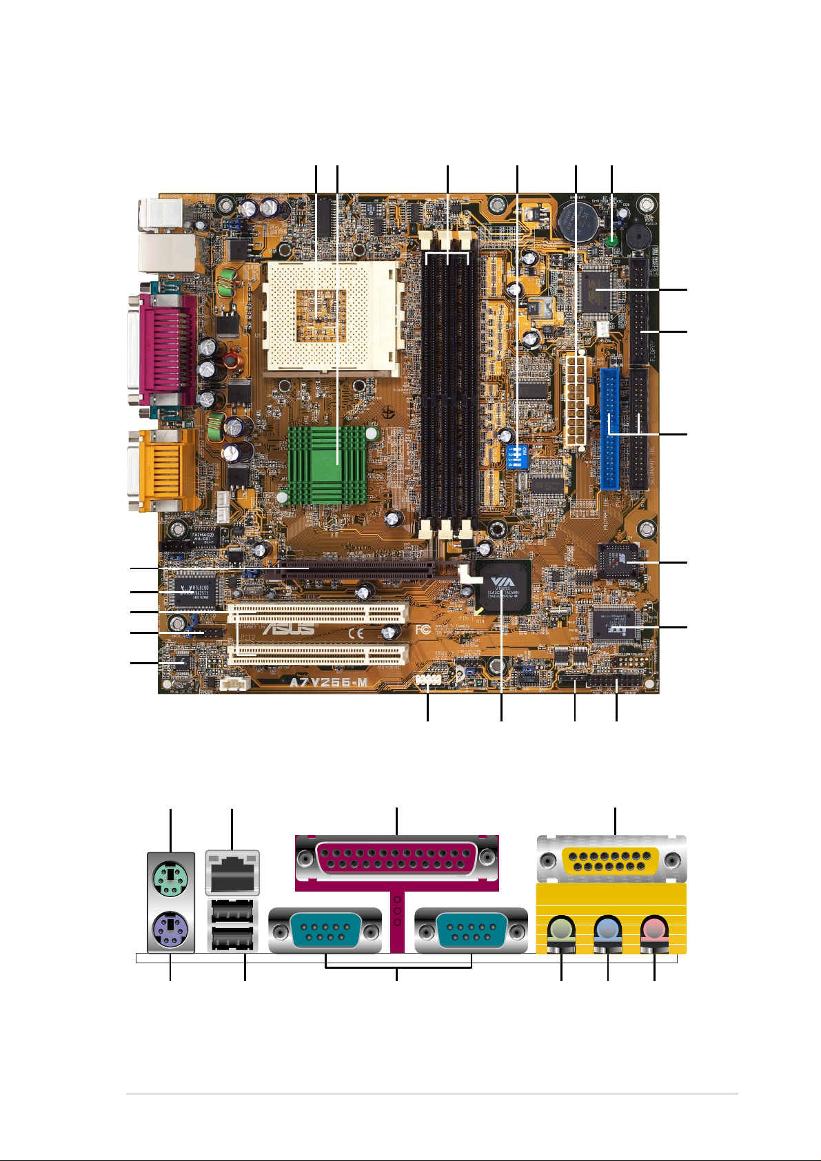
1.4.1 Component Locations
1162 4 5 6
3
7
8
9
20
19
18
17
15
21 22 23 24
14
13
12
10
11
ASUS A7V266-M motherboard user guide
25262730 29 28
5

Chapter 2
Hardware information

ASUS P4S333-M motherboard
2.1 Motherboard installation
The A7V266-M uses the micro-ATX form factor that measures 9.6 inches x
9.6 inches, a standard fit for most chassis.
WARNING! Unplug the power cord before installing the motherboard.
Failure to do so may cause you physical injury and damage motherboard
components.
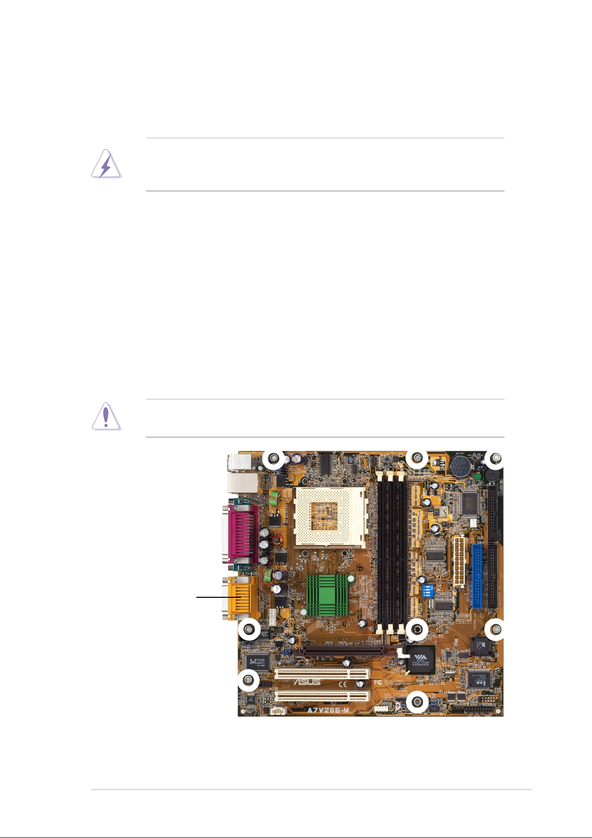
2.1.1 Placement direction
When installing the motherboard, take care to orient the chassis correctly:
The edge with external ports goes to the rear part of the chassis. Refer to the
image below. It may be more convenient to install major cables, the CPU
and modular components before fixing the motherboard inside the case frame.
2.1.2 Screw holes
Place eight screws into the holes indicated by circles to secure the
motherboard to the chassis.
CAUTION! Do not overtighten the screws! Doing so may damage the
motherboard.
Place this side towards
the rear of the chassis
ASUS A7V266-M motherboard user guide
7
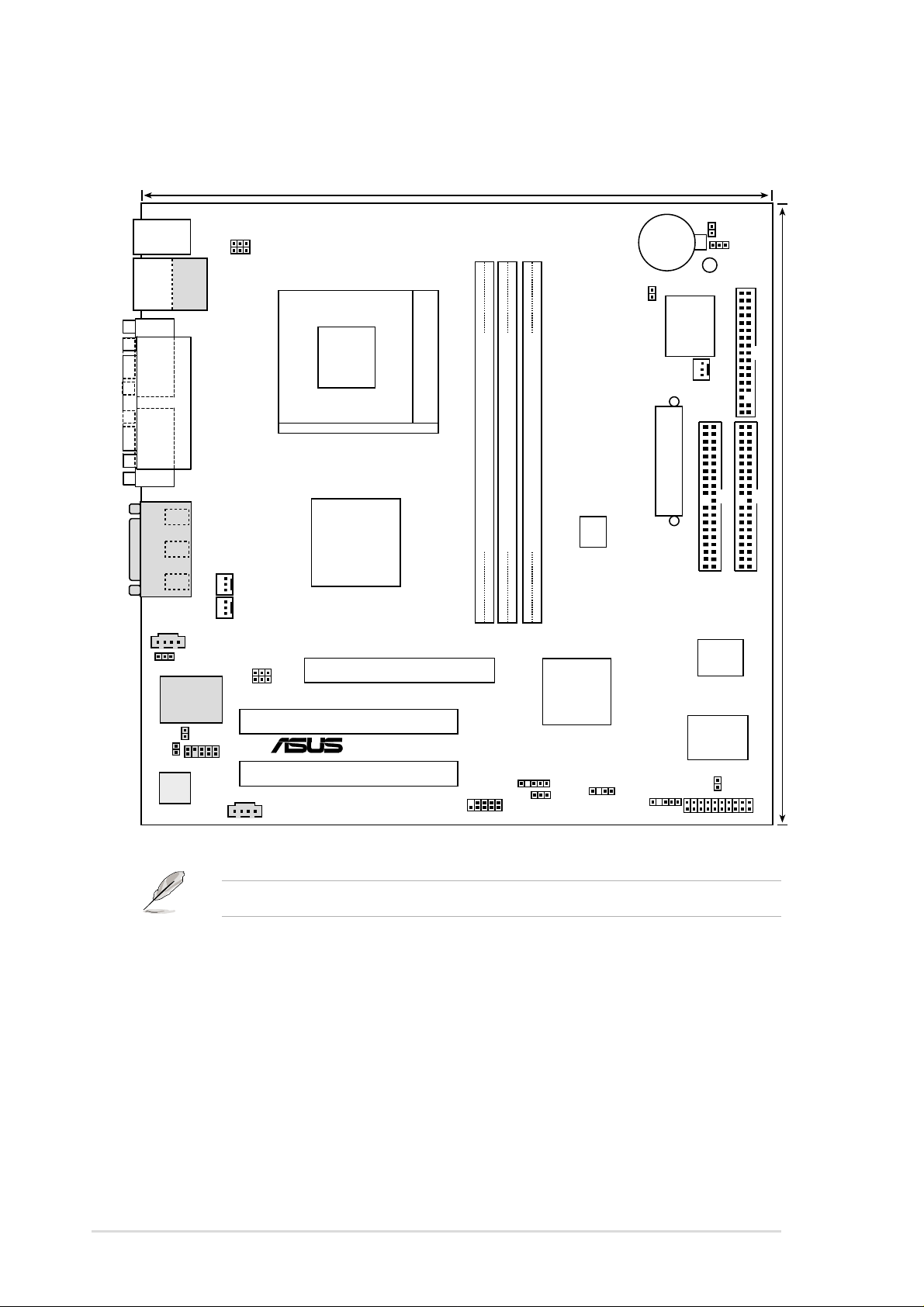
2.2 Motherboard layout
24.4cm (9.60in)
PS/2KBMS
T: Mouse
B: Keyboard
Bottom:
Top:
USB1
RJ-45
USB2
COM1
COM2
Line
Out
Line
In
Mic
In
GAME_AUDIO
LAN_EN
Realtek
RTL8100
BACK_RT
Audio
Codec
PARALLEL PORT
CD1
BACK_LT
AUX
USB01_PWR
KBWR
CPU_FAN
PWR_FAN
IPANEL
Chipset
JP1
JP2
A7V266-M
VIA
KT266A
Accelerated Graphics Port
(AGP+1.5V)
PCI1
®
PCI2
Socket 462
DDR DIMM1 (64/72 bit, 184-pin module)
0 1
2 3
USB2_3
CLR_RTC
CR2032 3V
Lithium Cell
CMOS Power
LED1
JTPWR
ASUS
ASIC
with Hardware
Monitor
CHR_FAN
ATX Power Connector
DDR DIMM2 (64/72 bit, 184-pin module)
DDR DIMM3 (64/72 bit, 184-pin module)
SYSCLK
4 5
PRIMARY IDE
2Mbit
Firmware
VIA
VT8233
Chipset
Super
I/O
SMB_CON
USB23_PWR
CHASSIS
IR
PANEL
Hub
JEN
IDELED
FLOPPY
24.4cm (9.6in)
SECONDARY IDE
Optional components are grayed in the above motherboard layout.
8
Chapter 2: Hardware information

2.2.1 Layout contents
CPU, Memory and Expansion Slots
1) Socket 462 p. 11 CPU Support
2) DIMM 1/2/3 p. 13 System Memory Support
3) PCI 1/2 p. 15 32-bit PCI Bus Expansion Slots
4) AGP 4x p. 18 Accelerated Graphics Slot
Motherboard Settings (Switches and Jumpers)
1) JEN p. 19 JumperFree Mode Setting (Disable / Enable)
2) SYSCLK p. 20 CPU External Frequency Selection (Switches 1–4)
USB01_, USB23_PWR
3)
4) KBWK p. 22 Keyboard Wake Up (Enable / Disable)
5) LAN_EN p. 23 LAN Enable (Enable / Disable)
6) CLR_RTC p. 24 Clear RTC RAM (2 pin)
Connectors
1) PS2KBMS p. 25 PS/2 Mouse Port (6 pin female)
2) PS2KBMS p. 25 PS/2 Keyboard Port (6 pin female)
3) USB p. 26 Universal Serial Bus Ports 1 & 2 ( T w o 4 pin female)
4) PRINTER p. 26 Parallel Port (25 pin female)
5) COM1/COM2 p. 26 Serial Ports (9 pin /10-1 pin male)
6) GAME_AUDIO p. 27 Game/MIDI Port (15 pin female) (optional)
7) AUDIO p. 27 Audio Connectors (Three 1/8” AUDIO) (optional)
8) IDELED p. 28IDE Activity LED (2 pin)
9) FLOPPY p. 28 Floppy Disk Drive Connector (34 pin)
10) PRIMARY / SEC. IDE p. 29 IDE Connectors (Two 40-1 pin)
11) CPU/PWR/CHA_FAN p. 30
12) IR_CON p. 31Standard Infrared Module Connector (10-1 pin)
13) ATXPWR p. 32ATX Power Supply Connector (20 pin)
14) SMB p. 32 SMBus Connector (5-1 pin)
15) CD / AUX / MODEM p. 33 Internal Audio Connectors
16) USB2_3 p. 34 USB Headers (10-1 pin)
17) JTPWR p. 34 Power Supply Thermal Sensor Connector (2 pin)
18) CHASSIS p. 35 Chassis Intrusion Lead (2 pin)
19) BACK_LT / BACK_RT p. 35 Power Supply Thermal Sensor (2 pin)
20) IPANEL p. 36 ASUS Front Panel Audio Connector (10-1 pin)
PLED (
21)
22) KEYLOCK
23) SPEAKER (PANEL) p. 37 System Warning Speaker Lead (4 pin)
24) MLED (PANEL) p. 37 System Message LED Lead (2 pin)
25) SMI (PANEL) p. 37 System Management Interrupt Lead (2 pin)
26) PWR (PANEL) p. 37 ATX / Soft-Off Switch Lead (2 pin)
27) RESET (PANEL) p. 37 Reset Switch Lead (2 pin)
PANEL
)
(
PANEL)p. 37 System Keyboard Lock Switch Lead (2 pin)
p. 21 USB Device Wake-up (+5V / +5VSB)
CPU, Power, and Chassis Fan Connectors (Three 3 pin)
(Three 4-1 pin) (optional)
p. 37 System Power LED Lead (3 pin)
ASUS A7V266-M motherboard user guide
9
2.3 Before you proceed
Take note of the following precautions before you install motherboard
components or change any motherboard settings.
CAUTION!
1. Unplug the power cord from the wall socket before touching any
component.
2. Use a grounded wrist strap or touch a safely grounded object or to a
metal object, such as the power supply case, before handling
components to avoid damaging them due to static electricity.
3. Hold components by the edges and do not to touch the ICs on them.
4. Whenever you uninstall any component, place it on a grounded
antistatic pad or in the bag that came with the component.
5. Before you install or remove any component, ensure that the
A TX power supply is switched off or the power cord is detached
from the power supply . Failure to do so may cause severe damage
to the motherboard, peripherals, and/or components.
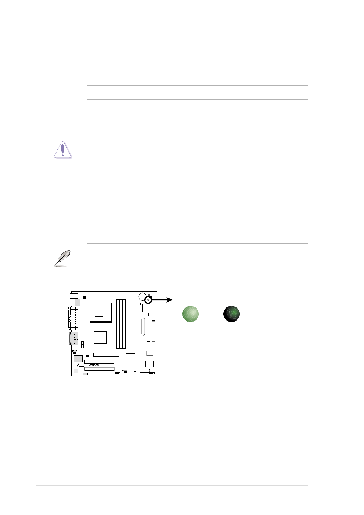
NOTE! When lit, the onboard LED indicates that the system is ON, in
sleep mode or in soft-off mode, not powered OFF. See the illustration
below.
®
A7V266-M
A7V266-M Onboard LED
ON
Standby
Power
OFF
Powered
Off
10
Chapter 2: Hardware information
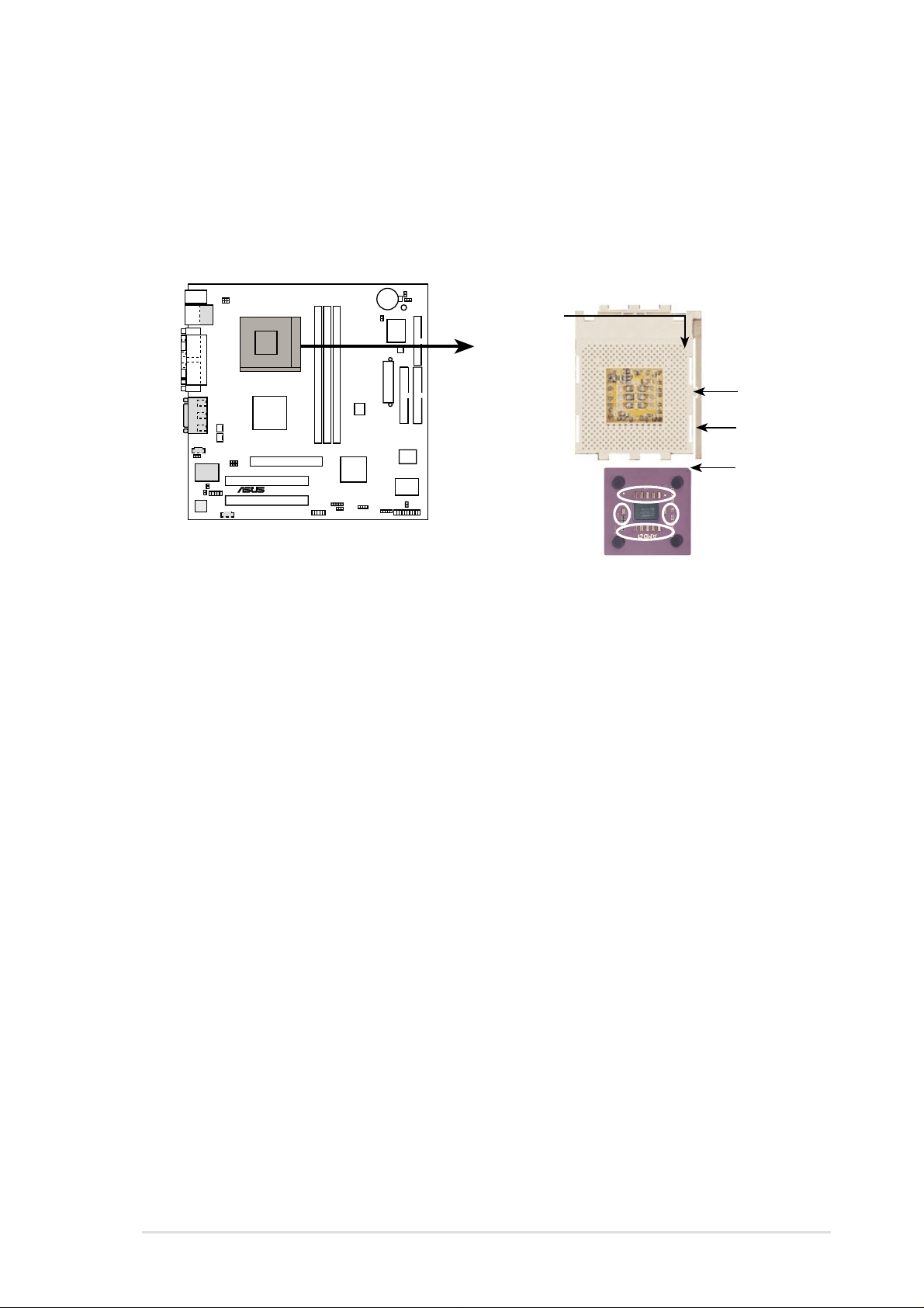
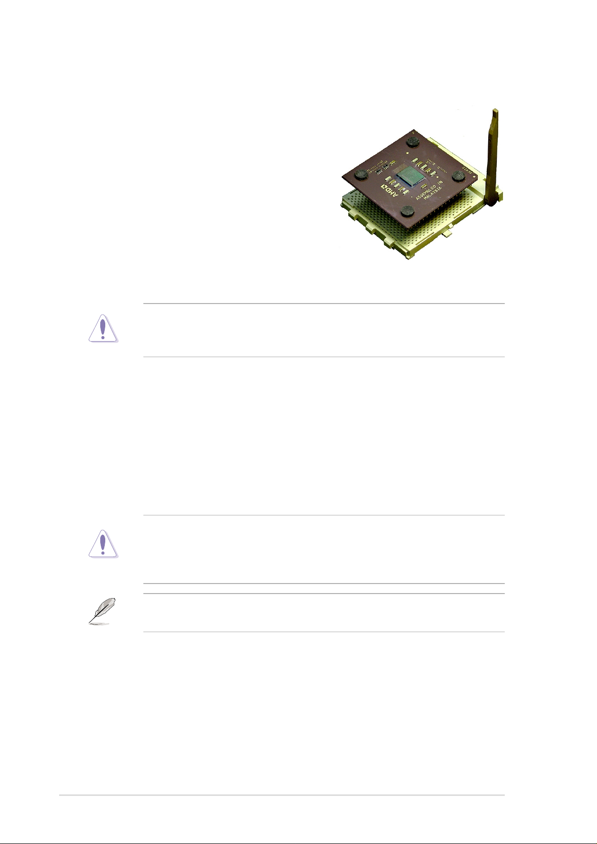
2.4 Central Processing Unit (CPU)
2.4.1 Overview
The motherboard provides a Socket A (462) for CPU installation. A fan and
heatsink should be attached to the CPU to prevent overheating.
CPU NOTCH
TO INNER
CORNER
LOCK
LEVER
®
A7V266-M
A7V266-M Socket A
AMD™ CPU
CPU NOTCH
ASUS A7V266-M motherboard user guide
11
2.4.2 Installing the CPU
Follow these steps to install a CPU:
1. Locate the Socket 462 and open it by
pulling the lever gently sideways away
from the socket. Then lift the lever
upwards. The socket lever must be fully
opened (90 to 100 degrees).
2. Insert the CPU with the correct
orientation. The notched corner of the
CPU must be oriented toward the inner
corner of the socket base nearest to the
lever hinge.
CAUTION! The CPU should drop easily into place. Do not force the
CPU into the socket to avoid bending the pins. If the CPU does not fit,
check its alignment and look for bent pins.
4. Once completely inserted, press the CPU firmly and close the socket
lever until it snaps shut.
5. Place the CPU fan and heatsink on the CPU. The heatsink should entirely
cover the CPU. Carefully attach the heatsink locking brace to the plastic
clips on the socket base. With the added weight of the CPU fan and
heatsink locking brace, no extra force is required to keep the CPU in
place
CAUTION! Take care not to scrape the motherboard surface when
mounting a clamp-style processor fan, or else damage may occur . When
mounting a heatsink onto your CPU, make sure that exposed CPU
capacitors do not touch the heatsink, or damage may occur!
NOTE! Do not neglect to set the correct Bus Frequency and leave the
CPU Multiple setting at default to avoid start-up problems.
12
Chapter 2: Hardware information
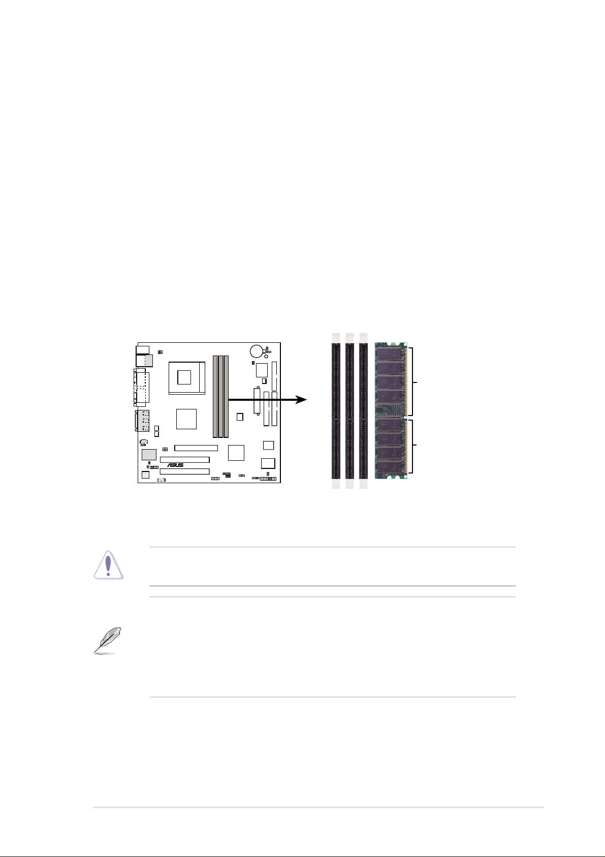
2.5 System memor y
2.5.1 Overview
This motherboard uses only Double Data Rate (DDR) Synchronous Dynamic
Random Access Memory (SDRAM) Dual Inline Memory Modules (DIMMs).
These sockets support up to 3GB system memory using non-ECC PC200/
266 DIMMs.
Each DIMM socket/module is two-sided: each side defines one “row” of
memory. DIMMs come in combinations of single or double-sided types
ranging through 64MB, 128MB, 256MB, 512MB and 1GB to form a total
memory size of 64MB to 3GB.
~ Three (3) sockets are available for both 266MHz-PC2100 or 200MHzPC1600 DDR DIMMs to form a memory size of 64MB to 3GB.
104 Pins
80 Pins
®
A7V266-M
A7V266-M 184-Pin DDR DIMM Sockets
CAUTION! DIMMs are keyed to fit into notches with only one direction.
DO NOT force a DIMM into a socket to avoid damaging the DIMM.
• DIMMs with more than 18 chips are not supported.
• ASUS motherboards support SPD (Serial Presence Detect)DIMMs.
This is the memory of choice for best performance vs. stability
• BIOS shows DDR SDRAM memory on bootup screen.
• This motherboard supports three pairs of differential clock signals
per DIMM.
ASUS A7V266-M motherboard user guide
13
2.5.2 Memory configurations
Install DIMMs in any of the following combinations.
DIMM Location 168-pin DIMM (SDR) Total Memory
Socket 1 (Rows 0&1) 64MB, 128MB, 256MB, 512MB, 1GB x1
Socket 2 (Rows 2&3) 64MB, 128MB, 256MB, 512MB, 1GB x1
Socket 3 (Rows 4&5) 64MB, 128MB, 256MB, 512MB, 1GB x1
Total system memory (Max. 3GB) =
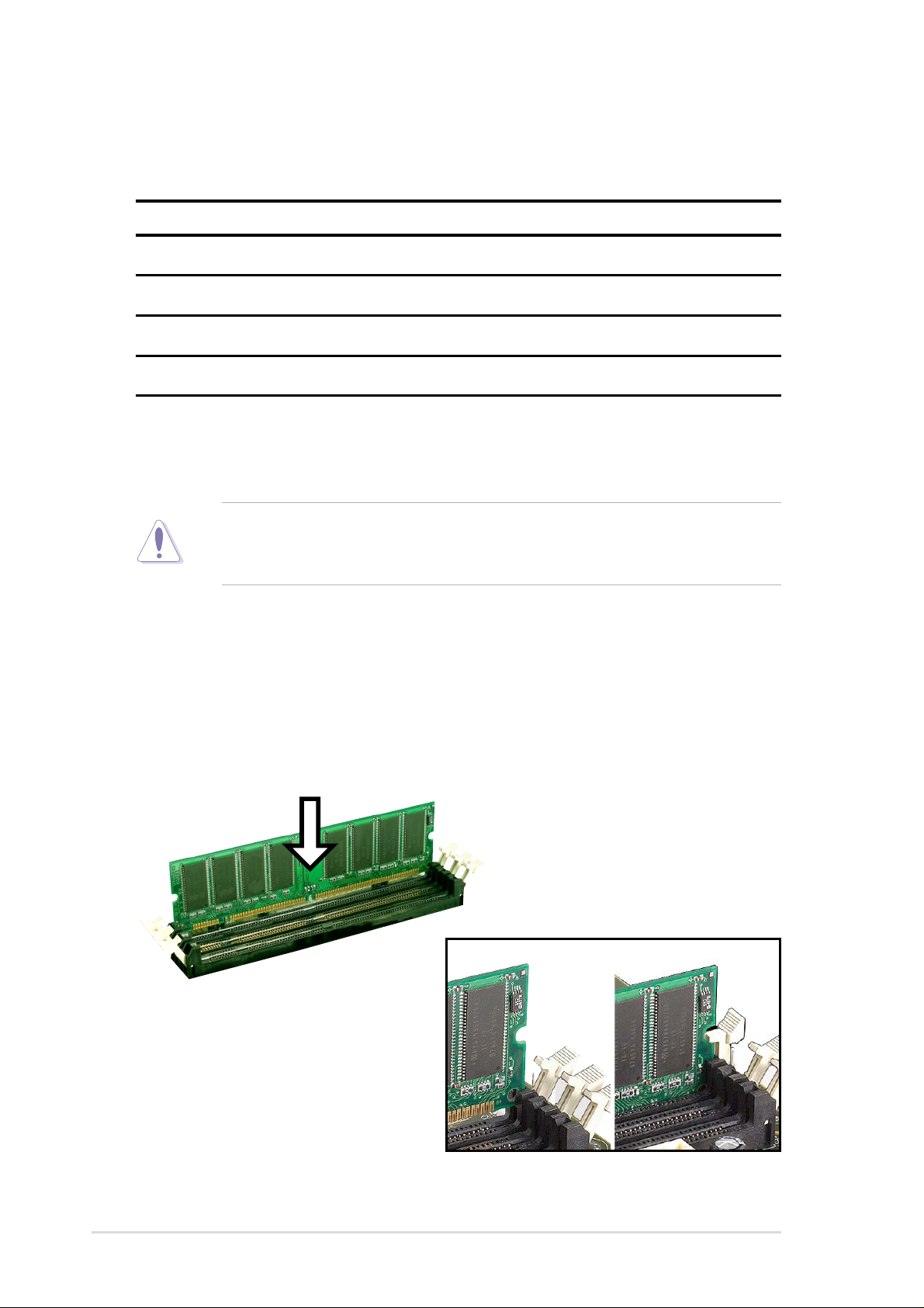
2.5.3 Installing a DIMM
CAUTION! Make sure to unplug the power supply before adding or
removing DIMMs or other system components. Failure to do so may cause
severe damage to both the motherboard and the components.
Installing a DIMM:
1. Unlock a DIMM socket by pressing the retaining clips outward.
2. Align a DIMM on the socket such that the notches on the DIMM exactly
match the notches in the socket.
3. Firmly insert the DIMM into the socket until the retaining clips snap back
in place.
14
Unlocked Retaining Clip Locked Retaining Clip
Chapter 2: Hardware information
2.6 Expansion slots
The motherboard has two PCI slot and one Accelerated Graphics Port (AGP)
slot.. The following sub-sections describe the slots and the expansion cards
that they support.
WARNING! Unplug your power supply when adding or removing
expansion cards or other system components. Failure to do so may cause
you physical injury and damage motherboard components.
2.6.1 Installing an expansion card
Follow these steps to install an expansion card.
1. Before installing the expansion card, read the documentation that came
with it and make the necessary hardware settings for the card.
2. Remove the system unit cover (if your motherboard is already installed
in a chassis).
3. Remove the bracket opposite the slot that you intend to use. Keep the
screw for later use.
4. Align the card connector with the slot and press firmly until the card is
completely seated on the slot.
5. Secure the card to the chassis with the screw you removed earlier.
6. Replace the system cover.
7. Set up the BIOS if necessary.
8. Install the necessary software drivers for your expansion card.
ASUS A7V266-M motherboard user guide
15

2.6.2 Configuring an expansion card
Some expansion cards need an IRQ to operate. Generally, an IRQ must be
exclusively assigned to one function at a time. In a standard design
configuration, 16 IRQs are available but most are already in use. Normally,
6 IRQs are free for expansion cards. If themotherboard has PCI audio
onboard, an additional IRQ will be used. If your motherboard also has MIDI
enabled, another IRQ will be used, leaving 4 IRQs free. Sometimes IRQs
are “shared” by more than one function; in this case, IRQ assignments are
swapped automatically or adjusted through the BIOS firmware.
IMPORTANT! When using PCI cards on shared slots, ensure that the
drivers support “Share IRQ” or that the cards do not need IRQ
assignments. Otherwise, conflicts will arise between the two PCI groups,
making the system unstable and the card inoperable.
Standard Interrupt Assignments
This table lists the standard IRQ assignments for most PC devices.
IRQ Priority Standard Function
0 1 System Timer
1 2 Keyboard Controller
2 N/A Programmable Interrupt
3* 11 Communications Port (COM2)
4* 12 Communications Port (COM1)
5* 13 Sound Card (sometimes LPT2)
6 14 Floppy Disk Controller
7* 15 Printer Port (LPT1)
8 3 System CMOS/Real Time Clock
9* 4 ACPI Mode when used
10* 5 IRQ Holder for PCI Steering
11* 6 IRQ Holder for PCI Steering
12* 7 PS/2 Compatible Mouse Port
13 8 Numeric Data Processor
14* 9 Primary IDE Channel
15* 10 Secondary IDE Channel
*These IRQs are usually available for ISA or PCI devices.IRQ assignments for
this motherboard
16
Chapter 2: Hardware information
Interrupt Request Table for this Motherboard
This table lists the default IRQ assignments forthis motherboard. Use this
table when configuring your system and for resolving IRQ conflicts.
ABCDEFGH
PCI slot 1 —————shared ——
PCI slot 2 ——————used —
Onboard USB controller HC0———used ————
Onboard USB controller HC1———————shared
AGP used ———————
Onboard Audio —————shared ——
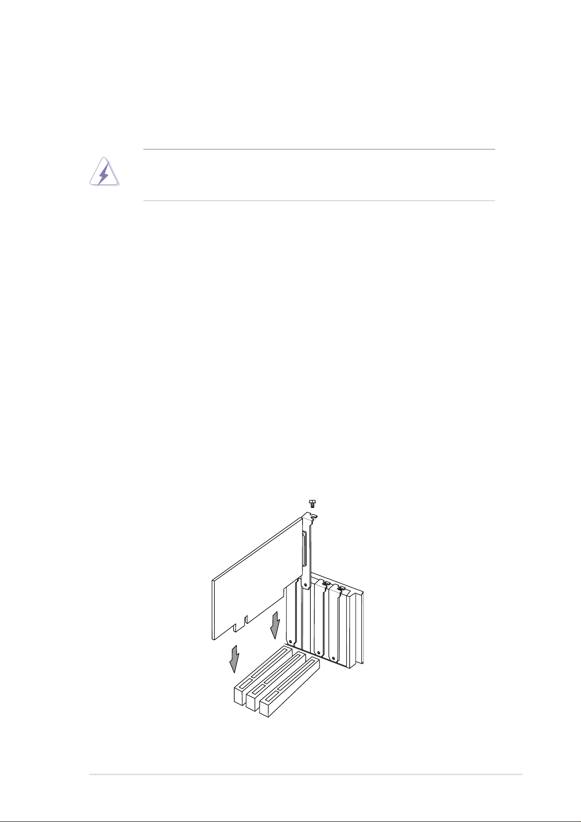
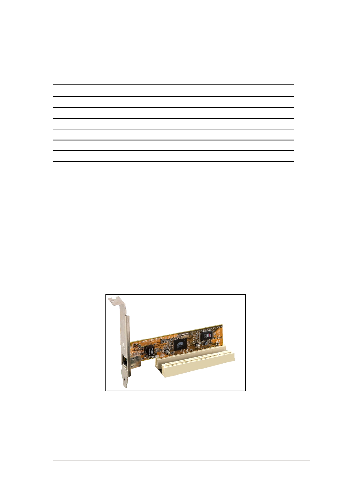
2.6.3 PCI slots
Two 32-bit PCI slots are available on this motherboard. The slots support
PCI cards such as a LAN card, SCSI card, USB card, and other cards that
comply with PCI specifications.
This figure shows a typical PCI card installed into a slot:
ASUS A7V266-M motherboard user guide
17
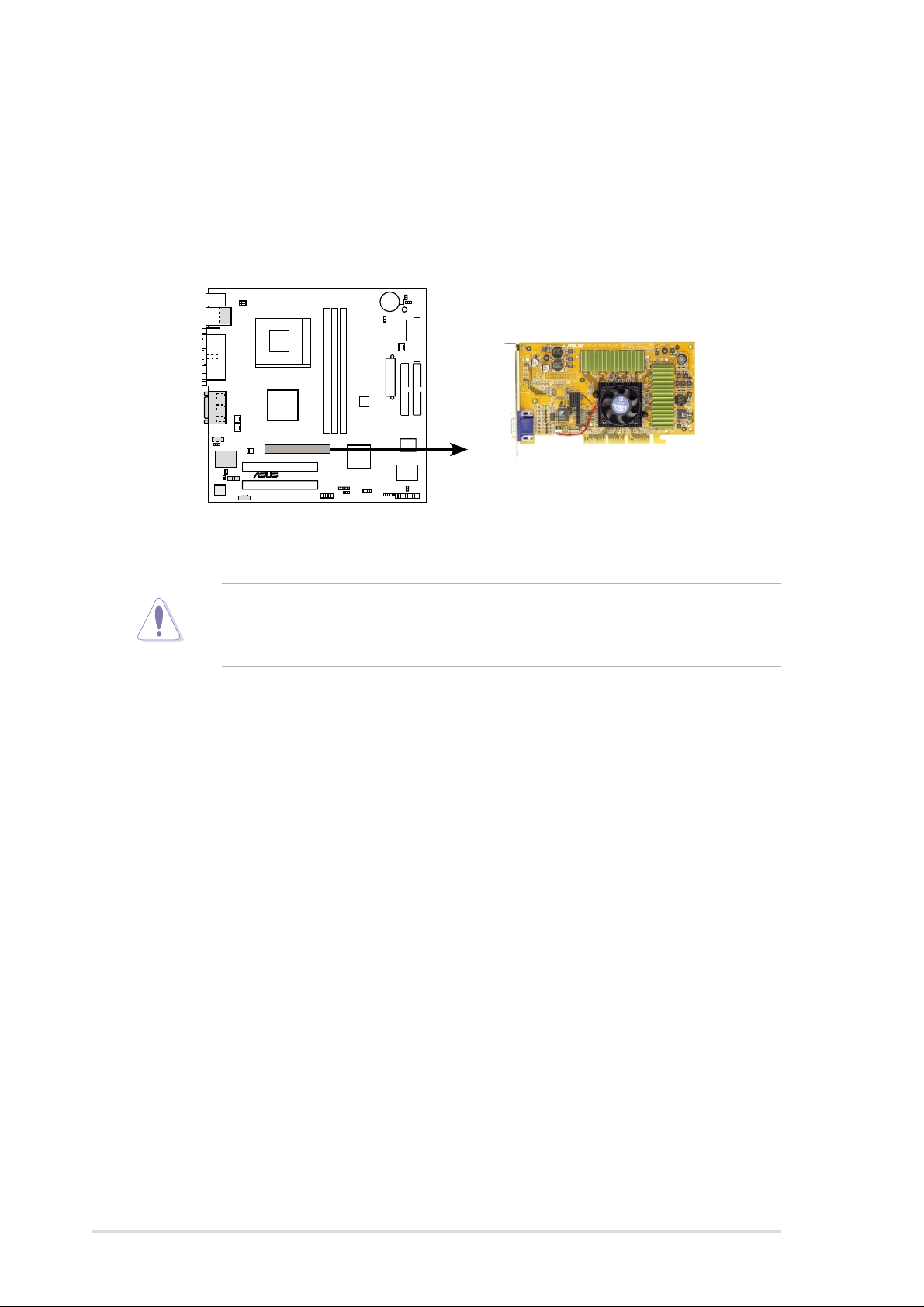
2.6.4 AGP slot
This motherboard provides an Accelerated Graphics Port (AGP 4X) slot to
support AGP graphics cards. Take note of the notches on the card golden
fingers to ensure that they fit the AGP slot on your motherboard. Below is an
example of a +1.5V AGP card.
®
A7V266-M
A7V266-M Accelerated Graphics Port (AGP )
CAUTION! To avoid damaging your AGP/AGP Pro graphics card, your
computer’s power supply should be unplugged before inserting your
graphics card into the slot.
18
Chapter 2: Hardware information
 Loading...