

Assa abloy SW100 User Manual
Besam Low Energy Swing Door Operator
SW100
Installation and Service Manual
1003680-US-4.0 – Issue 2007-10-11
ASSA ABLOY, the global leader in door opening solutions

© All rights in and to this material are the sole property of ASSA ABLOY Entrance Systems AB. Copying, scanning, alterations or modifications are expressly forbidden without the prior written consent of the applicable company within ASSA
ABLOY Entrance Systems AB. Rights reserved for changes without prior notice.
2 Issue 2007-10-11 1003680-US-4.0

Table of content
1 Revision . . . . . . . . . . . . . . . . . . . . . . . . . . . . . . . . . . . . . . . . . . . . . . . . . . . . . . . . . . . . . . . .4
2 Important information . . . . . . . . . . . . . . . . . . . . . . . . . . . . . . . . . . . . . . . . . . . . . . . . . . . . . .5
3 Introduction . . . . . . . . . . . . . . . . . . . . . . . . . . . . . . . . . . . . . . . . . . . . . . . . . . . . . . . . . . . . .6
4 Technical specification . . . . . . . . . . . . . . . . . . . . . . . . . . . . . . . . . . . . . . . . . . . . . . . . . . . . .7
5 How the SW100 works. . . . . . . . . . . . . . . . . . . . . . . . . . . . . . . . . . . . . . . . . . . . . . . . . . . . .8
6 Models . . . . . . . . . . . . . . . . . . . . . . . . . . . . . . . . . . . . . . . . . . . . . . . . . . . . . . . . . . . . . . . .12
7 Part identification . . . . . . . . . . . . . . . . . . . . . . . . . . . . . . . . . . . . . . . . . . . . . . . . . . . . . . . .13
8 Options. . . . . . . . . . . . . . . . . . . . . . . . . . . . . . . . . . . . . . . . . . . . . . . . . . . . . . . . . . . . . . . .14
9 Pre-installation . . . . . . . . . . . . . . . . . . . . . . . . . . . . . . . . . . . . . . . . . . . . . . . . . . . . . . . . . .20
10 Mechanical installation . . . . . . . . . . . . . . . . . . . . . . . . . . . . . . . . . . . . . . . . . . . . . . . . . . . .23
11 Electrical connection . . . . . . . . . . . . . . . . . . . . . . . . . . . . . . . . . . . . . . . . . . . . . . . . . . . . .31
12 Start-up . . . . . . . . . . . . . . . . . . . . . . . . . . . . . . . . . . . . . . . . . . . . . . . . . . . . . . . . . . . . . . .36
13 Changing group of parameters . . . . . . . . . . . . . . . . . . . . . . . . . . . . . . . . . . . . . . . . . . . . .42
14 Cover . . . . . . . . . . . . . . . . . . . . . . . . . . . . . . . . . . . . . . . . . . . . . . . . . . . . . . . . . . . . . . . . .43
15 ANSI / BHMA A156.19 . . . . . . . . . . . . . . . . . . . . . . . . . . . . . . . . . . . . . . . . . . . . . . . . . . . .44
16 Troubleshooting . . . . . . . . . . . . . . . . . . . . . . . . . . . . . . . . . . . . . . . . . . . . . . . . . . . . . . . . .47
17 Planned maintenance checklist . . . . . . . . . . . . . . . . . . . . . . . . . . . . . . . . . . . . . . . . . . . . .49
1003680-US-4.0 Issue 2007-10-11 3

Revision
1Revision
The following pages have been revised:
Page Revision
5 2.3 Glazing materials added
7 Cover depth changed from 5 3/16” to 5 1/8”
4 Issue 2007-10-11 1003680-US-4.0

Important information
2 Important information
2.1 Important notice
To avoid bodily injury, material damage and malfunction of the product, the instructions contained in this manual must be strictly observed during installation, adjustment, repairs and service, etc. Only Besam-trained technicians should be allowed to
carry out these operations.
2.2 Radio and television reception
This equipment generates and uses radio frequency energy and if not installed and
used properly, that is, in strict accordance with the manufacturer's instructions, it may
cause interference to radio and television reception. It has been designed to comply
with the emission limits in accordance with EN 61000-6-3 and EN 61000-6-2 (US
market FCC 47 CFR Part 15B), which are designed to provide reasonable protection
against such interference in a residential installation. However, there is no guarantee
that interference will not occur in a particular installation. If this equipment does
cause interference to radio or television reception, which can be determined by turning the equipment off and on, the user is encouraged to try to correct the interference
by one or more of the following measures:
• Re-orient the receiving antenna.
• Relocate the receiver with respect to the equipment.
• Move the receiver away from the equipment.
• Plug the receiver into a different outlet so that equipment and receiver are on different branch circuits.
• Check that protective earth (PE) is connected.
If necessary, the user should consult the dealer or an experienced radio/television
technician for additional suggestions.
2.3 Glazing materials
The glazing material for swing doors shall comply with ANSI Z97.1
1003680-US-4.0 Issue 2007-10-11 5

Introduction
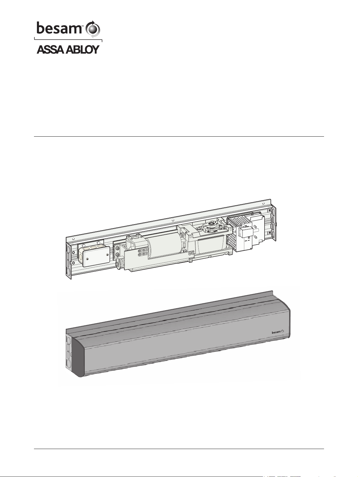
3 Introduction
This manual contains the necessary details and instructions for the installation, maintenance and service of the low energy swing door operator SW100, a universal electro-mechanical operator suitable for all low energy applications of swing doors.
The SW100 can be mounted on either side of the door header for pull or push action,
and is suitable for single or double doors fitted with butt hinges, offset or center
pivots.
The SW100 ensures all-around safety. The operator can be combined with a full
range of sensor products providing swing door safety, but meets also the requirements for a low energy operator without any sensors.
6 Issue 2007-10-11 1003680-US-4.0
Technical specification
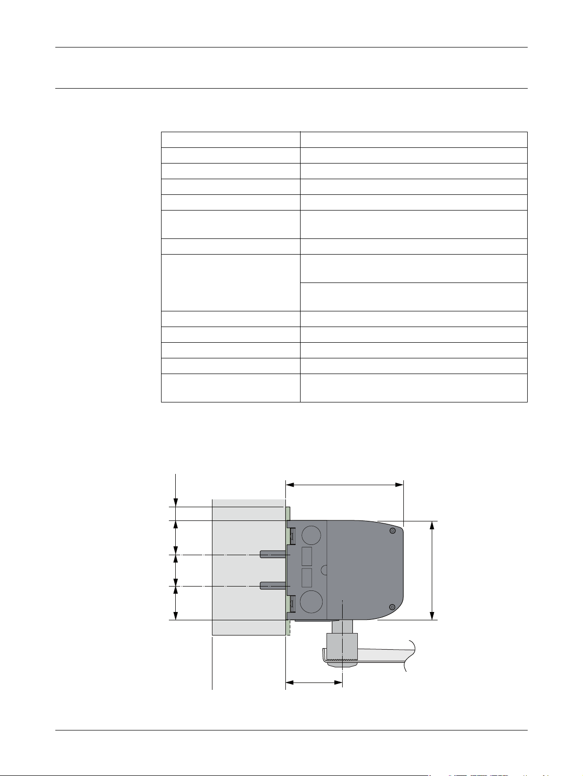
4 Technical specification
Power supply: 120 V AC +10/-15%, 50/60 Hz
Power consumption: max. 75 W
Auxiliary voltage: 24 V DC, max. 400 mA
Internal control fuse: 2 x T 6.3 AH 250 V
Door width: 36-48” (914-1219 mm)
Electro-mechanical locking
device
Door weight: 100-200 lb. (45-90 kg)
Door opening angle: Push arm: 80° - 110°, with reveal 0 - 11
Opening time (0° - 80°): variable between 3 - 6 seconds
Closing time (90° - 10°): variable between 3 - 6 seconds
Hold open time: 1.5-30 seconds
Ambient temperature: -4 °F to +113 °F (-20 °C to +45 °C)
Relative humidity
(non-condensing)
Selectable: 12V DC, max. 500 mA / 24 V DC,
max. 250 mA
13/16”
(0 - 300 mm)
Pull arm: 80° - 110°, with reveal 0 - 5
1/8”
(0 - 130 mm)
Max. 85%
This product is to be installed internally or externally with suitable weather protection.
Class of protection IP 20.
Complies with: IEC 335-1, ANSI/BHMA A156.19 and UL 325.
5 1/8’’
5/8’’
4 5/16’’
11/2’’ 11/2’’13/8’’
2 9/16’’
ILL-01658
1003680-US-4.0 Issue 2007-10-11 7

How the SW100 works
5 How the SW100 works
The low energy swing door operator SW100 uses a DC motor and a gear-reduction
system to drive an arm system, which opens the door. Closing power is provided by a
motor and a clock spring. An electronic control unit uses a motor encoder and a
microprocessor to control the door’s movement.
5.1 Opening
When an opening signal is received by the control unit, the door is opened at the
operator-adjusted opening speed. Before the door is fully open at back check, it slows
automatically to low speed. The motor stops when the selected door opening angle
has been reached. The open position is held by the motor.
If the door is obstructed while opening, it will either stall or stop which can be
selected with a DIP-switch (SOS).
• When stalling - the door will continue to try to open during the hold open time.
• When stopping - the door will, even if hold open time has not expired, close after
2 seconds.
5.2 Closing
When the hold open time has elapsed, the operator will close the door automatically,
using spring force and motor. The door will slow to low speed at latch check before it
reaches the fully closed position. The door is kept closed by spring power or
extended closing force by the motor.
8 Issue 2007-10-11 1003680-US-4.0

How the SW100 works
5.3 Functions on the basic control unit CU-ESD (see also page 32)
5.3.1 Power failure
During power failure the operator acts as a door closer with controlled closing speed.
5.3.2 Spring force
The operator is delivered with spring pre-tension factory set to 210°. If necessary, the
spring tension can be electronically adjusted with a potentiometer to required closing
force.
5.3.3 Extended closing force/torque (CLTQ)
If the potentiometer CLTQ is set to 0°, the door will close with normal spring power. If
the potentiometer is turned clockwise, the motor will increase the closing force/torque.
5.3.4 Power assist (POAS)
If the potentiometer POAS is set to 0°, the door gives no power assist. If the potentiometer is turned clockwise, the motor will give/increase power assist when the door
is opened manually.
5.3.5 Push and go (PAG)
DIP-switch to select “Push and Go” On or Off. “Push and Go” is available from any
door position.
5.3.6 Overhead presence detector (OPD), frame mounted
When an OPD sensor is mounted on the frame or operator header just above the
swing side of the door, it will–when activated–either keep the door open or closed.
The sensor is not active during opening and closing. Lock-out signal must be connected for proper function.
• a closed door will not open, if the OPD detects activity in the field
• an open door will not close, if the OPD detects activity in the field
• during opening, the door will continue to open, even if the OPD detects activity in
the field
• during closing, the door will continue to close, even if the OPD detects activity in
the field
• the OPD is not active in program mode OFF, manually opened door or during battery operation (Power Save Mode).
1003680-US-4.0 Issue 2007-10-11 9

How the SW100 works
5.3.7 Mat
Mat safety means that:
• a closed door will not open, if someone steps on the mat
• an open door will not close, if someone steps on the mat
• during opening, the door will continue to open, even if someone steps on the mat
• during closing, the door will continue to close, even if someone steps on the mat
• opening impulses are prevented during closing, if someone steps on the mat
• the mat is not active in program mode OFF, manually opened door or during battery operation (Power Save Mode).
5.4 Functions on the extension unit EXU-SI (see also page 34)
5.4.1 Kill function
• If kill circuit is closed, the control will ignore all signals and close door(s) at normal speed.
• When kill is no longer active, operator will resume normal operation.
• If kill function must have manual reset, jumper must be removed and reset button
connected to terminal No. 8 and Ground.
• The lock will lock when kill is active regardless of program selector setting.
• The function of the lock can be changed during Kill (see page 42).
5.4.2 Function of locks
• The control has an available output of DC for external locks
• DIP-switches to select 12 or 24 V DC, locked with or without power
• DIP-switch for lock release and potentiometer for opening delay
• DIP-switch for lock kick if door is not fully closed, to overcome binding in the
locking device during closing
• Input to unlock signal from lock. Potentiometer for opening delay is to be set to
max. As soon as unlock signal is received the door will start to open. The output
signal shall be active low.
5.4.3 Program selector
• Input for OPEN, EXIT and OFF (if no program selector, AUTO is default).
5.4.4 Impulses
• Input for Outer impulse, Key impulse and Open/Close impulse.
10 Issue 2007-10-11 1003680-US-4.0

How the SW100 works
5.4.5 Open / close impulse
The impulse will open the door and the door will stay open until a new impulse is
given. If no impulse is given the door will close after 15 minutes. This can be made
infinite by changing group of parameters (see page 42).
Open/close impulse works only in program selection “On”.
5.5 Functions on the extension unit EXU-SA (see also page 35) – optional
5.5.1 Presence impulse approach, door mounted
The presence impulse is active during fully open and closing. The sensor is mounted
to the approach side of the door. Once the door is closed, the sensor is ignored and
will not be active until the next impulse is received.
Note: When installed as a pair of doors, the presence impulse signal will re-open
both doors. The sensor is not active in program mode OFF, manually opened
door or during battery operation (Power Failure Mode).
5.5.2 Presence detection swingpath, door mounted
When a sensor that is mounted on the swing side of a door detects an object, it will
send a command to the control unit to stall the door. If the control unit has received a
short signal from the sensor and there is still hold open time left on the control unit,
the door will continue on its way open if the object has cleared. The inhibit/blanking
potentiometer can be adjusted so that the sensor will avoid detecting a wall or object
near the full open position. Presence detection has a higher priority than presence
impulse.
Note: When installed as a pair of doors the presence detection signal will stop both
doors, except for double egress doors. The behavior for double egress doors
can be changed (see page 42). The sensor is not active in program mode OFF,
manually opened door or during battery operation.
5.5.3 Monitored safety sensors
Both presence impulse and presence detection can be monitored. If a sensor becomes
defective, the operator will not accept any impulses and will then work as a manual
door closer.
5.5.4 Open door indication
A relay output is used to indicate an opening cycle or a specific position of the door.
The indication position is set by adjusting the inhibit/blanking potentiometer.
5.5.5 Error indication
A potential free contact COM/NO/NC for external error indication (see page 48).
1003680-US-4.0 Issue 2007-10-11 11
Models
6 Models
Two main models of the low energy swing door operator SW100 are available:
• Single operator
• Double operator
The operators are non-handed and not dependent on the hinges. The operators suit
both pushing and pulling arm systems.
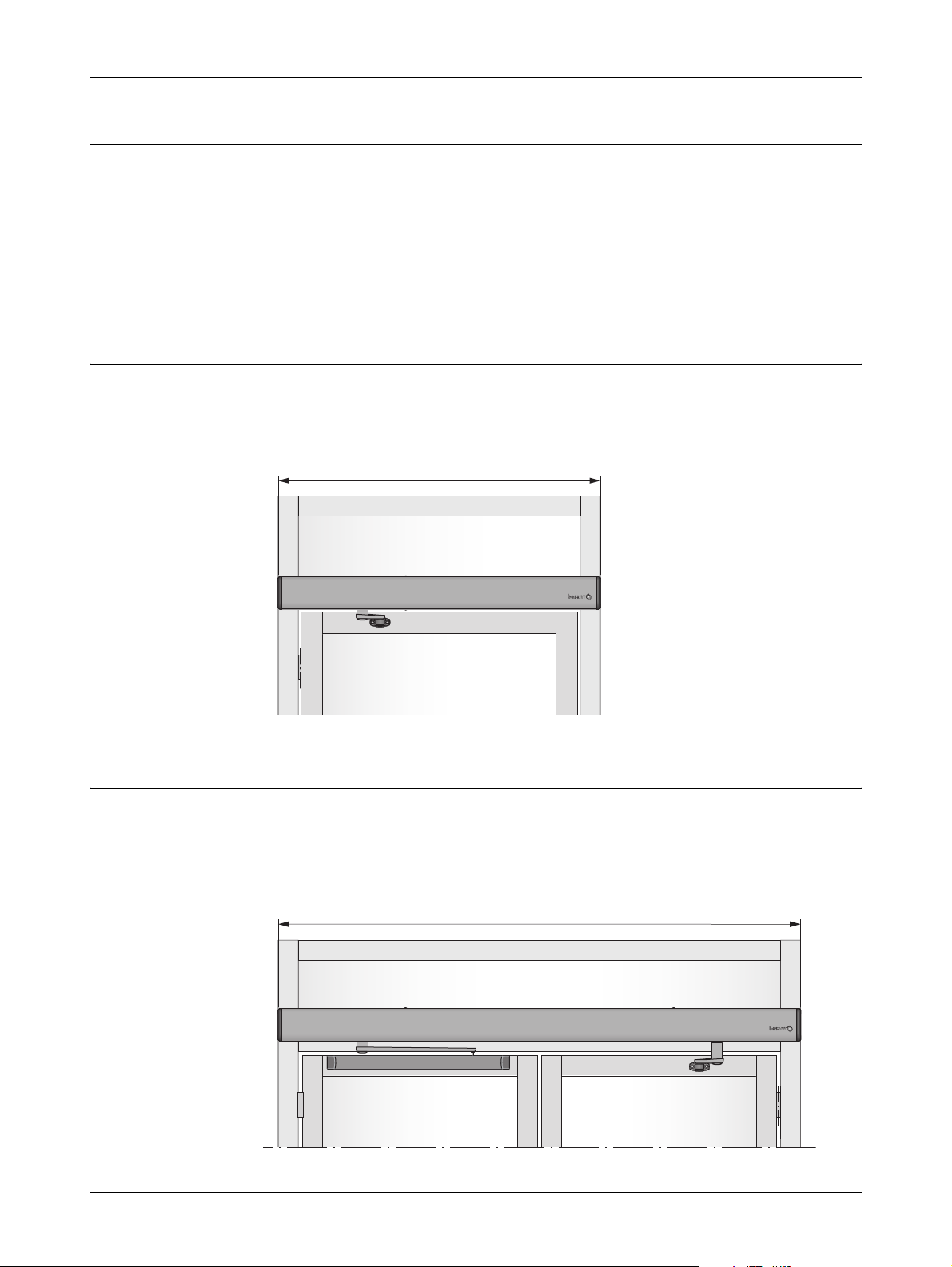
6.1 Single operator
The product is delivered complete with back plate, control unit, end plates and cover.
Length including end plates, L = 39.5” (1003 mm).
Pushing arm system shown.
L
6.2 Double operator (Consult Product Order form for availability)
The product is delivered complete with back plate, control unit, end plates and cover.
Cover length L is optional.
Two operators can be mounted under the same cover to open one door each.
Pushing and pulling arm system shown (double egress).
L
12 Issue 2007-10-11 1003680-US-4.0
Part identification
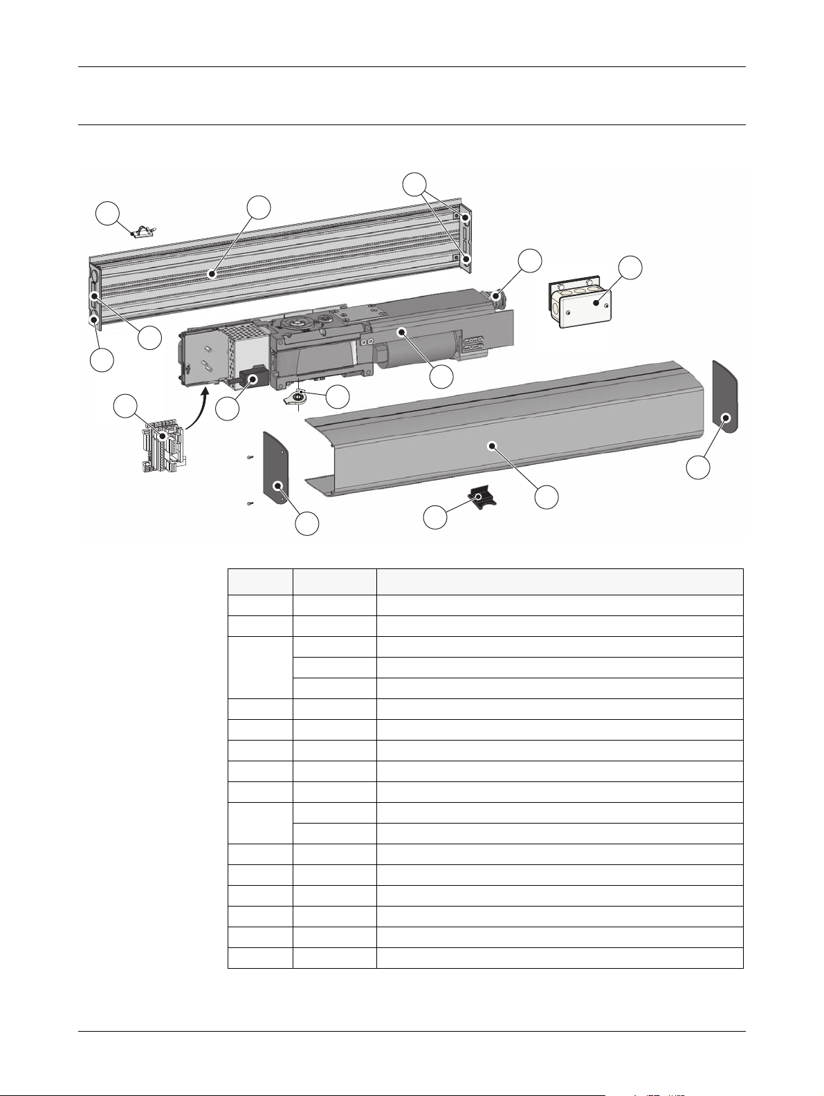
7 Part identification
11
10
1
12
9
7
2
3
4
Item No. P/N Description
1 1003547 Back plate (shorty)
2 1003498 Transmission unit/operator
3 1003532 Control unit CU-ESD
4 1700607 Mains contact
5 1003540 Door stop body
6 1003542 Top end plate
7 1003543 Bottom end plate
8 1003546 Main cover (shorty)
9 1003581 Power On/Off switch
10 1003578 Cable holder (50 pcs)
11 – Knockouts for cable inlet
12 – Belt tension device
13 1003545 Fill cover (output shaft)
14 1004437 Connection box
– 1003583 Sync cable – optional
5
8
6
1003554 EXU-SI (Kit to extend the security functions) – optional
1003557 EXU-SA (Kit to extend the safety functions) – optional
1003582 On/Off/Hold open switch – optional
13
14
6
1003680-US-4.0 Issue 2007-10-11 13
Options
8Options
8.1 Arm systems
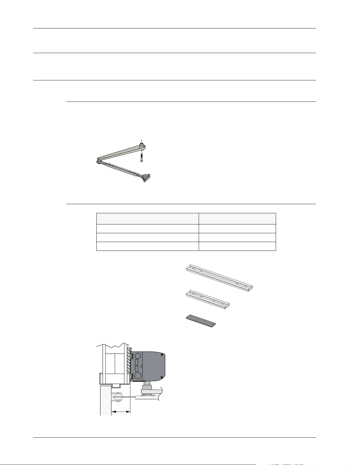
8.1.1 Arm system, PUSH P/N: 1003576
This arm system is delivered with drive arm, telescopic part and door fitting. It is
used if the operator is installed on the wall on the opposite side of the door swing, and
approved for fire door application.
PUSH
8.1.2 PUSH-arm extensions
Reveal = X Extension
Up to 4-1/8” (0-105 mm) None (standard arm)
4-1/8” to 8-11/16” (105-220 mm) 13-9/16” (345 mm)
8-11/16” to 11-13/16” (220-300 mm) 9-1/16” (230 mm) + Joint part
13-9/16” (345 mm) extension
P/N: 21-06-17305
9-1/16” (230 mm) extension
P/N: 21-06-17304
Joint part
P/N: 21-06-17319
X
14 Issue 2007-10-11 1003680-US-4.0
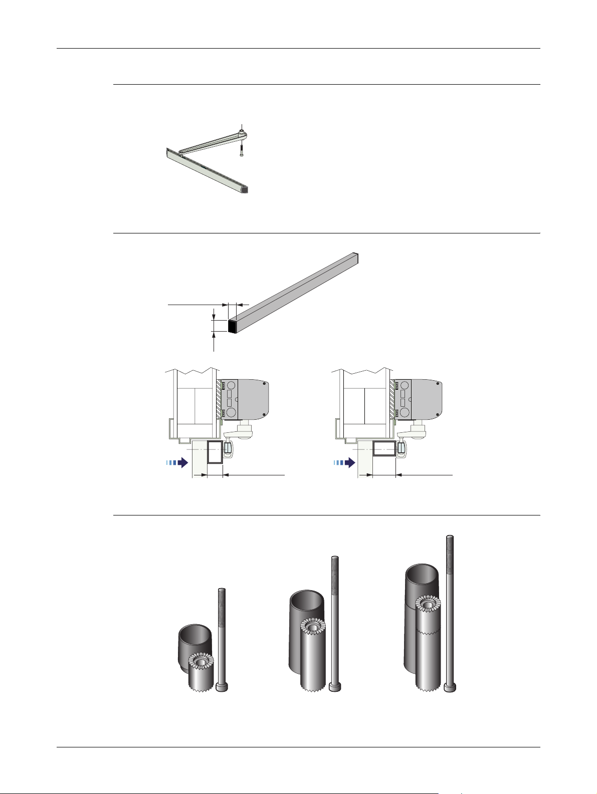
8.1.3 Arm system, PULL P/N: 1003577
This arm system is delivered with drive arm, guide shoe and door fitting.
PULL
8.1.4 Reveal spacer, PULL P/N: 173804BK
40 mm (1-9/16")
Options
60 mm
(2-3/8")
40 (1-9/16") 60 (2-3/8")
8.1.5 Drive shaft extension kits
20 mm
(3/4")
70 mm
(2-3/4")
50 mm
(2")
P/N: 21-03-205
1003680-US-4.0 Issue 2007-10-11 15
P/N: 21-03-206
P/N: 21-03-207
Options
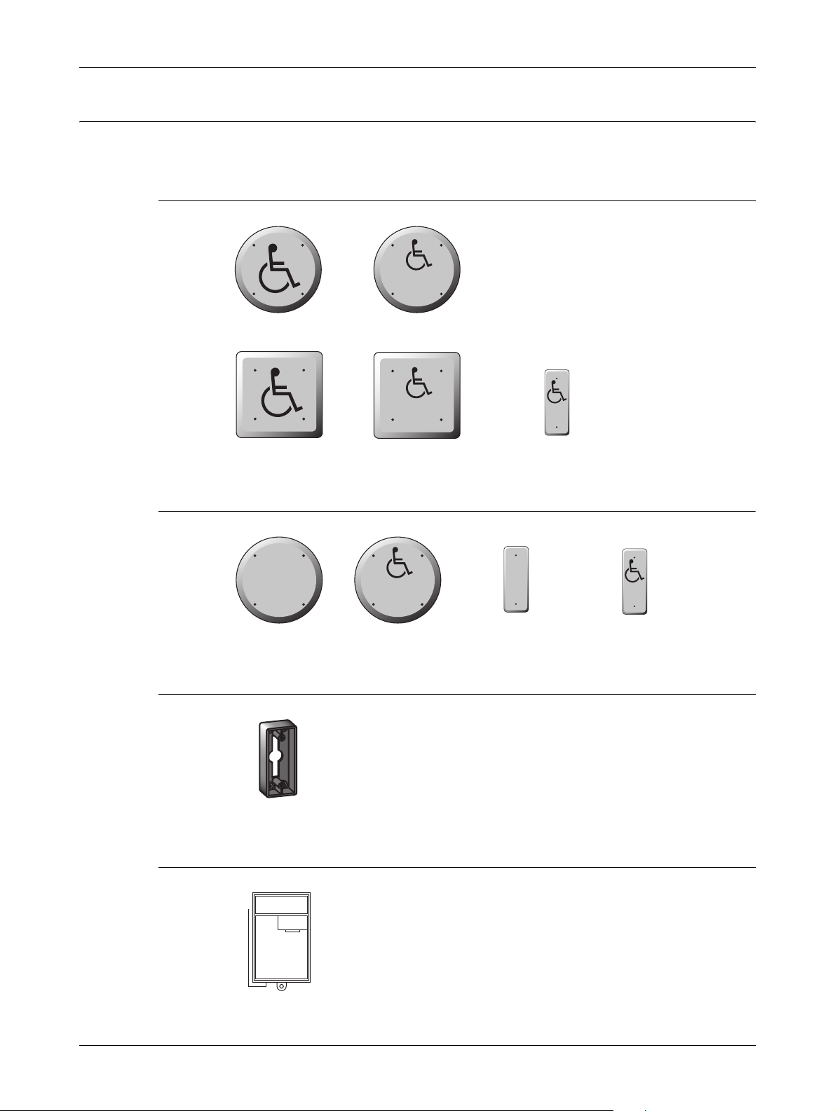
8.2 Push plates
For disable use, mount push plate 31” above floor level.
8.2.1 Push plates
PRESS
TO OPEN
P/N: 75-02-101
P/N: 75-02-107
P/N: 75-02-102
PRESS
TO OPEN
P/N: 75-02-108
8.2.2 Remote transmitter push plates
PUSH
TO OPEN
P/N: 75-02-273
PUSH
TO OPEN
P/N: 75-02-272
8.2.3 Installation box for narrow plates
P/N: 75-02-280
PUSH
TO
OPEN
P/N: 75-02-269
P/N: 75-02-270
PUSH
TO
OPEN
P/N: 75-21-002
8.2.4 Remote receiver
P/N: 75-02-271
16 Issue 2007-10-11 1003680-US-4.0
 Loading...