


DC3200

IMPORTANT:
BEFORE
INSTALLING:
TO DETERMINE
HAND OF
YOUR DOOR:
An improperly installed or incorrectly adjusted door closer may cause property
damage or personal injury; and will void product warranty.
To avoid personal injury, DO NOT DISASSEMBLE THIS DOOR CLOSER BODY.
Door closers must be securely fastened to a properly reinforced door and frame
with fasteners provided.
Door closers with the “A1” HOLD OPEN ARM option are not permitted to be
installed in fire door assemblies.
LEFT
HAND
DOOR
RIGHT
HAND
DOOR
Size of Door & Door Closer
Type
of
Installation
Interior
Exterior
In-swinging
Exterior
Out-swinging
Recommended
Closer Size
**Max.
Opening
Force
lbs/f
2 4
3 0
3 6
4 0
4 6
5 0
' "
' "
' "
' "
' "
' "
2 4
2 6
3 0
3 6
4 0
4 6
' "
' "
' "
' "
' "
' "
2 6
3 0
3 6
*4 0
' "
' "
' "
' "
2 6
3 0
*3 6
*4 0
' "
' "
' "
' "
3 0
3 6
4 0
*4 6
' "
' "
' "
' "
1
2
3
4
5
6
8
14
16
22
24
26
8
14
16
22
24
26
1
2
3
4
5
6
Regular &
Top Jamb
Parallel
Arm
Universal Door Closers
RHR
LHR
The door closer's power size adjustment feature may require adjustment to its
lowest setting to comply with ADA opening force guidelines.
Regular Arm
Parallel Arm
Jamb Mount
80-9330-3000-152 Rev. 05/12
Installation Instructions
For Non-Hold Open or “A1”
Hold Open Arm Options
See pages
2 & 3
See pages
4 & 5
See pages
6 & 7
®
ASSA ABLOY
DC3200 Series
Multi-Sized 1 thru 6
DC3200
DC3210
DC3220
ADA compliant closers are: DC3200, DC3210, DC3220
The Americans with Disabilities Act (ADA) requires that doors having door closers
have an opening force not to exceed 5 lbf. for interior doors, 8.5 lbf exterior doors.
Use standard templating for regular arm and parallel arm applications. Jamb
mounted applications use the template for 140° door opening to achieve the
required opening force.
**NOTE: These forces are for standard templating with bearing type hinges and do not account for pressure differentials and draft.
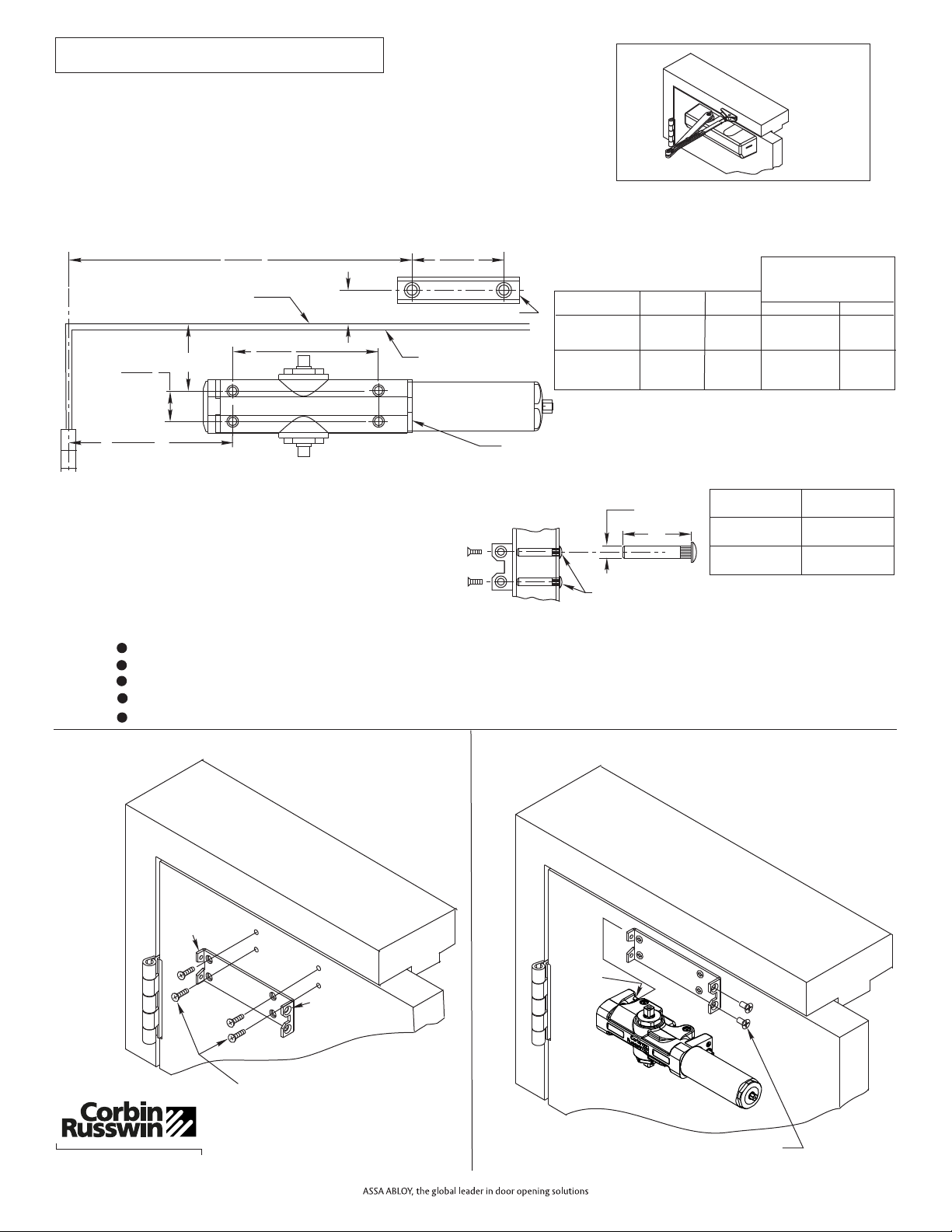
Installation Instructions
Regular Arm Application
CLOSER BRACKET
Mark Door and Jamb (for closer bracket and arm bracket)
If top rail is 2-1/2 (64mm) or greater, use template FM131C provided.
If top rail is 1-3/4 (44mm) to 2-7/16 (62mm), see MOUNTING DIMENSIONS chart.
"
"
MOUNTING DIMENSIONS
TOP RAIL
A
B
MIN. CLEARANCE
REQUIRED OVER
DOOR
NHO
2-1/2 & OVER
(64mm)
"
1
(25.4mm)
"
7/8
(23mm)
"
1-3/4 MIN.
(44mm)
"
5/8
(16mm)
"
1-1/4
(32mm)
"
1-1/2
(39mm)
"
1-7/8
(48mm)
"
1-11/16
(43mm)
"
2-1/16
(53mm)
"
1. Template
HO
Regular Arm
NOTES:
Check hand of door, see page 1.
Right Hand Application Shown. Left Hand Opposite.
Dimensions given in inches (mm). Do Not Scale Drawing.
Closer must be installed in a true horizontal plane to ensure proper closer performance.
Door opening (up to 180°) is dependent upon door, frame, wall and hinge/pivot conditions permitting.
2. Install Closer Bracket
3. Mount Closer Body to Closer Bracket
Pin Hole
End
Countersunk
Hole End
Pins
(2)
Page 2
To obtain extra closing force add 3 (77mm) to dimensions marked.
This will limit degree of door opening to 110°.
"
B
A
2-1/4
(57.2)
*10-5/8
(270)
*7-1/2
(191)
FRAME LINE
TOP OF DOOR
C
L
HINGE OR PIVOT
ARM BRACKET
*
4-5/16
(109.5)
1
(25.4)
L
3/8
(10)
1/4-20 THREAD
Drill thru 9/32 (7.1) Enlarge to
3/8 (9.5) Dia. This Side Only
(4 Places)
DOOR
THICKNESS
SEX NUT
LENGTH “L”
1-3/8 (35mm)"
1-3/4 (44mm)
& OVER
"
1-9/32 (33mm)"
1-21/32 (42mm)"
MOUNTING SCREW SPECIFICATIONS
ARM AND CLOSER BRACKET
}
or
{
Option M54:
Sex nuts, furnished
when ordered
1/4-20 oval head machine screw
or 1/4-14 self-drilling screw.
3/16 (4.8) diameter pilot hole
required for Wood Applications.
1/4-20 x 1/2 OHMS (2)
1/4-14 x 1-1/2 OH Self-Drilling (4)
or
1/4-20 x 3/4 OHMS w/ Sex Nuts (4)
(M54 Option)
®
ASSA ABLOY
80-9330-3000-152 Rev. 05/12
DC3200 Series
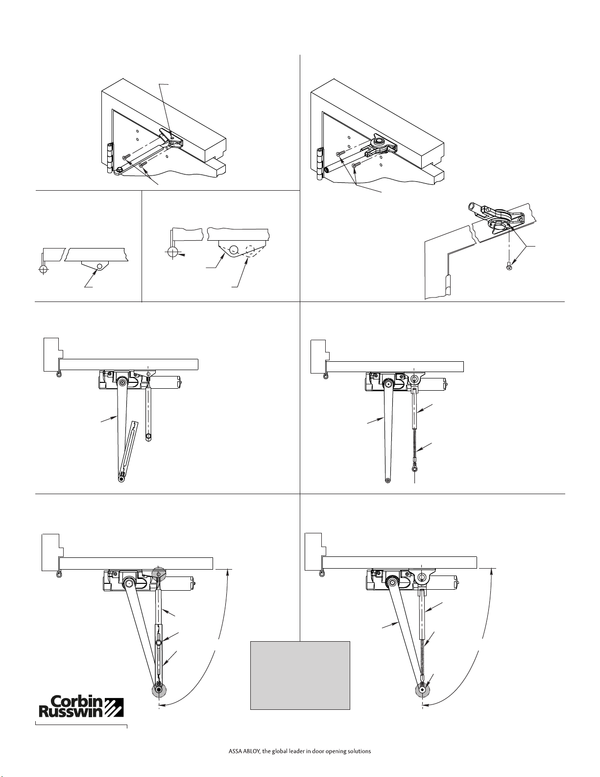
NON-HOLD OPEN ARM ONLY:
Normal mounting position.
Position with pivot point
away from hinge.
Away from
hinge
4a. Attach Arm Bracket to Frame
For Additional 15% Closing Force
Reposition arm mounting bracket so that
pivot point is toward hinge.
FOR MAXIMUM
POWER
FOR REGULAR
POWER
Hinge
Standard Position
HOLD OPEN ARM (A1 OPTION ONLY):
4b. Attach Arm Bracket to Frame
HOLD OPEN ARM:
Position so that dial
screw is on
UNDERSIDE of bracket
For Adjustments See Page 8
Page 3
Regular Arm Application (Continued)
5a. Position Arm on Closer
Main arm projects straight out at 90° angle to door.
5b. Position Arm on Closer
Main arm projects straight out at 90° angle to door. Remove main
arm screw from elbow joint and disassemble arm. Thread the rod
into the Arm Bracket as shown below.
NON-HOLD OPEN ARM ONLY:
HOLD OPEN ARM ONLY:
MAIN ARM
MAIN ARM
THREADED
ROD
ARM
BRACKET
6a. Preload and Adjust Arm
Open door and slide arm rod into arm loop. Close door, swing arms
so adjusting arm is 90° to frame. With 7/16 wrench INSTALL and
TIGHTEN SCREW SECURELY.
"
Extended Maintenance
Lubricate Arm periodically
shaded points with a drop or
two of appropriate lubricant.
NOTE: When lubricating a
Hold Open Arm, DO NOT
use any lubricant on the
Holding Surface components.
at
ARM
LOOP
ARM ROD
SCREW
90°
NON-HOLD OPEN ARM ONLY:
6b. Preload and Adjust Arm
While door is closed, adjust the Threaded Arm in the Arm Bracket
until the bearing fits back onto the elbow joint on the Main Arm at 90°
as shown below. RE-INSTALL AND TIGHTEN SCREW SECURELY.
HOLD OPEN ARM ONLY:
ARM
BRACKET
THREADED
ARM
SCREW
90°
DIAL
SCREW
MAIN ARM
1/4-14 x 1-1/2 OH Self-Drilling (4)
Pivot (away from hinge)
1/4-14 x 1-1/2 OH Self-Drilling (4)
®
ASSA ABLOY
80-9330-3000-152 Rev. 05/12
 Loading...