


 Loading...
Technical Manual
VingCard Classic RFID

Copyrights
The information in this document is subject to change at the sole discretion of ASSA ABLOY without notice.
Any use, operation or repair in contravention of this document is at your own risk. ASSA ABLOY does not assume any responsibility for incidental or consequential damages arising from the use of this manual.
All information and drawings in this document are the property of ASSA ABLOY. Unauthorized use and reproduction is prohibited.
VingCard and Elsafe are registered trademarks of ASSA ABLOY.
ASSA ABLOY Hospitality |
2 |

Table of contents |
|
FCC/IC.................................................................................................statements |
5 |
FCC statements for LCU |
|
................................................................................................................. |
5 |
ISED (IC) statements for LCU |
|
................................................................................................................. |
5 |
FCC statements for ZigBee endnode |
|
................................................................................................................. |
7 |
ISED (IC) statements for ZigBee endnode |
|
................................................................................................................. |
7 |
OEM.............................................................................................................................responsibilities |
8 |
1. Introduction................................................................................................. |
9 |
1.1 Introduction to LCU 6351 |
|
................................................................................................................. |
9 |
2. External.................................................................................................dimension requirements |
10 |
2.1 External strike dimensions |
|
................................................................................................................. |
11 |
2.2 Direction of opening |
|
................................................................................................................. |
13 |
2.3 Cut-outs |
|
................................................................................................................. |
13 |
3. To.................................................................................................install the lock |
14 |
3.1 Exploded view |
|
................................................................................................................. |
14 |
..3.1...........................................................................................................................1 RFID cut-out |
14 |
..3.1...........................................................................................................................2 Mag cut-out (for upgrade from mag) |
15 |
..3.1...........................................................................................................................3 RFID specific parts |
16 |
..3.1...........................................................................................................................4 Upgrade kits |
16 |
..3.1...........................................................................................................................5 Online by ZigBee |
17 |
3.2 To install the lock |
|
................................................................................................................. |
17 |
4. Installation.................................................................................................checklist |
21 |
4.1 Installation check |
|
................................................................................................................. |
21 |
4.2 Operational check |
|
................................................................................................................. |
21 |
4.3 Security function check |
|
................................................................................................................. |
21 |
5. Commissioning................................................................................................. |
22 |
6. Maintenance................................................................................................. |
23 |
6.1 To release the cover from the RFID module |
|
................................................................................................................. |
23 |
7. Service.................................................................................................functions |
23 |
Appendix.................................................................................................A: ANSI DA ADB |
24 |
ADB strike ................................................................................................................. |
24 |
All.............................................................................................................................frames (wooden and steel frames) |
25 |
Mortise............................................................................................................................. |
25 |
Cylinder for ADB |
|
................................................................................................................. |
26 |
To.............................................................................................................................install the cylinder |
26 |
ASSA ABLOY Hospitality |
3 |

Appendix.................................................................................................B: ANSI DB ADB |
27 |
ADB strike ................................................................................................................. |
27 |
All.............................................................................................................................frames (wooden and steel frames) |
28 |
Mortise............................................................................................................................. |
28 |
Cylinder for ADB |
|
................................................................................................................. |
29 |
To.............................................................................................................................install the cylinder |
29 |
Appendix.................................................................................................C: EURO ADB |
30 |
EURO ADB lock case |
|
................................................................................................................. |
30 |
Cylinder for ADB (escutcheons with cylinder) |
|
................................................................................................................. |
32 |
Appendix D: Preparing escutcheons (normally |
|
................................................................................................. |
33 |
not needed) |
|
ASSA ABLOY Hospitality |
4 |

FCC/IC statements
FCC (Federal Communications Commission) statements for LCU
This device complies with Part 15 of the FCC Rules. Operation is subject to the following two conditions:
(1)this device may not cause harmful interference, and
(2)this device must accept any interference received, including interference that may cause undesired operation.
Exposure statement:
This portable device with its antenna complies with FCC RF exposure limits for general population / uncontrolled exposure. The antenna used for this device must not be co-located or operating in conjunction with any other antenna or transmitter. Use only the supplied antenna.
This equipment complies with FCC radiation exposure limits set forth for an uncontrolled environment.
This transmitter must not be co-located or operating in conjunction with any other antennas or transmitters.
Changes or modifications not expressly approved by the party responsible for compliance could void the user's authority to operate the equipment.
Note: This equipment has been tested and found to comply with the limits for a Class B digital device, pursuant to part 15 of the FCC Rules. These limits are designed to provide reasonable protection against harmful interference in a residential installation. This equipment generates, uses and can radiate radio frequency energy and, if not installed and used in accordance with the instructions, may cause harmful interference to radio communications. However, there is no guarantee that interference will not occur in a particular installation. If this equipment does cause harmful interference to radio or television reception, which can be determined by turning the equipment off and on, the user is encouraged to try to correct the interference by one or more of the following measures:
-Reorient or relocate the receiving antenna.
-Increase the separation between the equipment and receiver.
-Connect the equipment into an outlet on a circuit different from that to which the receiver is connected.
-Consult the dealer or an experienced radio/TV technician for help.
The LCU must be labeled to say 'FCC ID: Y7V-LCU6351C1'.
ISED (IC) statements for LCU
This device complies with Industry Canada licence-exempt RSS standard CAN ICES-3 (B)/NMB-3(B) B. Operation is subject to the following two conditions:
(1)this device may not cause interference, and
(2)this device must accept any interference, including interference that may cause undesired operation of the device.
Le présent appareil est conform aux CNR d’Industrie Canada applicables aux appareils radio exempts de licence. L’exploitation est autorisée aux deux conditions suivantes:
(1)l'appareil ne doit pas produire de brouillage, et
(2)l’utilisateur de l'appareil doit accepter tout brouillage radioélectrique subi, même si le brouillage est susceptible d’en compromettre le fonctionnement.
ASSA ABLOY Hospitality |
5 |
66 1100 057-C |

Exposure statement:
This portable device with its antenna complies with FCC RF exposure limits for general population / uncontrolled exposure. The antenna used for this device must not be co-located or operating in conjunction with any other antenna or transmitter. Use only the supplied antenna.
Under Industry Canada regulations, this radio transmitter may only operate using an antenna of a
type and maximum (or lesser) gain approved for the transmitter by Industry Canada. To reduce potential radio interference to other users, the antenna type and its gain should be so chosen that the equivalent isotropically radiated power (e.i.r.p.) is not more than that necessary for successful communication.
This radio transmitter IC:9514A-LCU6351C1 has been approved by Industry Canada to operate with the antenna type listed below with the indicated maximum permissible gain and required antenna impedance. Antenna types not included in this list, having a gain greater than the maximum gain indicated for that type, are strictly prohibited for use with this device.
Name/Model |
Gain |
Impedance |
Inverted F-antenna |
3.0 dBi |
50 ohm |
The term "IC" before the equipment certification number only signifies that the Industry Canada technical specifications were met.
Le terme "IC" devant le numéro de certification signifie seulement que les specifications techniques Industrie Canada ont été respectées.
ASSA ABLOY Hospitality |
6 |
66 1100 057-C |

FCC (Federal Communications Commission) statements
for ZigBee endnode
This device complies with Part 15 of the FCC Rules. Operation is subject to the following two conditions:
(1)this device may not cause harmful interference, and
(2)this device must accept any interference received, including interference that may cause undesired operation.
Exposure statement:
This portable device with its antenna complies with FCC RF exposure limits for general population / uncontrolled exposure. The antenna used for this device must not be co-located or operating in conjunction with any other antenna or transmitter. Use only the supplied antenna.
This equipment complies with FCC radiation exposure limits set forth for an uncontrolled environment.
This transmitter must not be co-located or operating in conjunction with any other antennas or transmitters.
Changes or modifications not expressly approved by the party responsible for compliance could void the user's authority to operate the equipment.
Note: This equipment has been tested and found to comply with the limits for a Class B digital device, pursuant to part 15 of the FCC Rules. These limits are designed to provide reasonable protection against harmful interference in a residential installation. This equipment generates, uses and can radiate radio frequency energy and, if not installed and used in accordance with the instructions, may cause harmful interference to radio communications. However, there is no guarantee that interference will not occur in a particular installation. If this equipment does cause harmful interference to radio or television reception, which can be determined by turning the equipment off and on, the user is encouraged to try to correct the interference by one or more of the following measures:
-Reorient or relocate the receiving antenna.
-Increase the separation between the equipment and receiver.
-Connect the equipment into an outlet on a circuit different from that to which the receiver is connected.
-Consult the dealer or an experienced radio/TV technician for help.
The endnode must be labeled to say 'FCC ID: Y7V-683081150C1'.
ISED (IC) statements for ZigBee endnode
This device complies with Industry Canada licence-exempt RSS standard CAN ICES-3 (B)/NMB-3(B) B. Operation is subject to the following two conditions:
(1)this device may not cause interference, and
(2)this device must accept any interference, including interference that may cause undesired operation of the device.
Le présent appareil est conform aux CNR d’Industrie Canada applicables aux appareils radio exempts de licence. L’exploitation est autorisée aux deux conditions suivantes:
(1)l'appareil ne doit pas produire de brouillage, et
(2)l’utilisateur de l'appareil doit accepter tout brouillage radioélectrique subi, même si le brouillage est susceptible d’en compromettre le fonctionnement.
Exposure statement:
This portable device with its antenna complies with FCC RF exposure limits for general population / uncontrolled exposure. The antenna used for this device must not be co-located or operating in conjunction with any other antenna or transmitter. Use only the supplied antenna.
Under Industry Canada regulations, this radio transmitter may only operate using an antenna of a
type and maximum (or lesser) gain approved for the transmitter by Industry Canada. To reduce potential
ASSA ABLOY Hospitality |
7 |
66 1100 057-C |

radio interference to other users, the antenna type and its gain should be so chosen that the equivalent isotropically radiated power (e.i.r.p.) is not more than that necessary for successful communication.
This radio transmitter IC9514A-683081150C1 has been approved by Industry Canada to operate with the antenna type listed below with the indicated maximum permissible gain and required antenna impedance. Antenna types not included in this list, having a gain greater than the maximum gain indicated for that type, are strictly prohibited for use with this device.
Name/Model |
Gain |
Impedance |
Inverted F-antenna |
3.0 dBi |
50 ohm |
The term "IC" before the equipment certification number only signifies that the Industry Canada technical specifications were met.
Le terme "IC" devant le numéro de certification signifie seulement que les specifications techniques Industrie Canada ont été respectées.
OEM responsibilities
The endnode module has been certified for integration into products only by OEM integrators under the following conditions:
1.The antenna must be installed such that a minimum separation distance of 20cm is maintained between the radiator (antenna) and all persons at all times.
2.The transmitter module must not be co-located or operating in conjunction with any other antenna or transmitter.
As long as the two conditions above are met, further transmitter testing will not be required. However, the OEM integrator is still responsible for testing their end-product for any additional compliance requirements required with these modules installed (e.g., digital device emissions, PC peripheral requirements, etc.).
Important note: In the event that these conditions can not be met (for certain configurations or co-location with another transmitter), then Industry Canada certification is no longer considered valid and the IC Certification Number can not be used on the final product. In these circumstances, the OEM integrator will be responsible for re-evaluating the end products (including the transmitter) and obtaining a separate Industry Canada authorization.
The OEM of the respective module must only use the approved antenna listed above, which have been certified with this module. The OEM integrator has to be aware not to provide information to the end user regarding how to install or remove this RF module or change RF related parameters in the user’s manual of the end products.
ASSA ABLOY Hospitality |
8 |
66 1100 057-C |
1. Introduction
The VingCard Classic RFID lock is a standalone electronic lock with RFID (radio frequency identification) technology, which can also be online by ZigBee 1. VingCard Classic RFID is compatible with the Visionline system. The lock has LED signals and can also be configured for sound signals 2; see information about configuring the beeper in section 1.1 below. Note: The VingCard Classic RFID lock can be used
at new installations, or as an upgrade from VingCard Classic mag; in the latter case, only add the RFID reader by replacing the top cover.
1.1 Introduction to LCU 6351
LCU 6351 has the same dimensions and service contact as the previous LCU version (6334), but there are also some differences which are described below.
Instead of having a separate BLE module, the LCU now includes the BLE radio. Initialization of BLE is however done in the same way as for previous LCU, i.e. mark 'Include BLE configuration data' under Initialize lock in Lock Service 3G when initializing the lock/elevator controller/remote controller. As for previous LCU, if the signal strength should be changed from the default value 0 dBm and/or if seamless mode is applicable go to Configure lock in Lock Service 3G; choose 'Send configuration data (BLE)' and make the necessary settings for
'Tx power' and 'seamless mode'. See Quick reference guide Lock Service 3G for details about the Initialize lock and Configure lock operations.
Minimum Lock Service 3G version is 2.3.0.2, which includes the below minimum firmware versions:
-3.17.37.4 (standard lock)
-3.18.37.4 (elevator controller)
-3.20.37.4 (remote controller)
-3.40.37.4 (VingCard Allure standard lock)
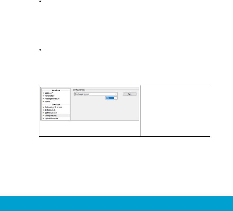
•LCU 6351 can be configured to give sound signals:
1.Connect the service cable to the lock/elevator controller/ remote controller.
2.Choose Configure lock in the left pane of Lock Service 3G.
3.In the upper drop-down-menu, choose 'Configure beeper'.
4.In the lower drop-down-menu, choose 'ON'.
5.Click the Set button.
1)See User manual Online option for more details about the ZigBee network etc.
2)For information about different LED and sound signals which the lock can give,
see the appendix 'Lock LEDs and sounds and what they mean' in User manual Visionline.
Continued on next page
ASSA ABLOY Hospitality |
9 |
66 1100 057-C |

• LCU 6351 can (in addition to the regular green/yellow/red LED signals) be configured to show a flashing blue LED signal when the BLE radio is searching for a mobile device to connect to:
1. Connect the service cable to the lock/elevator controller/ remote controller.
2. Choose Configure lock in the left pane of Lock Service 3G.
3. In the upper drop-down-menu, choose 'Configure blue LED'.
4. In the lower drop-down-menu, choose 'ON'.
5. Click the Set button.
2. External dimension requirements
Before starting the installation, check the below dimensions (in mm/inches).
Note 1: Allow at least 25.4 mm (1)'' in depth for deadbolt.
Warning: When the deadbolt is thrown, the door cannot be opened with a metal key in case of emergency, if the cut-out is less than 25.4 mm (1)'' deep.
Note 2: Gap between lock front-end and strike must not exceed 3 mm (1/8)''.
Note 3: The lock front-end plate can be delivered in either 25 mm (1)'', 28 mm (1 1/8)'' or US Standard 32 mm (1 1/4)'' widths.
Note 4: Minimum door thickness required is 34 mm (1 11/32)''. Spacer must be on doors that are less than 34 mm (1 11/32)'' thick.
ASSA ABLOY Hospitality |
10 |
66 1100 057-C |

Figure 2: Lock case dimensions |
Figure 3: Escutcheon dimensions |
Note: CL is lock case center line. |
|
Note: The cylinder hole is to be cut only for locks equipped with cylinder. Only one side of the door is to be mortised, i.e. the cut-out should not go through the entire door as the other cut-outs.
2.1 External strike dimensions
Wooden frame: First install lock in door (see chapter 3), then position the strike (Figure 4) in frame so that top of the strike is 49 mm below top of the outside front (19+30 mm).
Steel frame/standard strike not used: First make sure that cut-out in door confirms to the dimensions in Figure 5. Then install lock in door and position the top of the lock case (step 1, chapter 3.3) in relation to the cut-out as shown in Figure 5.
Pictures on next page: external strike dimensions (Figure 4) and cut-out dimensions (Figure 5) shown in relation to side view (Figure 6) and edge view (Figure 7)
of mortise.
ASSA ABLOY Hospitality |
11 |
66 1100 057-C |
Loading...