


4827610CC1
Table of contents
 Loading...
User Manual
VingCard Essence (v2)
ASSA ABLOY Hospitality
1
66 1000 023-2

Copyrights
The information in this document is subject to change at the sole discretion of
ASSA ABLOY without notice.
Any use, operation or repair in contravention of this document is at your own risk.
ASSA ABLOY does not assume any responsibility for incidental or consequential
damages arising from the use of this manual.
All information and drawings in this document are the property of ASSA ABLOY.
Unauthorized use and reproduction is prohibited.
VingCard and Elsafe are registered trademarks of ASSA ABLOY.
ASSA ABLOY Hospitality
2
66 1000 023-2

Table of contents
.............................................................................................................................6 FCC and IC statements
FCC statements
.............................................................................................................................. 6
Industry Canada statements
.............................................................................................................................. 6
.............................................................................................................................7 1. Introduction
1.1 Lock Controller Unit (LCU) variants
.............................................................................................................................. 7
.............................................................................................................................8 2. Site survey
2.1 Door dimensions
.............................................................................................................................. 8
2.2 Door handing
.............................................................................................................................. 9
2.3 Type of lock case to be ordered (EURO/ANSI)
.............................................................................................................................. 10
................................................................................................................................................ 102.3.1 ANSI lock case orientation
2.4 Dimension requirements
.............................................................................................................................. 10
2.5 Check the door frames/striker plates
.............................................................................................................................. 11
2.6 Beveled doors
.............................................................................................................................. 11
2.7 Rebated doors
.............................................................................................................................. 12
.............................................................................................................................13 3. To mortise the door
3.1 Cut-outs
.............................................................................................................................. 13
3.2 To mortise for the lock case
.............................................................................................................................. 14
................................................................................................................................................ 143.2.1 Tools needed to make the cut-out for the lock case
3.3 To mortise for the striker plate
.............................................................................................................................. 15
................................................................................................................................................ 153.3.1 Tools needed to make the cut-out for the striker plate
.............................................................................................................................16 4. To install the lock
4.1 Necessary tools for the installation
.............................................................................................................................. 16
4.2 Door handle selection
.............................................................................................................................. 16
4.3 Exploded views
.............................................................................................................................. 18
................................................................................................................................................ 184.3.1 ANSI (DA)
................................................................................................................................................ 204.3.2 ANSI (DB)
................................................................................................................................................ 224.3.3 EURO
4.4 Parts included for a complete lock
.............................................................................................................................. 24
................................................................................................................................................ 244.4.1 ANSI specific parts
....................................................................................................................................... 25
4.4.1.1 ANSI (DA) specific part
....................................................................................................................................... 25
4.4.1.2 ANSI (DB) specific part
................................................................................................................................................ 254.4.2 EURO specific parts
4.5 Installation
.............................................................................................................................. 26
................................................................................................................................................ 354.5.1 To access the service jack
.............................................................................................................................36 5. To check the installation
5.1 Checklist for installation and cut-out
.............................................................................................................................. 36
................................................................................................................................................ 365.1.1 Lock mortise
ASSA ABLOY Hospitality
3
66 1000 023-2

................................................................................................................................................ 365.1.2 Cylinder
................................................................................................................................................ 365.1.3 Roses/door handles
................................................................................................................................................ 365.1.4 Striker plate
5.2 Operational check
.............................................................................................................................. 37
................................................................................................................................................ 375.2.1 Outside and inside handle
................................................................................................................................................ 375.2.2 Latch
................................................................................................................................................ 375.2.3 Thumbturn
................................................................................................................................................ 375.2.4 Cylinder
................................................................................................................................................ 375.2.5 Latch, auxiliary latch and deadbolt
5.3 Security function check
.............................................................................................................................. 38
................................................................................................................................................ 385.3.1 Auxiliary latch function
................................................................................................................................................ 385.3.2 Panic release function
5.4 Electronic check
.............................................................................................................................. 38
.............................................................................................................................39 6. Maintenance
6.1 Lubrication
.............................................................................................................................. 39
6.2 Loose screws and functional test
.............................................................................................................................. 39
6.3 To replace the batteries
.............................................................................................................................. 39
6.4 To troubleshoot the mechanical operation
.............................................................................................................................. 40
................................................................................................................................................ 406.4.1 Latch retraction
................................................................................................................................................ 406.4.2 Handle return
................................................................................................................................................ 416.4.3 Lock operation
................................................................................................................................................ 416.4.4 Thumbturn
................................................................................................................................................ 416.4.5 Auxiliary latch
6.5 To power open the lock
.............................................................................................................................. 41
6.6 Lock repair and part replacement
.............................................................................................................................. 42
................................................................................................................................................ 426.6.1 To replace the lock case
................................................................................................................................................ 426.6.2 To replace an LCU Essence RFID assy (3G) or LCA
.............................................................................................................................43 Appendix A: Part dimensions table
.............................................................................................................................44 Appendix B: Site survey form
.............................................................................................................................45 Appendix C: To install ADB
ANSI (DA) ADB
.............................................................................................................................. 45
ANSI (DB) ADB
.............................................................................................................................. 47
EURO ADB
.............................................................................................................................. 49
.............................................................................................................................50 Appendix D: Online
Introduction
.............................................................................................................................. 50
Technical specification
.............................................................................................................................. 50
Online kit
.............................................................................................................................. 51
To install an online lock
.............................................................................................................................. 52
Battery maintenance
.............................................................................................................................. 61
.............................................................................................................................62 Appendix E: Firmware change in LCU 5350
ASSA ABLOY Hospitality
4
66 1000 023-2

.............................................................................................................................63 Appendix F: Summary of notes
.............................................................................................................................66 Revision history
ASSA ABLOY Hospitality
5
66 1000 023-2

FCC and IC statements
FCC (Federal Communications Commission) statements
This device complies with Part 15 of the FCC Rules. Operation is subject to the
following two conditions:
(1) this device may not cause harmful interference, and
(2) this device must accept any interference received, including interference
that may cause undesired operation.
Note: This equipment has been tested and found to comply with the limits for a
Class A digital device, pursuant to part 15 of the FCC Rules. These limits are designed
to provide reasonable protection against harmful interference when the equipment
is operated in a commercial environment. This equipment generates, uses and can
radiate radio frequency energy and, if not installed and used in accordance with
the instruction manual, may cause harmful interference to radio communications.
Operation of this equipment in a residential area is likely to cause harmful
interference; in which case, correction of the interference is at the user's expense.
Important: Changes or modifications to an intentional or unintentional
radiator not expressly approved by the party responsible for compliance
could void the user's authority to operate the equipment.
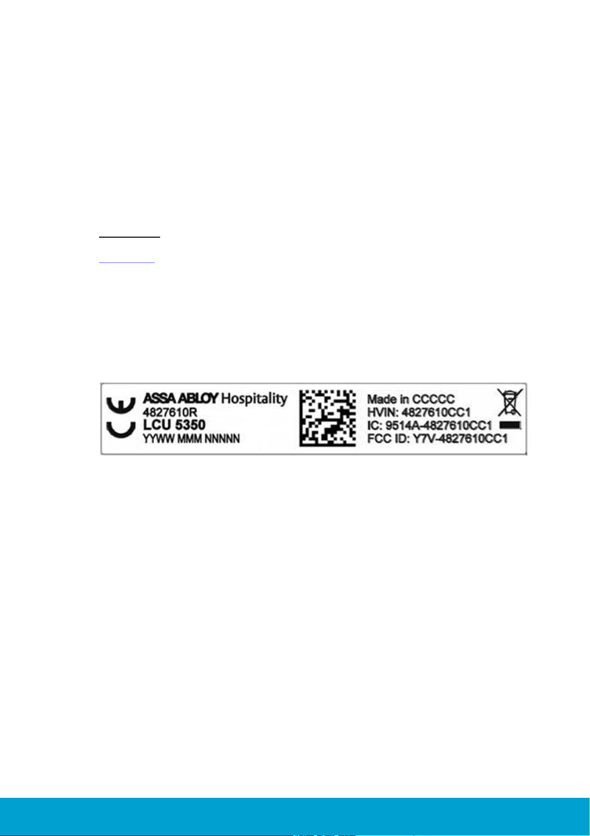
The LCU (lock controller unit) must be labeled to say 'FCC ID: Y7V-4827610CC1'.
IC (Industry Canada) statements
This device complies with Industry Canada licence-exempt RSS standard(s).
Operation is subject to the following two conditions:
(1) this device may not cause interference, and
(2) this device must accept any interference, including interference
that may cause undesired operation of the device.
Le présent appareil est conforme aux CNR d’Industrie Canada applicables aux
appareils radio exempts de licence. L’exploitation est autorisée aux deux
conditions suivantes:
(1) l'appareil ne doit pas produire de brouillage, et
(2) l’utilisateur de l'appareil doit accepter tout brouillage radioélectrique subi,
même si le brouillage est susceptible d’en compromettre le fonctionnement.
The LCU (lock controller unit) is labeled 'IC:9514A-4827610CC1'.
The term "IC" before the equipment certification number only signifies that
the Industry Canada technical specifications were met.
Le terme "IC" devant le numéro de certification signifie seulement que les
specifications techniques Industrie Canada ont été respectées.
ASSA ABLOY Hospitality
6
66 1000 023-2
1. Introduction
The purpose of this document is to give the distributors of VingCard Essence (v2)
locks sufficient information to install and support this type of lock. This manual
contains descriptions and drawings needed for installation, maintenance and
troubleshooting of VingCard Essence (v2). Site survey before installation is also
covered in this document. The VingCard Essence (v2) lock can be used together
with the Visionline system. All dimensions in this manual (where applicable) are
given in mm and inches.
Important: VingCard Essence (v2) can only be installed in non-metallic doors.
Appendix F in this manual contains a summary of the tips, important notes and
cautions from the different sections of this manual. It can be used as an overview
and a reference for different phases of VingCard Essence (v2) installation, from site
survey to completion.
1.1 Lock Controller Unit (LCU) label
Figure 1: Labeling of LCU
ASSA ABLOY Hospitality
7
66 1000 023-2
2. Site survey
Before any order is placed, a site survey must be performed. Details which are
determined during the site survey are e.g.
length of screws, pins and cylinders
opening direction
lock case type
lock case dimensions
striker plate
A thorough and accurate site survey for every door is absolutely essential for the
successful execution of the order and the installation itself. Appendix B contains a
form where site survey notes can be filled in.
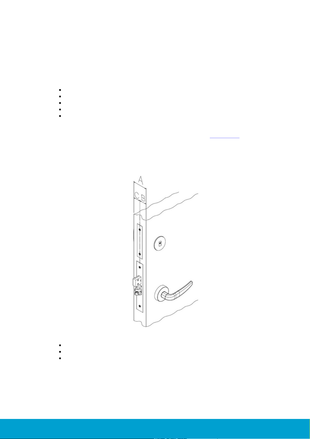
2.1 Door dimensions
The A-dimension is the entire door thickness.
The B-dimension is from the outside door edge to the center of the lock case.
The C-dimension is from the inside door edge to the center of the lock case.
ASSA ABLOY Hospitality
Figure 2: A-, B- and C-dimensions
8
66 1000 023-2
The A-, B- and C-dimensions are important to know when ordering VingCard Essence (v2)
A-Dimension
B-Dimension
38 mm; 1.50"
16 mm; 0.63"
A-Dimension
B-Dimension
129 mm; 5.087"
56 mm; 2.205"
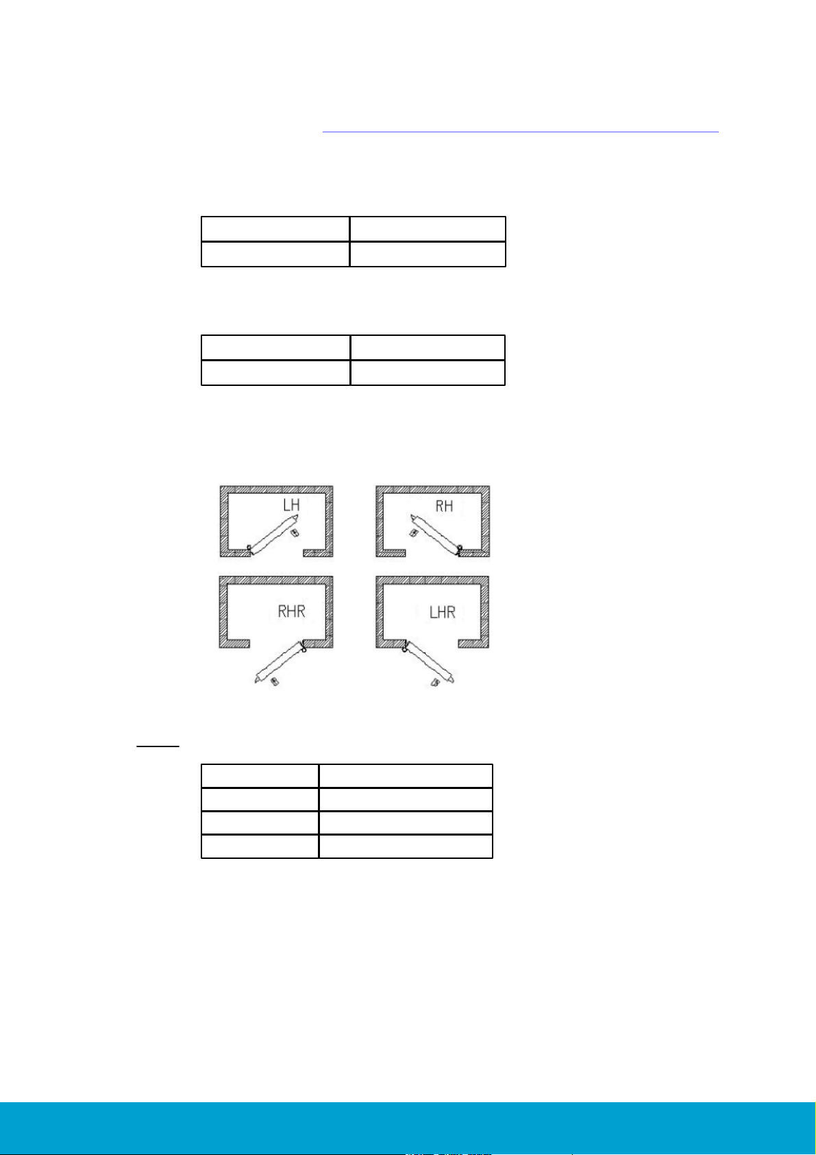
LH
Left handle
RH
Right handle
RHR
Right handle, retract
LHR
Left handle, retract
or certain parts for it. See Appendix A: Part dimensions table for Signature/Essence
for detailed information about length of screws, spindles etc according to the A-, Band C-dimensions.
Minimum door thickness:
Table 1: Minimum door dimensions; applicable for all ANSI types and all EURO types
Maximum door thickness:
Table 2: Maximum door dimensions; applicable for all ANSI types and all EURO types
2.2 Door handing
Figure 3: Door handing; for explanation, see Table 3 below.
Note: Always make sure to have the correct handing for all doors.
Table 3: Explanation of door handing abbreviations
ASSA ABLOY Hospitality
9
66 1000 023-2
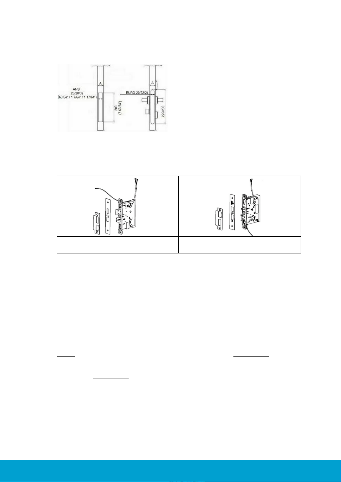
2.3 Type of lock case to be ordered (EURO/ANSI)
Always take the A-dimension in account for the
type of lock case to be ordered. Find out which
standard (ANSI or EURO) that applies for the
property. If the door already has a cut-out,
check if the width and shape of the lock front
fit any of the standard ANSI or EURO lock
front dimensions.
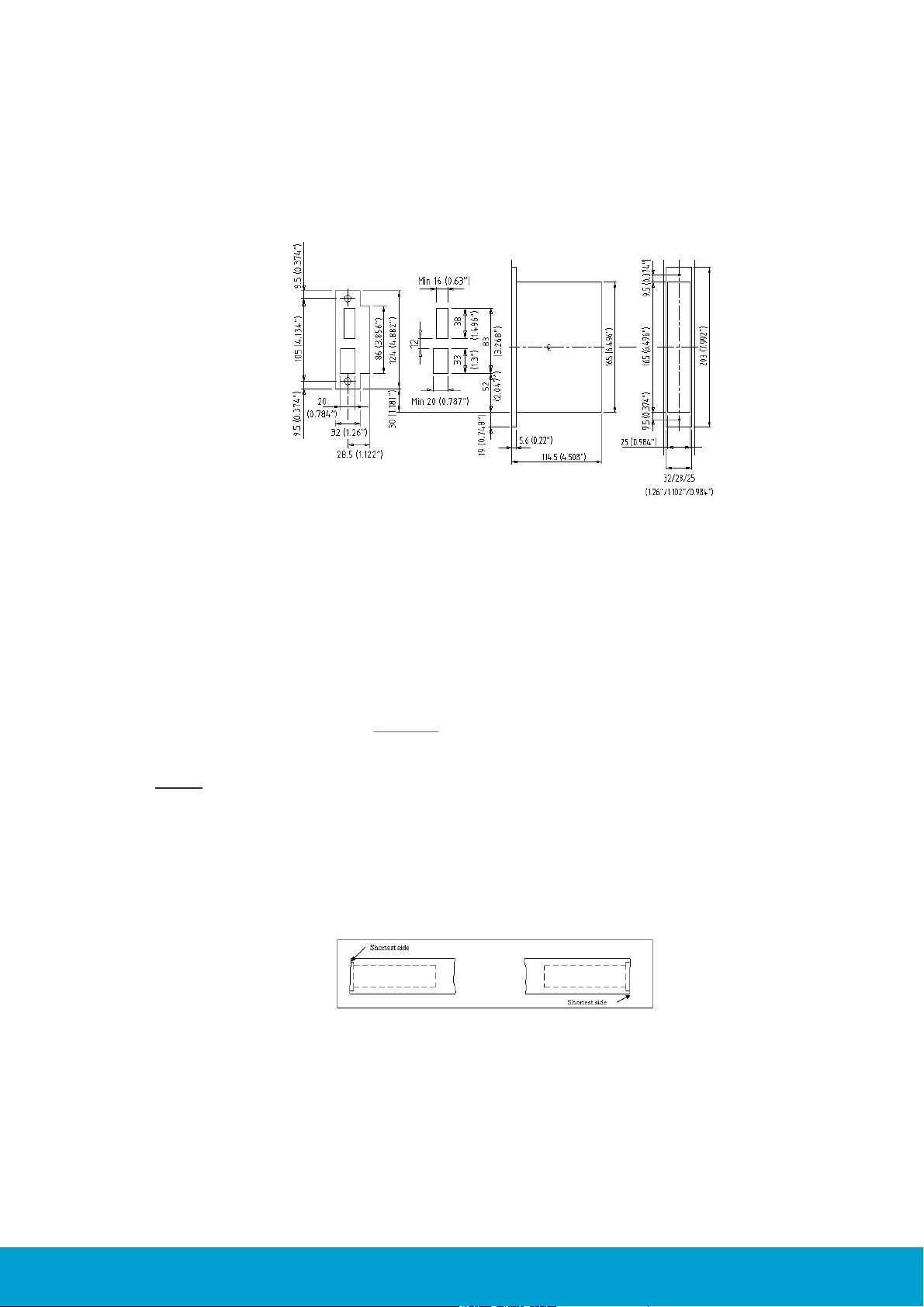
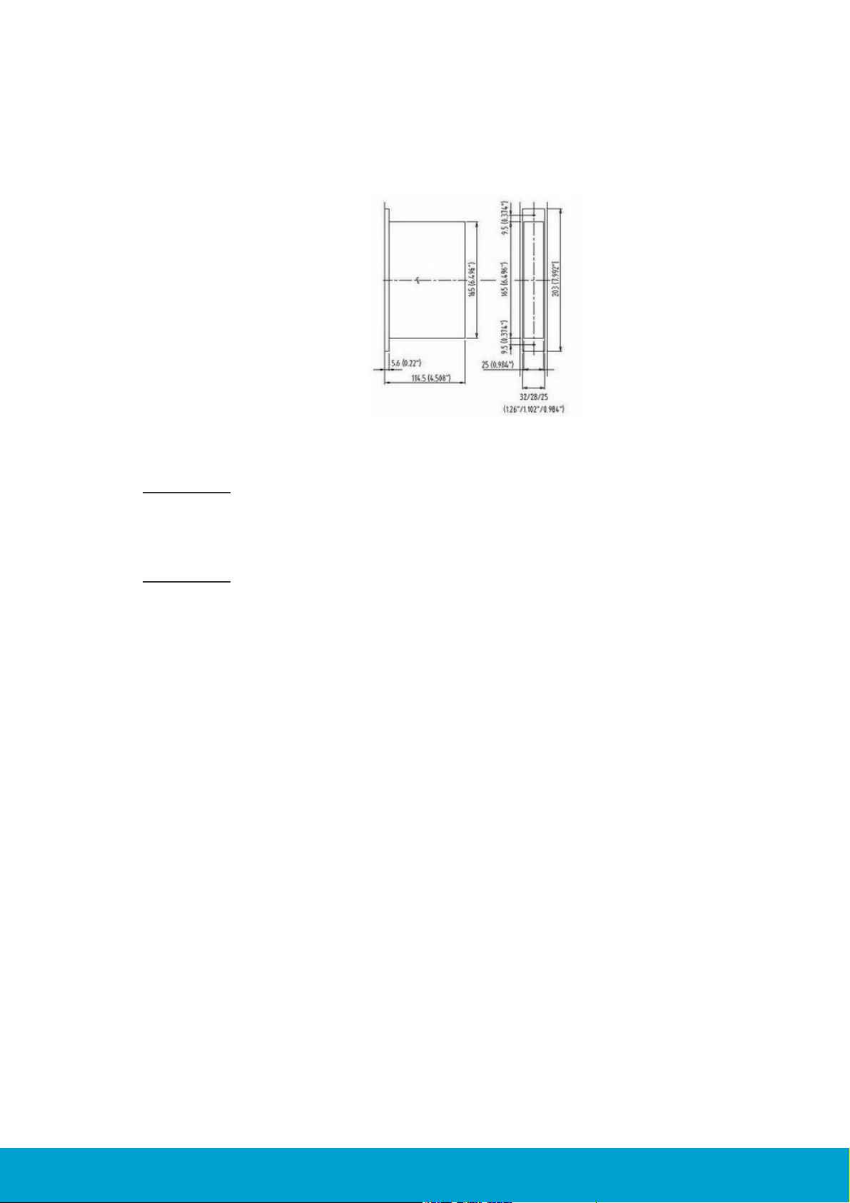
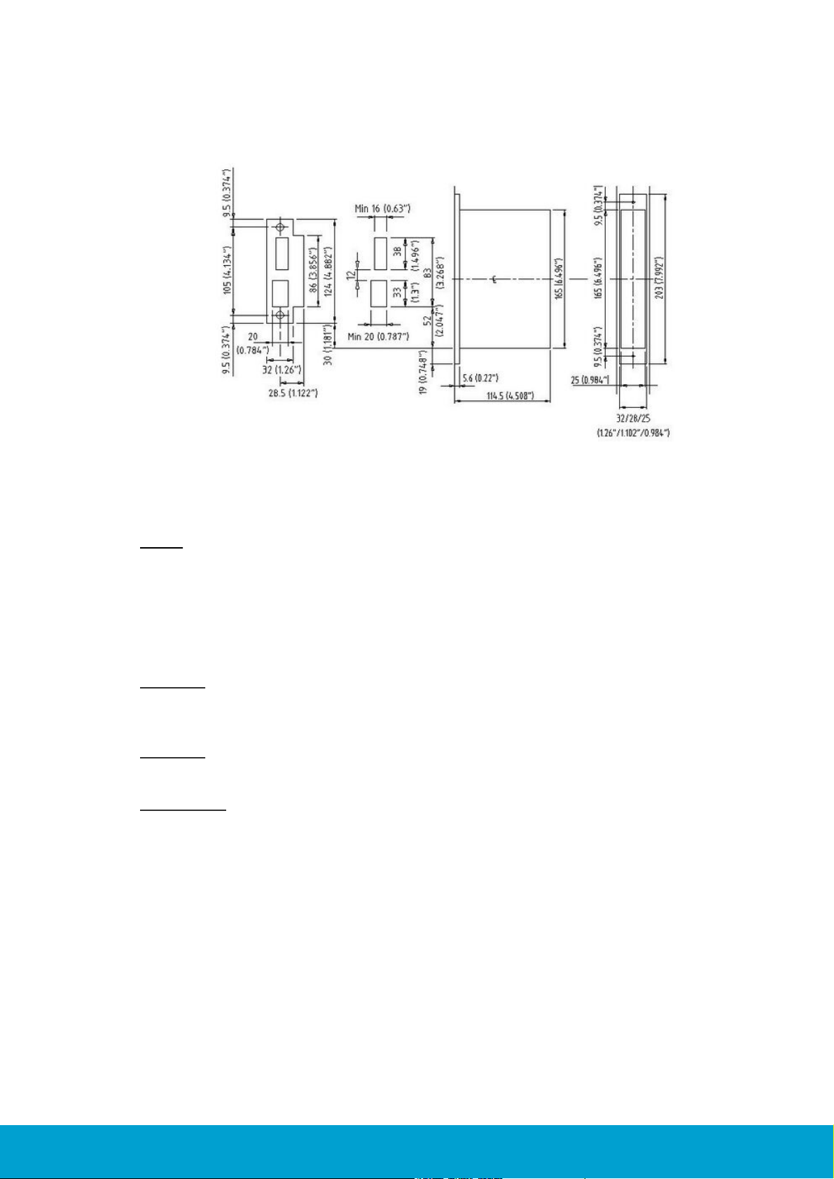
Figure 4: Available heights and widths for ANSI and EURO lock cases
Figure 5: ANSI (DA) lock case;
the Dead-bolt is Above the latch.
Figure 6: ANSI (DB) lock case;
the Dead-bolt is Below the latch.
2.3.1 ANSI lock case orientation
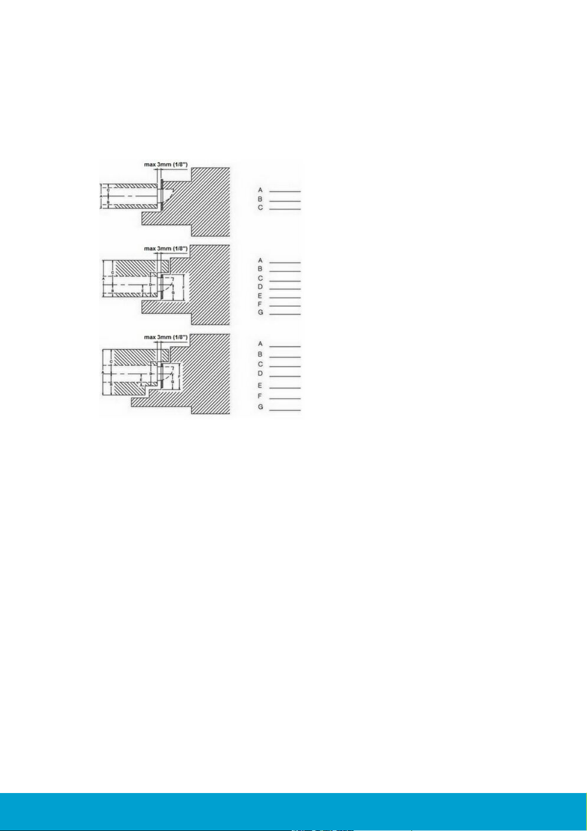
2.4 Dimension requirements
Check the following dimension requirements:
1. The gap between lock front cover and striker plate must not exceed 3 mm; 0.118".
2. For all types of ANSI lock cases, allow at least 25.4 mm (1") depth behind the
striker plate hole for the deadbolt. (Except ANSI AUS = 0 mm and ANSI JPN =
21 mm). Allow 21 mm for EURO lock cases.
3. For all types of ANSI lock cases, allow at least 19 mm (0.748") depth behind the
striker plate hole for the latch. Allow 14 mm for EURO lock cases.
4. Make sure that the lock case, door handles or cylinder does not get in conflict
with i.e. glass windows or ornaments/decor on the door.
Note: See section 3.1 for an overview of available cut-outs. Important: The hole for
the cylinder is optional and is only to be cut out for locks equipped with cylinders and
only from the outside of the door to the center of the lock case; i.e. not through the
entire door. Important: If you are going to install the security cylinder Hydra,
remember to make space for the cylinder fastening clip when making the cut-out
for the lock case.
ASSA ABLOY Hospitality
10
66 1000 023-2
2.5 Check the door frames/striker plates
Figure 8: Beveled doors
Check if you can use ANSI or EURO standard striker plate or if you need to order a
customized striker plate. Check if the door frame is a wooden frame or a steel frame.
This will decide what kind of tools you will need for the installation.
Figure 7: Positioning of ANSI (DA) standard striker plate.
Note the dimension 30 mm (1.181") from the edge
of the lock case to the edge of the striker plate.
Figure 7 above shows the lock case center line (CL); see dot and dash line through the
figure above. The CL is important for the positioning of the lock case, striker plate and
escutcheon onto the doors.
Position of the ANSI standard striker plate:
The striker plate is positioned in the frame so that the bottom of the striker plate
is 30 mm (1.18'') above the bottom of the lock case; see Figure 7. Horizontally,
the B- or C-dimension (see Figure 2) will apply depending on the direction of
the door and the center/rebate orientation.
Note: Be aware if there is any door gasket.
2.6 Beveled doors
If the door is beveled (edge is not at 90º to door), the dimensions should be based
on the shortest side. Standard beveling is 3.2 mm; 1/8".
ASSA ABLOY Hospitality
11
66 1000 023-2
2.7 Rebated doors
Figure 9: Examples of rebated doors
and door frames
When it comes to rebated doors and rebated frames, be extra observant regarding
protrusion for the deadbolt on the frame side. See Figure 9 for examples of rebated
doors and door frames.
ASSA ABLOY Hospitality
12
66 1000 023-2

3. To mortise the door
Description
Online/offline
Document number
ANSI (DA) with cylinder
Online
AN-236
ANSI (DA) with cylinder
Offline
AN-244
ANSI (DA) without cylinder
Online
AN-238
ANSI (DA) without cylinder
Offline
AN-243
ANSI (DB) with cylinder
Online
AN-241
ANSI (DB) without cylinder
Online
AN-239
EURO with cylinder
Online
AN-242
EURO without cylinder
Online
AN-240
Table 4
Before installing the lock in the door, the door and door frame must be mortised
to fit this type of lock. The mortising should be based on the dimensions shown
in the applicable cut-out; see section 3.1 for an overview of available cut-outs.
The position of the lock case (lock case center line) has to be set according to
the ANSI standard and be level from the floor. American Disabilities Act (ADA)
requirements demand a maximum of 1220 mm (48") height to the highest point
of operation.
3.1 Cut-outs
The following cut-outs are available:
ASSA ABLOY Hospitality
13
66 1000 023-2
3.2 To mortise for the lock case
Figure 10: Cut-out for
ANSI (DA) lock case
Determine where the positioning of the lock case center line (CL) shall be, and make
the cut-out according to Figure 10.
Important: The lock front can be delivered with a width of 32 mm (1.26"), 28 mm
(1.102") or 25 mm (0.984"). Make sure that you mortise the door to the correct
dimensions for your lock dimensions. Check the dimensions of the lock before you
start cutting.
Important: If you are going to install the security cylinder Hydra, remember to
make space for the cylinder fastening clip when making the cut-out for the lock case.
3.2.1 Tools needed to make the cut-out for the lock case
Hammer and chisel are needed to make the corners for the lock front.
ASSA ABLOY Hospitality
14
66 1000 023-2
3.3 To mortise for the striker plate
Figure 11: External striker plate dimensions and
cut-out dimensions for ANSI (DA).
Note: Be aware of the dimension 30 mm (1.181'') from the edge of the lock case to
the edge of the striker plate.
Before mortising for the striker plate, make sure to align the side template vertically
and horizontally according to Figure 11. Use the center line (CL) for the lock case as
a reference. Position the striker plate so that the bottom of the striker plate is 30 mm
(1.18") above the bottom of the lock case.
Caution: If the cut-out for the deadbolt is less than 25.4 mm (1") deep, the deadbolt
may not be retracted by use of a metal key in case of an emergency when the door is
double locked (ANSI AUS = 0, ANSI JPN = 21).
Caution: Be aware if there is any door gasket. If so, compensation must be made by
adjusting the horizontal positioning of the striker plate.
Important: If the striker plate is not used (example: steel frame), it is important
that the distance between the latch (lower) cut-out and the deadbolt cut-out must
be 12 mm (0,47") in order for the auxiliary latch to work.
3.3.1 Tools needed to make the cut-out for the striker plate
Use an ordinary drilling machine, hammer and chisel.
ASSA ABLOY Hospitality
15
66 1000 023-2
4. To install the lock
Gothic
ANSI
Straight
Wing
Figure 13: Standard Essence door handles
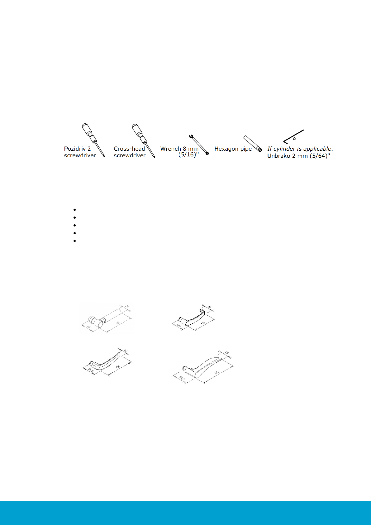
4.1 Necessary tools for the installation
Figure 12: Tools needed for installing the lock;
the Unbrako is only needed if cylinder is applicable
The tools shown in Figure 12 are needed for assembly of the lock:
Pozidriv 2 screwdriver
Cross-head screwdriver
Wrench 8 mm (5/16)''
Hexagon pipe
If cylinder is applicable: Unbrako 2 mm (5/64)''; only used to fasten the
cylinder fastening screw
4.2 Door handle selection
It is possible to choose between a variety of standard door handles and a variety
of door handles from the Designers Collection from Valli & Valli.
ASSA ABLOY Hospitality
16
66 1000 023-2

AC Nonvantuno
GP Novantotto
H123 R8 (Valli &
Valli)
K1160 R8 (Valli & Valli)
MDF Duemiladue
NF Novantotto
Quattro S
Quattro S
S Novanta
Figure 14: Door handles from the Designers Collection from Valli &Valli
ASSA ABLOY Hospitality
17
66 1000 023-2
4.3 Exploded view
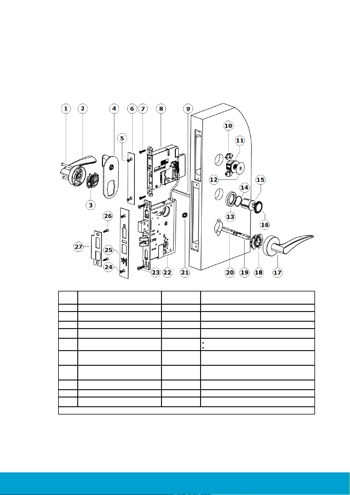
Pos
Description
Available as
single item
Available as kit
1
Screw Signature M5
X
HW kit Essence/Sig 1000-series
2
Handle on inside rose Signature
X
3, 18
Handle retainer*Signature
X
HW kit Essence/Sig 1000-series
4
Escutcheon thumbturn Signature
X
5
Screw, M4x5
X
Front end kit, square, for Essence
Screw kit for ANSI lock case, brass & chrome
6
Front for Essence cassette
X
Front end kit, square, for Essence cassette
7
Screw 4,5 x 22
Front end kit, square, for Essence cassette
8
Essence cassette
X
VingCard Essence (v2) main assembly
9
Thumbturn spindle Signature
X
HW kit Essence/Sig 1000-series
10
Spacer
X
VingCard Essence (v2) main assembly
Table is continued on next page
4.3.1 ANSI (DA)
Figure 15: Components for a VingCard Essence (v2) lock, ANSI (DA) variant with cylinder
ASSA ABLOY Hospitality
18
66 1000 023-2

Pos
Description
Available as
single item
Available as kit
11
LCU 5350
X
VingCard Essence (v2) main assembly
12
Service cover
X
VingCard Essence (v2) main assembly
13
Cylinder rose
X
Cylinder ring kit Signature
14
Spring cylinder rose Signature
X
Cylinder ring kit Signature
15
Cyl 5-lev Std thread front prof R
X
Cyl 5-lev A ADB thread front prof R
X
Cyl 5-lev E ADB thread front prof R
X
16
Cylinder sealing assy
X
Cylinder ring kit Signature [finish] XXmm w/seal
17
Handle on outside rose Signature
X
18
See 3, 18
X
HW kit Essence/Sig 1000-series
19
Spindle handle male Signature
X
Square spindle assy Signature
*)
20
Spindle handle female Signature
X
Square spindle assy Signature
*)
21
Spindle locking clip
X
HW kit Essence/Sig 1000-series
22
Lock case ANSI DA
X
Lock case ANSI DA ADB
X
23
Screw wood, countersunk 5X25 mm
X
Screw kit for ANSI lock case, brass & chrome
24
Screw, M4x5
X
Front end kit, square, for Essence cassette
Screw kit for ANSI lock case, brass & chrome
25
Lock front ANSI
X
Lock front ANSI ADB
X
26
Screw 5,00x12 st 4,8 Zinc color
Screw kit for ANSI lock case, brass & chrome
Screw 5,00x12 st 4,8 Yellow color
Screw kit for ANSI lock case, brass & chrome
Screw, wood, countersunk, 5x25mm,
Metal zinc color
Screw kit for ANSI lock case, brass & chrome
Screw, wood, countersunk, 5x25mm,
Metal yellow color
Screw kit for ANSI lock case, brass & chrome
27
Striker plate ANSI
X
Striker plate ANSI ADB
X
Table 5
*) 'Square spindle assy Signature’ is sold as a separate kit, but is also included in 'HW kit Essence/Sig 1000-series'.
ASSA ABLOY Hospitality
19
66 1000 023-2
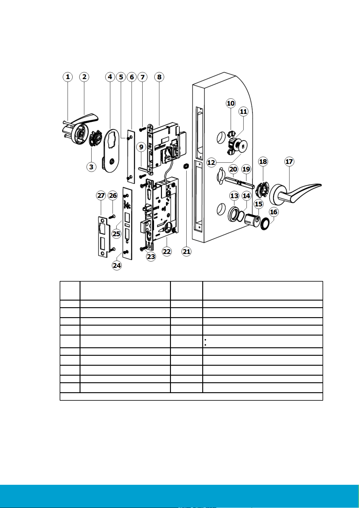
4.3.2 ANSI (DB)
Pos
Description
Available
as
single item
Available as kit
1
Screw Signature M5
X
HW kit Essence/Sig 1000-series
2
Handle on inside rose Signature
X
3, 18
Handle retainer*Signature
X
HW kit Essence/Sig 1000-series
4
Escutcheon thumbturn Signature
X
5
Screw, M4x5
X
Front end kit, square, for Essence
Screw kit for ANSI lock case, brass & chrome
6
Front for Essence cassette
X
Front end kit, square, for Essence cassette
7
Screw 4,5 x 22
Front end kit, square, for Essence cassette
8
Essence cassette
X
VingCard Essence (v2) main assembly
9
Thumbturn spindle Signature
X
HW kit Essence/Sig 1000-series
10
Spacer
X
VingCard Essence (v2) main assembly
Table is continued on next page
Figure 16: Components for a VingCard Essence (v2) lock, ANSI (DB) variant with cylinder
ASSA ABLOY Hospitality
20
66 1000 023-2

Pos
Description
Available
as
single item
Available as kit
11
LCU 5350
X
VingCard Essence (v2) main assembly
12
Service cover
X
VingCard Essence (v2) main assembly
13
Cylinder rose
X
Cylinder ring kit Signature
14
Spring cylinder rose Signature
X
Cylinder ring kit Signature
15
Cyl 5-lev Std thread front prof R
X
Cyl 5-lev A ADB thread front prof R
X
Cyl 5-lev E ADB thread front prof R
X
16
Cylinder sealing assy
X
Cylinder ring kit Signature [finish] XXmm w/seal
17
Handle on outside rose Signature
X
18
See 3, 18
X
HW kit Essence/Sig 1000-series
19
Spindle handle male Signature
X
Square spindle assy Signature
*)
20
Spindle handle female Signature
X
Square spindle assy Signature
*)
21
Spindle locking clip
X
HW kit Essence/Sig 1000-series
22
Lock case ANSI DB
X
Lock case ANSI DB ADB
X
23
Screw wood, countersunk 5X25 mm
X
Screw kit for ANSI lock case, brass & chrome
24
Screw, M4x5
X
Front end kit, square, for Essence cassette
Screw kit for ANSI lock case, brass & chrome
25
Lock front ANSI
X
Lock front ANSI ADB
X
26
Screw 5,00x12 st 4,8 Zinc color
Screw kit for ANSI lock case, brass & chrome
Screw 5,00x12 st 4,8 Yellow color
Screw kit for ANSI lock case, brass & chrome
Screw, wood, countersunk, 5x25mm,
Metal zinc color
Screw kit for ANSI lock case, brass & chrome
Screw, wood, countersunk, 5x25mm,
Metal yellow color
Screw kit for ANSI lock case, brass & chrome
27
Striker plate ANSI
X
Striker plate ANSI ADB
X
Table 6
*) 'Square spindle assy Signature’ is sold as a separate kit, but is also included in 'HW kit Essence/Sig 1000-series'.
ASSA ABLOY Hospitality
21
66 1000 023-2
Loading...