

Page 1
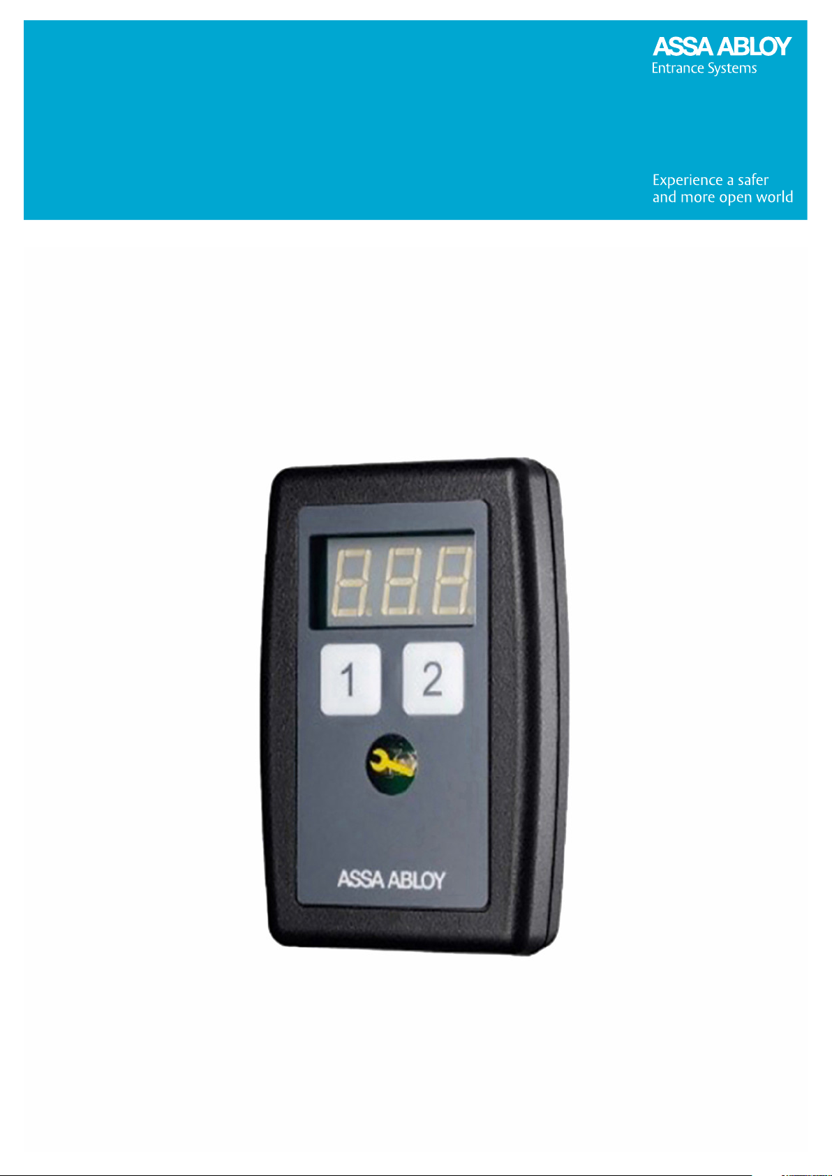
Configuration manual, installation and
service
920-950 Docking
Page 2

Configuration manual, installation and service
920-950 Docking
Copyright and Disclaimer Notice
Although the contents of this publication have been compiled with the greatest possible care, ASSA ABLOY cannot accept
liability for any damage that might arise from errors or omissions in this publication. We also reserve the right to make
appropriate technical modifications/replacements without prior notice.
No rights can be derived from the contents of this document.
Color guides: Color differences may occur due to different printing and publication methods.
ASSA ABLOY as word and logo are trademarks belonging to the ASSA ABLOY Group.
No part of this publication may be copied or published by means of scanning, printing, photocopying, microfilm or any other
process whatsoever without prior permission in writing by ASSA ABLOY.
© ASSA ABLOY 2006-2024.
All rights reserved.
2
Page 3

Configuration manual, installation and service
920-950 Docking
Contents
Copyright and Disclaimer Notice. . . . . . . . . . . . . . . . . . . . . . . . . . . . . . . . . . . . . . . . . . . . . . . . . . . . . . . . . . . . . . . . . 2
Safety instructions. . . . . . . . . . . . . . . . . . . . . . . . . . . . . . . . . . . . . . . . . . . . . . . . . . . . . . . . . . . . . . . . . . . . . . . . . . . 6
1
1.1
General safety instructions. . . . . . . . . . . . . . . . . . . . . . . . . . . . . . . . . . . . . . . . . . . . . . . . . . . . . . . . . . . . . . . . . . . . . . . . . . . . . . . . . . . . . . . . . . . 6
2
Service Tool Buttons. . . . . . . . . . . . . . . . . . . . . . . . . . . . . . . . . . . . . . . . . . . . . . . . . . . . . . . . . . . . . . . . . . . . . . . . . 7
2.1
Button 1 (Left button). . . . . . . . . . . . . . . . . . . . . . . . . . . . . . . . . . . . . . . . . . . . . . . . . . . . . . . . . . . . . . . . . . . . . . . . . . . . . . . . . . . . . . . . . . . . . . . . 7
Button 2 (Right button). . . . . . . . . . . . . . . . . . . . . . . . . . . . . . . . . . . . . . . . . . . . . . . . . . . . . . . . . . . . . . . . . . . . . . . . . . . . . . . . . . . . . . . . . . . . . . 8
2.2
Button 1 and Button 2. . . . . . . . . . . . . . . . . . . . . . . . . . . . . . . . . . . . . . . . . . . . . . . . . . . . . . . . . . . . . . . . . . . . . . . . . . . . . . . . . . . . . . . . . . . . . . . . 8
2.3
Example, Set the limits for Service Interval d07/d08 . . . . . . . . . . . . . . . . . . . . . . . . . . . . . . . . . . . . . . . . . . . . . . . . . . . . . . . . . . . . . . . . . . 9
2.4
3
CDM9 Door Operator. . . . . . . . . . . . . . . . . . . . . . . . . . . . . . . . . . . . . . . . . . . . . . . . . . . . . . . . . . . . . . . . . . . . . . 10
Component denomination. . . . . . . . . . . . . . . . . . . . . . . . . . . . . . . . . . . . . . . . . . . . . . . . . . . . . . . . . . . . . . . . . . . . . . . . . . . . . . . . . . . . . . . . . . 10
3.1
Configuration and error reading, Service tool. . . . . . . . . . . . . . . . . . . . . . . . . . . . . . . . . . . . . . . . . . . . . . . . . . . . . . . . . . . . . . . . . . . . . . . . 13
3.2
Indication of time for service. . . . . . . . . . . . . . . . . . . . . . . . . . . . . . . . . . . . . . . . . . . . . . . . . . . . . . . . . . . . . . . . . . . . . . . . . . . . . . . . . . . . . . . . 15
3.3
Limitations of the displays. . . . . . . . . . . . . . . . . . . . . . . . . . . . . . . . . . . . . . . . . . . . . . . . . . . . . . . . . . . . . . . . . . . . . . . . . . . . . . . . . . . . . . . . . . . 15
3.4
Automatic closing activated. . . . . . . . . . . . . . . . . . . . . . . . . . . . . . . . . . . . . . . . . . . . . . . . . . . . . . . . . . . . . . . . . . . . . . . . . . . . . . . . . . . . . . . . . 15
3.5
Active IoT. . . . . . . . . . . . . . . . . . . . . . . . . . . . . . . . . . . . . . . . . . . . . . . . . . . . . . . . . . . . . . . . . . . . . . . . . . . . . . . . . . . . . . . . . . . . . . . . . . . . . . . . . . . 15
3.6
CDM9 Installation. . . . . . . . . . . . . . . . . . . . . . . . . . . . . . . . . . . . . . . . . . . . . . . . . . . . . . . . . . . . . . . . . . . . . . . . . . . . . . . . . . . . . . . . . . . . . . . . . . . 15
3.7
3.7.1
3.7.2
Torque setting CDM9 - door. . . . . . . . . . . . . . . . . . . . . . . . . . . . . . . . . . . . . . . . . . . . . . . . . . . . . . . . . . . . . . . . . . . . . . . . . . . . . . . . . . . . . . . . . 21
3.8
3.8.1
Setting automatic closing. . . . . . . . . . . . . . . . . . . . . . . . . . . . . . . . . . . . . . . . . . . . . . . . . . . . . . . . . . . . . . . . . . . . . . . . . . . . . . . . . . . . . . . . . . . 22
3.9
Activation of Automatic closing. . . . . . . . . . . . . . . . . . . . . . . . . . . . . . . . . . . . . . . . . . . . . . . . . . . . . . . . . . . . . . . . . . . . . . . . . . . . . . . . . . . . . 22
3.10
Deactivation of Automatic closing. . . . . . . . . . . . . . . . . . . . . . . . . . . . . . . . . . . . . . . . . . . . . . . . . . . . . . . . . . . . . . . . . . . . . . . . . . . . . . . . . . . 23
3.11
DIP-switch-, and trim potentiometers settings. . . . . . . . . . . . . . . . . . . . . . . . . . . . . . . . . . . . . . . . . . . . . . . . . . . . . . . . . . . . . . . . . . . . . . . 23
3.12
Functions in the Door menu, submenu choice [d]. . . . . . . . . . . . . . . . . . . . . . . . . . . . . . . . . . . . . . . . . . . . . . . . . . . . . . . . . . . . . . . . . . . 25
3.13
3.13.1
3.13.2
3.13.3
3.13.4
3.13.5
3.13.6
3.13.7
Electrical troubleshooting. . . . . . . . . . . . . . . . . . . . . . . . . . . . . . . . . . . . . . . . . . . . . . . . . . . . . . . . . . . . . . . . . . . . . . . . . . . . . . . . . . . . . . . . . . . 33
3.14
3.14.1
3.14.2
3.14.3
3.14.4
3.14.5
3.14.6
3.14.7
3.14.8
3.14.9
3.14.10
3.14.11
3.14.12
3.14.13
3.14.14
3.15
Troubleshooting steps. . . . . . . . . . . . . . . . . . . . . . . . . . . . . . . . . . . . . . . . . . . . . . . . . . . . . . . . . . . . . . . . . . . . . . . . . . . . . . . . . . . . . . . . . . . . . . 37
3.15.1
3.15.2
3.15.3
3.15.4
3.15.5
3.15.6
3.15.7
3.15.8
3.15.9
3.15.10
3.15.11
Overhead sectional door (OHSD) controllers. . . . . . . . . . . . . . . . . . . . . . . . . . . . . . . . . . . . . . . . . . . . . . . . . . . . . . . . . . . . . . 15
Folding door (FD) controller. . . . . . . . . . . . . . . . . . . . . . . . . . . . . . . . . . . . . . . . . . . . . . . . . . . . . . . . . . . . . . . . . . . . . . . . . . . . . . . 19
Torque adjustment after installation. . . . . . . . . . . . . . . . . . . . . . . . . . . . . . . . . . . . . . . . . . . . . . . . . . . . . . . . . . . . . . . . . . . . . . . 22
Fire alarm, FIA. . . . . . . . . . . . . . . . . . . . . . . . . . . . . . . . . . . . . . . . . . . . . . . . . . . . . . . . . . . . . . . . . . . . . . . . . . . . . . . . . . . . . . . . . . . . . 29
Error log, d09. . . . . . . . . . . . . . . . . . . . . . . . . . . . . . . . . . . . . . . . . . . . . . . . . . . . . . . . . . . . . . . . . . . . . . . . . . . . . . . . . . . . . . . . . . . . . . 30
Disable up command on lid, d12. . . . . . . . . . . . . . . . . . . . . . . . . . . . . . . . . . . . . . . . . . . . . . . . . . . . . . . . . . . . . . . . . . . . . . . . . . . 30
Override timer for Auto close, d13. . . . . . . . . . . . . . . . . . . . . . . . . . . . . . . . . . . . . . . . . . . . . . . . . . . . . . . . . . . . . . . . . . . . . . . . . 30
Configurable input options, d22-d28. . . . . . . . . . . . . . . . . . . . . . . . . . . . . . . . . . . . . . . . . . . . . . . . . . . . . . . . . . . . . . . . . . . . . . 30
Configurable output options, d29 – d33. . . . . . . . . . . . . . . . . . . . . . . . . . . . . . . . . . . . . . . . . . . . . . . . . . . . . . . . . . . . . . . . . . . 31
Speed area options for up and down, d38 - d44. . . . . . . . . . . . . . . . . . . . . . . . . . . . . . . . . . . . . . . . . . . . . . . . . . . . . . . . . . . . 32
Operator faults. . . . . . . . . . . . . . . . . . . . . . . . . . . . . . . . . . . . . . . . . . . . . . . . . . . . . . . . . . . . . . . . . . . . . . . . . . . . . . . . . . . . . . . . . . . . 33
Disengagement. . . . . . . . . . . . . . . . . . . . . . . . . . . . . . . . . . . . . . . . . . . . . . . . . . . . . . . . . . . . . . . . . . . . . . . . . . . . . . . . . . . . . . . . . . . 33
Safety edge. . . . . . . . . . . . . . . . . . . . . . . . . . . . . . . . . . . . . . . . . . . . . . . . . . . . . . . . . . . . . . . . . . . . . . . . . . . . . . . . . . . . . . . . . . . . . . . . 33
Balancing. . . . . . . . . . . . . . . . . . . . . . . . . . . . . . . . . . . . . . . . . . . . . . . . . . . . . . . . . . . . . . . . . . . . . . . . . . . . . . . . . . . . . . . . . . . . . . . . . . 33
Internal electrical fault. . . . . . . . . . . . . . . . . . . . . . . . . . . . . . . . . . . . . . . . . . . . . . . . . . . . . . . . . . . . . . . . . . . . . . . . . . . . . . . . . . . . . 33
Operator moves in wrong direction. . . . . . . . . . . . . . . . . . . . . . . . . . . . . . . . . . . . . . . . . . . . . . . . . . . . . . . . . . . . . . . . . . . . . . . . 34
Torque guard. . . . . . . . . . . . . . . . . . . . . . . . . . . . . . . . . . . . . . . . . . . . . . . . . . . . . . . . . . . . . . . . . . . . . . . . . . . . . . . . . . . . . . . . . . . . . . 34
Photocell. . . . . . . . . . . . . . . . . . . . . . . . . . . . . . . . . . . . . . . . . . . . . . . . . . . . . . . . . . . . . . . . . . . . . . . . . . . . . . . . . . . . . . . . . . . . . . . . . . 34
Door position reset. . . . . . . . . . . . . . . . . . . . . . . . . . . . . . . . . . . . . . . . . . . . . . . . . . . . . . . . . . . . . . . . . . . . . . . . . . . . . . . . . . . . . . . . 34
Stop circuit. . . . . . . . . . . . . . . . . . . . . . . . . . . . . . . . . . . . . . . . . . . . . . . . . . . . . . . . . . . . . . . . . . . . . . . . . . . . . . . . . . . . . . . . . . . . . . . . 34
E22. . . . . . . . . . . . . . . . . . . . . . . . . . . . . . . . . . . . . . . . . . . . . . . . . . . . . . . . . . . . . . . . . . . . . . . . . . . . . . . . . . . . . . . . . . . . . . . . . . . . . . . . 35
Light curtain activated by snow, rain, or similar (CDM9S only). . . . . . . . . . . . . . . . . . . . . . . . . . . . . . . . . . . . . . . . . . . . . . 35
Problems during installation and operation. . . . . . . . . . . . . . . . . . . . . . . . . . . . . . . . . . . . . . . . . . . . . . . . . . . . . . . . . . . . . . . . 35
Additional equipment faults. . . . . . . . . . . . . . . . . . . . . . . . . . . . . . . . . . . . . . . . . . . . . . . . . . . . . . . . . . . . . . . . . . . . . . . . . . . . . . . 36
Door does not reverse during installation. . . . . . . . . . . . . . . . . . . . . . . . . . . . . . . . . . . . . . . . . . . . . . . . . . . . . . . . . . . . . . . . . . 37
Door does not open. . . . . . . . . . . . . . . . . . . . . . . . . . . . . . . . . . . . . . . . . . . . . . . . . . . . . . . . . . . . . . . . . . . . . . . . . . . . . . . . . . . . . . . 37
Door does not close. . . . . . . . . . . . . . . . . . . . . . . . . . . . . . . . . . . . . . . . . . . . . . . . . . . . . . . . . . . . . . . . . . . . . . . . . . . . . . . . . . . . . . . 38
Hold-to-run, down. . . . . . . . . . . . . . . . . . . . . . . . . . . . . . . . . . . . . . . . . . . . . . . . . . . . . . . . . . . . . . . . . . . . . . . . . . . . . . . . . . . . . . . . 39
Door reverses or stops without obvious obstacle. . . . . . . . . . . . . . . . . . . . . . . . . . . . . . . . . . . . . . . . . . . . . . . . . . . . . . . . . . . 39
Hold-to-run, both directions. . . . . . . . . . . . . . . . . . . . . . . . . . . . . . . . . . . . . . . . . . . . . . . . . . . . . . . . . . . . . . . . . . . . . . . . . . . . . . . 39
Gentle reverse or Refuse to close. . . . . . . . . . . . . . . . . . . . . . . . . . . . . . . . . . . . . . . . . . . . . . . . . . . . . . . . . . . . . . . . . . . . . . . . . . 40
Black out on display (C-processor board) . . . . . . . . . . . . . . . . . . . . . . . . . . . . . . . . . . . . . . . . . . . . . . . . . . . . . . . . . . . . . . . . . . 40
Input X8. . . . . . . . . . . . . . . . . . . . . . . . . . . . . . . . . . . . . . . . . . . . . . . . . . . . . . . . . . . . . . . . . . . . . . . . . . . . . . . . . . . . . . . . . . . . . . . . . . . 41
Warning / traffic lights. . . . . . . . . . . . . . . . . . . . . . . . . . . . . . . . . . . . . . . . . . . . . . . . . . . . . . . . . . . . . . . . . . . . . . . . . . . . . . . . . . . . . 41
Relays on D-Board. . . . . . . . . . . . . . . . . . . . . . . . . . . . . . . . . . . . . . . . . . . . . . . . . . . . . . . . . . . . . . . . . . . . . . . . . . . . . . . . . . . . . . . . . 42
3
Page 4

Configuration manual, installation and service
920-950 Docking
3.15.12
3.15.13
3.15.14
3.15.15
3.15.16
3.15.17
3.15.18
3.16
Indication of errors (E). . . . . . . . . . . . . . . . . . . . . . . . . . . . . . . . . . . . . . . . . . . . . . . . . . . . . . . . . . . . . . . . . . . . . . . . . . . . . . . . . . . . . . . . . . . . . . 46
3.16.1
3.16.2
950 Docking. . . . . . . . . . . . . . . . . . . . . . . . . . . . . . . . . . . . . . . . . . . . . . . . . . . . . . . . . . . . . . . . . . . . . . . . . . . . . . . 51
4
950D Component denomination. . . . . . . . . . . . . . . . . . . . . . . . . . . . . . . . . . . . . . . . . . . . . . . . . . . . . . . . . . . . . . . . . . . . . . . . . . . . . . . . . . . . 51
4.1
Configuration and error reading, 950D leveler, shelter, and door. . . . . . . . . . . . . . . . . . . . . . . . . . . . . . . . . . . . . . . . . . . . . . . . . . . . . 52
4.2
4.2.1
4.2.2
4.2.3
CDM9 - 950D installation procedure. . . . . . . . . . . . . . . . . . . . . . . . . . . . . . . . . . . . . . . . . . . . . . . . . . . . . . . . . . . . . . . . . . . . . . . . . . . . . . . . 54
4.3
4.3.1
4.3.2
Torque setting CDM9 – 950D. . . . . . . . . . . . . . . . . . . . . . . . . . . . . . . . . . . . . . . . . . . . . . . . . . . . . . . . . . . . . . . . . . . . . . . . . . . . . . . . . . . . . . . . 58
4.4
4.4.1
Functions in the Door menu, submenu choice [d] . . . . . . . . . . . . . . . . . . . . . . . . . . . . . . . . . . . . . . . . . . . . . . . . . . . . . . . . . . . . . . . . . . . 59
4.5
Functions in the Leveler menu, submenu choice [L] . . . . . . . . . . . . . . . . . . . . . . . . . . . . . . . . . . . . . . . . . . . . . . . . . . . . . . . . . . . . . . . . . 61
4.6
4.6.1
4.6.2
4.6.3
4.6.4
4.6.5
4.6.6
Functions in the Shelter menu, submenu choice [S]. . . . . . . . . . . . . . . . . . . . . . . . . . . . . . . . . . . . . . . . . . . . . . . . . . . . . . . . . . . . . . . . . . 68
4.7
4.7.1
4.7.2
Service reset 950D . . . . . . . . . . . . . . . . . . . . . . . . . . . . . . . . . . . . . . . . . . . . . . . . . . . . . . . . . . . . . . . . . . . . . . . . . . . . . . . . . . . . . . . . . . . . . . . . . 68
4.8
4.8.1
Troubleshooting steps Control unit. . . . . . . . . . . . . . . . . . . . . . . . . . . . . . . . . . . . . . . . . . . . . . . . . . . . . . . . . . . . . . . . . . . . . . . . . . . . . . . . . . 69
4.9
4.9.1
4.9.2
4.9.3
4.9.4
Troubleshooting steps Door. . . . . . . . . . . . . . . . . . . . . . . . . . . . . . . . . . . . . . . . . . . . . . . . . . . . . . . . . . . . . . . . . . . . . . . . . . . . . . . . . . . . . . . . . 70
4.10
4.10.1
4.10.2
4.10.3
4.10.4
4.10.5
4.11
Troubleshooting steps Leveler. . . . . . . . . . . . . . . . . . . . . . . . . . . . . . . . . . . . . . . . . . . . . . . . . . . . . . . . . . . . . . . . . . . . . . . . . . . . . . . . . . . . . . . 72
4.11.1
4.11.2
4.11.3
4.11.4
4.11.5
4.11.6
4.11.7
4.11.8
4.11.9
4.11.10
4.11.11
4.11.12
4.11.13
4.11.14
4.11.15
4.11.16
4.11.17
4.11.18
Interlocking relay. . . . . . . . . . . . . . . . . . . . . . . . . . . . . . . . . . . . . . . . . . . . . . . . . . . . . . . . . . . . . . . . . . . . . . . . . . . . . . . . . . . . . . . . . . 43
Power on X14. . . . . . . . . . . . . . . . . . . . . . . . . . . . . . . . . . . . . . . . . . . . . . . . . . . . . . . . . . . . . . . . . . . . . . . . . . . . . . . . . . . . . . . . . . . . . 43
Door reverses on downward movement. . . . . . . . . . . . . . . . . . . . . . . . . . . . . . . . . . . . . . . . . . . . . . . . . . . . . . . . . . . . . . . . . . . 43
Door reverses aginst the floor. . . . . . . . . . . . . . . . . . . . . . . . . . . . . . . . . . . . . . . . . . . . . . . . . . . . . . . . . . . . . . . . . . . . . . . . . . . . . . 43
Door stops to operate. . . . . . . . . . . . . . . . . . . . . . . . . . . . . . . . . . . . . . . . . . . . . . . . . . . . . . . . . . . . . . . . . . . . . . . . . . . . . . . . . . . . . 44
Light curtain. . . . . . . . . . . . . . . . . . . . . . . . . . . . . . . . . . . . . . . . . . . . . . . . . . . . . . . . . . . . . . . . . . . . . . . . . . . . . . . . . . . . . . . . . . . . . . . 44
Retractable photocell . . . . . . . . . . . . . . . . . . . . . . . . . . . . . . . . . . . . . . . . . . . . . . . . . . . . . . . . . . . . . . . . . . . . . . . . . . . . . . . . . . . . . 45
Example, Error Log. . . . . . . . . . . . . . . . . . . . . . . . . . . . . . . . . . . . . . . . . . . . . . . . . . . . . . . . . . . . . . . . . . . . . . . . . . . . . . . . . . . . . . . . . 50
Active errors in the priority sequence (example) . . . . . . . . . . . . . . . . . . . . . . . . . . . . . . . . . . . . . . . . . . . . . . . . . . . . . . . . . . . 50
Entering the menu system. . . . . . . . . . . . . . . . . . . . . . . . . . . . . . . . . . . . . . . . . . . . . . . . . . . . . . . . . . . . . . . . . . . . . . . . . . . . . . . . . 53
Indication of time for service. . . . . . . . . . . . . . . . . . . . . . . . . . . . . . . . . . . . . . . . . . . . . . . . . . . . . . . . . . . . . . . . . . . . . . . . . . . . . . 53
Limitations of the display. . . . . . . . . . . . . . . . . . . . . . . . . . . . . . . . . . . . . . . . . . . . . . . . . . . . . . . . . . . . . . . . . . . . . . . . . . . . . . . . . . 54
950 Docking ( 950D) controller. . . . . . . . . . . . . . . . . . . . . . . . . . . . . . . . . . . . . . . . . . . . . . . . . . . . . . . . . . . . . . . . . . . . . . . . . . . . 54
Automatic closing. . . . . . . . . . . . . . . . . . . . . . . . . . . . . . . . . . . . . . . . . . . . . . . . . . . . . . . . . . . . . . . . . . . . . . . . . . . . . . . . . . . . . . . . . 57
Torque adjustment after installation. . . . . . . . . . . . . . . . . . . . . . . . . . . . . . . . . . . . . . . . . . . . . . . . . . . . . . . . . . . . . . . . . . . . . . . 59
Configurable input options,L23-25, L30-31, and L35-36. . . . . . . . . . . . . . . . . . . . . . . . . . . . . . . . . . . . . . . . . . . . . . . . . . . . 64
Configurable output options L26-28 and L32 . . . . . . . . . . . . . . . . . . . . . . . . . . . . . . . . . . . . . . . . . . . . . . . . . . . . . . . . . . . . . . 66
Example, L01 – Error Log. . . . . . . . . . . . . . . . . . . . . . . . . . . . . . . . . . . . . . . . . . . . . . . . . . . . . . . . . . . . . . . . . . . . . . . . . . . . . . . . . . . 67
Example, Error Log Reset. . . . . . . . . . . . . . . . . . . . . . . . . . . . . . . . . . . . . . . . . . . . . . . . . . . . . . . . . . . . . . . . . . . . . . . . . . . . . . . . . . . 67
Safe loading and gap warning (Teledockonly). . . . . . . . . . . . . . . . . . . . . . . . . . . . . . . . . . . . . . . . . . . . . . . . . . . . . . . . . . . . . . 67
Lock/unlock of control unit. . . . . . . . . . . . . . . . . . . . . . . . . . . . . . . . . . . . . . . . . . . . . . . . . . . . . . . . . . . . . . . . . . . . . . . . . . . . . . . . 67
Example, Select summer function. . . . . . . . . . . . . . . . . . . . . . . . . . . . . . . . . . . . . . . . . . . . . . . . . . . . . . . . . . . . . . . . . . . . . . . . . . 68
Example, Select winter function. . . . . . . . . . . . . . . . . . . . . . . . . . . . . . . . . . . . . . . . . . . . . . . . . . . . . . . . . . . . . . . . . . . . . . . . . . . . 68
L20 - Total service reset (Leveler and door). . . . . . . . . . . . . . . . . . . . . . . . . . . . . . . . . . . . . . . . . . . . . . . . . . . . . . . . . . . . . . . . . 68
Display and service LED does not lit. . . . . . . . . . . . . . . . . . . . . . . . . . . . . . . . . . . . . . . . . . . . . . . . . . . . . . . . . . . . . . . . . . . . . . . . 69
Service indicator illuminates. . . . . . . . . . . . . . . . . . . . . . . . . . . . . . . . . . . . . . . . . . . . . . . . . . . . . . . . . . . . . . . . . . . . . . . . . . . . . . . 69
Service indicator flashes. . . . . . . . . . . . . . . . . . . . . . . . . . . . . . . . . . . . . . . . . . . . . . . . . . . . . . . . . . . . . . . . . . . . . . . . . . . . . . . . . . . 69
Display shows a key. . . . . . . . . . . . . . . . . . . . . . . . . . . . . . . . . . . . . . . . . . . . . . . . . . . . . . . . . . . . . . . . . . . . . . . . . . . . . . . . . . . . . . . . 69
Door does not reverse during installation. . . . . . . . . . . . . . . . . . . . . . . . . . . . . . . . . . . . . . . . . . . . . . . . . . . . . . . . . . . . . . . . . . 70
Door neither starts to open nor close. . . . . . . . . . . . . . . . . . . . . . . . . . . . . . . . . . . . . . . . . . . . . . . . . . . . . . . . . . . . . . . . . . . . . . 70
Door does not close when Close/Auto button is pressed. . . . . . . . . . . . . . . . . . . . . . . . . . . . . . . . . . . . . . . . . . . . . . . . . . . 71
Door in Impulse open and hold to run close mode. . . . . . . . . . . . . . . . . . . . . . . . . . . . . . . . . . . . . . . . . . . . . . . . . . . . . . . . . 71
Door reverses when closing. . . . . . . . . . . . . . . . . . . . . . . . . . . . . . . . . . . . . . . . . . . . . . . . . . . . . . . . . . . . . . . . . . . . . . . . . . . . . . . . 72
Platform not rising. . . . . . . . . . . . . . . . . . . . . . . . . . . . . . . . . . . . . . . . . . . . . . . . . . . . . . . . . . . . . . . . . . . . . . . . . . . . . . . . . . . . . . . . . 72
Dock leveler not rising. . . . . . . . . . . . . . . . . . . . . . . . . . . . . . . . . . . . . . . . . . . . . . . . . . . . . . . . . . . . . . . . . . . . . . . . . . . . . . . . . . . . . 73
Platform does not rise to uppermost limit. . . . . . . . . . . . . . . . . . . . . . . . . . . . . . . . . . . . . . . . . . . . . . . . . . . . . . . . . . . . . . . . . . 73
Platform rises intermittently. . . . . . . . . . . . . . . . . . . . . . . . . . . . . . . . . . . . . . . . . . . . . . . . . . . . . . . . . . . . . . . . . . . . . . . . . . . . . . . 73
Platform rises slowly. . . . . . . . . . . . . . . . . . . . . . . . . . . . . . . . . . . . . . . . . . . . . . . . . . . . . . . . . . . . . . . . . . . . . . . . . . . . . . . . . . . . . . . 74
Platform does not lower. . . . . . . . . . . . . . . . . . . . . . . . . . . . . . . . . . . . . . . . . . . . . . . . . . . . . . . . . . . . . . . . . . . . . . . . . . . . . . . . . . . 74
Platform stays in upmost position. . . . . . . . . . . . . . . . . . . . . . . . . . . . . . . . . . . . . . . . . . . . . . . . . . . . . . . . . . . . . . . . . . . . . . . . . . 74
Platform sinks when the lip extends/swings out. . . . . . . . . . . . . . . . . . . . . . . . . . . . . . . . . . . . . . . . . . . . . . . . . . . . . . . . . . . . 74
Platform sinks when the main switch is off/emergency stop actuated. . . . . . . . . . . . . . . . . . . . . . . . . . . . . . . . . . . . . . . 75
Platform does not rise (Swingdock only). . . . . . . . . . . . . . . . . . . . . . . . . . . . . . . . . . . . . . . . . . . . . . . . . . . . . . . . . . . . . . . . . . . 75
Swing lip does not swing in (Swingdock only). . . . . . . . . . . . . . . . . . . . . . . . . . . . . . . . . . . . . . . . . . . . . . . . . . . . . . . . . . . . . . 75
Swing lip does not swing out (Swingdock only). . . . . . . . . . . . . . . . . . . . . . . . . . . . . . . . . . . . . . . . . . . . . . . . . . . . . . . . . . . . 76
Swing lip swings out, platform not in uppermost position (only Swingdock). . . . . . . . . . . . . . . . . . . . . . . . . . . . . . . . 76
Swing lip swings in when platform lowers (Swingdock only). . . . . . . . . . . . . . . . . . . . . . . . . . . . . . . . . . . . . . . . . . . . . . . . 76
Lip does not retract (Teledock only). . . . . . . . . . . . . . . . . . . . . . . . . . . . . . . . . . . . . . . . . . . . . . . . . . . . . . . . . . . . . . . . . . . . . . . . 76
Auto retraction is not working (Teledock only). . . . . . . . . . . . . . . . . . . . . . . . . . . . . . . . . . . . . . . . . . . . . . . . . . . . . . . . . . . . . 77
Platform not rising (CombiDock only). . . . . . . . . . . . . . . . . . . . . . . . . . . . . . . . . . . . . . . . . . . . . . . . . . . . . . . . . . . . . . . . . . . . . 77
Platform rises intermittently (CombiDock only). . . . . . . . . . . . . . . . . . . . . . . . . . . . . . . . . . . . . . . . . . . . . . . . . . . . . . . . . . . . 77
Contents 4
Page 5

Configuration manual, installation and service
920-950 Docking
4.11.19
4.11.20
4.11.21
4.11.22
4.11.23
4.11.24
4.12
Troubleshooting steps Shelter. . . . . . . . . . . . . . . . . . . . . . . . . . . . . . . . . . . . . . . . . . . . . . . . . . . . . . . . . . . . . . . . . . . . . . . . . . . . . . . . . . . . . . . 79
4.12.1
4.12.2
4.12.3
4.12.4
Indication of errors (F). . . . . . . . . . . . . . . . . . . . . . . . . . . . . . . . . . . . . . . . . . . . . . . . . . . . . . . . . . . . . . . . . . . . . . . . . . . . . . . . . . . . . . . . . . . . . . 80
4.13
All lip sections extend (CombiDock only). . . . . . . . . . . . . . . . . . . . . . . . . . . . . . . . . . . . . . . . . . . . . . . . . . . . . . . . . . . . . . . . . . 77
Left and right lip section do not extend (CombiDock only). . . . . . . . . . . . . . . . . . . . . . . . . . . . . . . . . . . . . . . . . . . . . . . . . 78
Lip does not retract (CombiDock only). . . . . . . . . . . . . . . . . . . . . . . . . . . . . . . . . . . . . . . . . . . . . . . . . . . . . . . . . . . . . . . . . . . . . 78
Lip segments in small truck, no weight compensation active (CombiDock only). . . . . . . . . . . . . . . . . . . . . . . . . . . . 78
Platform does not lower, small truck position (CombiDock only). . . . . . . . . . . . . . . . . . . . . . . . . . . . . . . . . . . . . . . . . . . 78
Platform does not lower, big truck position (CombiDock only). . . . . . . . . . . . . . . . . . . . . . . . . . . . . . . . . . . . . . . . . . . . . 78
Dock shelter starts only for a short time. . . . . . . . . . . . . . . . . . . . . . . . . . . . . . . . . . . . . . . . . . . . . . . . . . . . . . . . . . . . . . . . . . . . 79
Dock shelter does not start. . . . . . . . . . . . . . . . . . . . . . . . . . . . . . . . . . . . . . . . . . . . . . . . . . . . . . . . . . . . . . . . . . . . . . . . . . . . . . . . 79
Dock shelter SIR does not switch off, or switch off and on again. . . . . . . . . . . . . . . . . . . . . . . . . . . . . . . . . . . . . . . . . . . . . 79
Dock shelter SIR does not switch on. . . . . . . . . . . . . . . . . . . . . . . . . . . . . . . . . . . . . . . . . . . . . . . . . . . . . . . . . . . . . . . . . . . . . . . 80
Contents 5
Page 6
Configuration manual, installation and service
920-950 Docking
1
1.1
Carefully read the safety instructions and the manual before starting any work. Warning notices refer to dangers to the life and
health of people or to the machine, equipment or the environment. The notices applied directly to the door must be followed
and kept in legible condition.
The description below uses symbols to draw the reader's attention to the various dangers and to provide useful advice.
Safety instructions
General safety instructions
Indicates a potential danger to persons.Take all possible precautions against risks associated with working
with electrical materials, it may have power connected.
Follow exactly; ignoring this advice can cause a fault or a dangerous situation.
Important information.
WARNING!
ESD sensitive components.
This control is equipped with electronic components, which are sensitive to static electricity. The circuit
boards are located in the drive unit and in the control box, in immediate proximity to the connection
blocks.
In order to prevent the components from being destroyed by static electricity during installation or service
work, any staff coming into contact with the circuit board must first discharge their electric energy by
touching a large grounded metal object immediately in the vicinity of the control, immediately before work
commences.
Safety instructions 6
Page 7
Configuration manual, installation and service
920-950 Docking
2
2.1
·
·
·
·
Service Tool Buttons
Never connect/disconnect the Service tool without first disconnecting the power to the Control unit!
Unwanted commands may be activated. Check that automatic closing has not been activated by mistake!
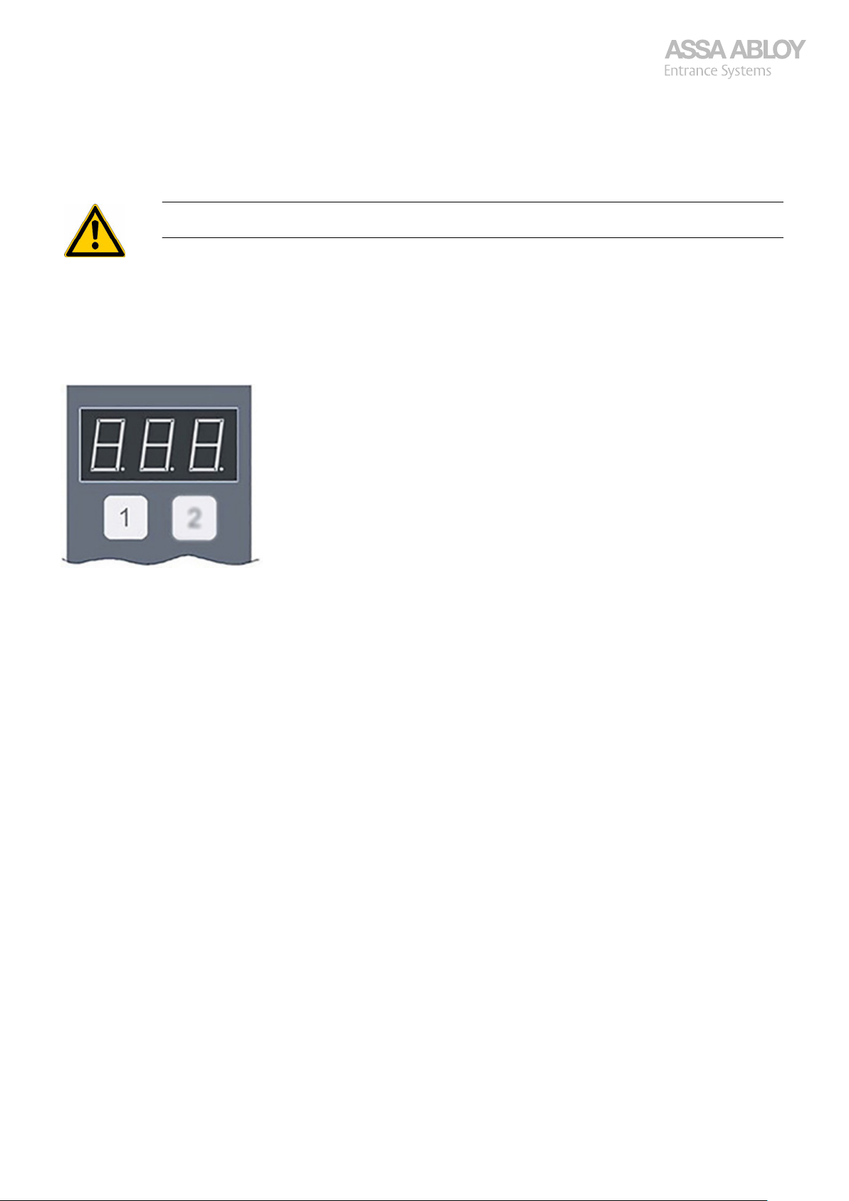
Button 1 (Left button)
Toggles menus, submenus, and values.
Has a repetitive function if pushed and held >1.4 seconds.
Works differently for different menu choices.
BUTTON 1 together with BUTTON 2 stores values.
Service Tool Buttons 7
Page 8
Configuration manual, installation and service
920-950 Docking
2.2
·
·
·
2.3
·
It is possible to disable automatic exit from a menu if no button has been pushed within 30 seconds in menu d0A.
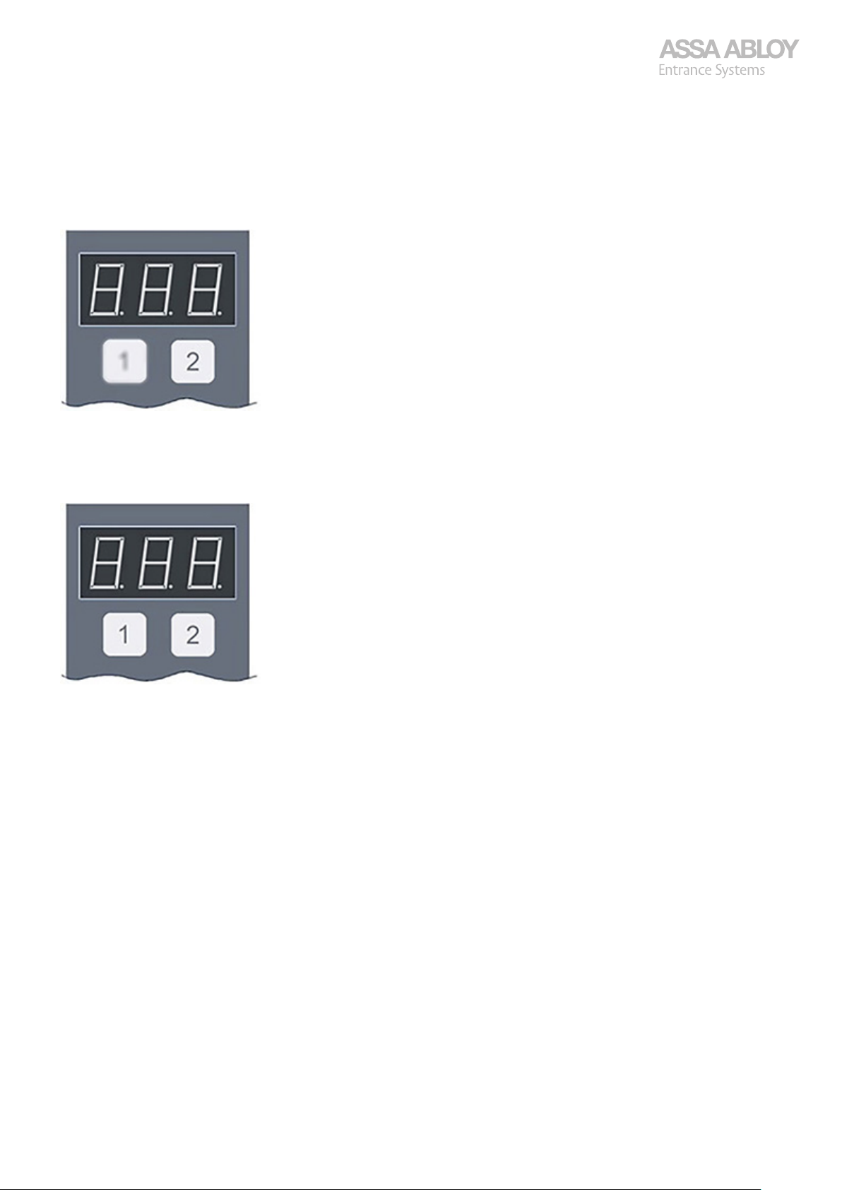
Button 2 (Right button)
Enters and exits menus, sub menus, and settings.
Has no repetitive function.
BUTTON 2 together with BUTTON 1 stores values.
Button 1 and Button 2
Push BUTTON 2 slightly before BUTTON 1 and hold both for a few seconds to SAVE the chosen value in the menu.
Service Tool Buttons 8
Page 9

Configuration manual, installation and service
920-950 Docking
2.4
The display displays the state of the door.
1.
2.
3.
4.
5.
6.
7.
8.
Example, Set the limits for Service Interval d07/d08
Push BUTTON 1, to show menu d01.
Push BUTTON 1 repeatedly until submenu d07 or d08 is displayed.
Push BUTTON 2 to select, e.g. the submenu d07, the value for the stored setting is displayed, e.g. 190, meaning 190 000
cycles.
Push BUTTON 1 to increase the value for the service interval in number of door cycles (x1000).
The value increases by 1 (1000 cycles).
If BUTTON 1 is pushed and held >1.4 seconds, the repetitive function activates.
When the value goes above 999 it starts over from 0 (zero).
Push BUTTON 2 to leave the menu without saving the new value.
Push BUTTON 2 slightly before BUTTON 1 and hold both for a few seconds, to leave the menu and save the value.
Push and hold BUTTON 1 to exit the Service menu.
The display now goes back to normal operation showing the state of the door.
Service Tool Buttons 9
Page 10
Configuration manual, installation and service
920-950 Docking
3
3.1
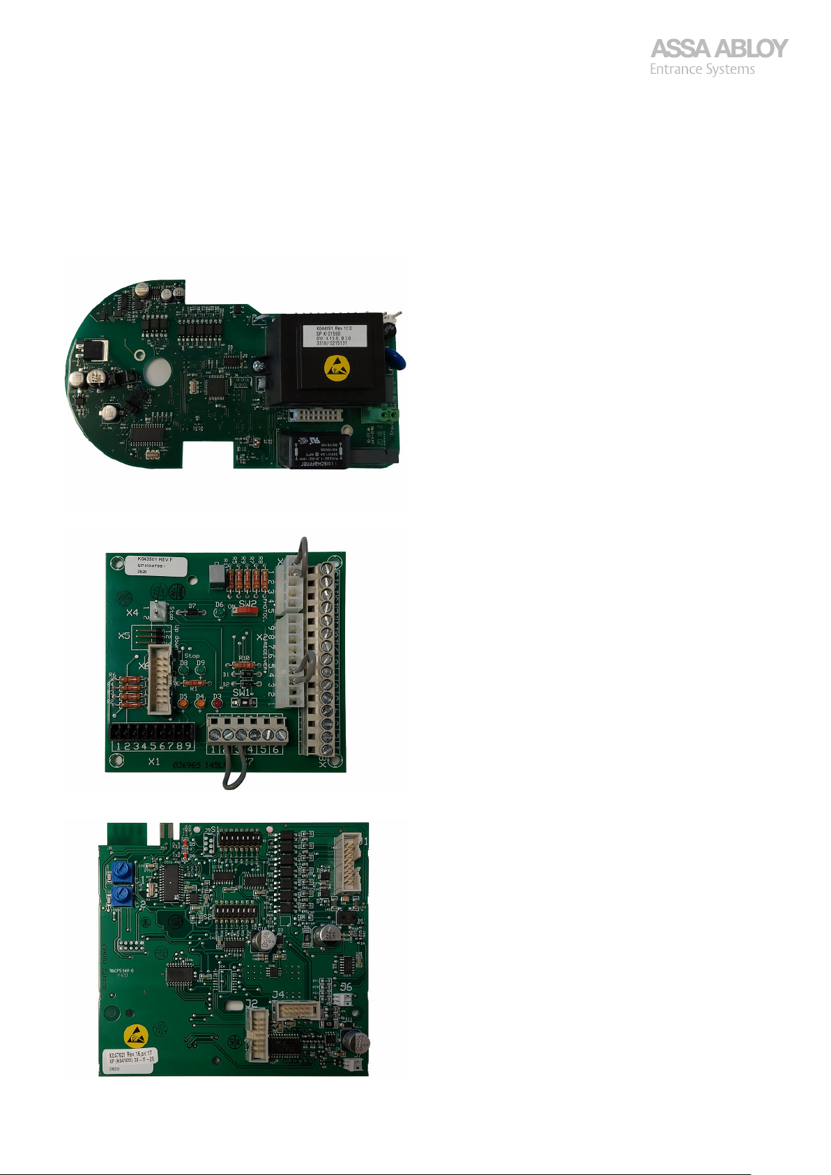
A-processor board
Connector board
CDM9 Door Operator
Component denomination
C-processor board
CDM9 Door Operator 10
Page 11
Configuration manual, installation and service
920-950 Docking
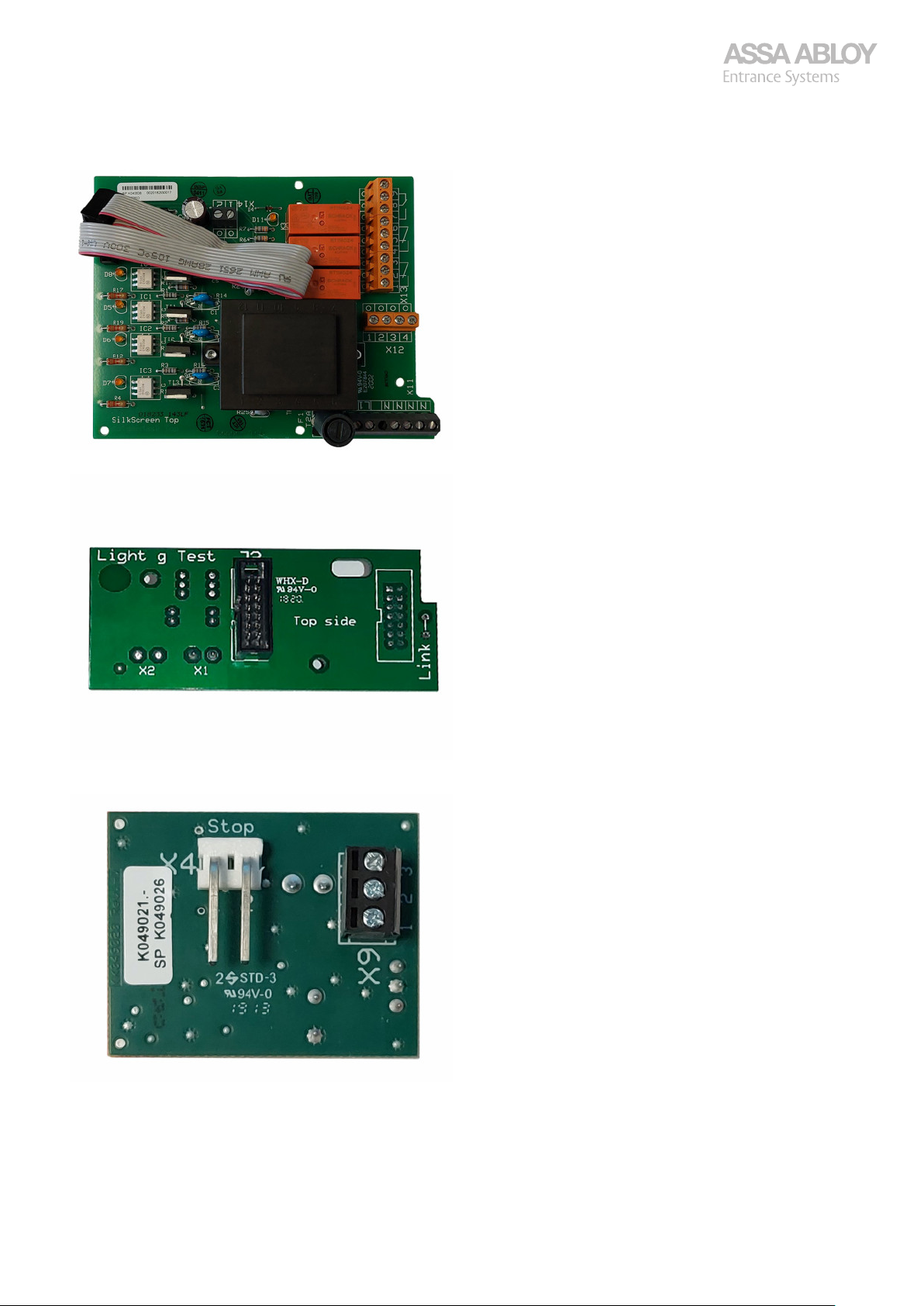
D-board
Light curtain test board
Pass door adapter
CDM9 Door Operator 11
Page 12
Configuration manual, installation and service
920-950 Docking
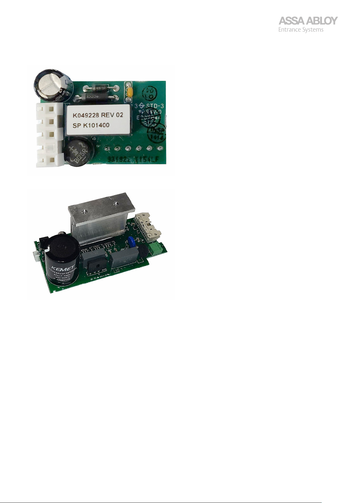
Photocell adapter
PWR-board
CDM9 Door Operator 12
Page 13
Configuration manual, installation and service
920-950 Docking
3.2
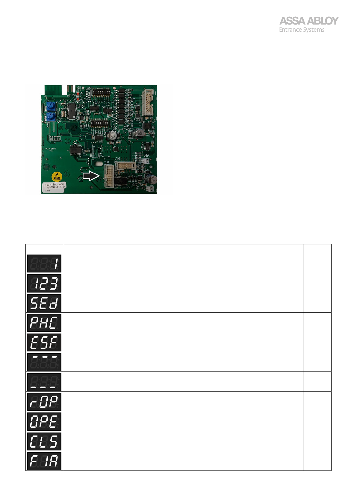
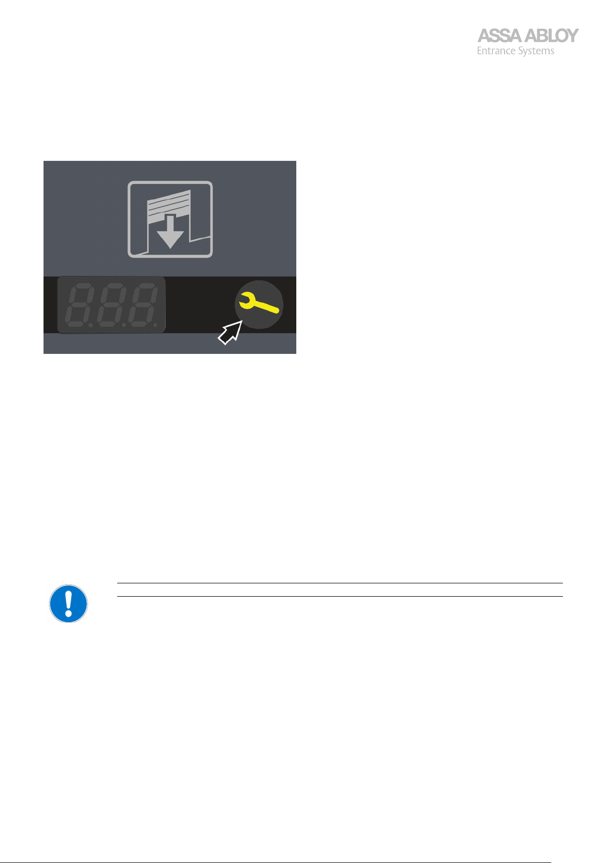
As a tool for certified service and installation staff, the Service tool connects to J2 in the control box.
·
·
·
·
·
Configuration and error reading, Service tool
The current error code is displayed for errors that triggers an error code. If several error codes exist at the same time, the
display alternates between the existing error codes.
The Service tool can display the 15 latest errors from the door.
By default, the state of the door is displayed on the control box and on the display of the Service tool.
A dot in the lower right corner of the display indicates that the automatic closing is activated.
A dot after the first digit of the display indicates an IoT-DMS connection. Flashing light when searching and steady light
when connected.
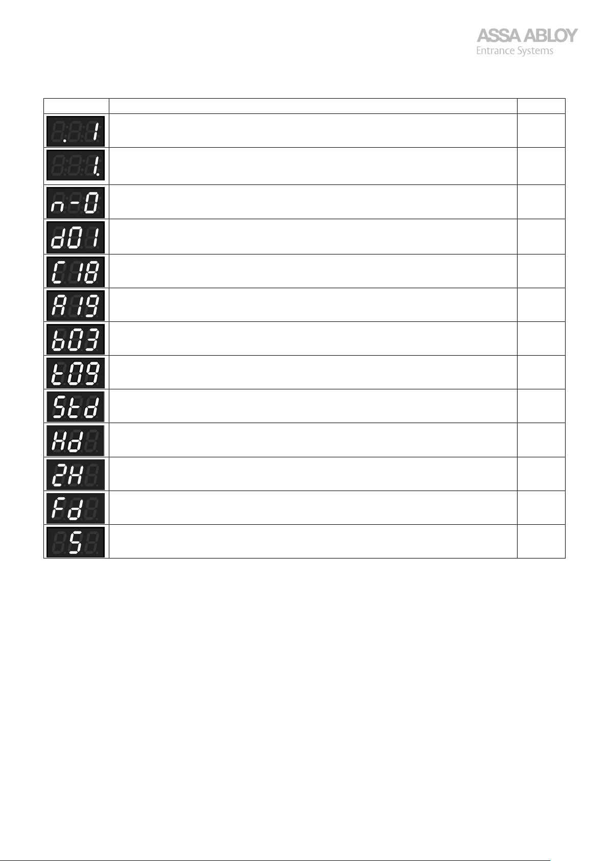
Display Explanation SW
Number of cycles ×1000, displayed static. C0.76
Number of single cycles, displayed alternating between blank - thousands - single cycles. C15
Safety edge active (all variants; PNE, light curtain etc.). C15
Photocell active. C15
Extra safety, X08:5-6 active. C19
Flashing: Door is opening to fully open position.
Static: Door is fully opened.
Flashing: Door is closing to fully closed position.
Static: Door is fully closed.
Door is opening to reduced position. C15
Door is opening to fully open. C15
C20
C20
Door is closing. C15
Fire alarm is active. C15
CDM9 Door Operator 13
Page 14
Configuration manual, installation and service
920-950 Docking
Display Explanation SW
IoT active. C15
Autoclose active.
Flashing dot; automatic closing deactivated because door has been obstructed five times in a row
during automatic closing by the safety edge or over current.
Magnetic lock unlocking. C15
Entered service menu C0.76
C-processor software C15
A-Processor software C15
B-Processor software C15
Torque setting C15/ A10
CDM9 Standard motor installed C18/ A19
CDM9 Heavy duty motor installed C18/ A19
C15
CDM9 2H motor installed C18/ A19
CDM9 Folding door motor installed C18/A19
CDM9 Speed door motor installed C18/A19
CDM9 Door Operator 14
Page 15
Configuration manual, installation and service
920-950 Docking
3.3
Is set Service interval reached, either in operating time or in number of cycles, the SERVICE INDICATOR on the control box lits.
The SERVICE INDICATOR remains lit until the service counters are reset. By setting the service interval limit to 0 the indication
of time to service is disabled.
3.4
The display consists of three digits only. For more than three numbers to show, the display scrolls from right to left.
Example: Total number of cycles 123456, display displays; 123, then 234, then 345 and finally 456.
Indication of time for service
Limitations of the displays
3.5
Activated automatic closing is indicated by a dot in the lower right corner of the display. When the door is about to close
automatically, the number of seconds is displayed, counting down. First for the auto close time, then for the pre-flash warning
lights if they are present. If the right-hand dot is flashing, then the auto close has failed 5 times in a row on safety edge and over
current, and the door has stopped trying. Push "Down" to reset this state (after removing whatever condition that prevented
the automatic closing)
3.6
An active IoT connection is indicated by a dot in the lower left corner of the first digit in the display. If the dot is flashing a
previously established connection with the IoT unit has been lost.
3.7
3.7.1
Always check that:
·
·
·
Automatic closing activated
Active IoT
The unit might need some minutes to connect after a power cycle.
CDM9 Installation
Overhead sectional door (OHSD) controllers
The motor is properly fastened!
The floor is clean under the doors edge!
The buffers are correctly placed and fastened!
CDM9 Door Operator 15
Page 16
Configuration manual, installation and service
920-950 Docking
Motor Types:
Motor type goes together with different settings of the soft ware. Do NOT set a HD mechanical unit for STD
or 2H and so on, type of software MUST always follow the type of mechanical unit!
STD, CDM9 for Over head sectional doors -400 kg 0,25 m/s.
·
2H, CDM9 for Over head sectional doors -250 kg 0,5 m/s.
·
HD, CDM9 for Over head sectional doors 400-800 kg 0,18 m/s.
·
S, CDM9 for High speed over head sectional doors (OH1042S) -300 kg 1 m/s up, 0,7 m/s down.
·
FD, CDM9 for Folding doors 0-400 kg 0.2 m/s.
·
Safety:
HTR, Hold-to-Run, no Safety device!
·
PNE, Pneumatic (Air activated) Rubber edge.
·
RP, Retractable Photo cell, pre-running photocells used together with low thresh hold Pass Door.
·
LG, Light curtain, Light beams across the entire opening normally up to 2.5 m height.
·
Control:
920, Most simple control, no display, and no Safety device.
·
930, Most simple control, no display but with Safety device (only PNE supported).
·
950, Display, Configurable inputs/outputs etc. All safety devices available.
·
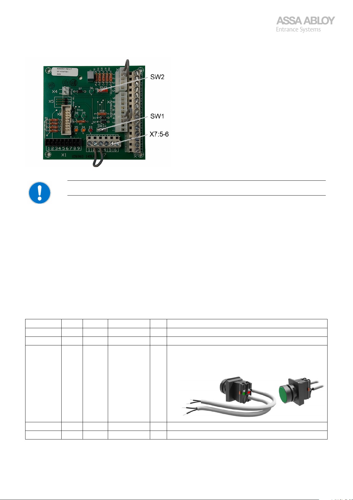
Step Safety Control Motor Type SW Description
1. All All STD, 2H, HD, S All Make sure the door is in closed position.
2. All All STD, 2H, HD, S All Disconnect the power supply.
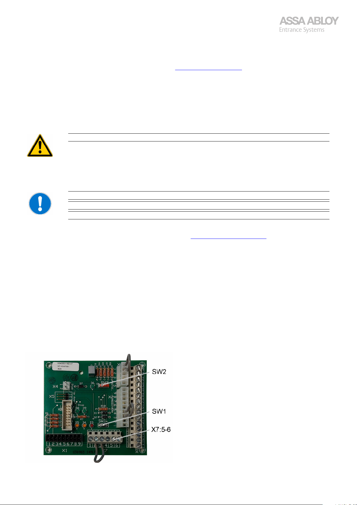
3. Optional HTR,LG920, 950 STD, 2H, HD, S -A16 Connect the temporary installation tool to X7:5-6.
·
·
·
From software version A10 and later use the N.C. contact, for
·
earlier software versions the N.O. contact with diode can be
used.
4. All All STD, 2H, HD, S All Make sure dip switches SW1 and SW2 are in OFF position.
5. All All STD, 2H, HD, S All Pull the green ball to disengage the operator.
CDM9 Door Operator 16
·
·
Page 17
Configuration manual, installation and service
920-950 Docking
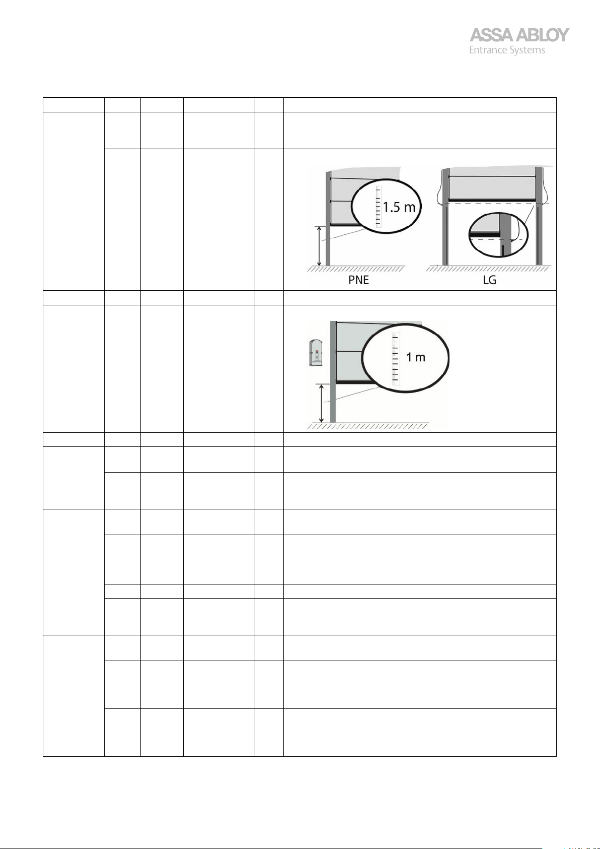
Step Safety Control Motor Type SW Description
6. HTR,
PNE,
RP
LG 950 STD, 2H, HD, S All Manually pull/push the door open to above the LG.
All STD, 2H, HD All Manually pull the door open to 1.5 m above the floor.
·
·
7. All All STD, 2H, HD, S All Pull the red ball to engage the operator.
8. All All STD, 2H, HD, S All Mark the door track 1 m above the floor.
9. All All STD, 2H, HD, S All Reconnect the power supply.
10. All All STD, 2H, HD, S All Pull/Push the door down until the operator gets into gear
All All STD, 2H, HD, S A17- Push the CLOSE-button to jog the motor to engage.
11. Optional
Torque
setting
12. All All STD, S
All All STD, 2H, HD, S All Toggle the dip switch SW2 to ON to enter the torque setting
All All STD, 2H, HD, S All Push and hold the STOP button together with the following op-
All All STD, 2H, HD, S All Release the STOP button to store the torque setting.
All All STD, 2H, HD, S All Toggle the dip switch SW2 to OFF to exit the torque-setting
(2H, HD –A18)
All All 2H A19- Push and hold the STOP button, and at the same time toggle
All All HD A19- Push and hold the STOP button and the CLOSE button, and
·
·
·
·
(click).
·
Only one jog per 3 seconds. Convenient if the door is open
high.
·
mode.
tions:
To increase the torque, push the OPEN button.
·
To decrease the torque, push the CLOSE button.
·
·
·
mode.
Note: Do not switch off the power again!
All Toggle the dip switch SW1 to ON to enable the installation
·
mode of the operator.
·
the dip switch SW1 to ON to enable the 2H installation
mode of the operator.
Release the STOP button.
·
·
at the same time toggle the dip switch SW1 to ON to enable
the HD installation mode of the operator.
Release the STOP and the CLOSE button
·
CDM9 Door Operator 17
Page 18
Configuration manual, installation and service
920-950 Docking
Step Safety Control Motor Type SW Description
13. All All STD, 2H, HD, S All Push the OPEN or the CLOSE button until the bottom edge
14. All All STD, 2H, HD, S A17- Push the STOP button shortly to store the turning direction
15. All All STD, 2H, HD, S -A16 Push the bottom rubber or the installation button to store
16. Optional PNE,RPAll STD, 2H, HD, S All If photocells are installed in rails (connected on X03:1-2):
17. HTR,LGAll STD, 2H, HD, S -A16 Push the installation button to reverse the door as soon as
PNE,
RP,
HTR,
LG
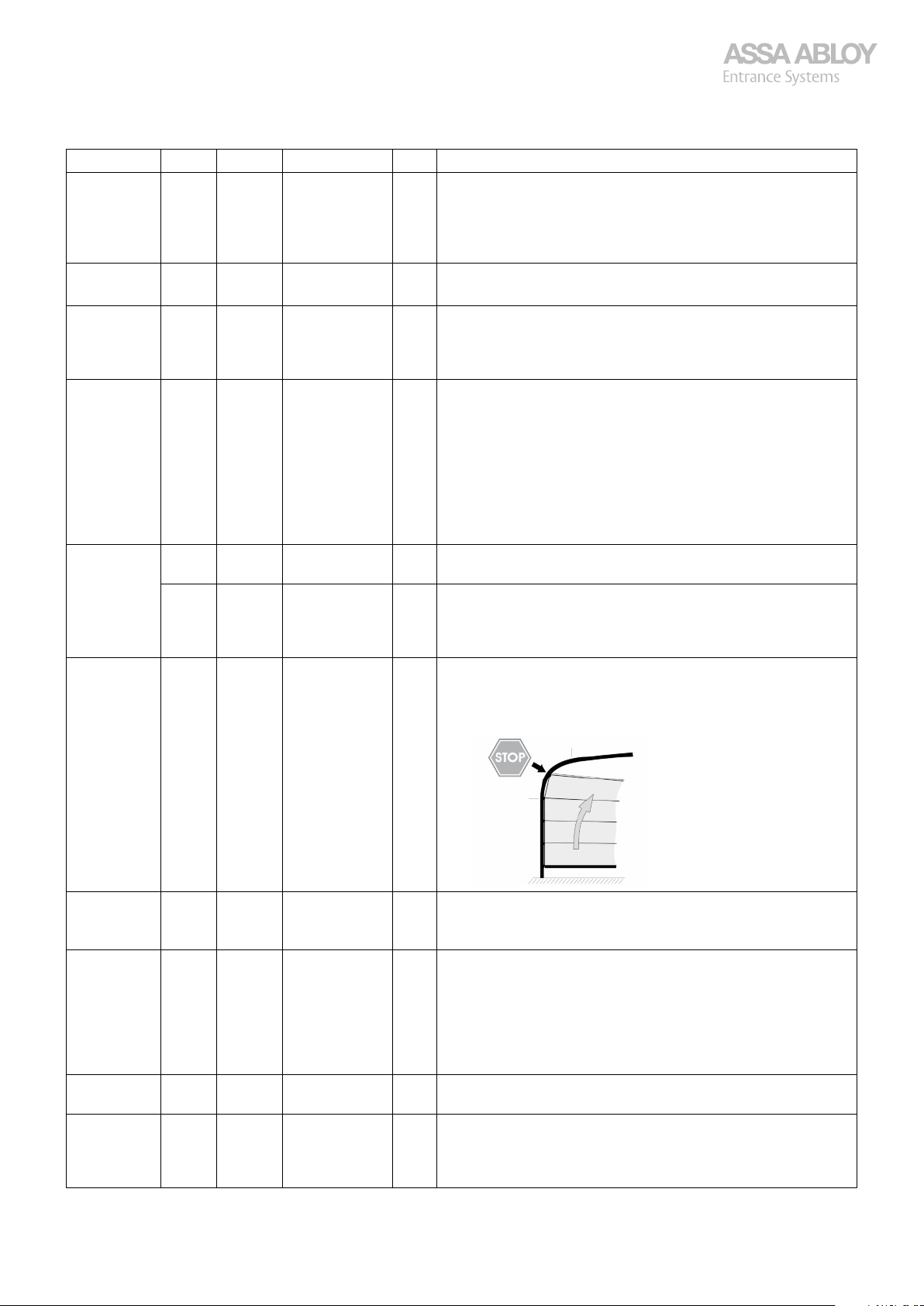
18. All All STD, 2H, HD, S All If the door has track bend:
All STD, 2H, HD, S A17- The door automatically reverses as soon as the door reaches
·
of the door is at the 1 m position, to determine the turning
direction of the operator according to which way it is installed.
Adjust with the OPEN and the CLOSE buttons if necessary.
·
·
of the operator. The door starts to move downwards.
·
the turning direction of the operator.
Make sure that the LEDs D4 and D5 dim for a short period.
·
Push the CLOSE button to close the door.
·
Push the STOP button before the door is blocking the pho-
·
tocell installed in the rails.
Push the CLOSE button again to fully close the door.
·
The system ignores the photocells as a safety pulse below
the installed height. The photocell must be activated on the
way down, towards the floor, otherwise the door stays on
the floor and the installation will not complete.
Note: Max activation height 300 mm from the floor!
·
the door reaches the floor.
·
the floor.
Push the STOP button when the top roller is in the middle of
·
the bend.
Push the OPEN-button again.
·
19. Optional All All STD, 2H, HD, S All If the installation fails due to a too weak motor;
Check the balancing of the door and increase the torque by
·
following step Optional Torque setting in this table.
20. Optional All 950 STD, 2H, HD A15- For hold-to-run Open and/or Close, push and hold STOP
21. All All STD, 2H, HD, S -A16 When door has reached top position, wait 3-4 s then discon-
22. Optional LG All 2H A19- To set full speed down when door has reached top position
For software A19-, confirm that the correct Motor type is displayed when setting SW1 to off (Std, Hd, 2H, S).
CDM9 Door Operator 18
·
within 2 seconds from door has reached open position.
Press OPEN for hold-to-run Open (1 second), and/or CLOSE
·
for hold-to-run Close (1 second), release STOP.
Wait 3-4 seconds before disconnecting eventual Installation
·
tool and set SW1 to OFF.
To deactivate, redo the door installation from the beginning.
·
·
nect eventual Installation tool and set SW1 to OFF.
·
hold the STOP button, and at the same time switch the dip
switch SW1 to OFF.
Lock setting with d45 (recommended).
·
Page 19
Configuration manual, installation and service
920-950 Docking
If E05/E24 is displayed after the installation procedure, redo the procedure from the beginning!
If the error remains, perform the troubleshooting, see section 3.15. Troubleshooting steps on page 37.
3.7.1.1
1.
Make sure the closing door reverses to fully open position when:
·
·
·
2.
Push the OPEN-button to start opening the door and try to stop the door by grabbing the handle to test the overload
safety stop. Max 40 kg lifting allowed. If the door is too strong or weak, adjust the torque and try again.
3.
Make sure all control devices are operational.
4.
Make sure the two yellow LEDs, D4 and D5 (Control PCB) switch off for 2-3 seconds when the door reaches closed
position/ the floor. If the LEDs switch off for no longer than 0.5 second, restart at step 1 to check the safety devices (NOT
applicable for Light Grid).
To regain impulse operation down, make sure to open the door to fully open position to reset the impulse down operation.
If an error occurs, perform an electrical troubleshooting, see section 3.14. Electrical troubleshooting on page 33.
3.7.2
Test and adjustment, OHSD
The safety edge is actuated.
A safety photocell beam is interrupted.
The operator is overloaded (max. excess force is 400 N (40 kg)).
Release the handle before you are lifted by the door, do not attempt to go up with the door.
If LEDs D8 and D9 on the Connector board are lit, the stop circuit is ok.
A power cycle does not affect the programmed installation and settings.
After a power cycle the first closing cycle only works in hold-to-run mode.
Folding door (FD) controller
Follow the instructions to program the CDM9 FD with 950 FD control unit.
Always check that:
The motor is properly fastened!
·
The floor is clean under the doors edge!
·
The limit switch is correctly placed and fastened!
·
The cremone bolt switch(-es) are connected to avoid damages.
·
That no one is trapped between the door panels or at the wall at a fully open door.
·
If an 8k2 magnetic passdoor switch is installed, disconnect the pass door switch PCB and connect the stop in the lid
·
directly.
If LED’s D8 and D9 on the manoeuvering PCB are lit, the stop circuit is ok. At fully open door only D9 is lit if there is a limit
switch for fully open door (standard).
Once the basic installation is completed, make sure to reconnect the pass door switch PCB. Observe that only D9 is lit, D8
is never lit.
Motor Types:
CDM9 Door Operator 19
Page 20
Configuration manual, installation and service
920-950 Docking
FD, CDM9 for Folding Doors 0-400 kg 0,2 m/s.
·
Safety:
PNE, Pneumatic (Air activated) Rubber edge.
·
Control:
950 FD, Display, Configurable Inputs/Outputs etc.
·
Step Safety Control Motor Type SW Description
1. PNE All FD All Put the door in intermediate position.
2. PNE All FD All Disconnect the power supply.
3. PNE All FD All Make sure the dip switches SW1 and SW2 are in OFF posi-
4. PNE All FD All Reconnect the power supply.
5. PNE All FD All Check that the safety device is connected and is operational.
6. Optional
Torque
setting
7. PNE All FD All Toggle dip switch SW1 to ON to enable the installation
8. PNE All FD All Set the Torque setting switch SW2 to ON-position
9. PNE All FD All Use the OPEN/CLOSE buttons to move the door to open po-
10. PNE All FD All Push and hold the CLOSE button. The door moves by hold-
11. PNE All FD All Is the door in the correct position; push the STOP button,
12. PNE All FD All Is the door in the correct position; push the STOP button,
PNE All FD All Toggle the dip switch SW2 to ON to enter the torque setting
PNE All FD All Push and hold the STOP-button together with the following op-
PNE All FD All Release the STOP button to store the torque setting.
PNE All FD All Toggle the dip switch SW2 to OFF to exit the torque-setting
·
·
·
tion.
·
·
The LEDs D4 and D5 switch off when the safety edge(s)
·
is/are activated. There are two edges, one for each LED (D4/
D5).
·
mode.
tions:
To increase the torque, push the OPEN button.
·
To decrease the torque, push the CLOSE button.
·
·
·
mode.
Note: Do not switch off the power again!
·
mode of the operator.
·
·
sition by hold-to-run, all the way to the open position. The
door will hit its open position at full speed.
Note: On doors with limit switch for fully open door, D8 will
switch off.
·
to-run operation into closed position.
When the door leafs are in extended/closed position and
·
parallel with the track, release the CLOSE button (fine adjust
by the OPEN/CLOSE buttons) and then push the STOP button to verify fully closed door.
Note: On Bi-folded doors, both safety edges must activate!
The door opens to a position for the start of the slow speed
area when closing and stops.
·
otherwise fine adjust by the OPEN/CLOSE buttons and push
the STOP button.
The door opens to a position for the start of the slow speed
·
area when opening and stops.
·
otherwise fine adjust by the OPEN/CLOSE buttons and push
the STOP button. The door opens to its open position.
On doors with limit switch for fully open door, D8 will switch
·
off.
CDM9 Door Operator 20
Page 21
Configuration manual, installation and service
920-950 Docking
Step Safety Control Motor Type SW Description
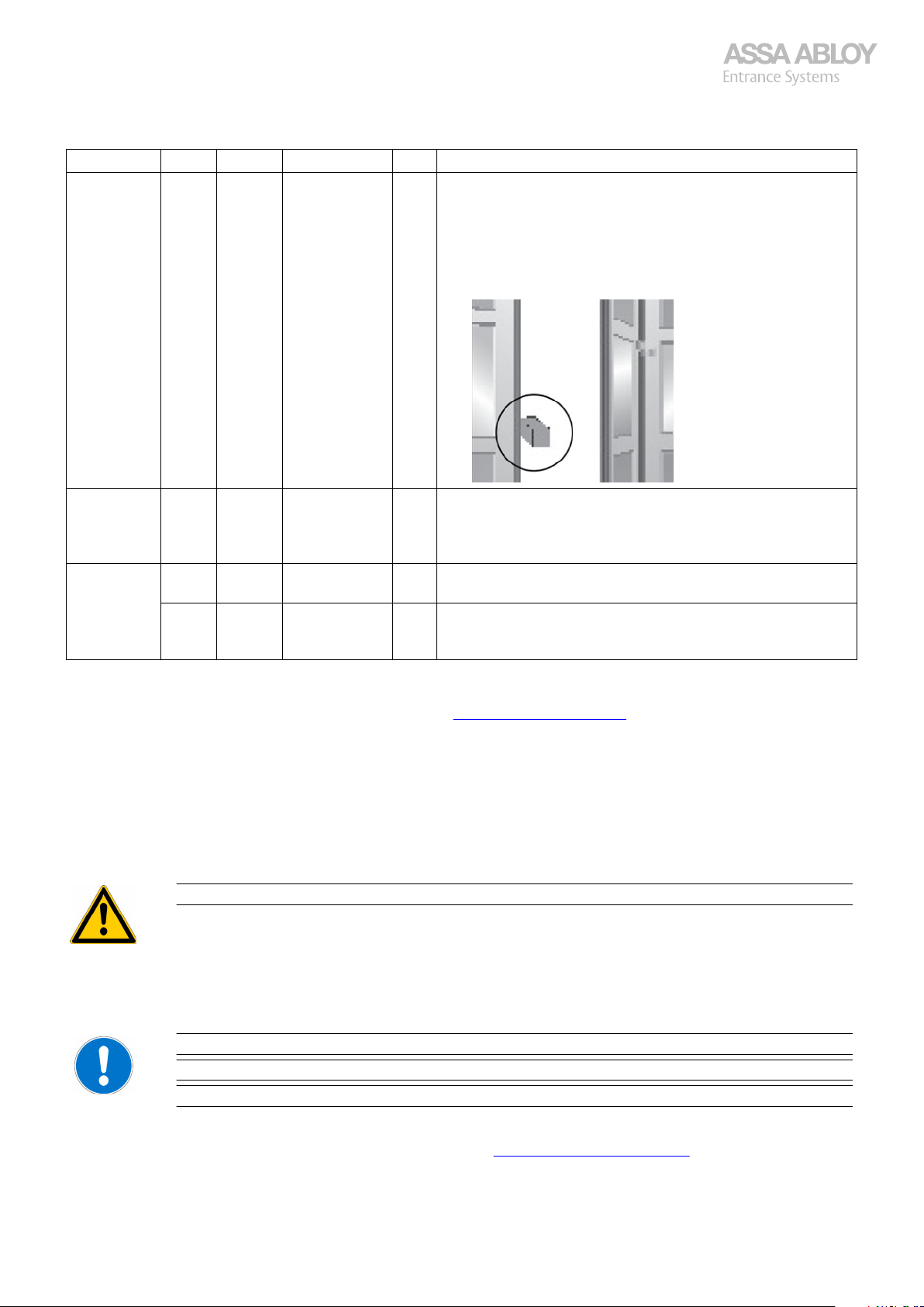
13. PNE All FD All Position the installation block between the doors leafs at
·
about 1 m high.
Push the CLOSE button (impulse operation).The door closes
·
and reverses against the installation block.
Note: On Bi-folded doors, both safety edges must activate!
D4 and D5 dims shortly. The door opens to fully open position.
In case of
failure
14. PNE All FD All Switch OFF the Torque setting switch SW2, and the Installa-
If E05/E24 is displayed after the installation procedure, redo the procedure from the beginning!
If the error remains, perform the troubleshooting, see section 3.15. Troubleshooting steps on page 37.
3.7.2.1
1.
Make sure the closing door reverses to fully open position when:
·
·
·
2.
Push the OPEN-button to start opening the door and try to stop the door by grabbing the handle to test the overload
safety stop. Max 40 kg pressure allowed. If the door is too strong or weak, adjust the torque and try again.
PNE All FD All If the installation fails due to a too weak motor:
Check how the door is running and then increase the torque
·
by following step Optional: Torque Setting after Step 5 in
this table.
·
tion switch SW1.
PNE All FD A19-
C18-
Switch OFF the Torque setting switch SW2, and the Installa-
·
tion switch SW1.
Verify that Fd is displayed.
·
Test and adjustment, FD
The safety edge is actuated.
A safety photocell beam is interrupted.
The operator is overloaded (max. excess force is 400 N (40 kg)).
Do not get squeezed!
3.
Make sure all control devices are operational.
4.
Make sure the two yellow LEDs, D4 and D5 (Control PCB) switch off for 2-3 seconds when the door reaches closed
position/ the floor. If the LEDs switch off for no longer than 0.5 second, restart at step 1 to check the safety devices (NOT
applicable for Light Grid).
If LEDs D8 and D9 on the Connector board are lit, the stop circuit is ok.
A power cycle does not affect the programmed installation and settings.
After a power cycle the first closing cycle only works in hold-to-run mode.
To regain impulse operation down, make sure to open the door to fully open position to reset the impulse down operation.
If an error occurs, perform an electrical troubleshooting, see section 3.14. Electrical troubleshooting on page 33.
3.8
The torque setting is available in 15 steps. Default factory setting is 9.
CDM9 Door Operator 21
Torque setting CDM9 - door
Page 22
Configuration manual, installation and service
920-950 Docking
On 950-control unit, the torque setting is displayed as t09.
On 920 and 930 control units, button presses must be manually counted.
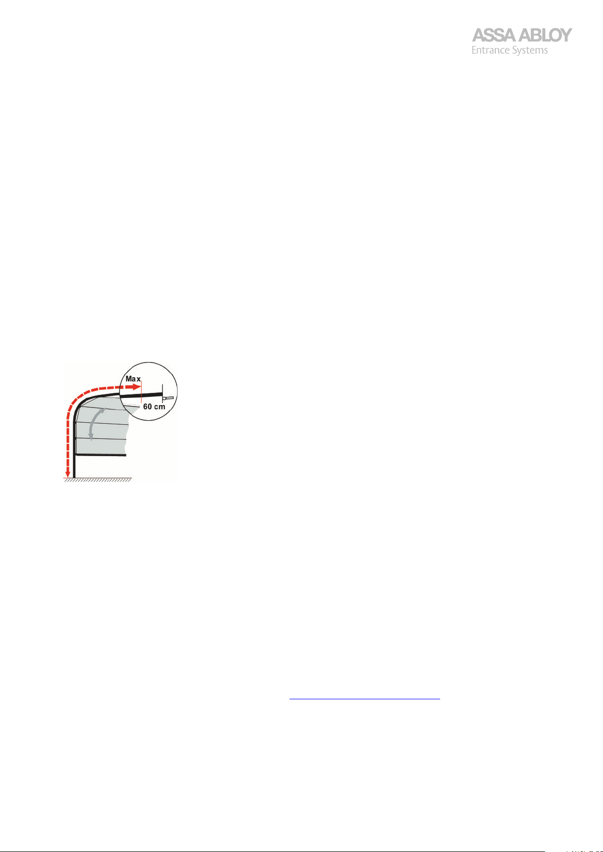
The ideal torque setting is as low as possible for safety reasons, so that the door does not forcibly open or close when
obstructed by people or objects. Max. excess force is 400 N (40 kg).
3.8.1
Only applicable for ECS 930-950, NOT applicable for ECS 920.
Stop the door in an half open position
1.
Set SW2 in the ON position.
2.
Make sure that SW1 is in the OFF position!
3.
Press and hold the Stop button together with the following options:
4.
·
·
Release the stop button.
5.
The new torque value is now stored.
6.
Run the door by impulse operation to a fully open position.
7.
Run the door by impulse operation down.
8.
The door reverses against the floor, runs up and stops with low speed against the buffers.
Push CLOSE-button to make sure learn was successful.
9.
Set the dip switch SW2 in the OFF position.
10.
The door is now ready for operation.
To evaluate the adjusted torque, operate the door within illustrated area.
11.
Torque adjustment after installation
To increase the torque, press the OPEN button
To decrease the torque, press the CLOSE button
3.9
1.
2.
3.
4.
5.
3.10
1.
2.
Setting automatic closing
Toggle dip switch SW2 to ON. Turn potentiometer T1 to adjust the delay time before the flashing signal. The scale ranges from 1 to 80 seconds. When turning T1 the delay time is visible in the digital display. Note! Visualisation in the display only works with SW C14- . If dip switch S2:7 is ON, T1 = 1 - 900 seconds. Turn potentiometer T2 to adjust the duration of the flashing signal before closing. The scale ranges from 1 to 32 seconds.When turning T2 the signal duration time is visible in the digital display. Note! Visualisation in the display only works with SW C14- . Total automatic closing time = T1+T2_. Toggle dip switch SW2 to OFF. Note! Turning dip switch SW 2 or dip switch SW 1 on will deactivate automatic closing, needs to be activated again! Will not be deactivated for SW C16-. Proceed to Activation of Automatic closing, see section 3.10. Activation of Automatic closing on page 22. Note! If during the automatic closing countdown a down command is given from the control unit, the door will close immediately.
Activation of Automatic closing
Press the Up or Down button to operate the door to an intermediate position.
Press and hold the Stop button.
CDM9 Door Operator 22
Page 23
Configuration manual, installation and service
920-950 Docking
3.
Press and hold the Up and Down buttons for at least 6 seconds.
A small dot appears in the lower right corner of the digital display when the buttons are released.
4.
Operate the door to the fully open position and make sure that it starts the closing action after the set time.
Note!
Automatic closing will deactivate after five closing attempts without door movement, e.g. activated spring break device
(SBD), or after the the door has reversed on the safety edge five times in a row (NOT valid for light curtain safety).
A flashing dot appears in the lower right corner of the display as of software A15 and C15 if the automatic closing is
temporarily deactivated. Automatic closing will be reactivated once the Down button is pressed on the control unit.
Automatic closing also works from reduced opening position, safety photocell must be present.
If up/ stop/ open function/ open outside/ open inside/ additional safety/ safety edge/ safety photocell are activated during
the closing/flashing time countdown, the countdown will restart from the beginning.
3.11
1.
2.
3.
3.12
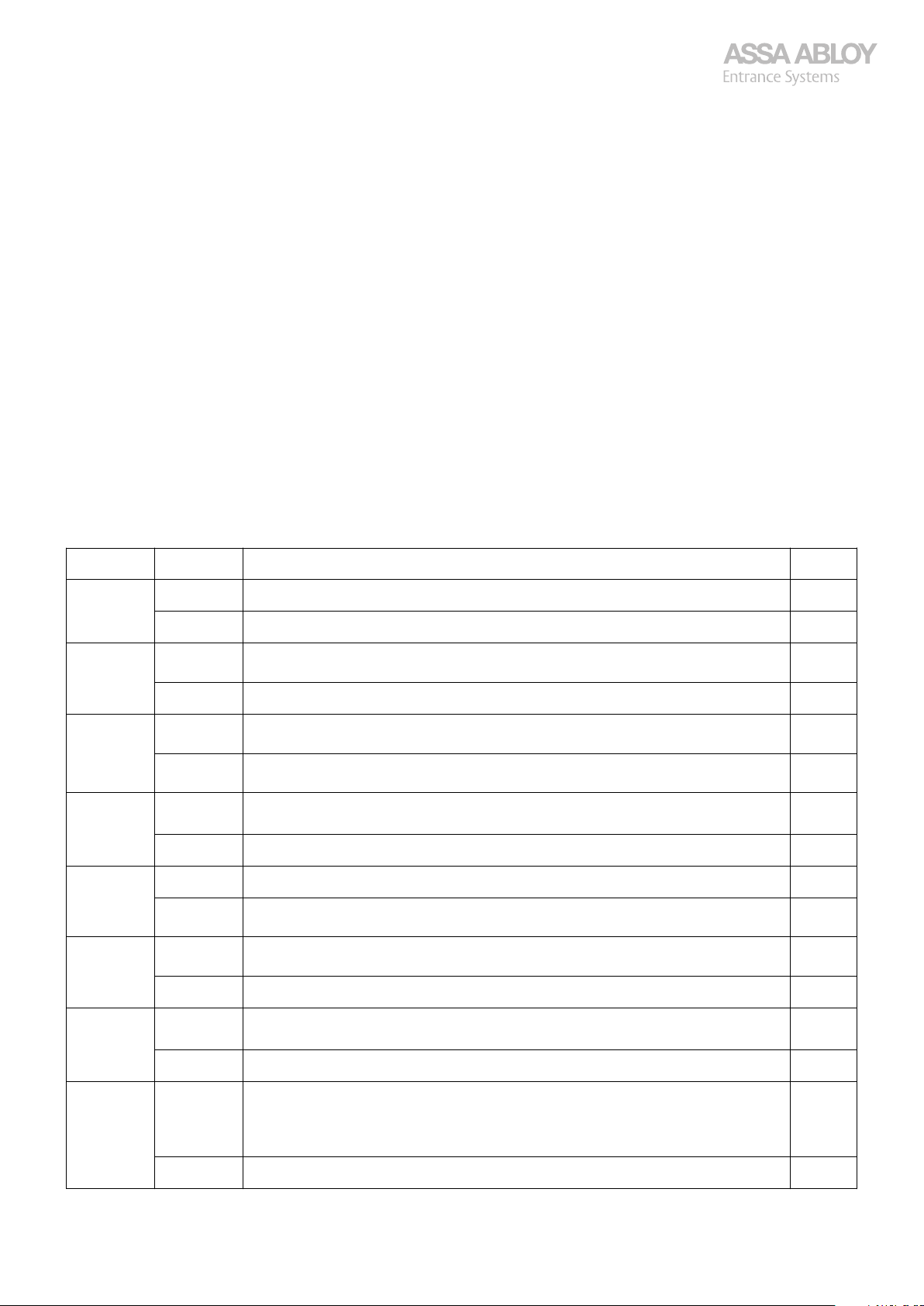
Settings for DIP-switches S1 and S2 and for trim potentiometers T1 and T2.
Switch State Description SW
S1:1 ON Sets the service countdown counter to 50000 cycles All
S1:2 ON Enables that the interlocking relay (X13:7-8-9) indicates all errors except E08, override
S1:3 ON Enables flashing red light (X12:1) between the limit positions.
S1:4 ON Enables red light at fully closed door, both at warning- and traffic lights.
Deactivation of Automatic closing
Press the Up or Down button to operate the door to an intermediate position.
Press and hold the Stop button.
Press and hold the Up and Down buttons for at least 6 seconds
The small dot in the lower right corner of the digital display disappears once the buttons are released again.
DIP-switch-, and trim potentiometers settings
OFF Sets the service countdown counter to default (20000) cycles. All
setting d31.
OFF Interlock relay goes to setting d31. All
Only at warning lights, not at traffic lights.
OFF Enables steady red light (X12:1) between the limit positions.
Only at warning lights, not at traffic lights.
Green light (X12:2) is, if connected, always on at fully open door, no adjustments.
OFF Disables red light at fully closed door, both at warning and traffic lights. All
All
All
All
All
S1:5 ON Enables flashing red light before automatic closing (T2). All
OFF Steady red light before automatic closing (T2).
Only at warning lights, not at traffic lights.
S1:6 ON Disables open outside command at traffic lights for 10 seconds in order to avoid un-
wanted activation from, for instance, outer magnetic loop on the way out.
OFF Enables open outside. All
S1:7 ON Enables direction sensing traffic lights.
Controls opposing traffic by red and green light.
OFF Enables indication; door moves up (X12:3) and door moves down (X12:4). All
S1:8 ON Enables FR-function (French warning Light).
All commands except safety delayed 2.5 seconds while red warning lights are Flashing
(X12:1+J6). At automatic closing T2 replaced by the 2.5 seconds. Red traffic lights illuminates steady during T2.
OFF No delays, T2 sets "pre-flash". All
CDM9 Door Operator 23
All
All
All
All
Page 24
Configuration manual, installation and service
920-950 Docking
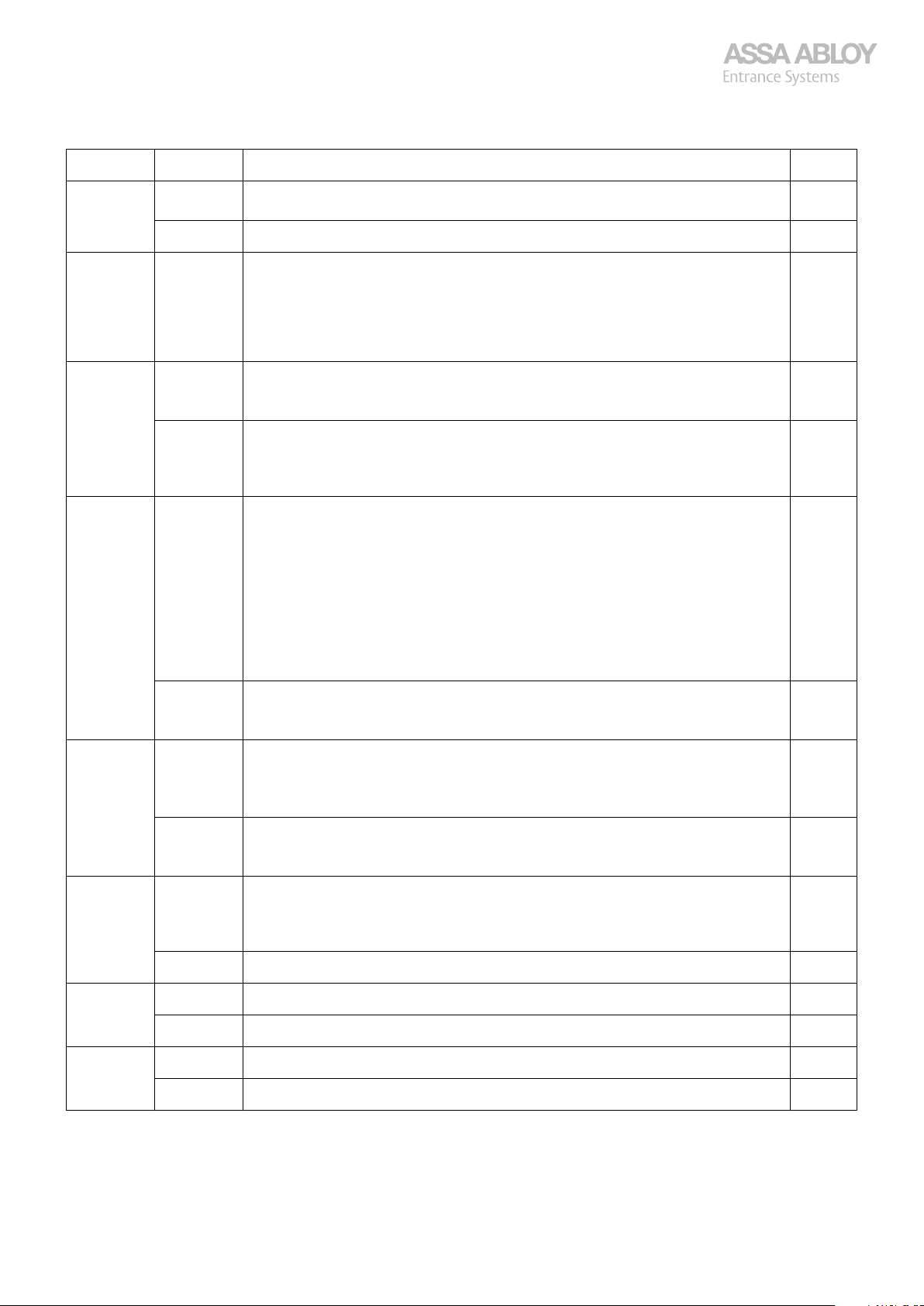
Switch State Description SW
S2:1 ON ON Enables DK-function (Danish safety function). The operator switches permanently
to Hold-to-Run mode if the safety edge activated, until reset at floor.
OFF Normal safety edge function. All
S2:2 (ON) To set reduced opening and fire alarm position, put the door in the required position
and toggle the switch from OFF to ON and back to OFF.
Always make a new door installation before to update door travel length!
Note:
Reduced opening does not work in Hold-to-Run mode -A15. A new installation erases
the position!
S2:3 ON Enables automatic closing only after passing of the safety photocell, T1+T2
Note:
Only if automatic closing active. Can be combined with S2:5 ON
OFF Automatic closing from open position with T1 + T2.
Note:
If automatic closing activated, any open/safety/stop command re-start automatic
closing from T1
S2:4 ON Times for automatic closing after passing photocell.
Automatic closing time T1 doubled if no photocell or/and additional safety are triggered.
Note:
Door closes automatically even if no photocell has been triggered!
Automatic closing time T1 halved if photocell triggered.
Note:
Only if automatic closing active.
Both safety photocell (S2:3 ON) and/or additional safety systems (S2:5 ON) are able
to trigger.
OFF Triggering photocell gives new count from T1.
Note:
Any open/safety/stop command re-start automatic closing from T1.
S2:5 ON Enables Automatic closing only after triggering of the additional safety X8:5-6, T1+T2
Only if automatic closing is activated. Can be combined with S2:3 ON.
Note:
Additional safety works with a normally open contact.
OFF Additional safety, connected to X8:5-6 do not trigger Automatic Closing.
Note:
Any open/safety/stop command re-start automatic closing from T1
S2:6 ON Enables OPEN-command memory to an interlocked door.
Note:
If an interlocked door gets an OPEN-command, the command is stored. When interlocking ends, the door opens from memory.
OFF No OPEN-command memory. All
All
All
All
All
All
All
All
All
All
S2:7 ON Enables 1-900 seconds on T1. All
OFF T1 goes from 1-80 seconds. All
S2:8 ON Enables alternating up-stop-down All
OFF One-button function; up from closed, down from open, reverse from moving down. All
CDM9 Door Operator 24
Page 25
Configuration manual, installation and service
920-950 Docking
3.13
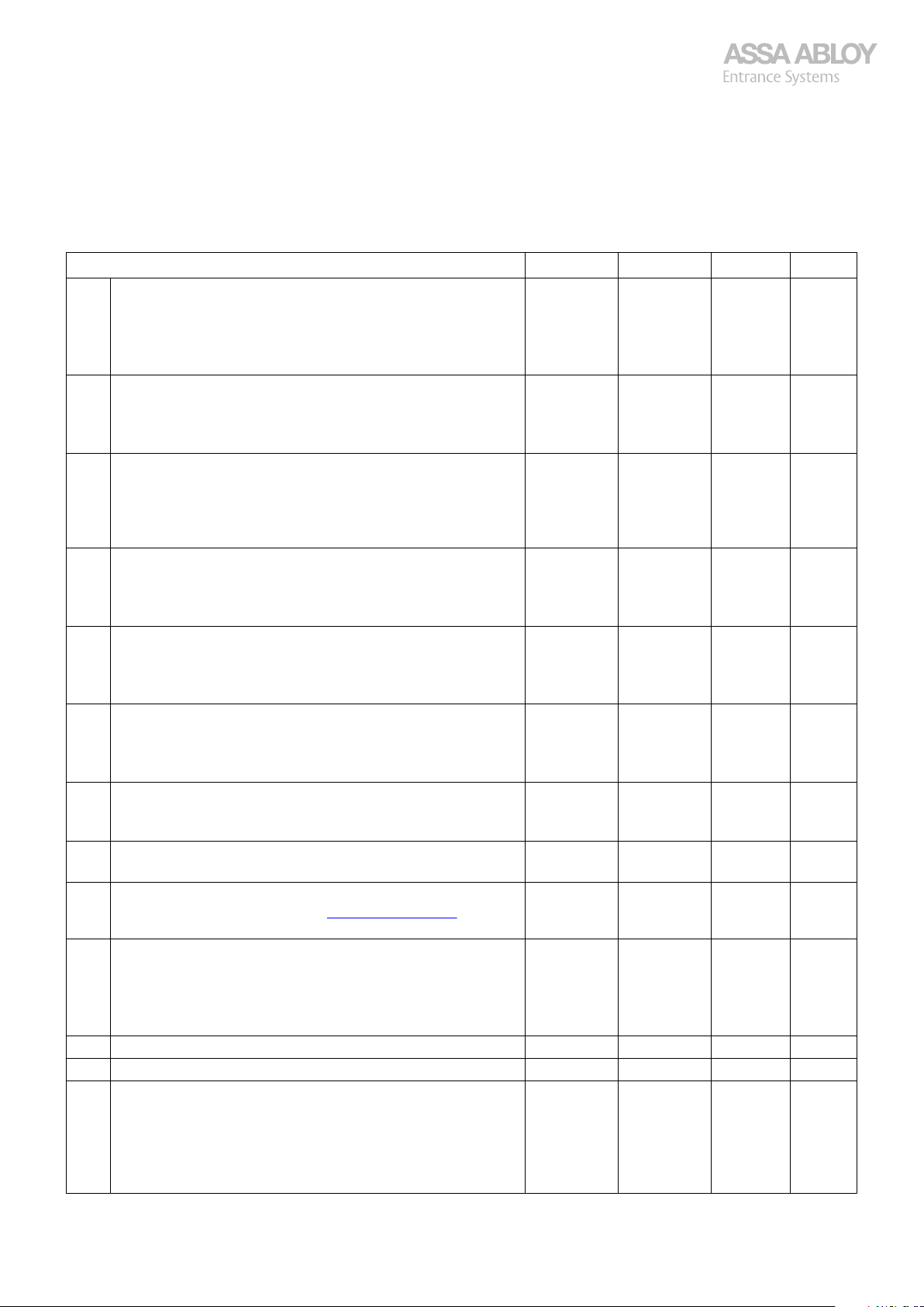
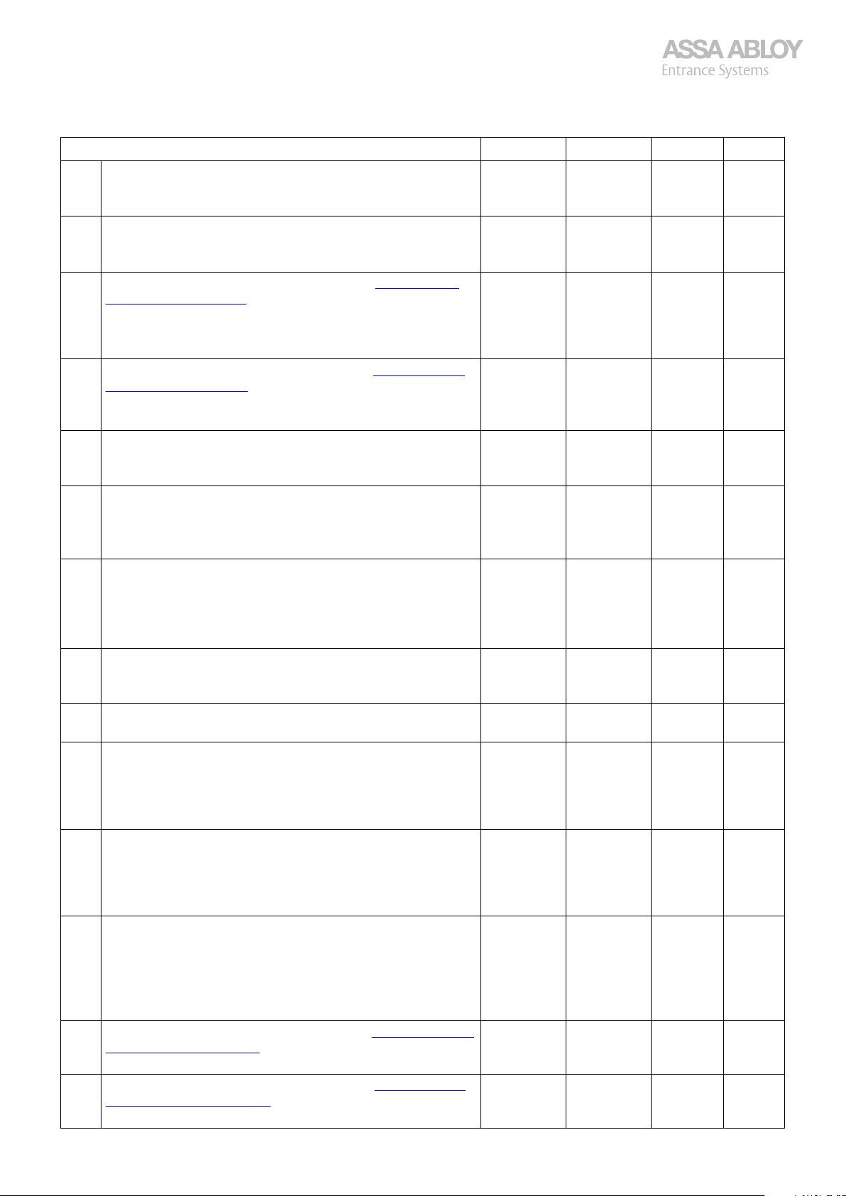
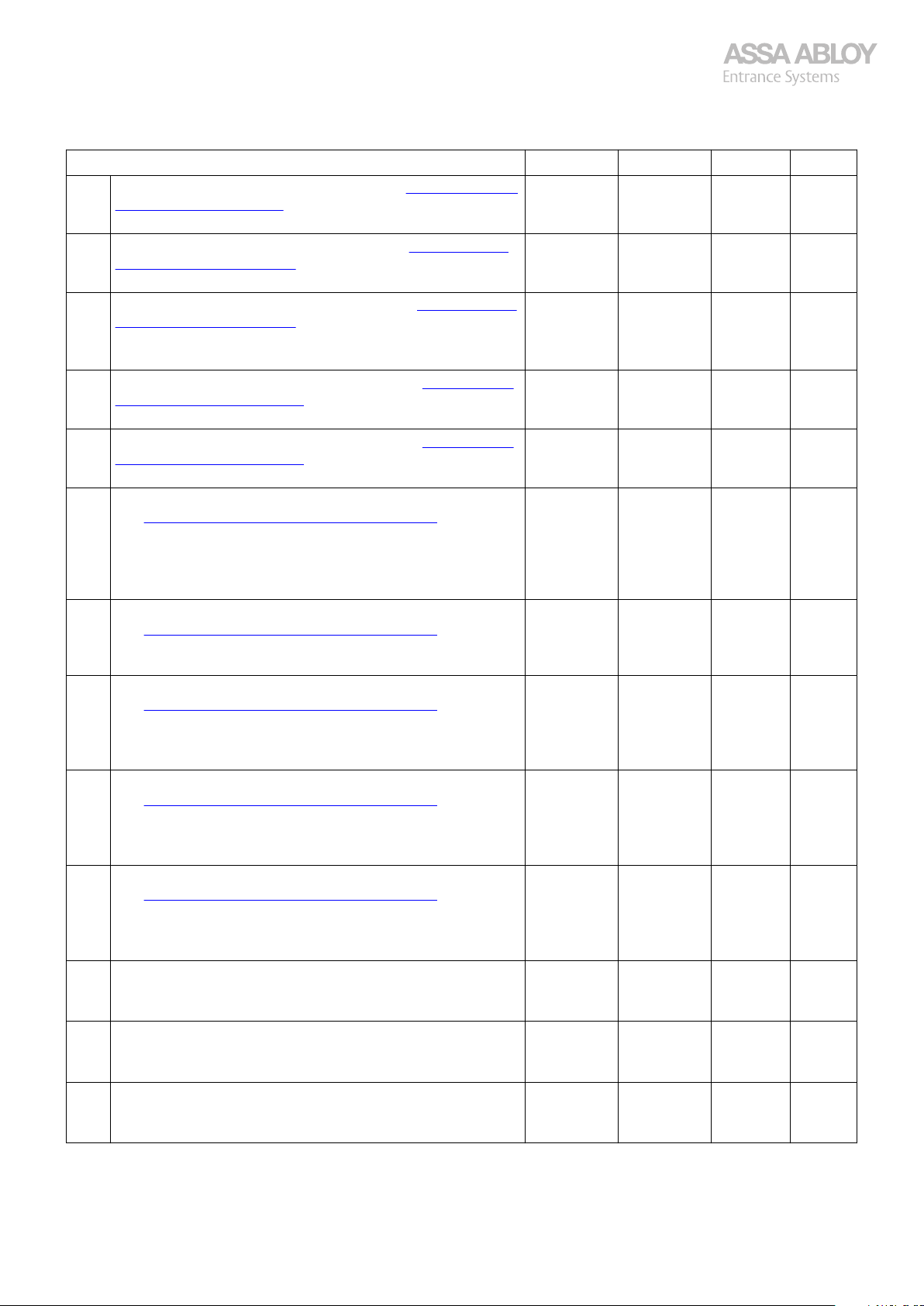
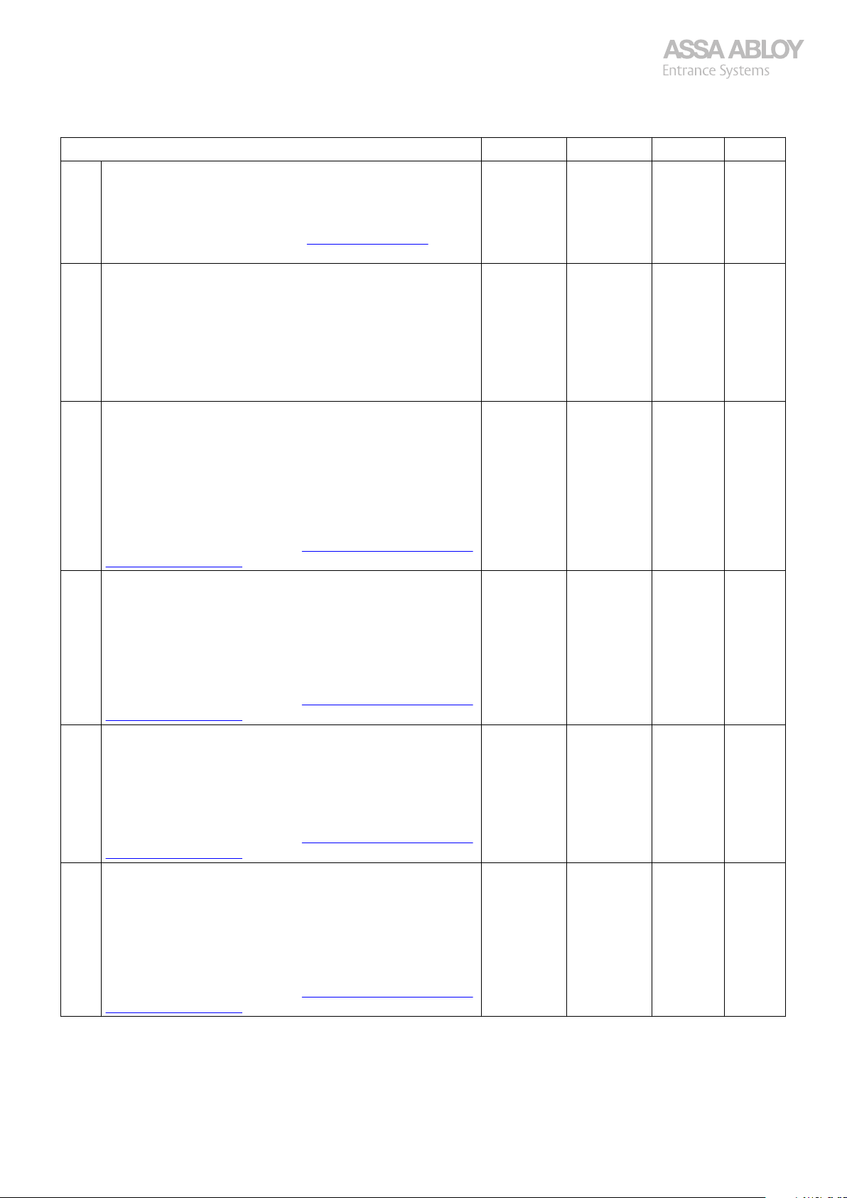
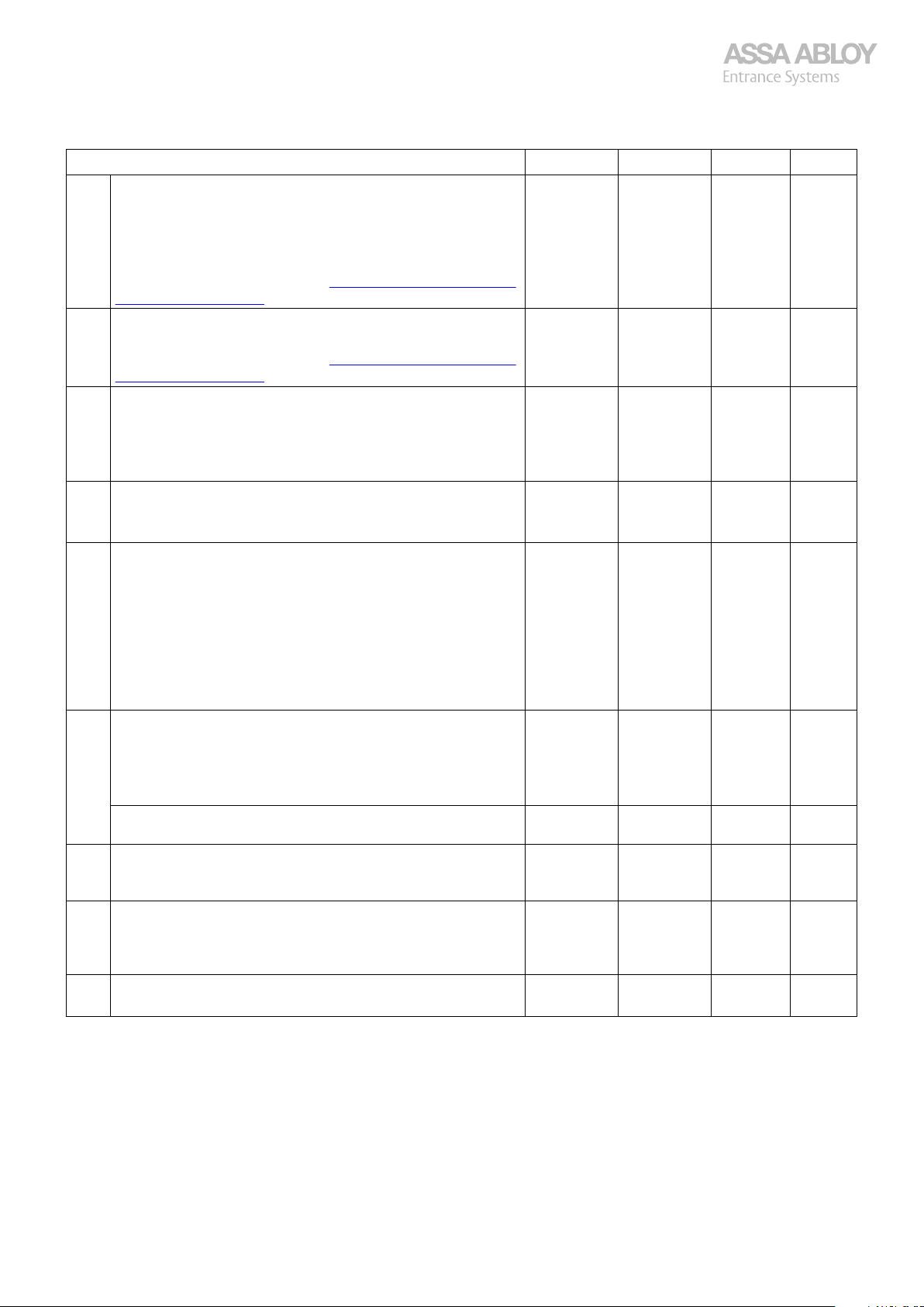
The table below lists the menu choices available for SW1 and SW2, the function of BUTTON 1 and if it is possible to store
values in the internal memory within the menu. The function of BUTTON 1 is different in the different menus.
Not applicable for CDM9 FD.
Functions - DOOR menu Default BUTTON 1 Save SW
d01 Displays time for automatic closing T1 (in seconds).
d02 Displays time for pre-flashing T2, 1 - 32 seconds.
d03 Displays the total number of door cycles (x1000).
d04 Displays and resets the number of door cycles (x1000) since the
d05 Displays the total operating time (in 24 h days).
d06 Displays and resets the operating time (in 24 h days) since the
d07 Sets the limit for the service indicator in number of door cycles
d08 Sets the limit for the service indicator in operating days.
d09 Displays the door error log with the most recent error first, E08 is
d0A Sets automatic exit from service menu after 30 seconds if BUT-
d0b Displays current torque step of CDM9 operator. 9 Refresh No All
d0C Displays the active door errors with highest priority first. - +1 No All
d0d Resets cycles, operating time, and error log
Functions in the Door menu, submenu choice [d]
- - No *A10Set by potentiometer T1 on the C-processor board.
Changes as the corresponding potentiometer turns.
*Alternative method to read the values in the display: switch
SW2 to ON
- - No *A10Set by potentiometer T2 on the C-processor board.
*Alternative method: To read the values in the display: switch
SW2 to ON
- +1 Yes All
If the cycles are ≤100 it is possible to count up the cycle counter
by pushing BUTTON 1.
Displays total operating cycles and is read-only, if no changes are
allowed.
- 0 Yes All
last reset.
Resettable by BUTTON 1.
To reset the counter, ENTER and SAVE the new value as zero (0).
- +1 Yes All
If the operating time is 0 it is possible to increase the operating
time by pushing BUTTON 1, otherwise read-only.
Read-only, if no changes are allowed.
- 0 Yes All
last reset.
Resettable by BUTTON 1.
To reset the counter, ENTER and SAVE the new value as zero (0).
20 +1 Yes All
(x1000).
Service interval disabled when set to 0.
365 +1 Yes All
Service interval disabled when set to 0.
- +1 Yes All
not stored in this log., see section 3.13.2. Error log, d09
on page 30
0 0/1 Yes All
TON 1 or BUTTON 2 has not been pushed.
0 = Automatically exits the menu system after time-out.
1 = Automatically exits the menu system disabled.
Reset to zero (0) after a power break.
0 0/1 Yes A16-
(equivalent to resetting d04, d06, and d09).
0 = No change.
1 = Resets counters and error log. When SAVE is selected, resets
the counters. Always initiated to zero (0) if left and then re-entered.
*C13-
*C13-
C16-
CDM9 Door Operator 25
Page 26
Configuration manual, installation and service
920-950 Docking
Functions - DOOR menu Default BUTTON 1 Save SW
d10 Does not display error E04 when door is installed hold-to-run.
0 = displays E04 when error.
1 = Does not display E04 (still activated but not displayed).
d11 Resets brand unique settings.
0 = Unblocked.
1 = In use for AAES.
d12 Disable OPEN command on the lid, see section 3.13.3. Disable
up command on lid, d12 on page 30.
0 = Normal mode.
1 = System ignores OPEN-commands from the buttons on the
lid.
d13 Overrides the timer for Auto close, see section 3.13.4. Override
timer for Auto close, d13 on page 30.
0 = No override time.
1 - 999 = Timer active and time in seconds.
d14 Single cycle.
0 = Displays single cycles.
1 = Displays thousand cycles.
d15 Selects auto close positions.
0 = Auto close from both reduced opening and fully open.
1 = Auto close only from fully opened position.
2 = Auto close only from reduced opening.
d16 Selects pre-warning lights mode when performing auto close, if
pre-warning lights are active.
0 = Pre-warning from all positions.
1 = Pre-warning only from the fully open position.
2 = Pre-warning only from the reduced open position.
d17 Activates the magnetic lock.
0 = Magnetic lock not active.
1 = Magnetic lock active.
d18 Time before the door starts to move if magnetic lock is active.
Time expressed in tenths of seconds 5-20. (i.e. 5 = 0.5 s).
d19 Auto closes after photocell triggering behavior.
0 = T1 triggers after any interruption time.
1 = Auto close interrupted by the photocell longer than set d20
time initiates an immediate (T2) retry. Shorter Triggering time
gives T1.
d20 Vehicle traffic filter.
Time the photocell needs to be activated to trigger an immediate close command (immediate = time T1 is skipped but T2 remains).
Time expressed in tenths of seconds 5-40 (i.e. 10 = 1 s).
d21 Selects predefined configuration.
0 = Default factory values.
1 = UPS (Uninterrupted Power Supply) configuration, battery
backup system.
2 = Read only. Is automatically set if something in the default set-
tings has been changed.
d22 Selects function for input X08:1-2, see section 3.13.5. Configura-
ble input options, d22-d28 on page 30.
Default = Open door.
d23 Selects function for input X08: 3-4, see section 3.13.5. Configu-
rable input options, d22-d28 on page 30.
Default = One button function.
0 0/1 Yes All
0 0/1 Yes All
0 0/1 Yes All
0 +1 Yes All
1 0/1 Yes C14-
0 +1 Yes C15-
0 +1 Yes C15-
0 0/1 Yes C15-
5 +1 Yes C15-
0 0/1 Yes C18-
10 +1 Yes C15-
0 +1 Yes C15-
1 +1 Yes C15-
2 +1 Yes C15-
CDM9 Door Operator 26
Page 27
Configuration manual, installation and service
920-950 Docking
Functions - DOOR menu Default BUTTON 1 Save SW
d24 Selects function for input X08:5-6, see section 3.13.5. Configura-
ble input options, d22-d28 on page 30.
Default = Extra safety.
d25 Selects function for input X08: 7-8, see section 3.13.5. Configu-
rable input options, d22-d28 on page 30.
Default = Interlock.
d26 Selects function for input X08: 9-10, see section 3.13.5. Configu-
rable input options, d22-d28 on page 30.
Default = Open inside.
UPS config = Fire alarm.
d27 Selects function for input X08:11-12, see section 3.13.5. Config-
urable input options, d22-d28 on page 30.
Default = Open outside.
d28 Selects function for input X08:13-14, see section 3.13.5. Config-
urable input options, d22-d28 on page 30.
Default = Open to reduced opening.
d29 Selects function for output X13:1-2-3, D-kit mandatory, see sec-
tion 3.13.6. Configurable output options, d29 – d33
on page 31.
Factory default = Opened limit switch.
UPS config = Fire alarms accepted, i.e. the door can respond to a
fire alarm.
d30 Selects function for output X13: 4-5-6, D-kit mandatory, see sec-
tion 3.13.6. Configurable output options, d29 – d33
on page 31.
Factory default = Closed limit switch.
d31 Selects function for output X13:7-8-9, D-kit mandatory, see sec-
tion 3.13.6. Configurable output options, d29 – d33
on page 31.
Factory default = Interlock (if dip switch S1:2 is OFF).
UPS config = Photocell active, i.e. blocked.
d32 Selects function for output J6 (24-30 VDC, max 12mA), see sec-
tion 3.13.6. Configurable output options, d29 – d33
on page 31.
Factory default = French warning lights.
UPS config = Magnetic lock.
d33 Selects function for output J7 (24-30 VDC, max 12mA), see sec-
tion 3.13.6. Configurable output options, d29 – d33
on page 31.
Factory default = Light curtain test function.
UPS config = Door moving.
d34 Configures output J6 as normally closed or normally open.
0 = Normally open.
1 = Normally closed.
d35 Configures output J7 as normally closed or normally open.
0 = Normally open.
1 = Normally closed.
d36 Displays full SW version number.
Display scrolls sideways to show version:
A xx-xx-xx, variant: Std, 2H, HD, FD or S, B xx-xx, C xx-xx-xx.
3 +1 Yes C15-
4 +1 Yes C15-
5 +1 Yes C15-
6 +1 Yes C15-
7 +1 Yes C15-
1 +1 Yes C15-
2 +1 Yes C15-
3 +1 Yes C15-
4 +1 Yes C15-
0 +1 Yes C15-
0 0/1 Yes C15-
0 0/1 Yes C15-
- Refresh Yes C15-
CDM9 Door Operator 27
Page 28
Configuration manual, installation and service
920-950 Docking
Functions - DOOR menu Default BUTTON 1 Save SW
d37 Governs whether toggling switch S2:2 defines the reduced open
position or the fire alarm position. Selection reverts to default
when the power is position turned off.
0 = Reduced open position.
1 = Fire alarm position, see section
on page 29.
d38 Top adjustment, in % of default distance to the top. Range 0-300
0 = Top position is with buffers compressed as far as possible.
300 = The door stops at a top position of 3* the default distance,
enabling long buffers to be compressed in a suitable way. To
avoid a door jumping against the buffers, decrease the distance
in order to compress the buffers more.
Not applicable for CDM9 FD.
For more information.
d39 Slow speed area at top adjustment, in % of default area.
Works both downwards and upwards.Add that the a change will
also increase the crawl speed area, d40 change might be needed
as well.
Range 0-300 (Std, 2H and HD default: 100. S default: 120. VL default: 50). 0 = Remove slow speed area at top.
300 = Slow speed area is 3* the default area.
Not applicable for CDM9 FD.
For more information, see section
up and down, d38 - d44 on page 32.
d40 Crawl speed area inside slow speed area (set in d39) at top ad-
justment, in % of default area.
Only working downwards.
Range 0-100.
0 = No crawl speed area.
100 = Crawl speed area is the same as slow speed area.
Not applicable for CDM9 FD.
For more information, see section
up and down, d38 - d44 on page 32.
d41 Slow speed area at floor adjustment, in % of default area.
Only working downwards.
Range 0-300
0 = Remove slow speed area at floor.
300 = Slow speed area is 3* the default area.
Not applicable for CDM9 FD.
For more information, see section
up and down, d38 - d44 on page 32.
d42 MENU NOT ACTIVE.
Crawl speed area inside slow speed area (which is set in d41) a at
floor adjustment, in % of default area.
Range 0-100
0 = No crawl speed area.
100 = Crawl speed area is the same as slow speed area.
Not applicable for CDM9 FD.
For more information, see section
up and down, d38 - d44 on page 32.
3.13.1. Fire alarm, FIA
3.13.7. Speed area options for
3.13.7. Speed area options for
3.13.7. Speed area options for
3.13.7. Speed area options for
0 0/1 Yes C15-
100 +10 Yes A15-
Std, 2H, HD
100
S 120
VL 50
Std, 2H, HD
0
S 20
VL 0
50 +10 Yes A17-
0 +10 Yes A17-
+10 Yes A15-
+10 Yes A17-
C15-
C16-
C16-
C16-
C16-
CDM9 Door Operator 28
Page 29
Configuration manual, installation and service
920-950 Docking
Functions - DOOR menu Default BUTTON 1 Save SW
d43 Crawl speed, the slowest possible speed the motor can run, in %
of default crawl speed.
Range 100-200.
100 = Slowest possible speed.
Not applicable for CDM9 FD.
For more information, see section
up and down, d38 - d44 on page 32.
d44 Speed of door, in % of default speed. Range 30-100.
100 = Normal speed.
For more information, see section 3.13.7. Speed area options for
up and down, d38 - d44 on page 32.
d45 Locks the door settings d38-d44, d47 and d48 from being set to
default during reset by menu d21 and installation, also lock the
2H full speed light curtain setting.
0 = Unlocked.
1 = Locked
d46 Service indicator light.
0: Steady light
1: Flashing light
d47 50 mm above floor position adjustment.
Adjusts the position of door where safety edge is disabled, to
avoid reversing when reaching the floor.
Door moves to default position, secures that it is 50 mm above
floor or uses menu to adjust until it is in position. After SAVE, the
door moves to new position.
Range: 30-80.
Improves the function when the door is trying to open when
locked (Lock Bolt) and close again.
d48 Clutch release distance, in % of maximum distance that the door
reverses after reaching fully closed position. Releases the clutch
and removes the mechanical tension in the gearbox to limit the
force needed to disengage the door.
Range 0-100.
For CDM9 FD. 5 +5 Yes A20-
d49 Timer for how a long the additional photocell needs to be activa-
ted in order to be a trigger for automatic closing. 1 = 0,1 s, max
time 10 s.
d50 Timer for Configurable output SIB function, door movement de-
layed from closed position and the Configurable output is active
as soon as the open command is given. 0 is off, range 0-30 s.
Countdown in the display.
d51 Remote setting (IoT) of auto close timers T1 and T2, the T1 and
T2 potentiometers are bypassed.
3.13.7. Speed area options for
100 +10 Yes A17-
100 +10 Yes A17-
0 0/1 Yes A17-
0 0/1 Yes C16-
50 +5 Yes A17-
45
(SW-A20)
35
(SW A21-)
0 +1 Yes A17-
0 +1 Yes A17-
0 0/1 Yes A17-
+5 Yes A20-
C16-
C16-
C16-
C16-
C18-
C18-
C20-
C20-
C20-
3.13.1
By setting d37 to 1 the S2:2 switch can used to set a required Fire alarm position.
Run the door to the requested position and set it by switching S2:2 ON-OFF for a few seconds.
·
Set one of the configurable input options, either 8 (NO-contact) or 11 (NC-contact), for the fire alarm function. With this
·
configurable input, the door will go to the set position, up or down and will remain locked in this position as long as the
configurable inputs is active.
As soon as the configurable input is active, the letters FIA are displayed. FIA stays on the display until the configurable input is
not active and the door is closed. The door must be closed once after a Fire alarm to make sure the safety edge is checked.
When the safety edge is checked, FIA will be cleared from the display.
CDM9 Door Operator 29
Fire alarm, FIA
Page 30
Configuration manual, installation and service
920-950 Docking
If the power of the door is set OFF-ON, the door will automatically reset to fully open position and go to the fire alarm position
again. If a Fire alarm is on when the power is turned ON the door resets fully to open position and goes to fire position. Since
the door may move down automatically (depends on the door position required) an additional safety photocell might be
mandatory. Stop and safety functions are working during Fire alarm.
If a safety or up command is given during fire alarm, the door will reverse. When the safety command is not active anymore,
the door will try to go to the fire alarm position again. With PNE it will stop in open position after five failed attempts in a row,
one need then to give a down command to re-start it, with Light Curtain and PHC it will keep trying. If a stop has been
activated, the door will try to go to the fire again position again 10 s after the stop is no longer activated.
In combination with a D-kit and the configurable output functions 5 (the control unit is ready to receive a Fire alarm
command, no errors etc. are active) and 9 (the door has reached the required Fire alarm position) one can further optimize
this function for the end user.
3.13.2
Displays the error log, and contains important information about errors that recently appeared. Errors are displayed in order of
priority, with most recent error first. When the error log has come to the end (maximum 15 errors), "END" is displayed. Push
BUTTON 1 to step back in time in the error log.
For easier contact with the help desk regarding operator and/or software, write down the information from the error log while
troubleshooting.
Error log, d09
Erase error log
1.
Use BUTTON 1 to step to menu d09.
2.
Enter with BUTTON 2. SAVE displays the message "End".
The error log is erased.
3.13.3
D12 blocks the OPEN buttons on the lid.
Value one (1) for d12; the system ignores the OPEN/REDUCED-OPEN buttons on the lid, X2 and X7:1.
·
Value zero (0) for d12; the system responds to the OPEN button and the REDUCED-OPEN button on the lid.
·
The OPEN door inputs on X8 works regardless of menu d12 setting.
·
3.13.4
A timer that overrides any prerequisite auto close requirements can be activated. If the value for menu d13 is a non-zero value,
the system uses this value as seconds for a timer that overrides any prerequisite for auto close requirements such as S2:3
(automatic closing after passing of the photocell) and S2:5 (automatic closing after additional safety). The door closes
regardless of a photocell exists, if it has not been triggered, or if the extra safety has not been triggered. It is not possible to
supersede an active OPEN-command.
Disable up command on lid, d12
Override timer for Auto close, d13
Auto close must be active.
The time can be set between 1 and 999 s, if it is set to zero (0) the timer will be inactive and not override the prerequisite auto
close requirements.
3.13.5
It is possible to configure the different inputs to other functions using the SERVICE TOOL, e.g. using the SERVICE TOOL to set
menu d22 to option 3 causes the X08:1-2 input to function as extra safety.
Only one input can configured for each function, if menu d22, e.g. is set to 3, no other menu can have this option.
An input is deactivated if zero (0) is chosen, useful during trouble shooting. A door re-installation does not change
configuration of inputs.
Setting Description SW
0 No function C151 Open door C152 One button function C153 Extra safety C154 Interlock C15-
CDM9 Door Operator 30
Configurable input options, d22-d28
Page 31
Configuration manual, installation and service
920-950 Docking
Setting Description SW
5 Open inside C156 Open outside C157 Reduced opening.
Input active when door reaches reduced position gives stop, further opening disabled with input
high.
8 Fire Alarm, normally open (NO) C159 Auto close activation, this setting/input has highest priority C1610 Reduced opening with pulse function.
Input gives open command and door stop at reduced position.
Open command gives fully open door.
11 Fire alarm, normally closed (NC) C18-
C15-
C16-
3.13.6
Only one output can be configured for each function, if menu d29 is e.g. set to 3, no other menu can have this option.
An input/output is deactivated if zero (0) is chosen, useful during trouble shooting. A door re-installation does not change
configuration of outputs.
Setting Description SW
0 No function (light curtain test function for output J7 with menu d33) C151 Open limit switch C152 Close limit switch C153 Interlocking C154 French warning Light C155 Fire alarm accepted, door is allowed to move to fire alarm position. No error etc. C156 Additional photocell, X03:1-2, blocked C157 Magnetic lock. Output on when the door is moving. C158 Door moving C159 Fire alarm acknowledge,; door has completed its fire alarm movement C1510 Service required same as the SERVICE INDICATOR, but not flashing. C1811 SIB function, see also d50 C20-
Configurable output options, d29 – d33
CDM9 Door Operator 31
Page 32
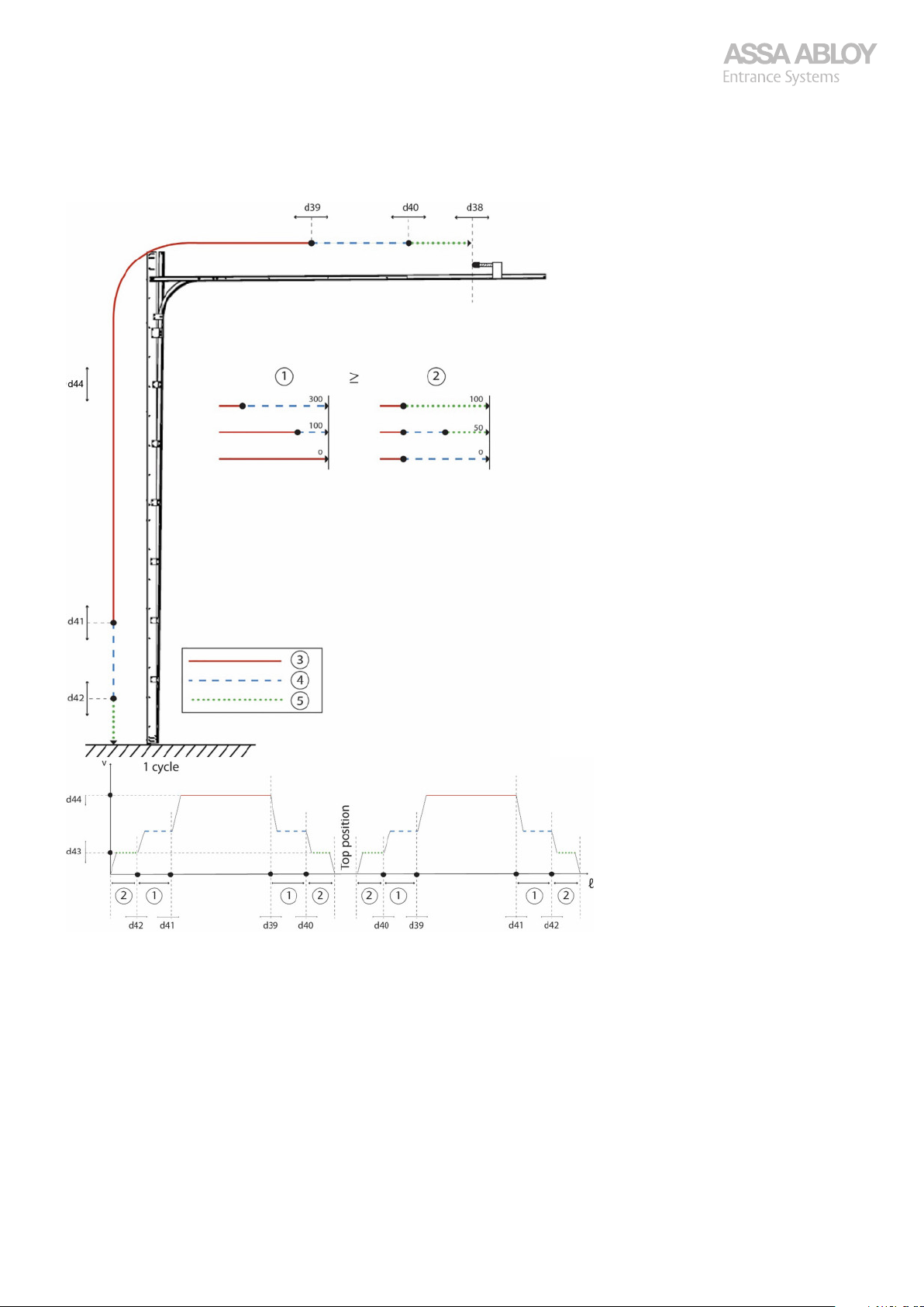
Configuration manual, installation and service
920-950 Docking
3.13.7
It is recommended to lock the values in menu d45.
Speed area options for up and down, d38 - d44
1.
Slow speed area
2.
Crawl speed area, CDM9S
3.
Normal speed
4.
Slow speed
5.
Crawl speed, CDM9S
CDM9 Door Operator 32
Page 33
Configuration manual, installation and service
920-950 Docking
3.14
3.14.1
Check that the voltage and frequency is within specified limits, if possible, also during operation:
·
·
If the operator does not start, check that the operator has not been disengaged. Try to reset the control unit, by switching off
the main power supply and switch it on again after 5 seconds. If the problem persists troubleshoot the door.
3.14.2
The operator does not start.
Cause Solution
Operator disengaged Engage operator once again.
If the problem persists, test to operate the door until fault symptoms are identified, see section 3.15. Troubleshooting steps
on page 37.
3.14.3
Electrical troubleshooting
Operator faults
Danger!
Electrocution may lead to death. Fatal electric shock when touching live parts. Always disconnect all possible voltage sources before any work on electrical parts. Make sure that re-connection is not possible by locking them.
230 VAC ± 10%.
50 or 60 Hz ± 2 Hz
Disengagement
·
Safety edge
Faults in the safety edge when the door is closing. The door stops quickly and reverses to fully open position.
For opening and hold-to-run for closing, there is an indication of faults in the safety edge.
Cause Solution
Faults, or indication faults, in the safety edge. Automatic reset of the safety edge if it is operational and gets a signal at
the floor (< 50 mm from the floor) during hold-to-run operation down.
A pulse of at least 150 ms is required for the pneumatic safety edge, see
section 3.15.4. Hold-to-run, down on page 39.
If the problem persists, test to operate the door until fault symptoms are identified, see section 3.15. Troubleshooting steps
on page 37.
3.14.4
Incorrect balancing and/or the door getting stuck.
Cause Solution
No acknowledgment impulse obtained for
opening/hold-to-run when closing the door.
The door is located less than 50 mm from the
floor and the safety edge has received no acknowledgment pulse.
The torque guard has been activated. The impulses for opening/hold-to-run for closing are obtained. Check
Balancing
Check the balancing and the mechanical resistance and adjust if nec-
·
essary.
Check the balancing and the mechanical resistance and adjust if nec-
·
essary.
Disengage and put the door into an intermediate position.
·
Engage the operator and check that engagement has taken effect (by
·
pulling the door up and down), see section 3.15.2. Door does not
open on page 37.
·
the balancing and the mechanical resistance and adjust if necessary.
If the problem persists, test to operate the door until fault symptoms are identified, see section 3.15. Troubleshooting steps
on page 37.
3.14.5
Faults occurring on the torque guard, the encoder or in the A-processor board memory.
CDM9 Door Operator 33
Internal electrical fault
Page 34
Configuration manual, installation and service
920-950 Docking
Cause Solution
The operator is put into hold-to-run operation
for both opening and closing.
If the problem persists, test to operate the door until fault symptoms are identified, see section 3.15. Troubleshooting steps
on page 37.
Check the torque guard, the encoder, or in the A-processor board
·
memory.
3.14.6
The operator moves in the wrong direction, the door stops against the floor and is inoperable.
Cause Solution
Inoperable door, due to operator moving in the
wrong direction.
If the problem persists, test to operate the door until fault symptoms are identified, see section 3.15. Troubleshooting steps
on page 37.
3.14.7
The torque guard reverses the door on the way down or stops on the way up.
Cause Solution
The door is not properly balanced. Check the torque guard, the encoder, or in the A-processor board
Exceeded torque limit.
Error code E15 from SW A17- displayed on the
way up.
If the problem persists, test to operate the door until fault symptoms are identified, see section 3.15. Troubleshooting steps
on page 37.
3.14.8
Operator moves in wrong direction
Redo the door installation, see section 3.7. CDM9 Installation
·
on page 15.
Torque guard
·
memory.
Perform a troubleshooting of a reversing or stopping door, see section
·
3.15.5. Door reverses or stops without obvious obstacle on page 39.
Photocell
The door can not be closed, the door stops gently and then reverses to fully open position.
Cause Solution
Fault indicated on the safety photocells. Troubleshoot a door that gently reverses or refuses to close, see sec-
If the problem persists, test to operate the door until fault symptoms are identified, see section 3.15. Troubleshooting steps
on page 37.
3.14.9
Faults in the safety edge.
Cause Solution
Door disengaged The safety edge supervision can be reset automatically if it is opera-
If the problem persists, test to operate the door until fault symptoms are identified, see section 3.15. Troubleshooting steps
on page 37.
3.14.10
The two LEDs, D8 and D9, on the Connector board, indicates the stop circuit, if both are lit the stop circuit is ok. For doors with
magnetic pass door switch, only D9 will be lit.
Door position reset
Stop circuit
·
tion 3.15.7. Gentle reverse or Refuse to close on page 40.
·
tional and gets a signal at the floor (< 50 mm from the floor) during
hold-to-run operation down. A pulse of at least 150 ms is required for
the pneumatic safety edge. If the issue persists, do a troubleshooting
of a door that does not close, see section 3.15.3. Door does not close
on page 38.
CDM9 Door Operator 34
Page 35
Configuration manual, installation and service
920-950 Docking
Cause Solution
Stop circuit not ok. Check the two LEDs D8 and D9, on the Connector board. Are both lit
If the problem persists, test to operate the door until fault symptoms are identified, see section 3.15. Troubleshooting steps
on page 37.
·
the stop circuit is ok. If the door has a magnetic pass door switch, only
the LED D9 will be lit. Perform a troubleshooting of a door that does
not open, see section 3.15.2. Door does not open on page 37.
3.14.11
Cause Solution
E22 displayed before the first installation.
A spare part A-processor board (of versions prior to -A17) always displays E22 before first installation.
If the problem persists, test to operate the door until fault symptoms are identified, see section 3.15. Troubleshooting steps
on page 37.
3.14.12
For CDM9S only.
As of software A20 and B3.01 the CDM9 can be downgraded to a PNE-safety edge.
Cause Solution
Customer can not accept temporary interruptions of the light curtain caused by snow, rain,
or similar.
3.14.13
If the acknowledgment from the installation tool is to short or fail, the installation will not be able to complete. One indication
is that the door does not reverse after a short run in the last step instead it will run all the way down and reverse against the
tool. If the fuses blow all the time during installation (or after some use of the door), it is probably caused by a flash over in the
electrical motor. This is presuming that the mains power is installed in the right way.
The door MUST activate the top beam of the light curtain, the starting beam first and then the other in sequence, 1-2-3 and so
on. Otherwise the grid will be activated and/or the installation will fail.
E22
Do the door installation, see section 3.7. CDM9 Installation
·
on page 15 or check the error indication, see section 3.16. Indication
of errors (E) on page 46.
Light curtain activated by snow, rain, or similar (CDM9S only)
Re-build to a PNE-safety edge and do a new basic installation. The sys-
·
tem detects the function automatically. The door closes in normal
CDM9 speed, but opens with CDM9S speed.
Problems during installation and operation
3.14.13.1
Cause Solution
It is only possible to operate the door in holdto-run up and the door locks out in fully open
position.
The door does not slow down or stop. The encoder is damaged but still counts pulses (but it misses some),
The display shows E23 or E24.The encoder is
damaged or broken.
3.14.13.2
The installation will not be completed if the acknowledgment from the installation tool is too short or fails.
Cause Solution
The door does not reverse after a short run in
the last step instead it runs all the way down
and reverse against the tool.
CDM9 Door Operator 35
Encoder
Installation tool
The encoder is broken, see section 3.15.16. Door stops to operate
·
on page 44.
·
the door loses its position, see section 3.15.16. Door stops to operate
on page 44.
Perform the troubleshooting of a door that stops to operate, see sec-
·
tion 3.15.16. Door stops to operate on page 44.
Check/ replace installation tool.
·
Page 36
Configuration manual, installation and service
920-950 Docking
3.14.13.3
Cause Solution
A flash-over in the electrical motor causes the
fuses to blow during installation.
3.14.13.4
If there is a short circuit or if the values are outside the recommended values, replace the mechanical unit. Replacing the
boards will not help.
Resistance between cables in room temperature:
Variant Resistance (Ω)
CDM9 STD, FD and 2H 18-19
CDM9 HD 12-13
CDM9 S 9-11
3.14.14
Main power supply
Install the main power supply in the right way, see section 3.7. CDM9
·
Installation on page 15.
Check the motor, see section 3.14.13.4. Motor condition
·
on page 36.
Motor condition
Danger!
Electrocution may lead to death. Fatal electric shock when touching live parts. Always disconnect all possible voltage sources before any work on electrical parts. Make sure that re-connection is not possible by locking them.
Additional equipment faults
3.14.14.1
D1 Interlocking and red light. Including warning lights
D2 Interlocking and magnetic loop
D3 (D7) Interlocking
D4 Interlocking, magnetic loop, and red light including warning lights
D5 Interlocking and traffic lights
D6 Interlocking, magnetic loop, and traffic lights
3.14.14.2
Warning light red, see section 3.15.10. Warning / traffic lights on page 41.
·
Relay kit, see section 3.15.11. Relays on D-Board on page 42.
·
Interlocking, see section 3.15.12. Interlocking relay on page 43.
·
24 VAC for external consumer, see section 3.15.13. Power on X14 on page 43.
·
3.14.14.3
Magnetic loop amplifier connections, see section 3.15.13. Power on X14 on page 43.
·
Relay kit, see section 3.15.11. Relays on D-Board on page 42.
·
Interlocking, see section 3.15.12. Interlocking relay on page 43.
·
24 VAC for external consumer, see section 3.15.13. Power on X14 on page 43.
·
3.14.14.4
Relay kit, see section 3.15.11. Relays on D-Board on page 42.
·
Interlocking, see section 3.15.12. Interlocking relay on page 43.
·
24 VAC for external consumer, see section 3.15.13. Power on X14 on page 43.
·
Additional kits overview
No function on D1, Interlocking and red light (including warning lights)
No function on D2, Interlocking and magnetic loop
No function on D3 and D7, Interlocking
3.14.14.5
Magnetic loop amplifier connections, see section 3.15.13. Power on X14 on page 43.
·
Warning light red, see section 3.15.10. Warning / traffic lights on page 41.
·
24 VAC for external consumer, see section 3.15.13. Power on X14 on page 43.
·
CDM9 Door Operator 36
No function on D4, Interlocking, magnetic loop, and red light including warning lights
Page 37
Configuration manual, installation and service
920-950 Docking
Relay kit, see section 3.15.11. Relays on D-Board on page 42.
·
Interlocking, see section 3.15.12. Interlocking relay on page 43.
·
3.14.14.6
Traffic lights, see section 3.15.10. Warning / traffic lights on page 41.
·
Relay kit, see section 3.15.11. Relays on D-Board on page 42.
·
Interlocking, see section 3.15.12. Interlocking relay on page 43.
·
24 VAC for external consumer, see section 3.15.13. Power on X14 on page 43.
·
3.14.14.7
Magnetic loop amplifier connections, see section
·
Traffic lights, see section 3.15.10. Warning / traffic lights on page 41.
·
Relay kit, see section 3.15.11. Relays on D-Board on page 42.
·
Interlocking, see section 3.15.12. Interlocking relay on page 43.
·
24 VAC for external consumer, see section 3.15.13. Power on X14 on page 43.
·
3.15
3.15.1
Door does not reverse on the floor during installation.
Cause Solution
Torque too low. Adjust torque.
Photocell in rail installation activated. Reinstall without photocell in rail activated.
Bad signal from the PNE safety edge, a lot of
very short signals instead of one signal, at least
150 ms. Does not always show on D4-D5.
The cables from the electric motor to the power PCB are switched, wrong order.
No function on D5, Interlocking and traffic lights
No function on D6, Interlocking, magnetic loop, and traffic lights
3.15.13. Power on X14 on page 43.
Troubleshooting steps
Follow each step in the table. If the problem on the row is not applicable, continue with the next row. The
whole table must be checked from top to bottom.
Start over from the top of the trouble shooting if something has been replaced.
Door does not reverse during installation
·
·
Make sure the photocells are activated before the door reaches the
·
floor, see section 3.7. CDM9 Installation on page 15.
Check and adjust the bottom sealing, the PNE safety edge, and the
·
hose.
Install the door without PNE safety edge in order to isolate the prob-
·
lem, see section 3.7. CDM9 Installation on page 15.
Replace the broken parts of the PNE safety edge.
·
Make sure the cables are correctly connected. See color markings on
·
the PWR-board.
Replace the A-processor board.
·
Operate the door for a while and check all functions.
For information on error codes for the door, see section 3.16. Indication of errors (E) on page 46.
3.15.2
The door does not start when the OPEN button is activated.
Cause Solution
Open button does not work. Check setting of d12. Disable the OPEN button in the lid, should be set
X4 and X5 are not correctly connected. Open the lid of the control box and check that the contacts X4 and X5
CDM9 Door Operator 37
Door does not open
·
to 0 to have the OPEN button enabled.
·
for the lid are connected correctly
Check that the contact block with jumpers is mounted on X2 and X3.
·
Check in the normal mode (not the installation mode) that there is no
·
24 VAC between X1:7 and X1:1 or X1:3, when neither the OPEN nor
CLOSE button has been activated.
If 24 VAC is present, check if one of the buttons is stuck.
Page 38
Configuration manual, installation and service
920-950 Docking
Cause Solution
No 24 VAC between X1:6 and X1:7. Check the supply current to the CEE outlet of the mechanical unit—
No 24 VAC between X1:7 and X7:2. Replace the connector board.
No 24 VAC between X1:7 and X7:3. Check the external STOP button.
No 24 VAC between X1:7 and X1:2. Check the STOP button in the lid, the contact X4, and contact block X2
No 24 VAC between X1:7 and X7:5. Replace the connector board.
No 24 VAC between X1:7 and X1:5. Check contact X3 and the jumper mounted between1-2, possibly re-
The OPEN button in the lid is activated, but no
24 VAC between X1:7 and X1:1.
The OPEN button in the lid is activated, but no
24 VAC between X1:7 and X5:2.
Redo the door installation, see section 3.7. CDM9 Installation on page 15.
The door cannot be operated upward using the
OPEN or CLOSE button.
Complete the installation, see section 3.7. CDM9 Installation on page 15. In case of errors, perform an electrical troubleshooting, see section 3.14. Electrical troubleshooting on page 33.
Door is not working OK. Check for fault symptoms in other section in this troubleshooting
·
230 VAC.
Check the mains fuse for the output.
·
Check the mains and control cables.
·
Check if automatic fuse for 24 VAC is triggered.
·
Check for short circuit on the 24 VAC.
·
Replace mains and control cables.
·
Replace the power board and the A-processor board.
·
Redo the door installation, see section 3.7. CDM9 Installation
·
on page 15.
·
·
·
with jumper mounted between pins3-4.
Replace the connector board.
·
·
·
place connector board in the control box.
Check the voltage, 24 VAC between X1:7 and X5:1.
·
Replace the connector board.
·
Check the voltage.
·
Replace the keypad on the lid.
·
Replace the connector board.
·
Check that the door is not disengaged.
·
Check / replace the control cable.
·
Replace the power board and the A-processor board.
·
Redo the door installation, see section 3.7. CDM9 Installation
·
on page 15.
Replace the mechanical unit.
·
·
guide, go to that section.
Replace the connector board.
·
Operate the door for a while and check all functions.
3.15.3
The door does not start to go down when the CLOSE button is activated.
Cause Solution
No 24 VAC between X1:7 and X1:3 when the
CLOSE button in the lid is activated.
No 24V AC between X1:7 and X1:5. Check contact X3 with jumper mounted X3:1-2.
Redo the door installation, see section 3.7. CDM9 Installation on page 15.
The door cannot be moved upward using the
OPEN or CLOSE button.
Complete the installation in accordance with the instructions, see section 3.7. CDM9 Installation on page 15.
CDM9 Door Operator 38
Door does not close
Check that there is 24 VAC between X1:7 and X5:3 when the CLOSE
·
button in the lid is activated.
Replace the keypad on the lid.
·
Check the safety edge, see section 3.15.8. Black out on display (C-pro-
·
cessor board) on page 40.
·
Check switch SW2 is in the OFF position.
·
Replace the connector board.
·
Replace the power board and the A-processor board.
·
Redo the door installation, see section 3.7. CDM9 Installation
·
on page 15.
Page 39
Configuration manual, installation and service
920-950 Docking
Cause Solution
Door is not working OK. Check for fault symptoms in other troubleshooting sections, see sec-
Operate the door for a while and check all functions.
·
tion 3.15. Troubleshooting steps on page 37.
Replace the power board and the A-processor board.
·
Redo the door installation, see section 3.7. CDM9 Installation
·
on page 15.
3.15.4
The door has impulse function for opening and hold-to-run for closing (E04).
Cause Solution
The door is stuck before the safety edge is activated against the floor.
No 24 VAC between X1:7 and X7:5 Replace the connector board.
PNE Safety edge supervision
If the PNE safety edge is not OK, or if the control board does not receive a response from the safety edge, the operator is set
to hold-to-run operation for closing or refuses to close.
The safety edge supervision resets automatically if the safety edge is operational and gives a signal at the floor (< 50 mm
from the floor) during hold-to-run operation down.
A pulse of at least 150 ms is required for reset, look at the LEDs D4 and D5.
No 24 VAC between X1:7 and X7:6 the whole
way down except when the door reaches the
floor and activates the safety edge.
No 24 VAC between X1:7 and X1:4 the whole
way down except when the door reaches the
floor and activates the safety edge
Operate the door for a while and check all functions.
Hold-to-run, down
Adjust the rails/roller cage.
·
·
Check that there is 0 V between X1:7 and X7:6 at activation.
·
Check the PNE safety edge, transparent hose, and end plugs.
·
Check the spiral cable for damage and interruption when moving.
·
Replace faulty part(s).
·
Check that there is 0 V between X1:7 and X1:4 at activation.
·
Replace the connector board.
·
Troubleshoot issues on input X8, see section 3.15.9. Input X8
·
on page 41 or troubleshoot issues on warning / traffic lights, see section 3.15.10. Warning / traffic lights on page 41.
3.15.5
The door is not properly balanced or moves slowly, the door may reverse on the way down or stop on the way up, due to the
torque guard.
Cause Solution
The door is stopped by the torque guard
< 50mm from the floor.
The door runs abnormally slow on the way
down, and the balance of the door is not normal.
Adjust the operator’s torque (force) or re-install the operator, see section 3.7. CDM9 Installation on page 15.
Door is not working OK. Replace the A-processor board.
Operate the door for a while and check all functions.
3.15.6
The door is put into hold-to-run operation for opening as well as closing.
Door reverses or stops without obvious obstacle
An acknowledgment pulse from the safety edge may fail and the oper-
·
ator will go into hold-to-run for closing.
Check the safety edge, see section 3.15.8. Black out on display (C-pro-
·
cessor board) on page 40.
Check, by disengaging and pulling the door manually.
·
Adjust the door.
·
·
Redo the door installation, see section 3.7. CDM9 Installation
·
on page 15.
Replace the mechanical unit.
·
Hold-to-run, both directions
CDM9 Door Operator 39
Page 40
Configuration manual, installation and service
920-950 Docking
Cause Solution
Fault on the torque guard, encoder or in the
control board memory.
Door is not working OK. Replace the power board and the A-processor board.
Operate the door for a while and check all functions.
Redo the door installation, see section 3.7. CDM9 Installation
·
on page 15.
·
Replace the mechanical unit.
·
3.15.7
The operator stops gently and goes into reverse until it is fully open, it may also refuse to close.
Cause Solution
Fault on the safety photocell. Check that there is 24 VAC between X1:7 and X1:5 until the photocell
The LED on the photocell amplifier is off. Check that there is 24 VAC between X3:3 and X3:5.
The LED on the photocell amplifier/ photocell
adapter goes out when the photocell beam is
interrupted.
No 24 VAC between X1:7 and X1:5 when the
photocell beam is interrupted.
Operate the door for a while and check all functions.
Gentle reverse or Refuse to close
·
·
·
·
·
·
·
·
·
·
·
·
·
·
beam is interrupted.
Replace the connector board.
Check the cable connections for the photoelectric cell amplifier and
optics.
Replace the cable(s).
Replace the photocell amplifier/adapter, or optics.
Check the cable connections for the photocell amplifier/adapter and
the optics.
Replace the cable(s).
Replace the photocell amplifier/adapter, or optics.
Check Section 7 Display (C-processor board), Section 8 Input X8, and
Section 9 Warning/ traffic lights.
Check the cable connections for the photocell amplifier.
Replace the cable(s).
Check that switch S1 on the photocell amplifier is in position 1.
Replace the photocell amplifier/adapter, or optics.
3.15.8
C-processor board does not work.
Cause Solution
C-processor board is not working. Check the basic functions (Open, Close, Stop, Safety Edge). Note: If in-
The basic functions (Open, Close, Stop, Safety
Edge) are not working.
The red LEDs on the C-processor board are not
flashing.
The red LEDs, D5 and D6 are not flashing simultaneously, approximately once per second. The
communication with the connector board is
not working.
Black out on display (C-processor board)
·
stalled, the photocell and the radio are a part of the basic function.
Break the supply voltage, unplug X6 on the connector board and
·
switch on again. Test to run the Door.
Break the supply voltage. Plug X6 back on the connector board. Make
·
sure that the red LEDs on the C-processor board are not flashing.
Start over from the top of the trouble shooting guide, see section 3.14.
·
Electrical troubleshooting on page 33.
Check that the ribbon cable between J1 and X6 is properly plugged in,
·
if so, replace the C-processor board.
Replace the connector board.
·
Check the connection between X1:8-9, wire 8 to X1:8, and wire 9 to
·
X1:9.
Check if only D6 is flashing. Replace the A-processor board.
·
Redo the door installation, see section 3.7. CDM9 Installation
·
on page 15.
Check if only D5 is flashing. Replace the C-processor board.
·
Replace the connector board.
·
CDM9 Door Operator 40
Page 41
Configuration manual, installation and service
920-950 Docking
Cause Solution
The door is not closing automatically after approximately 5 seconds.
Operate the door for a while and check all functions.
Activate automatic closing according to the manual. Make sure that
·
the last dot in the Display is lit.
Turn S1:1-8 and S2:1-6 on the C-processor board to OFF and T1 and T2
·
to MIN. The Door should be fully open.
Check that the switches S1:1-8 and S2:1-6 are set to the requested
·
function(s), see section 3.12. DIP-switch-, and trim potentiometers
settings on page 23.
Replace the C-processor board.
·
Replace the A-processor board.
·
Redo the door installation, see section 3.7. CDM9 Installation
·
on page 15.
3.15.9
Open, One button function, Additional safety, Interlocking door, Open inside, Open outside, Reduced opening are not working.
Cause Solution
The input terminals are not working with 24
VAC from the basic control unit.
The Open function does not work, does not
open from all positions and does not reverse a
closing door.
(Example)
Operate the door for a while and check all functions.
3.15.10
Warning/Traffic lights do not work.
Cause Solution
Warning/Traffic lights do not work. Check fuse F1 on D-board, or fuse F10 at French warning light.
LED D8 on the D-board is not flashing (flashing
red light between end positions).
No pulsing 230 VAC between X11:N and X12:1. Check the cables, light bulbs, and connections to the warning lights.
LED D5 on the D-board is not lit (steady green
light at open position).
Input X8
Same Procedure for all functions except Reduced opening where the input needs to be with 24 VAC when
the door reaches the position of Reduced open.
Check that there is 24 VAC on X8: 2,4,6,8,10,12,14 and on X8, if not
·
the connector board is defect.Replace the connector board.
Check that the switch for each function has a momentary closing func-
·
tion.
Check that there is 24 VAC between X8:15 and X8:1 when a switch is
·
activated.
Check the wiring to connected switch/actuator.
·
Check that the ribbon cable between J1 and X6 is properly plugged in,
·
if so, replace the C-processor board.If this is not enough, replace the
connector board.
Warning / traffic lights
·
Check the light sources for short circuit.
·
Replace the fuse.
Check for 230 VAC at X11:L1-N.
·
Check that the light bulbs are intact.
·
To assure that the right functions are chosen, check the adjustments of
·
S1:1-8, see section 3.12. DIP-switch-, and trim potentiometers settings
on page 23.
Check of red warning light, door in middle position, S1:3 on.
·
Check that the ribbon cable to J4 on the C-processor board is properly
·
plugged in and looks undamaged.
Replace the D-board.
·
Replace the C-processor board.
·
·
Replace the D-board.
·
Check of green warning light, door in fully open position.
·
Check that the ribbon cable to J4 on the C-processor board is properly
·
plugged in and looks undamaged.
Replace the D-board.
·
Replace the C-processor board.
·
CDM9 Door Operator 41
Page 42
Configuration manual, installation and service
920-950 Docking
Cause Solution
No 230 VAC between X11:N and X12:2. Replace the D-board.
LED D8 is not flashing and LED D7 is not lit on
the D-board (flashing red light on the inside,
steady red light on the outside).
No pulsing 230 VAC between X11:N and X12:1.
No 230 VAC between X11:N and X12:4.
No LED D5 on the D-board lit (steady green
light at open position).
No 230 VAC between X11:N and X12:2. Replace the D-board.
LED D7 is not flashing, and LED D8 is not lit on
the D-board (flashing red light on the outside,
steady red light on the inside).
No pulsing 230 VAC between X11:N and X12:4. Replace the D-board.
LED D6 on the D-board is not lit (steady green
light at open position).
·
Check the cables, light bulbs, and connections to the warning lights.
·
Check of inside traffic light, red: switch S1:7 on.
·
Open with OPEN-inside-button (X8:9-10).
Stop the Door in middle position.
Check that the ribbon cable to J4 on the C-processor board is properly
·
plugged in and looks undamaged.
Replace the D-board.
·
Replace the C-processor board.
·
Check for pulsing 230 VAC between X11:N and X12:1.
·
Check for pulsing 230 VAC between X11:N and X12:4.
·
Replace the D-board.
·
Check the cables, light bulbs, and connections to the warning lights.
·
Replace the D-board.
·
Check the cables, light bulbs, and connections to the warning lights.
·
Check of inside traffic light, green.
·
Open with OPEN-inside-button (X8:9-10).
Run the Door to fully open position.
Check that the ribbon cable to J4 on the C-processor board is properly
·
plugged in and looks undamaged.
Replace the D-board.
·
Replace the C-processor board.
·
·
Check the cables, light bulbs, and connections to the warning lights.
·
Check of outside traffic light, red: Switch S1:7 on.
·
Open with OPEN-outside-button (X8:11-12).
Stop the Door in middle position.
Check that the ribbon cable to J4 on the C-processor board is properly
·
plugged in and looks undamaged.
Replace the D-board.
·
Replace the C-processor board.
·
·
Check the cables, light bulbs, and connections to the warning lights.
·
Check of outside traffic light, green:
·
Open with OPEN-outside-button (X8:11- 12).
Run the Door to fully open position.
Check that the ribbon cable to J4 on the C-processor board is properly
·
plugged in and looks undamaged.
Replace the D-board.
·
Replace the C-processor board.
·
Operate the door for a while and check all functions.
3.15.11
No function on relay kit.
Cause Solution
Door in closed position:
LED D10 on the D-board is not lit.
No connection between X13:4 and X13:6. Replace the D-board.
Door in open position:
LED D9 on the D-board is not lit.
CDM9 Door Operator 42
Relays on D-Board
Check that the ribbon cable to J4 on the C-processor board is properly
·
plugged in and looks undamaged.
Replace the D-board.
·
Replace the C-processor board..
·
·
Check the cables, light bulbs, and connections to the warning lights.
·
Check that the ribbon cable to J4 on the C-processor board is properly
·
plugged in and looks undamaged.
Replace the D-board.
·
Replace the C-processor board.
·
Page 43
Configuration manual, installation and service
920-950 Docking
Cause Solution
No connection between X13:4 and X13:6. Replace the D-board.
Operate the door for a while and check all functions.
·
Check the cables, light bulbs, and connections to the warning lights.
·
3.15.12
No function on interlocking relay
Cause Solution
Door in closed position:
LED D11 on the D-board is lit.
No connection between X13:7 and X13:8. Replace the D-board.
Operate the door for a while and check all functions.
3.15.13
No power output on X14.
Cause Solution
No 24 VAC output on X14 Check X14:1-2 for 24 VAC without anything connected.
No 230 VAC between X11:L1-N. Check supply voltage.
Interlocking relay
Power on X14
Check that the ribbon cable to J4 on the C-processor board is properly
·
plugged in and looks undamaged.
Replace the D-board.
·
Replace the C-processor board.
·
·
Check the cables, light bulbs, and connections to the warning lights.
·
·
Check for errors in consumers (for instance a magnetic loop amplifi-
·
er).
Replace the consumer.
·
Check that F1 is ok.
·
·
Resolve supply issue.
·
Replace the D-board.
·
Operate the door for a while and check all functions.
3.15.14
The door reverses on downward movement.
Cause Solution
The door reverses on downward movement. Check that the safety edge is not activated.
Operate the door for a while and check all functions.
3.15.15
The door reverses against the floor.
Cause Solution
The door reverses against the floor. Check that there are no obstacles in the door opening.
The doors buffers have been replaced or moved
forward.
Deformed door leaf because of temperature
changes/collisions, causing activation of the
safety edge.
Operate the door for a while and check all functions.
Door reverses on downward movement
·
Check that the door is not being blocked in any way.
·
Clear the door opening from obstacles.
·
Door reverses aginst the floor
·
Clear the door opening from obstacles.
·
Redo the door installation, see section 3.7. CDM9 Installation
·
on page 15.
Adjust the door
·
Redo the door installation, see section 3.7. CDM9 Installation
·
on page 15.
CDM9 Door Operator 43
Page 44
Configuration manual, installation and service
920-950 Docking
3.15.16
The door often goes into the failsafe mode and needs to be reset by cutting off the power.
Cause Solution
The door goes into failsafe mode and needs to
be reset by cutting off the power.
Operate the door for a while and check all functions.
3.15.17
LEDs on the light curtain transmitter and receiver is ON.
Cause Solution
The LEDs on the transmitter and receiver is
steady green and the receiver steady red.
The LEDs on the transmitter and receiver are
steady green and change to red when the
beams in the light curtain area are interrupted.
One of the diodes D4 and D5 light up when the
beams in the light curtain area are interrupted.
None of the LEDs D4 and D5 flashes when the
door reaches its fully open position.
One of the LEDs D4 and D5 flashes when the
door when runs to fully open position.
Light curtain wiring not correct. Replace light curtain wiring
Door stops to operate
Light curtain
Check that the torque is correct (high enough) and that the balance is
·
good.
Adjust the door and/or operator’s torque (force) and/or reinstall.
·
Replace the A-processor board.
·
Redo the door installation, see section 3.7. CDM9 Installation
·
on page 15.
Replace the mechanical unit.
·
Remove obstacle in the light curtain area.
·
Check the Light curtain documentation for further fault indication.
·
Check and replace the light curtain wiring.
·
Check that there is 24 VDC between X1:7-9 on the light curtain mod-
·
ule.
Check that there is 24 VDC between X1:12-14 on the light curtain
·
module.
Check that there is 24 VDC between X1:6-7 on the light curtain mod-
·
ule.
Replace the light curtain module.
·
Check that there is 12 VAC between X1:7 and X7:6.
·
Replace the connector board.
·
Redo the door installation, see section 3.7. CDM9 Installation
·
on page 15.
Check and replace the light curtain wiring.
·
Check that there is 24 VDC between X1:7-9 on the light curtain mod-
·
ule.
Check that there is 24 VDC between X1:12-14 on the light curtain
·
module.
Check that there is 24 VDC between X1:6-7 on the light curtain mod-
·
ule.
Replace the light curtain module.
·
Check that the light curtain test board is properly mounted, it is possi-
·
ble to miss two pins.
Correct mounting.
Check and replace wiring between light curtain test board and mod-
·
ule.
Detach the wires on the light curtain test board.
·
Connected wires, LEDs D4 and D5 are lit.
Open wires, LED D4 or D5 lit.
Replace light curtain test board.
·
Replace the C-processor board.
·
Redo the door installation, see section 3.7. CDM9 Installation
·
on page 15.
If the problem persists, replace, and reinstall the A-processor board in
the CDM9.
·
CDM9 Door Operator 44
Page 45
Configuration manual, installation and service
920-950 Docking
Cause Solution
No 24 VAC between X1:1-2 on the light curtain
module.
Operate the door for a while and check all functions.
Check that there is 24 VAC between X14:1-2 on the D-board.
·
Check the power supply.
·
Replace the D-board.
·
Check the wiring.
·
Replace light curtain module.
·
Replace the light curtain units.
·
Perform a light curtain test (E04), see section 3.15.17.2. Light curtain
·
test (E04) on page 45.
3.15.17.1
X7:5 – X7:6 (Safety edge) Voltage between X1:7 and X7:6
Safety unaffected 12 VAC
Safety triggered 24 VAC
Test 24 VAC
For additional information, see the documentation supplied with the light curtain.
3.15.17.2
1.
Simulate a test by bridging the input on the Power module, X1:5-6.
2.
Check that the LEDs D4 and D5, and the display are lit when the door reaches fully open position.
If the simulated test works:
1.
Make sure to mount the test PCB for the light curtain in the correct position, it is possible to mount one step wrong!
2.
Make sure the cords from the test PCB to the power module are in the right order! This is absolutely necessary!
If the simulated test doesn't work:
1.
Check that the cables are connected correctly to the power module.
2.
Check that the cables have contact and that the cables are stripped good enough (more than normal).
3.
Fold the cables 2-3 times, move the cables a little when tightening the screw.
Make sure that there is no tightening against the insulation.
4.
Replace the power module.
3.15.18
Light curtain signals on 950 terminal
Light curtain test (E04)
Retractable photocell
The LED on OSE-C 1001 module is not ON (lit green).
Cause Solution
No 24 VAC between 5 and 6 on the OSE-C 1001
module.
No 12 V DC between WH-BN on the OSE-C
1001 module.
No 1.7 V AC between WH-GN on the OSE-C
1001 module.
Wiring between X7:3-6 on OSE-C 1001 module
not ok. The jumper beside the green LED is not
in position HI.
Operate the door for a while and check all functions.
CDM9 Door Operator 45
Check the wirings between X7:5 - 2, 6 and X8:15 - 5 on the OSE-C
·
1001 module.
Replace the OSE-C 1001 module.
·
Check with a multimeter (Hz) that it is 400 Hz between WH-GN on
·
the OSE-C 1001 module.
Adjust the Retractable Photocells.
·
Check the wirings between OSE-C 1001 module and Retractable pho-
·
tocells.
Redo the door installation, see section 3.7. CDM9 Installation
·
on page 15.
Check and correct the wiring between X7:3-6 on OSE-C 1001 module.
·
Put the jumper beside the green LED in position HI.
·
Redo the door installation, see section 3.7. CDM9 Installation
·
on page 15.
Page 46
Configuration manual, installation and service
920-950 Docking
3.16
Code Fault Explanation Resolution SW
E01 RAM C-Processor Only valid for 950!
E02 E²PROM C-Process-orOnly valid for 950!
E03 Serial communica-
E04 Safety edge / Light
E05 Installation mode
E06 RAM / E² A-Process-orCDM9 –SW18, Error in memory on the A
E07 Overheated Overheated A-processor board and/or
E08 Stop circuit Stop circuit open > 30 seconds. Check all stop inputs.
E09 Supply voltage Supply voltage is not within limits. Check that supply voltage, also dur-
E10 Not in use - - E11 Disengaged Operator disengaged. Re-engage operator and move
Indication of errors (E)
Always make sure to see if a power cycle and new installation erases the faults before replacing any hardware.
Reflash or replace the C-processor
·
tion
curtain
activated
Error during reading of the RAM-memory on the C-processor board.
Error during verification of the E²PROMmemory on the C-processor board.
Communication error between the A
and the C Processor (for door controls)
or the main processor on the Leveler
board (for Leveler controls).
Safety edge signal or test signal missing. Check bottom rubber, PNE switch,
Operator in installation mode. Finalize installation and/or set
processor board.
CDM9 SW19-, wrong B-processor soft-
ware in the A processor board.
CDM10, door leaf out of tracks
power board in operator.
board.
Re-start operator.
·
Reflash or replace the C-processor
board.
Check the control cable (wire 8 and
·
9).
Re-start operator.
·
Check connector in operator.
·
Disconnect accessories (IoT- mod-
·
ule).
A bad Neutral may cause that E03 is
·
triggered, make sure that it is correct supply voltage between N and
all phases 230 V AC ±10%. If Docking, check all three towards N.
·
light curtain, spiral cable etc.
Run the door to its fully open or
·
closed positions to clear fault.
·
switch SW1 to OFF
Re-start operator.
·
Reflash or replace the A-processor
·
board if problem repeats.
Restore position.
·
Let the A-processor board cool
·
down.
Check that supply voltage, also dur-
·
ing operation, is within limits
230 VAC ±10%.
If the problem persists, perform a
·
troubleshooting, see section 3.15.
Troubleshooting steps on page 37.
·
Note:
Limit switch FD and Pass Door
switch with adapter are parts of
this circuit.
·
ing operation, is within limits
230 VAC ±10%.
·
door to get gear into position.
A17- Press down to engage.
·
All
All
All
All
All
All
All
A15-
All
All
CDM9 Door Operator 46
Page 47
Configuration manual, installation and service
920-950 Docking
Code Fault Explanation Resolution SW
E12 Internal, Safety cir-
cuit
E13 Internal, Stop cir-
cuit
E14 Internal, Safety
stop
E15 Lift force exceeded Door has stopped due to overcurrent
E16 Wrong direction Door moves in the wrong direction. Check the motor cables to the
DC-voltage/wrong frequency on input
or A-processor board broken. Overloaded operator. May be triggered by transients and/or wrong frequency and/or a
not true sinus wave when it comes to
the main power supply.
The detection of zero-crossing for the
sinus-wave gets wrong.
DC-voltage/wrong frequency on input
or A-processor board broken (8k2 Pass
door switch circuit open).
Processor A and B don´t agree on command. Critical door safety system fault
detected.
when opening.
Secure that the main power supply
·
is correct and not disturbed in regard of transients an/or wrong frequency. Electrical specialist most
likely needed.
Re-start operator if problem per-
·
sists.
Check mains supply.
·
Replace the A-processor board.
·
Redo the door installation, see sec-
·
tion 3.7. CDM9 Installation
on page 15.
Check all stop inputs.
·
Re-start the operator.
Replace the A-processor board.
·
Redo the door installation, see sec-
·
tion 3.7. CDM9 Installation
on page 15.
Cycle the mains power.
·
Replace the power board and the
·
A-processor board.
Redo the door installation, see sec-
·
tion 3.7. CDM9 Installation
on page 15.
Check Pass-door switch for open
·
circuit if –B1.06
May be due to incorrect grounding.
·
Check the grounding.
Check balancing, rollers, lifting ca-
·
bles etc.
If problem persists, slightly increase
·
the torque or decrease the speed.
Note: Be aware of regulatory torque limitations, please see Installation Manual.
·
power board
All
All
All
A17-
All
CDM9 Door Operator 47
Page 48
Configuration manual, installation and service
920-950 Docking
Code Fault Explanation Resolution SW
E17 Internal, Down cir-
cuit
E18 Internal, Up circuit DC-voltage/wrong frequency on input
DC-voltage/wrong frequency on input
or A-processor board broken.
or A- processor board broken.
Check all down inputs.
·
The pass door switch PCB and/or
·
pass door switch may be broken.
Disconnect the pass door switch
completely and plug in the stop
button from the control units lid.
Disconnect the cable from the PCB
to X08:15!
Note!
Test the door without the pass
door switch function, turn the
power OFF and ON and see if the
errors disappear. If the errors disappear investigate and replace the
pass door switch PCB and possibly
also the pass door switch. It is most
likely a broken pass door switch/
short-circuited cable, to earth, that
has broken the PCB. Make sure the
door has the pass door switch function after the test.
Re-start the operator.
·
Replace the A-processor board.
·
Redo the door installation, see sec-
·
tion 3.7. CDM9 Installation
on page 15.
Check all up inputs.
·
The pass door switch PCB and/or
·
pass door switch may be broken.
Disconnect the pass door switch
completely and plug in the stop
button from the control units lid.
Disconnect the cable from the PCB
to X08:15!
Note!
Test the door without the pass
door switch function, turn the
power OFF and ON and see if the
errors disappear. If the errors disappear investigate and replace the
pass door switch PCB and possibly
also the pass door switch. It is most
likely a broken pass door switch/
short-circuited cable, to earth, that
has broken the PCB. Make sure the
door has the pass door switch function after the test.
Re-start operator.
·
Replace the A-processor board.
·
Redo the door installation, see sec-
·
tion 3.7. CDM9 Installation
on page 15.
All
All
CDM9 Door Operator 48
Page 49
Configuration manual, installation and service
920-950 Docking
Code Fault Explanation Resolution SW
E19 Internal, Photocell
circuit
E20 Internal, Current
measuring circuit
E21 Encoder error Error in encoders or circuits for the en-
E22 Eprom / Uninstal-
led
E23 Out of end limit Door out of end limits. Check cable on drum, buffers or
E24 Unknown position Occurs after Power cycle, disengage-
DC-voltage/wrong frequency on input
or A- processor board broken.
Error in current measurement circuit. Aprocessor board broken
coders.
The encoder wheel/rotor shaft stuck, no
encoder wheel movement.
A- processor board broken.
Error during verification of the E²PROMmemory A-Processor board.
Occurs when processor A has not been
installed before –A16.
ment or on new boards.
Check photocell input.
·
The pass door switch PCB and/or
·
pass door switch may be broken.
Disconnect the pass door switch
completely and plug in the stop
button from the control units lid.
Disconnect the cable from the PCB
to X08:15!
Note!
Test the door without the pass
door switch function, turn the
power OFF and ON and see if the
errors disappear. If the errors disappear investigate and replace the
pass door switch PCB and possibly
also the pass door switch. It is most
likely a broken pass door switch/
short-circuited cable, to earth, that
has broken the PCB. Make sure the
door has the pass door switch function after the test.
Re-start the operator.
·
Replace the A-processor board.
·
Replace the A-processor board.
·
Redo the door installation, see sec-
·
tion 3.7. CDM9 Installation
on page 15.
Check encoder wheel and rotor
·
shaft inside operator, replace/
correct encoder wheel or replace
mechanical unit if the rotor shaft is
stuck.
Replace the A-processor board.
·
Redo the door installation, see sec-
·
tion 3.7. CDM9 Installation
on page 15.
Install the operator.
·
Reflash the A-processor and re-in-
·
stall the operator.
Replace the A-processor board.
·
Redo the door installation, see sec-
·
tion 3.7. CDM9 Installation
on page 15.
·
limit switch.
Run door to open position, or per-
·
form installation on new operator
or A-processor board.
All
All
All
All
All
All
Errors E13, E14, E17 and E18 are possible if the pass door switch contact remains open. Examine the pass door switch and the
cables to the pass door switch and the 8k2 pass door switch adapter card for any damages or installation faults.
To determine if the PCB is ok, create a bridge on the pass door switch adapter card input with an 8k2 resistor. If the bridge
resolves the issue, the root cause is what is connected to the pass door switch adapter card input.
Warning: Do not leave the door with only a resistor connected. It may cause accidents.
CDM9 Door Operator 49
Page 50

Configuration manual, installation and service
920-950 Docking
3.16.1
To see the error log :
1.
Go to menu d09.
2.
Push BUTTON 2the sub menu with.
3.
ENTER sub menu, the display now displays the latest error in the log (for example "E24"). If there are no errors the display
displays "End".
4.
Push the BUTTON 1 to see next error codes. If there are no more error codes, the display will show "End".
3.16.2
To see the active errors in the priority sequence:
Go to menu d0C.
1.
ENTER menu d0C to show errors with the highest priority.
2.
Push the BUTTON 1 to see the next error code with the following priority.
3.
Example, Error Log
Active errors in the priority sequence (example)
CDM9 Door Operator 50
Page 51
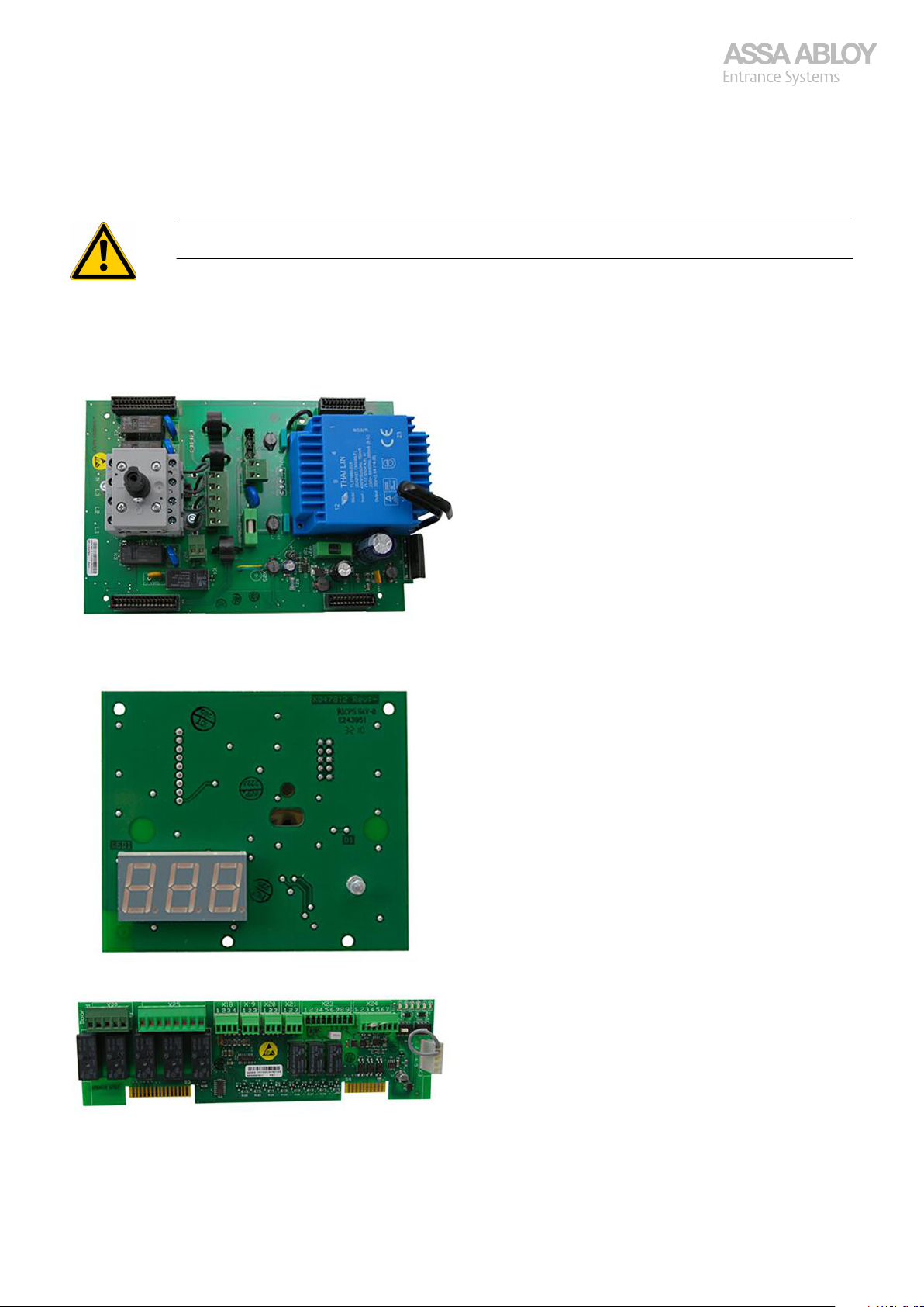
Configuration manual, installation and service
920-950 Docking
4
4.1
Basic board
950 Docking
Never connect/disconnect the Service tool without first disconnecting the power to the Control unit!
Unwanted commands may be activated. Check that automatic closing has not been activated by mistake!
950D Component denomination
Display board
Door board
950 Docking 51
Page 52
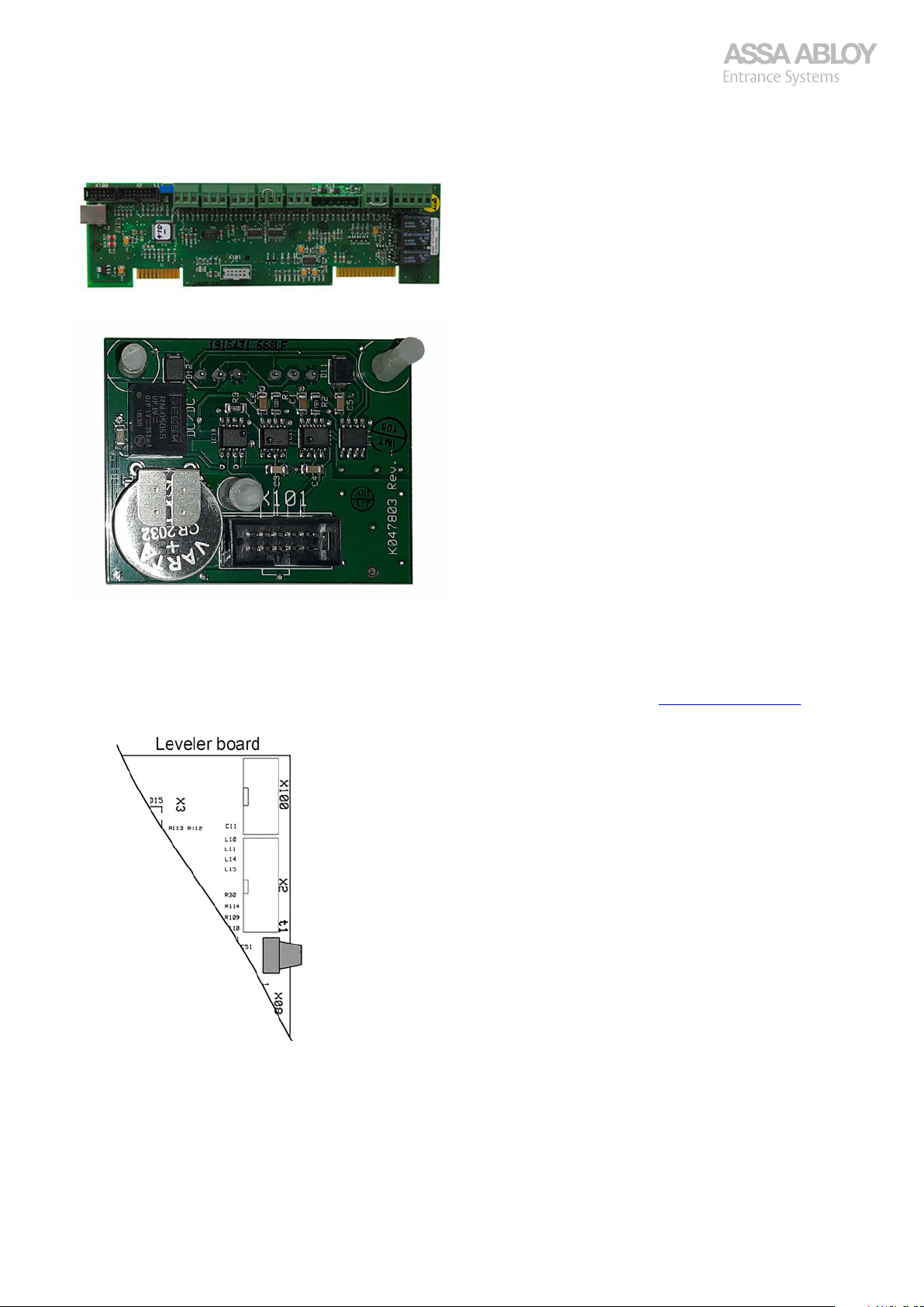
Configuration manual, installation and service
920-950 Docking
Leveler board
Network board
4.2
As a tool for certified service and installation staff, the Service tool is connected to connector X2 in the control box.
To avoid auto exit of menus set d0A to 1. Get familiar with the service tool buttons, see section 2. Service Tool Buttons
on page 7.
·
·
·
·
·
Configuration and error reading, 950D leveler, shelter, and door
The current error code is displayed for errors that triggers an error code. If several error codes exist at the same time, the
display alternates between the existing error codes
The Service tool can display the 15 latest errors from the leveler and 15 latest errors from the door.
By default, the state of the leveler, shelter, or the door is displayed on the control box and on the display of the Service
tool.
A dot in the lower right corner of the display indicates that the automatic closing is activated.
A dot after the first digit of the display indicates an IoT-DMS connection. Flashing light when searching and steady light
when connected.
950 Docking 52
Page 53
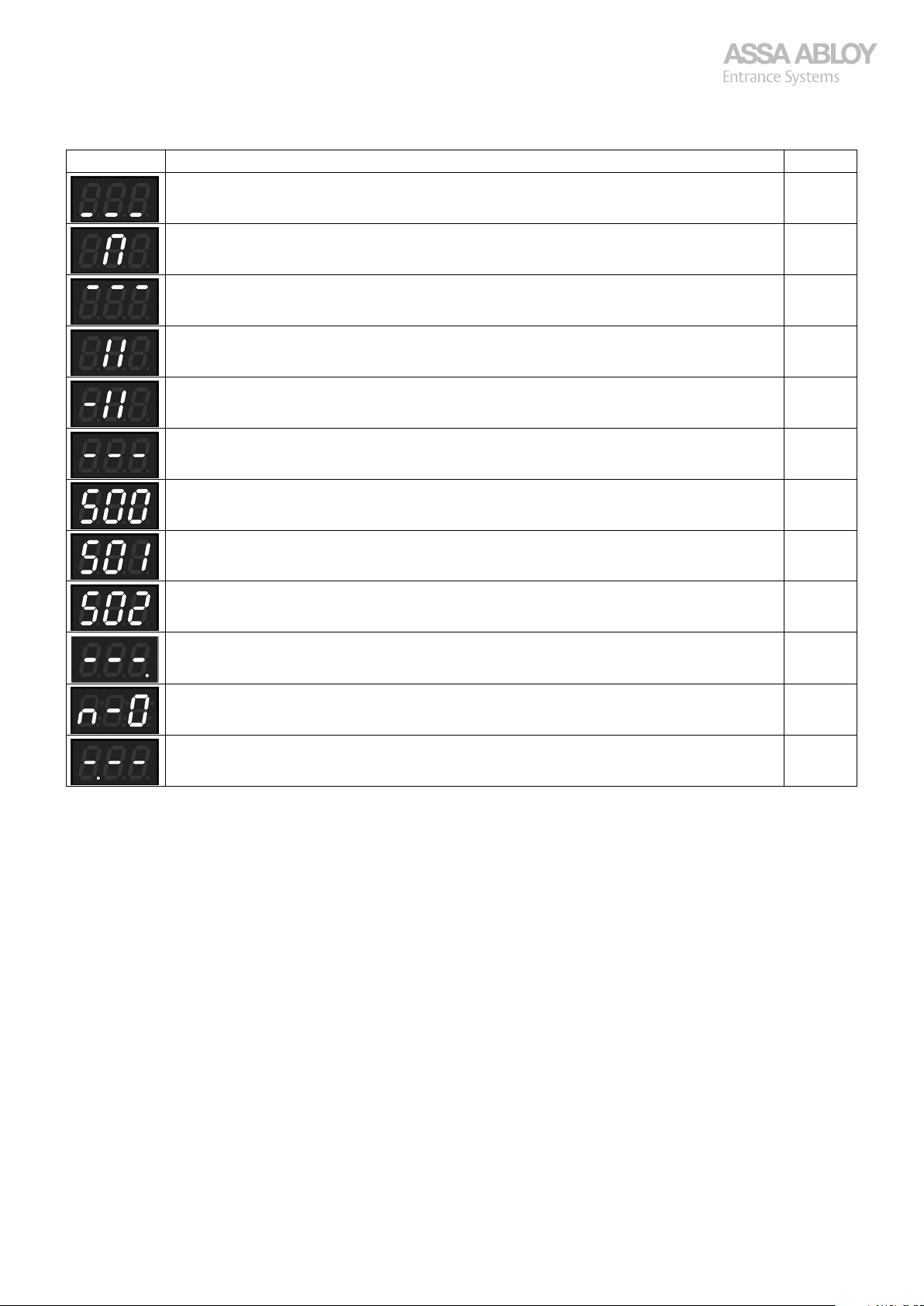
Configuration manual, installation and service
920-950 Docking
Display Explanation SW
Indicating leveler in resting position, closed door (CDM9 or S9 sensor) and shelter off. All
Flashing when shelter starts until door is open. All
Indicating opened door (CDM9 or S9 sensor). All
Indicating dock leveler lifts. All
Indicating extend swing lip or telescopic lip. All
Indicating leveler in floating position and/or door in unknown or intermediate position. All
Winter mode.
The shelter function is activated.
Summer mode.
The shelter function is not activated.
Truck in position. All
Indicating Auto close of the door. Flashing during countdown. All
Control unit buttons locked. Activated by X20, DMS or menu choice. All
Indicating IoT-DMS connection. Flashing when searching for connection. 043-
4.2.1
1.
Push BUTTON 1 repeatedly to browse through menu options [L] (leveler), [S] (shelter), and [d] (door).
2.
Push BUTTON 2 to enter the submenu that is displayed.
See Table 1 Submenu choice [d] for door submenu.
See Table 2 Submenu choice [L] for leveler submenu.
See Table 3 Submenu choice [S] for shelter submenu.
Entering the menu system
-026
-026
4.2.2
If the set Service interval is reached, either in operating time or in number of cycles, the SERVICE INDICATOR on the control
box will be lit. The light remains lit until the service counters are reset. By setting the service interval limit to zero (0) the
indication of time to service is disabled.
950 Docking 53
Indication of time for service
Page 54
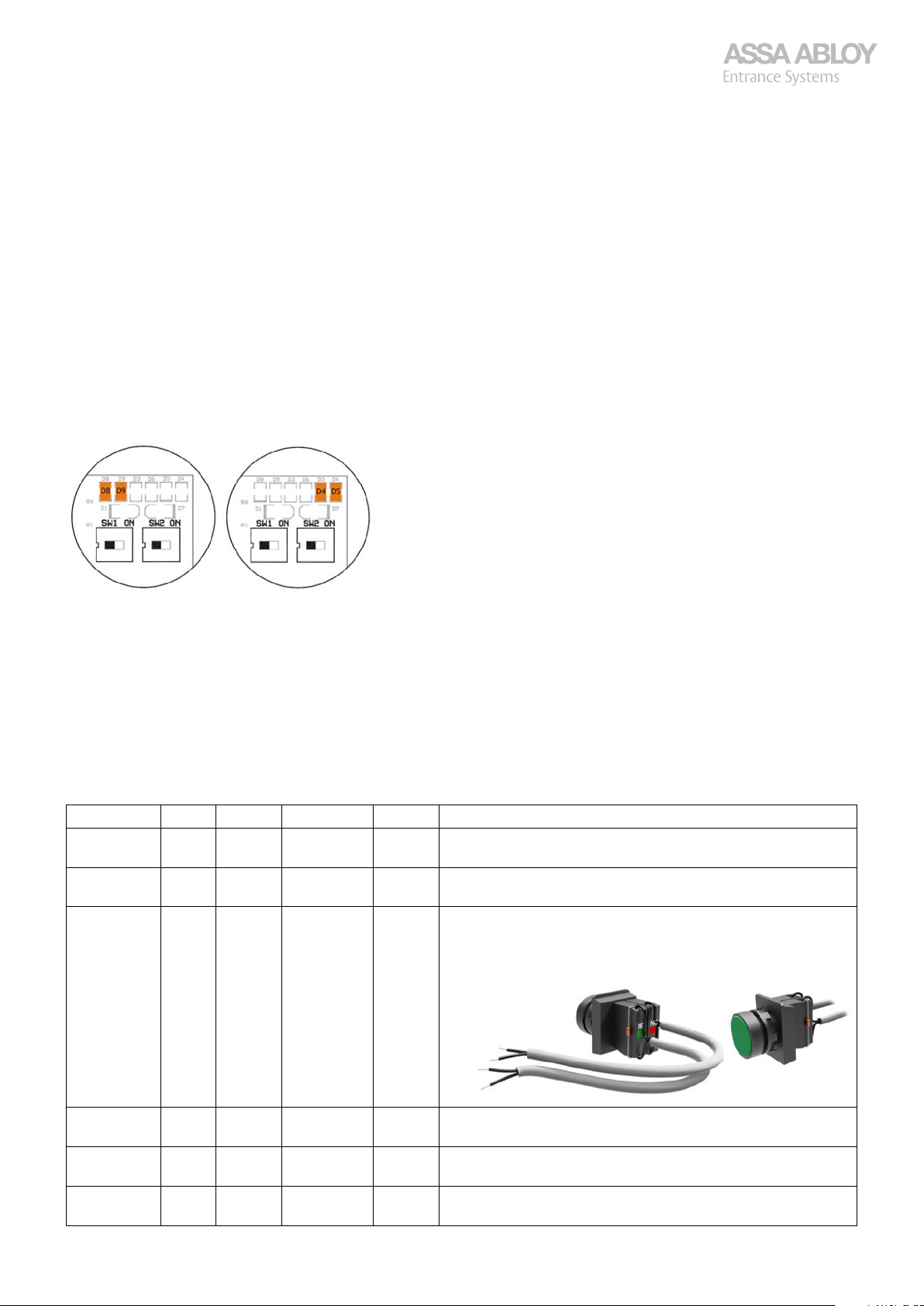
Configuration manual, installation and service
920-950 Docking
4.2.3
The display consists of only three digits. When there are more than three numbers to show, the display will scroll from right to
left.
Example
Total number of cycles 123456, display displays; 123, then 234, then 345 and finally 456.
4.3
4.3.1
Always check that:
The motor is properly fastened!
·
The floor is clean under the doors edge!
·
The buffers are correctly placed and fastened!
·
Motor Types:
STD, CDM9 for Over head sectional doors -400 kg 0,25 m/s.
·
2H, CDM9 for Over head sectional doors -250 kg 0,5 m/s.
·
HD, CDM9 for Over head sectional doors 400-800 kg 0,18 m/s.
·
Safety:
HTR, Hold-to-Run, no Safety device!
·
PNE, Pneumatic (Air activated) Rubber edge.
·
Control:
950, Display, Configurable Inputs/Outputs etc.
·
Limitations of the display
CDM9 - 950D installation procedure
950 Docking ( 950D) controller
Step Safety Control Motor Type SW Description
1. HTR,
PNE
2. HTR,
PNE
3.
Optional
4. HTR,
5. HTR,
6. HTR,
950 Docking 54
HTR 950D STD, 2H, HD -A16 Connect the temporary installation tool to X24:6-7.
PNE
PNE
PNE
950D STD, 2H, HD All Make sure the door is in closed position.
950D STD, 2H, HD All Disconnect the power supply.
950D STD, 2H, HD All Make sure dip switches SW1 and SW2 are in OFF position.
950D STD, 2H, HD All Pull the green ball to disengage the operator.
950D STD, 2H, HD All Manually pull the door open to 1.5 m above the floor.
·
·
·
From software version A10 and later use the N.C. contact,
·
for earlier software versions the N.O. contact with diode can
be used.
·
·
·
Page 55
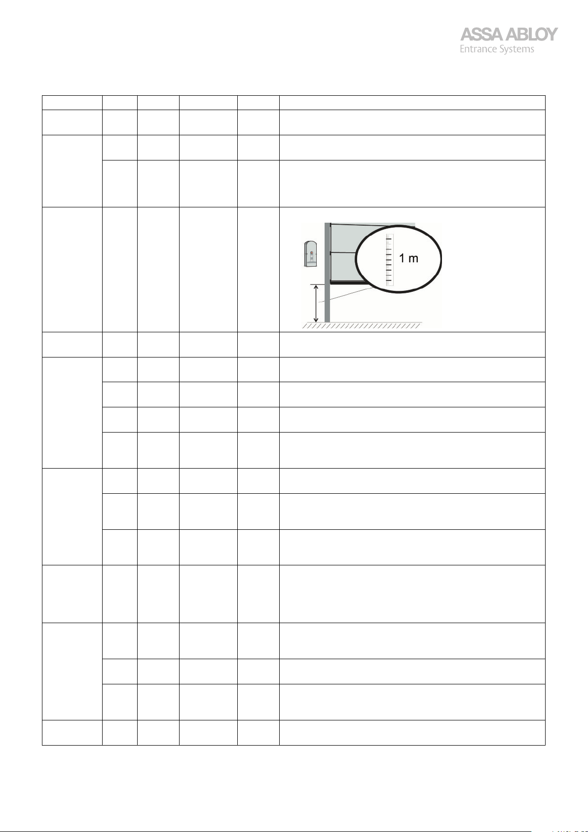
Configuration manual, installation and service
920-950 Docking
Step Safety Control Motor Type SW Description
7. HTR,
PNE
8. HTR,
PNE
HTR,
PNE
9. HTR,
PNE
950D STD, 2H, HD All Pull the red ball to engage the operator.
950D STD, 2H, HD All Pull/Push the door down until the operator gets into gear
950D STD, 2H, HD A17- Reconnect the power supply.
950D STD, 2H, HD All Mark the door track 1 m above the floor.
·
·
·
·
·
(click).
Push the CLOSE-button to jog the motor to engage.
Only one jog per 3 seconds. Convenient if the door is open
high.
10. HTR,
PNE
11.
Optional Torque
Setting
12. HTR,
13. HTR,
14. HTR 950D STD, 2H, HD -A16 Push the installation button to store the turning direction of
15. HTR,
HTR,
PNE
HTR,
PNE
HTR,
PNE
HTR,
PNE
PNE
All 950D 2H A19- Open Input X24:4-5 while toggle dip switch SW1 to ON to
All 950D HD A19- Open Input X24:4-5 and push CLOSE while toggle dip switch
PNE
All 950D STD, 2H, HD A17- STOP button method, open circuit X24:4-5 for one second
PNE 950D STD, 2H, HD All Push the bottom rubber to store the turning direction of
PNE
950D STD, 2H, HD All Reconnect the power supply.
950D STD, 2H, HD All Toggle the dip switch SW2 to ON to enter the torque setting
950D STD, 2H, HD All To increase the torque, push the OPEN button.
950D STD, 2H, HD All Push and hold the OPEN and CLOSE-buttons at the same
950D STD, 2H, HD All Toggle the dip switch SW2 to OFF to exit the torque-setting
950D STD, 2H, HD All Toggle the dip switch SW1 to ON to enable the installation
950D STD, 2H, HD All Push the OPEN or the CLOSE button until the bottom edge
950D STD, 2H, HD All Push the CLOSE button to close the door.
·
·
mode.
·
To decrease the torque, push the CLOSE button.
·
·
time for 3 seconds. The new torque value is now stored.
·
mode.
Note: Do not switch off the power again!
·
mode of the operator.
·
enable the 2H installation mode of the operator, then put
the X24:4-5 back again.
·
SW1 to ON to enable the HD installation mode of the operator, then put the X24:4-5 back again.
·
of the door is at the 1 m position, to determine the turning
direction of the operator according to which way it is installed.
Adjust with the OPEN and the CLOSE buttons if necessary.
·
·
the operator.
Make sure that the LEDs D4 and D5 dim for a short period.
·
·
to store the turning direction.
·
the operator.
Make sure that the LEDs D4 and D5 dim for a short period.
·
·
950 Docking 55
Page 56
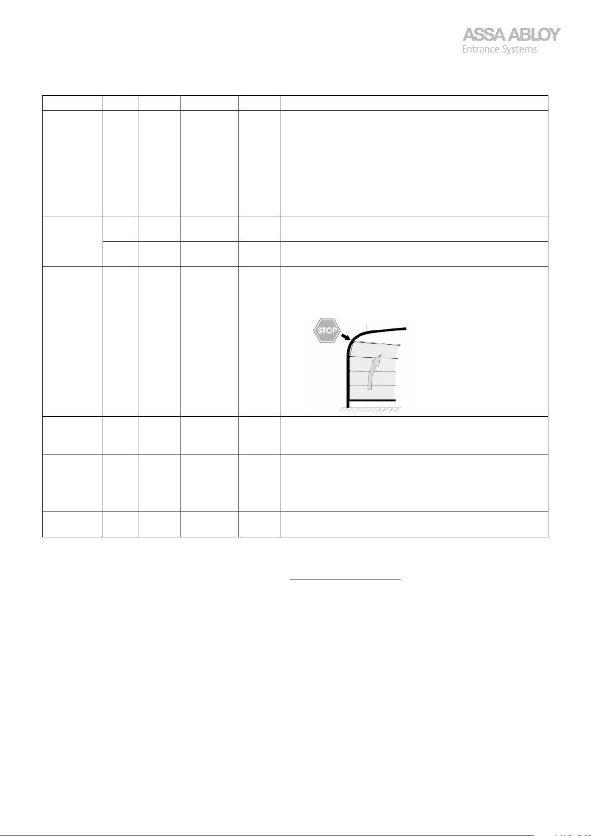
Configuration manual, installation and service
920-950 Docking
Step Safety Control Motor Type SW Description
16.
Optional
17. HTR 950D STD, 2H, HD -A16 Push the installation button to reverse the door as soon as
18. HTR,
PNE 950D STD, 2H, HD All If photocells are installed in rails (connected on X03:1-2):
Push the STOP button before the door is blocking the pho-
·
tocell installed in the rails.
Push the CLOSE button again to fully close the door.
·
The system ignores the photocells as a safety pulse below
the installed height. The photocell must be activated on the
way down, towards the floor, otherwise the door stays on
the floor and the installation will not complete.
Note: Max activation height 300 mm from the floor!
·
the door reaches the floor.
PNE,
HTR
PNE
950D STD, 2H, HD A17- The door automatically reverses as soon as the door reaches
950D STD, 2H, HD All If the door has track bend:
·
the floor.
Push the OPEN-button (to activate STOP) when the top roll-
·
er is in the middle of the bend.
Push the OPEN-button again.
·
19.
Optional
20.
Optional
21. HTR,
Verify Motor type in menu d10.
If E05/E24 is displayed after the installation procedure, redo the procedure from the beginning!
If the error remains, perform the troubleshooting, see section 3.15. Troubleshooting steps on page 37.
HTR,
PNE
All 950D STD, 2H, HD All For hold-to-run Open and/or Close, open X24:4-5 within 2 s
PNE
950D STD, 2H, HD All If the installation fails due to a too weak motor;
Check the balancing of the door and increase the torque by
·
following step Optional Torque setting in this table.
·
from door has reached open position.
Push OPEN for hold-to-run Open (1 second), and/or CLOSE
·
for hold-to-run Close (1 second), close X24:4-5 again.
To deactivate, redo the door installation from the beginning.
·
950D STD, 2H, HD All When door has reached top position, wait 3-4 s then dis-
·
connect eventual Installation tool and set SW1 to OFF.
950 Docking 56
Page 57
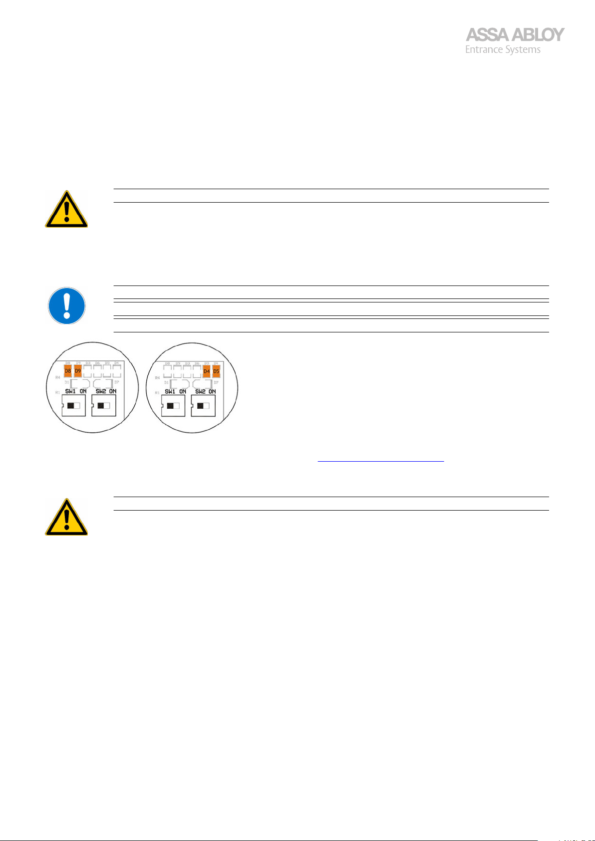
Configuration manual, installation and service
920-950 Docking
4.3.1.1
1.
Make sure the closing door reverses to fully open position when:
·
·
·
2.
Push the OPEN-button to start opening the door and try to stop the door by grabbing the handle to test the overload
safety stop. Max 40 kg lifting allowed. If the door is too strong or weak, adjust the torque and try again.
3.
Make sure all control devices are operational.
4.
Make sure the two yellow LEDs, D4 and D5 (Door board) switch off during two-three seconds when the door reaches the
floor.
If the LEDs switch off for no longer than 0.5 second, restart at step 1 to check the safety devices.
Test and adjustment, 950D
The safety edge is actuated.
A safety photocell beam is interrupted.
The operator is overloaded (max. excess force is 400 N (40 kg)).
Release the handle before you are lifted by the door, do not attempt to go up with the door.
If the LEDs D8 and D9 on the door board are lit, the stop circuit is ok.
A power cycle does not affect the programmed installation and settings.
After a power cycle the first closing cycle will only work in hold-to-run.
To regain impulse operation down make sure to open the door to fully open position to reset the impulse down operation.
If an error occurs, perform an electrical troubleshooting, see section 3.14. Electrical troubleshooting on page 33.
4.3.2
Automatic closing
Only allowed with Safety photocell!
950 Docking 57
Page 58
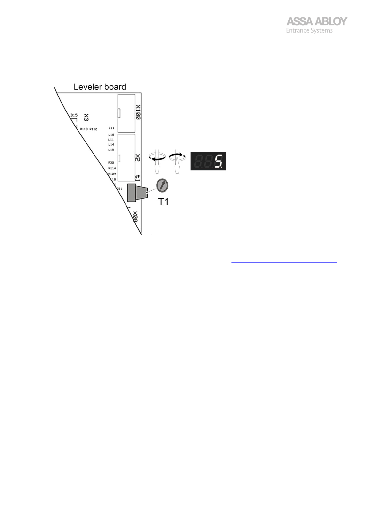
Configuration manual, installation and service
920-950 Docking
4.3.2.1
1.
Turn T1 clockwise with a small screwdriver until a number (5 to 30) is displayed.
2.
Fine adjust T1 until wished time setting for a start is set, before closing movement. A lit dot in the lower right corner of
the display indicates that the automatic closing function is activated. The dot flashes when the time is counting down for
the automatic closing.
For T2, pre-flashing, consult the 950D functions in the door menu, see section 4.5. Functions in the Door menu, submenu
choice [d] on page 59.
Automatic closing only possible from fully open door, triggering after passing photocell not possible, as of SW 053
possible with L45.
Activating Automatic closing
4.3.2.2
To adjust the automatic closing:
1.
Operate the door to the fully open position.
2.
Check that the door starts the closing action after the set time.
Potentiometer T1
Adjustable time between 5 and 30 min (5-300 s possible via SERVICE TOOL menu d0F).
If another down command is given during the countdown for automatic closing, the door closes immediately.
If up, stop, additional safety, safety edge or the safety photocell are activated during the closing time countdown, the
countdown starts from the beginning again.
The time can be changed at any time by changing T1.
4.3.2.3
To deactivate the automatic closing function:
1.
Turn T1 anti-clockwise with a small screwdriver until number 0 displays on the display.
The function is now deactivated.
4.4
The torque setting is available in 15 steps. Default factory setting is step 9. On the 950D control unit the torque setting is
displayed on the digital display (9). The ideal torque setting is as low as possible for safety reasons, so that the door does not
forcibly open or close when obstructed by people or objects. Max excess force is 400 N.
Time settings for Automatic closing
Deactivating Automatic closing
Torque setting CDM9 – 950D
950 Docking 58
Page 59
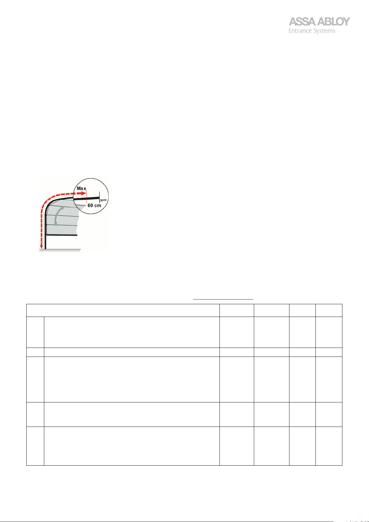
Configuration manual, installation and service
920-950 Docking
4.4.1
Only applicable for 950D.
1.
Stop the door in an half open position
2.
Set SW2 in the ON position.
3.
Make sure that SW1 is in the OFF position!
4.
Push OPEN-button once, for a stronger operator.
5.
Push CLOSE-button once, for a weaker operator.
6.
Push and hold the OPEN and CLOSE-buttons at the same time for 3 seconds.
The new torque value is now stored.
7.
Run the door by impulse operation to a fully open position.
8.
Run the door by impulse operation down.
The door reverses against the floor, runs up and stops with low speed against the buffers.
Push CLOSE-button to make sure learn was successful.
9.
Set the dip switch SW2 in the OFF position.
10.
The door is now ready for operation.
To evaluate the adjusted torque, operate the door within illustrated area.
11.
Torque adjustment after installation
4.5
The table below lists the menu choices available for SW1 and SW2, the function of BUTTON 1 and if it is possible to store
values in the internal memory within the menu. The function of BUTTON 1 is different in the different menus.
For menu and errors related to door procedure details, see section 3. CDM9 Door Operator on page 10.
Functions – DOOR menu
d01 Displays time for automatic closing T1 (in seconds/minutes depend-
d02 Sets time for pre-flashing T2, 1 - 32 seconds. 10 +1 Yes All
d03 Displays the total number of door cycles (x1).
d04 Displays and resets the total number of door cycles (x1).
d05 Displays the total operating time (in 24 h days).
Functions in the Door menu, submenu choice [d]
Default BUTTON 1 Save SW
- - No All
ing on d0f).
Set by potentiometer T1 on the Leveler board.
Changes as the corresponding potentiometer turns.
- - No All
If the cycles are ≤100 it is possible to count up the cycle counter by
pushing BUTTON 1.
Displays total operating cycles and is read-only, if no changes are allowed.
Counter status saved every 2 hours.
- 0 Yes All
Resettable by BUTTON 1.
Counter status saved every 2 hours.
- +1 Yes All
If the operating time is 0 it is possible to increase the operating time
by pushing BUTTON 1, otherwise read-only.
Read-only, if no changes are allowed.
Counter status saved every 2 hours.
950 Docking 59
Page 60
Configuration manual, installation and service
920-950 Docking
Functions – DOOR menu
d06 Displays and resets the operating time (in 24 h days) since the last
reset.
Resettable by BUTTON 1.
Counter status saved every 2 hours.
d07 Sets the limit for the service indicator in number of door cycles
(x1000).
Service interval disabled when set to 0.
d08 Sets the limit for the service indicator in operating days.
Service interval disabled when set to 0.
d09 Displays the door error log with the most recent error first, E08 is
not stored in this log., see section 3.13.2. Error log, d09 on page 30
d0A Sets automatic exit from service menu after 30 seconds if BUTTON 1
or BUTTON 2 has not been pushed.
0 = Automatically exits the menu system after time-out.
1 = Automatically exits the menu system disabled.
Reset to zero (0) after a power break.
d0b Displays current torque step of CDM9 operator. - Refresh No All
d0C Displays the active door errors with highest priority first. - +1 No All
d0d Sets functionality of Auto close timer.
0 = Close the door and retracts the shelter.
1 = Close the door.
d0E Sets Door mode.
0 = Hold-to-run-down mode. Sets automatically L10 = U01.
NOTE!
Only to avoid displaying E04, when running hold-to-run without
Safety Device.
1 = Normal mode.
2 = External control unit. Full function on external inputs and outputs will not be possible! Automatic closing and safety photocell to
be solved in external control unit. Shelter only turns off on time not
by closed door.
d0F Selects functionality of door auto close interval T1.
0 = Door auto close timer 5-30 minutes is selected.
1 = Door auto close timer 5-300 seconds is selected.
d10 Displays full SW version number.
Display scrolls sideways by pushing BUTTON 1 to show version:
A xx-xx-xx, variant: Std, 2H, HD, FD or S, B xx-xx, L x-x-x-xx.
d11 Top position adjustment, in % of default distance to the top.
Range 0-300.
0 = Top position with buffers compressed as far as possible
300 = The door stops at a top position of 3* the default distance, enabling long buffers to be compressed in a suitable way.
d12 Time before door starts to move if electrical lock is active.
Time is expressed in tenths of seconds 5-20. (5 = 0.5 seconds).
d13 Locks the door settings d11 and d14 from being set to default dur-
ing reset by menu L99 and installation.
0 = Unlocked.
1 = Locked.
d14 Clutch release distance, in % of maximum distance that the door re-
verses after reaching fully closed position. Releases the clutch and
removes the mechanical tension in the gearbox to limit the force
needed to disengage the door.
Range 0-100.
Default BUTTON 1 Save SW
- 0 Yes All
20 +1 Yes All
365 +1 Yes All
- +1 Yes All
0 0/1 Yes All
1 +1 Yes All
1 +1 Yes All
0 +1 Yes All
- - No 043-
100 +1 Yes 043-
5 +1 Yes 044-
0 0/1 Yes 053-
45
(SW-A20)
35
(SW A21-)
+1 Yes 053-
950 Docking 60
Page 61
Configuration manual, installation and service
920-950 Docking
4.6
Submenu choice [L] for Levelers displays the functions available for BUTTON 1 and if it is possible to store values in the internal
memory within the menu. The function of BUTTON 1 is different in the different menus.
Functions - Leveler menu Default Button 1 Save SW
L01 Displays the Leveler error log with next error in order of priority and
L02 Displays the total number of leveler cycles (x1). Resettable by BUT-
L03 Displays the total number of leveler cycles (x1).
L04 Displays the total operating time (in 24h days).
L05 Displays the total operating time (in 24h days). Resettable by BUT-
L06 Sets a limit for SERVICE INDICATOR in number of leveler cycles
L07 Sets limit for SERVICE INDICATOR in operating time (in 24h days).
L08 Address of the control unit on DMS-network (1-255). 255 +1 Yes All
L09 DMS-Network baudrate.
L10 Auto return with one or two push on AUTO-button.
Functions in the Leveler menu, submenu choice [L]
- +1 Yes All
the most recent error first. When the error log has come to the end
(max number 15), END is displayed.
- 0 Yes All
TON 1.
Counter status saved every 2 hours.
- Refresh
If the cycles ≤100 it is possible to increase the cycle counter by
pushing BUTTON 1.
Counter status saved every 2 hours.
- Refresh
If the time ≤100 days it is possible to increase the cycle counter by
pushing BUTTON 1.
Counter status saved every 2 hours.
- 0 Yes All
TON 1.
Counter status saved every 2 hours.
3 +1 Yes All
(x1000).
Service interval disabled when set to 0.
365 +1 Yes All
Service interval disabled when set to 0.
38400 +1 Yes *043U00 = 38400 bps.
U01 = 187500 bps.
*U02 = Network Board set for IoT, from version 043-
U00 +1 Yes *044U00 = Leveler, door, and shelter returns.
U01 = Leveler return on first push, door, and shelter on second push.
*U02 = Door return on first push, leveler and shelter on second
push, from version 044-.
**U03 = Return button closes door to reduced position and then
the leveler can be operated (by pressing the auto button again).
No All
(+1)
No All
(+1)
**050-
950 Docking 61
Page 62
Configuration manual, installation and service
920-950 Docking
L11 External interlock of leveler (S9).
U00 = external switch to detect open door (default for standalone
levelers).
U01 = CDM9 to detect open door (default for versions with door
control).
U02 = CDM9 to detect open door (from a pre-selected door position). Will not work in Hold-to-run mode, before version 044.
Run the door to the wanted position go in and set L11 to U02.
*U03 = CDM9 to detect open door (from a pre-selected door posi-
tion), from version 044-.
Door will stop at pre-selected position and leveler can be operated.
Second push on OPEN button will open door to fully open position.
Run the door to the wanted position go in and set L11 to U03.
**U04 = CDM9 to detect open door (from a pre-selected door posi-
tion), from version 050-.
Door will stop at pre-selected position and only at this position can
the leveler be operated in any way.
Second push on OPEN button will open door to fully open position,
IF the leveler has been placed on the vehicle, otherwise the door can
not be opened further.
Run the door to the wanted position go in and set L11 to U04.
Default, U01, will give fully open door with CDM9, no U02 setting!
L12 Hydraulic pump motor current limit adjustment.
2.6 A
3.2 A
3.8 A
4.4 A
5.0 A
5.6 A
6.2 A
6.8 A
7.4 A
8.0 A
8.6 A
9.2 A
L13 Cross-traffic switch (S6) exists or not.
U00 = Cross traffic switch installed, no autoclose possible with leveler on truck.
U01 = No switch installed (door located behind leveler).
Auto close always possible.
U02 = Cross traffic switch installed, auto close always possible.
L14 Lift/swing lip extend timer 1 – 19 seconds. 5 +1 Yes All
L15 Swings lip fold in timer 5 – 20 seconds. 11 +1 Yes All
L16 Returns "lift" leveler timer 3 – 30 seconds. SD 5
L17 Teledock lip retracting time during lowering 0 – 2.0 seconds. 0 +0.1 Yes All
U00/U01 +1 Yes *044-
**050-
SD 4.4
TD 5.6
U01 +1 Yes All
TD 9
+1 Yes All
+1 Yes All
L18 Starts shelter - open door timer 0 – 30 seconds. 10 +1 Yes All
L19 Closes door – stop shelter timer 0 – 30 seconds. 30 +1 Yes All
L20 Service reset.
U00 = No change.
U01 = Resets all error lists and counters for leveler and door.
L21 Locks/unlocks control unit, see section 4.6.6. Lock/unlock of control
unit on page 67.
U00 = Unlocks control unit.
U01 = Locks control unit (a key is displayed).
950 Docking 62
- +1 Yes All
U00 +1 Yes All
Page 63
Configuration manual, installation and service
920-950 Docking
L22 Numbers of valves for Swingdock.
U00 = Default by variant detection in button panel on the lid.
U01 = Swings dock one valve function (overrides variant detection).
U02 = Swings dock two valves function (overrides variant detection).
L23 Input functionality for X18:2, see section 4.6.1. Configurable input
options,L23-25, L30-31, and L35-36 on page 64.
Default = Start shelter – open door.
Note!
U14 might be a better option!
L24 Input functionality for X18:3, see section 4.6.1. Configurable input
options,L23-25, L30-31, and L35-36 on page 64.
Default = Close door – stop shelter.
L25 Input functionality for X18:4, see section 4.6.1. Configurable input
options,L23-25, L30-31, and L35-36 on page 64.
Default = Door extra safety.
L26 Output functionality for K12, X25:1-2, see section 4.6.2. Configura-
ble output options L26-28 and L32 on page 66.
Default = Truck in position S15.
L27 Output functionality for K13, X25:3-4, see section 4.6.2. Configura-
ble output options L26-28 and L32 on page 66.
Default = Leveler in resting position S6.
L28 Output functionality for K14, X25:5-6, see section 4.6.2. Configura-
ble output options L26-28 and L32 on page 66.
Default = Electrical door lock output (DMS).
L29 Vehicle detection X10:1-2.
U00 = X10:1-2 active only if S02 is shown on the display.
U01 = X10:1-2 active is required to start shelter and open door.
Truck in position detection stays active if the shelter is on, even if
X10:1-2 input is lost. Only applicable for SW -050.
Truck in position detection will only be on if X10:1-2 is active! Applicable for SW 051-.
U02 = X10:1-2 active is required to start shelter.
Truck in position detection stays active if the shelter is on, even if
X10:1-2 input is lost. Only applicable for SW -050.
Optional output U05 follows this.
U03 = X10:1-2 active is required to open door.
L30 Select function on input X13:5, see section 4.6.1. Configurable input
options,L23-25, L30-31, and L35-36 on page 64.
Default = Auto close of door enabled/disabled.
L31 Select function on input X13:6, see section 4.6.1. Configurable input
options,L23-25, L30-31, and L35-36 on page 64.
Default = Close door (and a second activation while moving down
will not stop the door).
L32 The output functionality for K4, X07:1-2, see section 4.6.2. Configu-
rable output options L26-28 and L32 on page 66.
Default= Indication of open door.
L33 Delay timer for door closing after AUTO-return-button has been ac-
tivated and the leveler has reached free-floating position.
Can be set to max 10 seconds, in steps of 1, for instance with PHC in
rail, leveler may activate the PHC in rail.
L34 Avoids door damage from moving leveler, when door not fully en-
gaged.
U00 = No interlock of leveler with disengagement door (E11)
U01 = Interlock of leveler with disengagement (E11).
L35 Selects function on input X09:1-2, see section 4.6.1. Configurable
input options,L23-25, L30-31, and L35-36 on page 64.
Default = Leveler lip fully retracted indication.
U00 +1 Yes All
U00 +1 Yes All
U01 +1 Yes All
U04 +1 Yes All
U05 +1 Yes All
U04 +1 Yes All
U02 +1 Yes All
U00 +1 Yes All
U03 +1 Yes All
U15 +1 Yes *042-
U00 +1 Yes *043-
0 +1 Yes 043-
U00 +1 Yes 043-
U12 +1 Yes 044-
950 Docking 63
Page 64
Configuration manual, installation and service
920-950 Docking
L36 Selects function on input X12:1-2, see section 4.6.1. Configurable
input options,L23-25, L30-31, and L35-36 on page 64.
Default = Leveler in resting position indication.
L37 Photocell sabotage alarm timer. Can be set to 0-900 s.
Sets the time the photocell must stay active before a photocell sabotage alarm is indicated (to DMS/IoT and out on selectable output,
U19). When the photocell goes low, the signal will also go low.
L38 U00 = The selectable output Electrical door lock (U02) is only con-
trolled by DMS and selectable input U10 and U14.
U01 = The selectable output Electrical door lock (U02) is controlled
by all opening commands.
L39 Sets the selected output to LED on door over rs485 (OH1142P Dual
Drive), coordinate light pattern on door and on wall:
U00: No Led-on-door over rs485.
U01: Flashing light.
U02: Steady light.
U03: Not closed door.
U04: Not open door.
U05: Closed door.
L40 Timer 1-10 seconds for U25 (Teledock only). 1 +1 Yes 050-
L41 Delay time on gap warning and U20 optional output by X10-input
activation.
SW 050-052: Range 1-20 s.
SW 053-: Range 1-60 s.
L42 Timer before manually locking/unlocking when correct code is en-
tered., see section 4.6.6. Lock/unlock of control unit on page 67
Timer 0 – 999 sec.
Stores the number of seconds after the correct code is entered and
the control unit will toggle lock state.
L43 3-digit code to lock/unlock the control unit manually., see section
4.6.6. Lock/unlock of control unit on page 67
Code 0 – 999
If the value is 0 the lock/unlock sequence is blocked, since that is not
a valid code. The value 0 can be used for customers that do not want
to have the manual lock/unlock functionality.
L44 ECO-mode;
U00: (default) normal
U01: After 20 seconds at cross traffic position, the leveler will be stiff
and save energy (x kWh).
L45 Photo cell activation will start auto close:
U00: (default) no photo cell activation is needed to start auto close
to start down counting
U01: Photo cell activation is needed to start auto close (each time
the door is leaving the fully closed position).
L98 Displays network addresses (for DMS) on all units on the line.
U00 = OFF
U01 = ON
Can be turned ON or OFF on any unit on the line.
L99 Factory pre-setting for the control unit. Torque and total counters
excluded.
Change to U01 and save.
The functions are now as pre-set from factory.
U13 +1 Yes 044-
60 +1 Yes 050-
U00 +1 Yes 044-
U00 +1 Yes 050-
10 +1 Yes 050-
900 +1 Yes 052
0 +1 Yes 052
U00 +1 Yes 053-
U00 +1 Yes 053-
U00 +1 No All
- +1 Yes All
4.6.1
The SERVICE TOOL can be used to configure the different inputs and outputs to other functions, e.g. setting menu L23 to
option U01 will cause the X18:2 input to function as "Close door and stop shelter".
950 Docking 64
Configurable input options,L23-25, L30-31, and L35-36
Page 65
Configuration manual, installation and service
920-950 Docking
The table shows the values for all Input options found in service menus L23-L25, L30-L31, and L35-36. A door re-installation
does not change the configuration of inputs.
Setting Description SW
U00 Starts shelter- opens door. See also U14. All
U01 Closes door – stops shelter. All
U02 Starts shelter and opens door outside.
Works only if the leveler is in free-floating position.
U03 Auto close of door, enables/disables. All
U04 Door extra safety. All
U05 Closes door (overrides any U01 on L23-L25). All
U06 Opens door, open in the lid disabled. All
U07 Open door position indication (ex. door control unit d0E=2) All
U08 Closed door position indication (ex. door control unit d0E=2) All
U09 Disables CLOSE/AUTO button 043U10 OPEN or CLOSE/AUTO
Disables OPEN and CLOSE/AUTO buttons.
This function is also active at torque adjustment and installation mode, SW 1 and/or 2 ON.
U11 Error indication from external control box (F16), active low. 044U12 Leveler lip fully retracted indication. 044U13 Leveler in resting position indication. 044U14 Opens door, a second activation does not stop the door while moving up. 044U15 Closes door, a second activation does not stop the door while moving down. 044U16 SafeGap button. 053U17 SafeGap lip indicator. 053U18 SafeGap alarm sensor. 053All Only one optional input is valid at the same time, not two or more inputs with the same function. -044
All
043-
950 Docking 65
Page 66
Configuration manual, installation and service
920-950 Docking
4.6.2
The SERVICE TOOL can be used to configure the different inputs and outputs to other functions, e.g. setting menu L26 to
option U01 will cause the X25:1-2 output to function as "Indication of closed door".
The table shows the service tool values for all output options found in service menus L26-L28 and L32. A door re-installation
does not change the configuration of outputs.
Setting Description SW
U00 Indication of open door. All
U01 Indication of closed door. All
U02 Electrical door lock output (DMS). Delay before the door open by d12. Control conditions by L38. All
U03 Flashing light. All
U04 Leveler in resting position S6. All
U05 Truck in position S15. All
U06 French light. All
U07 Error indication, (except E08), the output is OFF (open) when one or more errors are active, other-
U08 Steady light. All
U09 Not open door. All
U10 Not closed door. All
U11 The output is ON when leveler is in Resting, Lift, or Auto Return mode. When leveler has been in
U12 Reservation light, Reserved for DMS All
U13 Aux 1, DMS All
U14 Loading light – outside. DMS-controlled. All
U15 Loading light – inside. DMS-controlled. All
U16 Vehicle release. Output is switched ON when the door and shelter is closed and truck is in position.
U17 Leveler in free-floating position, loading. 043U18 Wheel chock is in position (X11:1-2). 043U19 Additional safety photocell for the door (X03:1-2) is activated. 043U20 Truck left without withdrawing the leveler. Time delay via L41. 044U21 Loading completed, output is active for 30 seconds when X15:5 is activated. 044U22 Actives while leveler is retracted by AUTO-button to resting position. 044U23 Auto close activated, T1>0. 044U24 Vehicle release Dock-In 2.0, Output is switched ON for 500 ms when the door & shelter is closed and
U25 Gap warning. Output is on if if the door is open and the lip of the leveler has not been extend for a
U25 Gap warning. Output is on if the door has started to open and the lip of the leveler has not been
U26 SafeGap button active. 053U27 Shelter active (has a delay on 10s when shelter turns off). 053All Only Only one optional Output is valid at the same time, not two or more outputs with the same
Configurable output options L26-28 and L32
All
wise ON (closed).
All
Floating mode for 9 seconds the output is set to OFF.
All
If an activator is used on terminal X11 (Wheel Chock) at the start of the docking process, the activator will also be included in this function.
050the truck is in position.
If an activator is used on terminal X11 (Wheel Chock) at the start of the docking process, the activator will also be included in this function.
050longer time than specified in menu [L40] (in seconds). If the truck leaves while the leveler is used,
the output will be on again. It can only be cleared by either returning the truck or returning the leveler to resting position. (Teledock only)
053extend for a longer time than specified in menu [L40] (in seconds). If the vehicle leaves while the
leveler is used, the output will be on again. It can only be cleared by either returning the leveler onto
the vehicle or returning the leveler to resting position and close the door completely. (Teledock only)
All
function.
950 Docking 66
Page 67
Configuration manual, installation and service
920-950 Docking
4.6.3
1.
Connect the Service tool to connector X2 on the Leveler board.
2.
Push BUTTON 1, to display menu [L].
3.
Push BUTTON 2 to enter Leveler submenu; L01 is displayed.
4.
Push BUTTON 2 to enter the submenu. The latest error in the log (e.g., F11) is displayed.
If there are no errors "End" is displayed.
5.
Push BUTTON 1 to see next error codes. If there are no more error codes, the display displays "End".
6.
Push BUTTON 2 to leave the menu.
7.
Push BUTTON 1 until [L] is displayed.
8.
Push BUTTON 1 three times, alternatively push BUTTON 1 continuously for 2 seconds, to exit the service menu.
9.
The display now goes back to normal operation showing the state of the leveler, shelter, or the door. Alternatively, the
active error codes are displayed.
4.6.4
1.
Push BUTTON 1 to go to menu L01.
2.
Push BUTTON 2 to enter menu L01.
3.
Push BUTTON 2 and then BUTTON 1, keep the buttons pushed at the same time for a couple of seconds.
4.
Release the buttons, the message "End" is displayed.
The error log is erased, and the change is saved.
4.6.5
A combination of L10 U03, L11 U03/U04, L40 (1-10s), L26/27/28/32 U25 and vehicle detection on input X10, adjustable by
L41. As of software 050.
Example, L01 – Error Log
Example, Error Log Reset
Safe loading and gap warning (Teledockonly)
U25 and L40 are valid for Teledocks ONLY!
Works with the door in impulse AND hold-to-run mode for closing!
L11 U03/U04 sets the reduced open position that stops the doors at L10 U03, sets the logic, L26/27/28 and gives a closed
contact for warning.
Load house in resting position, activates Open, warning goes on, door stops at the L11 U03 position. The leveler can be
operated and automatic closing is possible.
With L11 at U04 running the leveler is locked totally to this position, not possible to run the leveler with the
door in any other position, if the leveler has not been operated, then one can’t open the door fully, you can
always close the door fully.
Once the leveler has been operated, automatic closing is no longer possible at the L11 U03 position.
Warning stays on until the lip has been extended at least as long as L40. Once this is achieved, the leveler is in free-floating
position on the vehicle, the door opens to fully open position. Automatic closing is now possible and warning is off
If the leveler is adjusted (only possible with L11 at U03), warning is on again. To retract the lip a little bit, it actually needs to
retracted too much first and then extend it as long as L40 again to clear the warning.
Press Auto once the loading and unloading is finished. The door closes to the L11 U03/04 position, automatic closing is
·
possible and warning is off.
Press Auto again, the leveler is returned to cross traffic position, warning goes on. Automatic closing is now possible.
·
Close the door with a third activation of Auto, the door closes, and warning goes off at closed door.
·
A vehicle leaving during on/off-loading can be detected via input X10 and the gap warning is then triggered again. The time for
this is adjustable, 1-20 s via L41. Works with the door in impulse AND hold-to-run mode for closing!
4.6.6
The control unit can be locked/unlocked with menu L21, IoT/DMS and with the following sequence:
Push and hold the CLOSE/AUTO-button for 60 seconds when the door is fully closed.
Release the CLOSE/AUTO-button when the key symbol starts to flash "n-0".
The display shows 0. To increase the value by one push the UP-button. Hold the UP-button to make the counting faster.
If there is no activity for 60 seconds, the display goes back to normal state and the sequence needs to be restarted.
950 Docking 67
Lock/unlock of control unit
Page 68
Configuration manual, installation and service
920-950 Docking
Confirm the correct 3-digit code by first pressing the CLOSE/AUTO-button and simultaneously holding the UP-button.
If the 3-digit code is the same as stored in menu L43, the display will start to down count in seconds what has been set in the
menu L42. Otherwise, the lock/unlock sequence is aborted, and the control unit will return to the state before the lock/unlock
sequence was initiated. When the timer reaches 0, the door will toggle the lock status of the control unit, L21.
4.7
Submenu choice [S] for Shelter displays the functions available for BUTTON 1 and if it is possible to store values in the internal
memory within the menu. The function of BUTTON 1 is different in the different menus.
Functions – Shelter menu Default BUTTON 1 Save SW
S01 Displays the total number of shelter cycles (x1).
S02 Shelter type.
4.7.1
Not valid after SW 026
Function to Winter mode, shelter function enabled:
1.
2.
3.
4.7.2
Functions in the Shelter menu, submenu choice [S]
- +1 Yes All
If the cycles are ≤100 it is possible to increase the cycle counter by
pushing BUTTON 1.
Read-only, if no changes are allowed.
Counter status saved every 2 hours.
U00 +1 Yes All
U00 = SIR.
U01 = SIB / SIE.
Example, Select summer function
The leveler in resting position, door closed, and the shelter switched off.
Push the AUTO-button for 5 seconds
If summer mode is active the display flashes S00.
Push the OPEN DOOR-button, [S00] is displayed for 2 seconds and winter mode is selected.
Example, Select winter function
Not valid after SW 026
Function to Summer mode, shelter function disabled:
1.
The leveler in resting position, door closed, and the shelter switched off.
2.
Push AUTO-button for 5 seconds If winter mode is active display flashes S01.
3.
Push OPEN DOOR-button, [S01] is displayed for 2 seconds and summer. mode is selected.
The display on the Service tool displays the state of the leveler, shelter or the door.
4.
Push BUTTON 1 two times to display menu [S].
5.
Push BUTTON 2 to enter Shelter submenu, S01 is displayed.
4.8
4.8.1
Resets all error lists (leveler and door) and all service counters (time and cycles for leveler and door). The display displays the
state of the leveler, shelter or the door.
1.
2.
3.
4.
5.
6.
7.
8.
Service reset 950D
L20 - Total service reset (Leveler and door)
Push BUTTON 1, menu [L] is displayed.
Push BUTTON 2 to enter Leveler submenu, L01 is displayed.
Push BUTTON 1 repeatedly until submenu L20.
Push BUTTON 2 to enter the submenu, the display now displays U00.
Push the BUTTON 1, U01 is displayed.
To leave the menu without saving the new value push BUTTON 2.
To leave the menu and save the value, keep BUTTON 2 pushed while pushing BUTTON 1.
Push BUTTON 1 repeatedly until [L] is displayed, push BUTTON 1 three more times to exit from service menu.
Alternatively push BUTTON 1 continuously for 2 seconds to exit from service menu.
The display is back to normal operation, showing the state of the leveler, shelter, or the door.
950 Docking 68
Page 69
Configuration manual, installation and service
920-950 Docking
4.9
4.9.1
After control system start; display and service LED does not lit.
Cause Solution
The display and service LED does not lit after
system start.
Operate the door for a while and check all functions.
4.9.2
Troubleshooting steps Control unit
Follow each step in the table. If the problem on the row is not applicable, continue with the next row. The
whole table must be checked from top to bottom.
Start over from the top of the trouble shooting if something has been replaced.
Display and service LED does not lit
Check 230V / 400V supply voltage at mains isolator or terminal X01
·
(when emergency stop button).
Check fuses F1 and F2 with an ohm-meter.
·
Check the connection of ribbon cable to display board.
·
Check control voltage 24 VDC at plug connector X08 pin 1(+) and 3(-)
·
on the leveler board.
If the supply voltage and fuses are OK, but no 24 VDC on X08, the basic
·
board is defect, replace the basic board.
If the supply voltage, fuses and 24 VDC are OK, the leveler board is de-
·
fect, replace the leveler board.
Service indicator illuminates
Service indicator illuminates.
Cause Solution
The limit for cycle counter or duty timer for leveler or door has been reached.
Operate the door for a while and check all functions.
4.9.3
Service indicator flashes.
Cause Solution
Power or emergency has been turned off / on. Reset by running the leveler.
Operate the door for a while and check all functions.
4.9.4
The display shows a key.
Service indicator flashes
Display shows a key
Perform service on the leveler or/and door.
·
Enter service reset in menu L20 in the service tool. This will also reset
·
the error list for both leveler and door.
Reset the Leveler service counter by menu L02 and the leveler operat-
·
ing time by menu L05 in the service tool, reset the error list by the
service tool in menu L01.
Reset the Door service counter by menu d04 and the Door operating
·
time by menu d06 in the service tool.
Reset the error list by the service tool in menu d09.
·
·
Cause Solution
Control unit is locked for all functions. The control unit can be locked for all functions by the lock bolt switch
950 Docking 69
·
(X20:1-2 NO), by setting L21 to U01 with the Service tool (U00 to unlock) or by a lock command from CMS network. The display will show
a key.
Page 70
Configuration manual, installation and service
920-950 Docking
Operate the door for a while and check all functions.
4.10
4.10.1
Door does not reverse on the floor during installation.
Cause Solution
Torque too low. Adjust torque.
Photocell in rail installation activated. Reinstall without photocell in rail activated.
Bad signal from the PNE safety edge, a lot of
very short signals instead of one signal, at least
150 ms. Does not always show on D4-D5.
The cables from the electric motor to the power PCB are switched, wrong order.
Operate the door for a while and check all functions.
For information on error codes for the door, see section 3.16. Indication of errors (E) on page 46.
Troubleshooting steps Door
Follow each step in the table. If the problem on the row is not applicable, continue with the next row. The
whole table must be checked from top to bottom.
Start over from the top of the trouble shooting if something has been replaced.
Door does not reverse during installation
·
·
Make sure the photocells are activated before the door reaches the
·
floor, see section 3.7. CDM9 Installation on page 15.
Check and adjust the bottom sealing, the PNE safety edge, and the
·
hose.
Install the door without PNE safety edge in order to isolate the prob-
·
lem, see section 3.7. CDM9 Installation on page 15.
Replace the broken parts of the PNE safety edge.
·
Make sure the cables are correctly connected. See color markings on
·
the PWR-board.
Replace the A-processor board.
·
4.10.2
The door does not start to open or close.
Cause Solution
The push button is installed but the door does
not start to open or close.
No 24 VAC between X23:2 and 7 on door
board.
No 24 VAC between X23:6 and 7 on door
board.
Automatic fuse on the A-processor board activated.
No 24 VAC between X24:2 – X23:7 on door
board.
No 24 VAC between X24:4 – X23:7 on door
board.
Voltage more than 0 VDC between X2:1 – X2:9
on the Display board when Open button is
pressed and 5 VDC if not pressed.
Door neither starts to open nor close
Disconnect all push button units.
·
Make sure the mechanical unit is engaged.
·
Check that the fuse for the main electrical supply.
·
Check the 230 VAC supply voltage to CDM9 at terminal X02 on the ba-
·
sic board.
Check that the mechanical unit is in normal mode (not installation
·
mode).
Check the stop circuit (jumper or external stop X24:4-5 on door
·
board, jumper or emergency stop in lid X06:1-3 on basic board).
Check that there are two jumpers connected to X24:1-2-3 on door
·
board.
Check that the torque adjustment switch SW2 on the door board is
·
off.
Check the mains and control cables.
·
Make sure no short-circuit has activated the automatic fuse for 24 VAC
·
on the A-processor board.
Replace the A-processor board.
·
Replace the door board in the control unit.
·
Replace the door board in the control unit.
·
Replace the lid of the control box.
·
950 Docking 70
Page 71
Configuration manual, installation and service
920-950 Docking
Cause Solution
Installation switch set to OFF. Set installation switch ON.
Re-program the operator.
Operate the door for a while and check all functions.
For information on error codes for the door, see section 3.16. Indication of errors (E) on page 46.
·
Make sure there is 24 VAC between X23:1 – X23:7 on door board
·
when Open button is pressed.
Check the ribbon cable, the leveler and the display board for damage.
·
Replace the door board in the control unit.
·
4.10.3
The door does not close when Close/Auto button is pressed.
Cause Solution
Photocell amplifier present on X3:1 – 2 on door
board and no 24 VAC between X23:5 and 7 on
door board.
The leveler is equipped with a cross-traffic sensor connected to X12 on Leveler board.
The leveler is not equipped with a cross-traffic
sensor.
External equipment is connected to X18:4 on
door board. The selectable input X18:4 [L25] is
by default set as extra safety.
Voltage more than 0 VDC between X2:4 – X2:9
on the display board when Close/Auto button is
pressed and 5 VDC if not pressed.
Set installation switch SW1 on the door board
to ON.
Re-program the operator.
Door does not close when Close/Auto button is pressed
Remove the photocell amplifier and install a bridge between X3:1 -
·
X3:2.
Make sure there is 24 VAC between X23:4– X23:7.
·
Make sure there is 24 VAC between X23:5– X23:7
·
Examine the photocell circuit for damage.
·
If no 24 VAC is not present, replace the door board in the control unit.
·
Make sure there is 24 VDC between X12:2 and 3 on leveler board
·
when leveler is in resting position.
Check the connection of cable to and adjustment of cross-traffic posi-
·
tion sensor S6.
Check correct setting in menu L13 with the service tool.
·
Select correct function, alternatively check the connected equipment,
·
shall be a normally open contact.
Replace the lid of the control box.
·
Make sure there is 24 VAC between X23:3 – X23:7 on door board
·
when Close/Auto button is pressed. If not, replace Door board in the
control unit.
Note: The Ribbon cable, Leveler and/or display board may also be faulty.
Operate the door for a while and check all functions.
For information on error codes for the door, see section 3.16. Indication of errors (E) on page 46.
4.10.4
The door is in Impulse open and hold to run close mode.
Cause Solution
Make sure there is 24V AC between X24:6 –
X23:7 on door board. If not, replace the door
board in the control unit.
SAFETY EDGE
No 24 VAC between X23:4 and X23:7 on door
board when the door is closing.
Re-program the operator.
The door does not work normally when it
moves.
Re-program the operator.
950 Docking 71
Door in Impulse open and hold to run close mode
Replace the door board in the control unit.
·
Examine the pinch guard, spiral cable and bottom rubber for damage.
·
Make sure the bottom rubber is in order and cut correctly.
·
Adjust the hardware if necessary, Manual mode.
·
Page 72
Configuration manual, installation and service
920-950 Docking
Cause Solution
The door does not move correctly when using
both the Open and Close buttons.
Operate the door for a while and check all functions.
For information on error codes for the door, see section 3.16. Indication of errors (E) on page 46.
Balance the door.
·
Check the wires, safety rope and buffers.
·
Replace the control card in the CDM9 mechanical unit.
·
4.10.5
The door reverses when closing.
Cause Solution
Door reverses when closing. Disengage the CDM9 mechanical unit.
The door does not move smoothly when clos-
ing.
D4 and D5 indicate on the door board . Safety circuits are activated during/by closing movement, photocell or
No 24 VAC between X23:4 – X23:7 on door
board when the door is closing.
24V AC between X23:4 – X23:7 on door board
when the door is closed and the pneumatic
switch is activated.
No photocell amplifier connected. Check the jumper connected to X3:1 - X3:2 on the door board.
The switch S1 on the photocell amplifier is not
set correctly.
The LED on the photocell amplifier is off. Make sure there is 24 VAC between X3:3 and X3:5 on the door board.
No 24 VAC between X3:3 and X3:5, but 24 VAC
between X23:5 and 7 on the door board.
Door reverses when closing
·
Adjust the door balance.
·
Adjust the torque of the door and re-program the operator.
·
·
safety device, see section 4.10.4. Door in Impulse open and hold to
run close mode on page 71.
Troubleshoot a door that is in impulse open or hold to run close
·
mode, see section 4.10.4. Door in Impulse open and hold to run close
mode on page 71.
Check the cables.
·
Check the PNE-switch.
·
Check the bottom sealing.
·
Check the hose to the PNE-switch.
·
·
Examine the connections for the photocell amplifier and the optics for
·
damage and replace as necessary.
Set the switch S1on the photocell amplifier in position 1.
·
·
Replace the Door board.
·
Check the the photocell amplifier, the connection of the photocell
·
amplifier and the photocell optics.
Replace the door board in the control unit.
·
Operate the door for a while and check all functions.
For information on error codes for the door, see section 3.16. Indication of errors (E) on page 46.
4.11
4.11.1
Platform does not rise and motor is running.
Cause Solution
Dock leveler is under load. Remove load from the dock leveler.
Mechanical blocked. Ensure the platform can move freely.
Phase sequence of the motor is wrong. Change two phases in the supply of the motor at terminal X03 on the
Not enough oil in the hydraulic unit. Top up with approved oil.
950 Docking 72
Troubleshooting steps Leveler
Follow each step in the table. If the problem on the row is not applicable, continue with the next row. The
whole table must be checked from top to bottom.
Start over from the top of the trouble shooting if something has been replaced.
Platform not rising
·
·
·
Basic board in control unit.
·
Page 73
Configuration manual, installation and service
920-950 Docking
Cause Solution
Leakage in the hydraulic system. Check whether the hydraulic system is sealed.
Hydraulic unit does not build up pressure. Adjust the pressure relief valve DB/DB1 according to the instructions.
Operate the leveler for a while and check all functions.
For information on error codes for the leveler, see section 4.13. Indication of errors (F) on page 80.
·
Tighten up the loose hose nuts.
·
Replace leaking hydraulic cylinder.
·
·
Flush out the pressure relief valve DB/DB1.
·
Replace the hydraulic unit.
·
4.11.2
Without door operator. The dock leveler does not rise, hydraulic motor does not operate.
Cause Solution
Limit switch S9 and parameters are not connected or set correctly.
Limit switch S9 and parameters are not connected or set correctly.
Wheel chock S7 is not connected or not correctly connected.
Wheel chock S7 connected. Set wheel chock in position.
Operate the leveler for a while and check all functions.
For information on error codes for the leveler, see section 4.13. Indication of errors (F) on page 80.
Dock leveler not rising
With menu [L11] in service tool = U01 limit switch S9. Check 24 VDC
·
between X08:2 – 3 on leveler board when door is open.
Check the limit switch and its connection.
·
Replace the Leveler board.
·
With menu [L11] in service tool = U00 photocell sensor S9. Check
·
0 VDC between X08:2 – 3 on Leveler board when door is open.
Check the photocell sensor and its connection.
·
Replace the leveler board.
·
Check if the wheel chock is connected.
·
Check the jumper connected between X11:1 – 2 on the leveler board.
·
Check that there is 24 VDC between X11:2 - 3 on the leveler board.
·
Is there 24 VDC between X11:2 – 3 and the problem persist, replace
·
the leveler board.
·
Check that there is 24 VDC between X11:2 - 3 on the leveler board.
·
Check the wheel chock and its cable.
·
Is there 24 VDC between X11:2 – 3 and the problem persist, replace
·
the leveler board.
4.11.3
The platform does not rise to its uppermost limit.
Cause Solution
Not enough oil in the hydraulic unit. Top up with the approved oil.
Mechanical blockage. Ensure the platform can move freely.
Lift/swing lip extend Timer T2 too short
(Swingdock with 2MV only ).
Wheel chock S7 connected. Check Timer setting in menu L14 in service tool.
Operate the leveler for a while and check all functions.
For information on error codes for the leveler, see section 4.13. Indication of errors (F) on page 80.
4.11.4
The platform rises intermittently.
950 Docking 73
Platform does not rise to uppermost limit
·
·
Check if the wheel chock is connected.
·
Check the jumper connected between X11:1 – 2 on the leveler board.
·
Check that there is 24 VDC between X11:2 - 3 on the leveler board.
·
Is there 24 VDC between X11:2 – 3 and the problem persist, replace
·
the leveler board.
·
Platform rises intermittently
Page 74
Configuration manual, installation and service
920-950 Docking
Cause Solution
Platform hinge is jammed. Ensure that the hinge can move freely
Lift cylinder is damaged. Replace the damaged lift cylinder.
DB/DB1 valve broken or unadjusted. Check the DB/DB1 valve.
Operate the leveler for a while and check all functions.
For information on error codes for the leveler, see section 4.13. Indication of errors (F) on page 80.
·
Clean and grease the hinges according to the operating manual.
·
·
Check the dock leveler for any other damages.
·
·
4.11.5
The platform rises slowly.
Cause Solution
Hydraulic unit faulty. Replace the hydraulic unit.
Pressure to low. Check / adjust pressure.
Operate the leveler for a while and check all functions.
For information on error codes for the leveler, see section 4.13. Indication of errors (F) on page 80.
4.11.6
Platform does not lower.
Cause Solution
Reclosing lockout activated, the display and
service led is flashing.
The hose break safety device in the lift cylinder
is activated.
The hose break safety device in the lift cylinder
is faulty.
The throttle valve DV1 is not adjusted properly. Adjust the throttle valve DV1 according to the instructions.
Operate the leveler for a while and check all functions.
For information on error codes for the leveler, see section 4.13. Indication of errors (F) on page 80.
Platform rises slowly
Platform does not lower
·
·
Press and release the Lift button.
·
Press and release the Lift button.
·
Replace the lift cylinder(s).
·
·
4.11.7
Platform stays in upmost position and does not lower.
Cause Solution
The hose brake safety device in the lift cylinder
is activated. Air in the lift.
Operate the leveler for a while and check all functions.
For information on error codes for the leveler, see section 4.13. Indication of errors (F) on page 80.
4.11.8
Platform sinks when the lip extends/swings out.
950 Docking 74
Platform stays in upmost position
Close DV1. Raise the system pressure DB1 (three turns clockwise).
·
Press the Lift button. Open DV1 slowly.
·
Adjust the sinking speed to 120 mm/s (measure at the front edge of
·
the platform).
Press the lift button and run minimum three complete cycles with the
·
leveler.
Adjust DB1 three turns anticlockwise.
·
Press and release the Lift button.
·
Platform sinks when the lip extends/swings out
Page 75
Configuration manual, installation and service
920-950 Docking
Cause Solution
Leakage in the hydraulic system. Check that the hydraulic unit is sealed.
Operate the leveler for a while and check all functions.
For information on error codes for the leveler, see section 4.13. Indication of errors (F) on page 80.
·
Tighten up the loose hose nuts.
·
Replace leaking hydraulic cylinder.
·
In case of a leaking hydraulic unit contact our Service Hotline.
Replace the hydraulic unit.
·
4.11.9
Platform sinks even when the main switch is off alternatively emergency stop actuated.
Cause Solution
Solenoid valve V1 is not switching back or is
leaking.
Leakage in the hydraulic system. Check that the hydraulic unit is sealed.
Operate the leveler for a while and check all functions.
For information on error codes for the leveler, see section 4.13. Indication of errors (F) on page 80.
4.11.10
The platform does not rise; instead the lip swings out from resting position.
Cause Solution
The Valve 2 does not switch (2MV). Check 24 VDC between X13:1(-) and X13:3(+) on the leveler board
Valve V2 switch at too low pressure (1MV). Check V2 switching pressure and adjust the valve if necessarily.
Platform sinks when the main switch is off/emergency stop actuated
Replace the hydraulic unit.
·
·
Tighten up the loose hose nuts.
·
Replace leaking hydraulic cylinder.
·
In case of a leaking hydraulic unit contact our Service Hotline.
Replace the hydraulic unit.
·
Platform does not rise (Swingdock only)
·
when pressing Lift button. If not replace the leveler board.
Check the cable and the solenoid.
·
Disconnect the solenoid from the cable and check the resistance of
·
the solenoid, if it is more than 35 ohm, replace the solenoid otherwise
replace the cable.
·
Operate the leveler for a while and check all functions.
For information on error codes for the leveler, see section 4.13. Indication of errors (F) on page 80.
4.11.11
Swing lip does not swing out.
Cause Solution
Mechanical block. Check that the swing lip moves freely.
Not enough oil in the hydraulic unit. Top up with the approved oil.
Leakage in the hydraulic system. Check that the hydraulic system is sealed.
The valve V2 is wrongly adjusted. Adjust the valve V2 according to the instructions (1MV).
The throttle valve DV2 is wrongly adjusted. Adjust the throttle valve DV2 according to the instructions (2MV).
Operate the leveler for a while and check all functions.
For information on error codes for the leveler, see section 4.13. Indication of errors (F) on page 80.
950 Docking 75
Swing lip does not swing in (Swingdock only)
·
Check that the piston rod of the lip cylinder is distorted and replace
·
the cylinder if necessary.
·
·
Tighten up the loose hose nuts.
·
Replace leaking lip cylinder.
·
·
·
Page 76
Configuration manual, installation and service
920-950 Docking
4.11.12
Swing lip does not swing out.
Cause Solution
Mechanical block. Check that the swing lip moves freely.
Not enough oil in the hydraulic unit. Top up with the approved oil.
Leakage in the hydraulic system. Check that the hydraulic system is sealed.
The valve V2 is wrongly adjusted. Adjust the valve V2 according to the instructions (1MV).
The throttle valve DV2 is wrongly adjusted. Adjust the throttle valve DV2 according to the instructions (2MV).
Operate the leveler for a while and check all functions.
For information on error codes for the leveler, see section 4.13. Indication of errors (F) on page 80.
4.11.13
Swing lip swings out although the platform is not at its uppermost position yet.
Cause Solution
The valve V2 switches too early. Check the lifting time L14 with the service tool (2MV).
Swing lip does not swing out (Swingdock only)
·
Check that the piston rod of the lip cylinder is distorted and replace
·
the cylinder if necessary.
·
·
Tighten up the loose hose nuts.
·
Replace leaking lip cylinder.
·
·
·
Swing lip swings out, platform not in uppermost position (only Swingdock)
·
Adjust the valve V2 according to the instructions (1MV).
·
Operate the leveler for a while and check all functions.
For information on error codes for the leveler, see section 4.13. Indication of errors (F) on page 80.
4.11.14
Swing lip swings out although the platform is not at its uppermost position yet.
Cause Solution
The valve V2 switches too early. Check the lifting time L14 with the service tool (2MV).
Operate the leveler for a while and check all functions.
For information on error codes for the leveler, see section 4.13. Indication of errors (F) on page 80.
4.11.15
Auto retraction is not working.
Cause Solution
Mechanical block. Check that there are no foreign bodies between the platform and the
Swing lip swings in when platform lowers (Swingdock only)
·
Adjust the valve V2 according to the instructions (1MV).
·
Lip does not retract (Teledock only)
·
lip and remove if necessary.
Check the parallel guide on the lip and repair if necessary.
·
Check that the lip is not distorted and replace if necessary.
·
Check whether the piston rod of the lip cylinder is distorted.
·
Replace the cylinder if necessary (only with a signed order by the cus-
·
tomer).
Lip cylinder is not secured. Check the connection of the lip cylinder to the platform and the lip.
Leakage in the hydraulic system. Check that the hydraulic unit is sealed.
950 Docking 76
·
Replace the connecting pins if necessary.
·
·
Tighten up the loose hose nuts.
·
Replace leaking hydraulic cylinder.
·
In case of a leaking hydraulic unit contact our Service Hotline.
Replace the hydraulic unit.
·
Page 77
Configuration manual, installation and service
920-950 Docking
Cause Solution
The throttle valve DV2 is wrongly adjusted. Adjust the throttle valve DV2 according to the instructions.
Operate the leveler for a while and check all functions.
For information on error codes for the leveler, see section 4.13. Indication of errors (F) on page 80.
·
4.11.16
Auto retraction is not working.
Cause Solution
Automatic retraction (RZ-Automatic timer) is
set wrongly.
Operate the leveler for a while and check all functions.
For information on error codes for the leveler, see section 4.13. Indication of errors (F) on page 80.
4.11.17
Platform does not rise and motor is running.
Cause Solution
Platform does not rise and motor is running. With selector switch S3 in position small truck; Check the proximity
Phase sequence of the motor is wrong. Change two phases in the supply of the motor at terminal X03 on the
No 24 VDC between X13:1(-) and X13:3(+) on
the leveler board when pressing the Lift button.
No 24 VDC between X6:1(+) and X6:4(-) on the
Combidock board.
24 VDC between X6:1(+) and X6:4(-) on the
Combidock board.
Auto retraction is not working (Teledock only)
Check in the menu L17 (Timer T5) of the service tool, the timing of the
·
auto retraction.
Platform not rising (CombiDock only)
·
switch S4 and its adjustment.
·
basic board in control unit.
Replace the leveler board.
·
Check fuses F1 and F2.
·
Check Solenoid valve V6 and its cable connection.
·
Replace valve control unit.
·
Operate the leveler for a while and check all functions.
For information on error codes for the leveler, see section 4.13. Indication of errors (F) on page 80.
4.11.18
The platform rises intermittently.
Cause Solution
The platform rises intermittently. Check Solenoid valve V6 and its cable connection for loose contact.
Operate the leveler for a while and check all functions.
For information on error codes for the leveler, see section 4.13. Indication of errors (F) on page 80.
4.11.19
All lip sections extends when selector switch S3 is in small truck position.
Cause Solution
All lip sections extends when selector switch S3
is in small truck position.
Operate the leveler for a while and check all functions.
For information on error codes for the leveler, see section 4.13. Indication of errors (F) on page 80.
Platform rises intermittently (CombiDock only)
·
All lip sections extend (CombiDock only)
Check if limit switch S6 and S7 are actuated by the signal plates at 80
·
mm extended lip.
Check limit switch S6 and S7 and its cables.
·
Check limit switch S8 not is stuck in actuated position.
·
Check limit switch S8 and its cable. Check Solenoid valve V6 and its ca-
·
ble connection for loose contact.
950 Docking 77
Page 78
Configuration manual, installation and service
920-950 Docking
4.11.20
Cause Solution
The left and right lip section do not extend to
same length.
Operate the leveler for a while and check all functions.
For information on error codes for the leveler, see section 4.13. Indication of errors (F) on page 80.
4.11.21
Lip does not retract.
Cause Solution
Lip does not retract. With selector switch S3 in position small truck; check that platform is
Throttle valve DV3 (middle section), DV5 (right
section) and/or DV7 (left section) is not adjusted correctly.
Operate the leveler for a while and check all functions.
For information on error codes for the leveler, see section 4.13. Indication of errors (F) on page 80.
Left and right lip section do not extend (CombiDock only)
Select 60 kN mode and adjust DV4, DV6, and DV8 and at the same
·
time aiming to achieve same lip out speed on all three lip segments.
Lip does not retract (CombiDock only)
·
100 mm over floor level. Check the proximity switch S4 and its adjustment.
Check solenoid valve V4 and its cable connection. If OK, replace valve
·
control unit.
Select 60 kN mode and adjust DV3, DV5, and DV7 at the same time
·
aiming to achieve same lip in speed on all three lip segments.
4.11.22
Lip segments are in small truck (20kN) formation and S3 selector, but the weight compensation is not active.
Cause Solution
Weight compensation not active with lip segments in small truck formation and S3 selector.
Operate the leveler for a while and check all functions.
For information on error codes for the leveler, see section 4.13. Indication of errors (F) on page 80.
4.11.23
Platform does not lower when selector switch S3 is in big truck position (60 kN mode)
Cause Solution
The middle segment is not in correct minimum
lip out working distance
Operate the leveler for a while and check all functions.
For information on error codes for the leveler, see section 4.13. Indication of errors (F) on page 80.
Lip segments in small truck, no weight compensation active (CombiDock only)
Check that the lip segments are in 20 kN formation.
·
Check the correct position of the the S6 and S7 signal plates.
·
Check the signal from the S6 and S7 switches.
·
Platform does not lower, small truck position (CombiDock only)
If lip was in maximum out and then the lift button pressed, the lip
·
must be retracted completely and loading process started all over.
Check the proximity switch S5 and its adjustment.
·
Check if limit switch S8 is actuated by the signal plate at 240 mm ex-
·
tended lip.
Check limit switch S8 and its cable.
·
Check solenoid valve V1 and its cable connection.
·
Replace valve control unit.
·
4.11.24
Platform does not lower when selector switch S3 is in big truck position (60 kN mode)
950 Docking 78
Platform does not lower, big truck position (CombiDock only)
Page 79
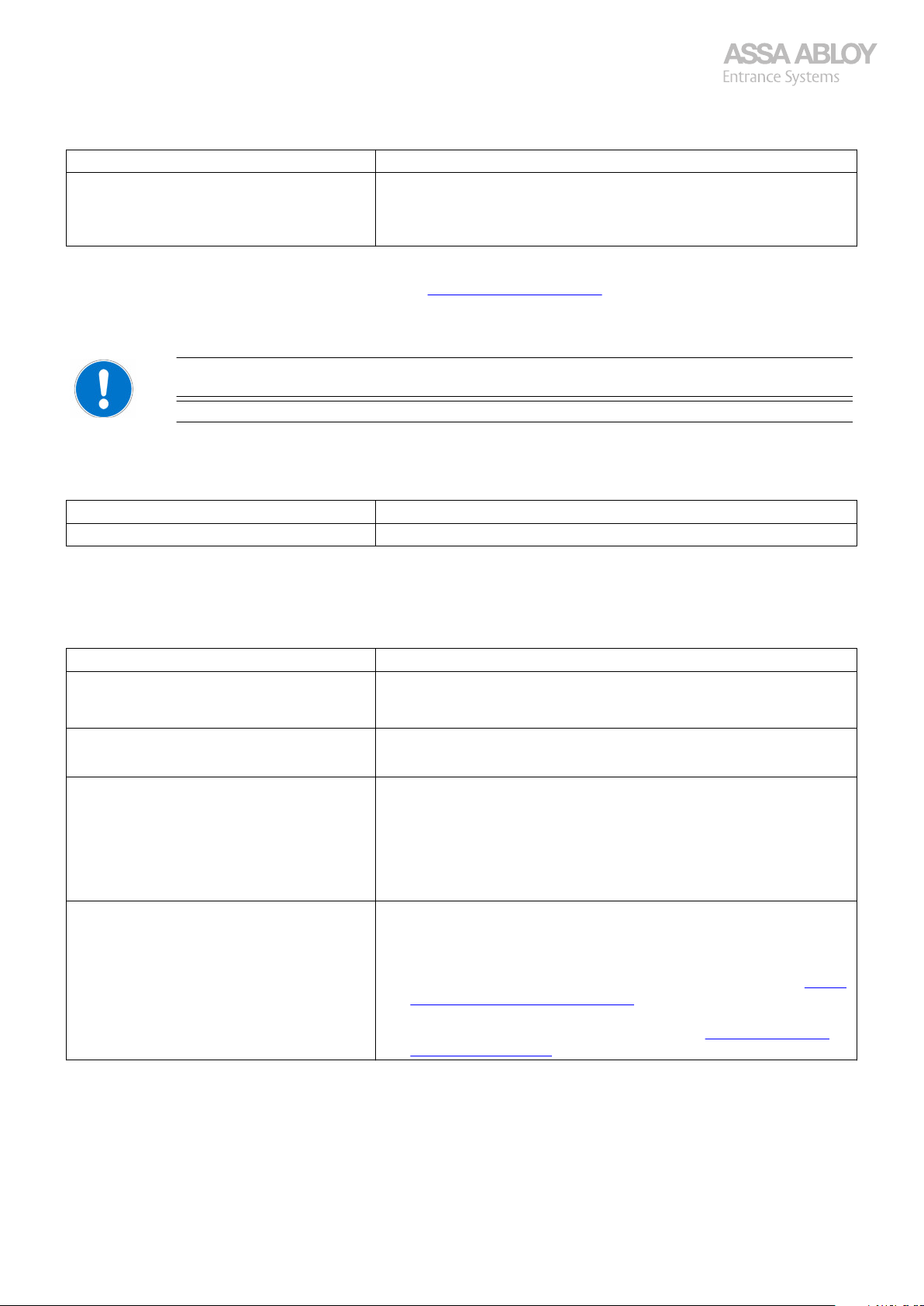
Configuration manual, installation and service
920-950 Docking
Cause Solution
20 kN loading light is lit. The lip must be retracted completely and loading process started all
Operate the leveler for a while and check all functions.
For information on error codes for the leveler, see section 4.13. Indication of errors (F) on page 80.
·
over.
Check solenoid valve V1 and its cable connection.
·
Replace valve control unit.
·
4.12
4.12.1
Dock shelter SIB starts only for a short time.
Cause Solution
Parameter settings are not set correctly. Check parameter setting: [S02] U01 = SIB.
Operate the shelter for a while and check all functions.
4.12.2
Dock shelter does not start.
Cause Solution
Summer/winter parameter is not set properly. Check the summer/winter function.
If photocell S16 for shelter interlock is connected to X19:1 – 2 – 3 on door board.
Troubleshooting steps Shelter
Follow each step in the table. If the problem on the row is not applicable, continue with the next row. The
whole table must be checked from top to bottom.
Start over from the top of the trouble shooting if something has been replaced.
Dock shelter starts only for a short time
·
Dock shelter does not start
·
Press close/auto button for 5 seconds with closed door.
·
S00 = winter, S01 = summer, change setting by open button.
Make sure there is no 24 VDC between X19:2 – X19:3 on door board.
·
SIB shelter does not start. Make sure the fuse for the main electrical supply is not blown and/or
SIR shelter does not start. Make sure the fuse for the main electrical supply is not blown and/or
Operate the shelter for a while and check all functions.
4.12.3
Dock shelter SIR does not switch off.
Dock shelter SIR does not switch off, or switch off and on again
·
230 V supply voltage at terminal X04 on basic board.
Check the wire between X04:L3 on basic board and X22:4 on door
·
board.
230 VAC between X22:3 on door board – Ground? If not replace the
·
Door board.
Check the cable to the fan, the thermal fuse of the fan and the fan.
·
·
230V supply voltage to SIR at terminal X04 on basic board.
Check 13 VAC – 24 VAC between X22:1 on door board - ground and
·
between X22:2 on door board – ground. If not check emergency stop
and its circuit, if OK troubleshoot the SIR Operator, see section 4.12.4.
Dock shelter SIR does not switch on on page 80.
Check 28 VDC – 34 VDC between X22:3 on door board – Ground. If
·
not troubleshoot the SIR Operator, see section 4.12.4. Dock shelter
SIR does not switch on on page 80.
950 Docking 79
Page 80
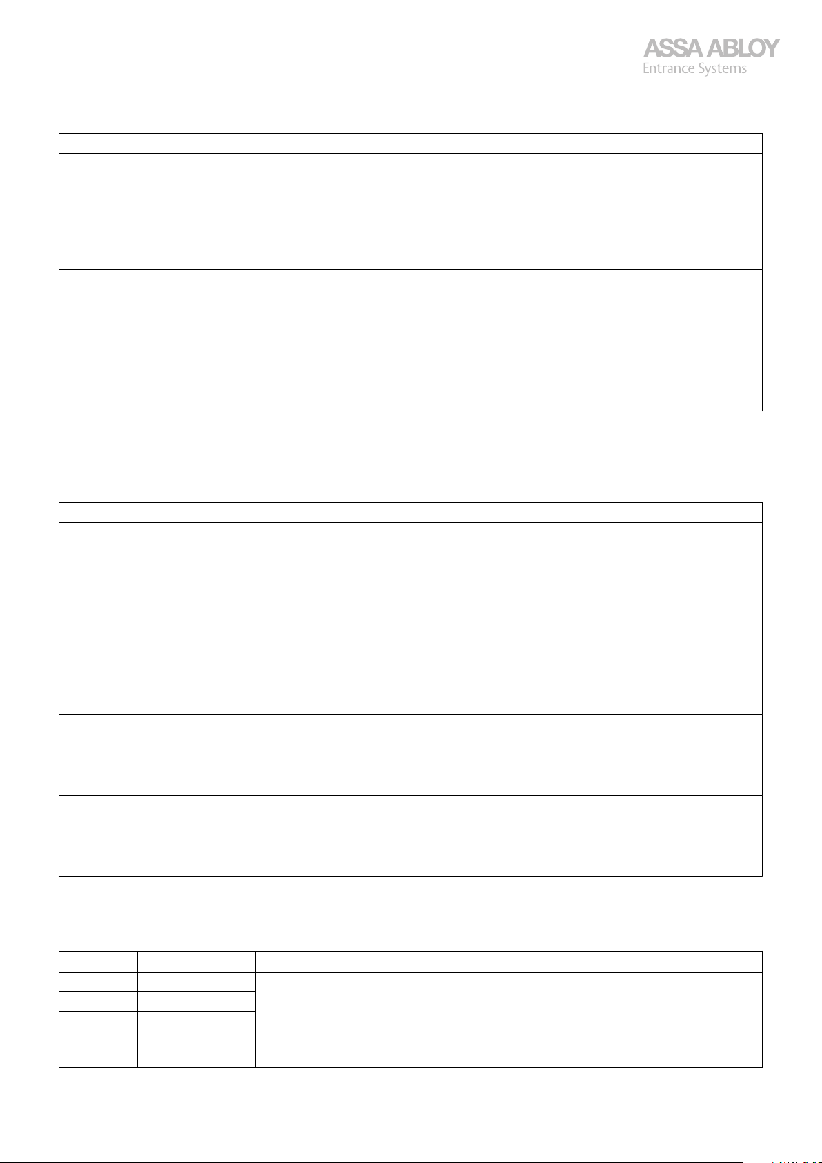
Configuration manual, installation and service
920-950 Docking
Cause Solution
SIR Top limit switch is not set correctly. Check top limit switch connection of the SIR X21:1 – 2 on the Door
No 20 VDC between X21:2-3 when SIR is on. Check 24 VDC between X21:1 – 3, if not replace the Door board.
The limit switch cables on terminal X21:1-2 are
switched.
Operate the shelter for a while and check all functions.
·
board. There shall be 0 VDC between X21:2 - 3 on door board when
SIR is in top position and about 20 VDC when SIR is on.
·
If 24 VDC between X21:1 – 3, check SIR control cable and its connec-
·
tion in SIR operator X1:4 and X1:5, see section 4.12.4. Dock shelter SIR
does not switch on on page 80.
Set the multimeter to DC.
·
Put the - on X21:3.
·
Measure then with the + on X21:2. When the upper limit switch is not
·
activated it shall be 0 V, if it is activated + 24 V DC.
If the cables are switched, +24 V DC always will always be active.
·
NOTE!
May be correct cable numbers in the 950D according to the wiring diagram, the switch might be up in the operator. If so, switch the cables
5 and 6 in the 950D.
4.12.4
Dock shelter SIR does not switch on
Cause Solution
No response when the open button is pushed,
but display in control unit is flashing start of
shelter.
The fan does not start after pushing the open
button.
The roller shelter does not wind-up after Close/
Auto button is pressed and door is closed.
The roller shelter does not wind-up the whole
way up after reaching the lower limit switch.
Dock shelter SIR does not switch on
Check the mains connection to ensure that there is power. 230 VAC at
·
connection X4:1-2 on SIR circuit board.
Check the fuse F2 on SIR circuit board.
·
If not OK check the brake and replace brake and fuse if not OK.
·
Check the fuse F1 on SIR circuit board.
·
If not OK. Replace the fuse and check cables to the SIR and limit
·
switches on SIR.
Replace the SIR circuit board.
·
Do you hear a clicking sound from the brake approximately 3 seconds
·
after pressing the start button?
If 120 VDC between X3:1-2 on SIR circuit board, replace the brake.
·
Replace the SIR circuit board.
·
Check the limit switches and adjust if necessarily.
·
Check the balancing of the roller curtain and adjust if necessarily.
·
Adjust the trimming potentiometer on SIR circuit board (R36) clock-
·
wise a bit at a time to increase the force/speed.
Check the motor of SIR. If it is not OK replace the SIR.
·
Check adjustment of the limit position switches and the balancing
·
counterweight. If necessarily adjust.
Check if the runtime has expired. If necessarily adjust trimming poten-
·
tiometer on SIR circuit board (R36) clockwise to increase the force/
speed until the curtain wind-up all the way.
Operate the shelter for a while and check all functions.
4.13
Code Fault Explanation Resolution SW
F01 Over current L1. Motor protection circuit has been trigF02 Over current L2.
F03 Over current L3.
950 Docking 80
Indication of errors (F)
gered due to too high current from
hydraulic motor.
The motor is halted for 30 sec-
·
onds. When 30 seconds has
timed out, the motor can be run
again, and the error message
goes off by pushing the LIFT-button.
All
Page 81
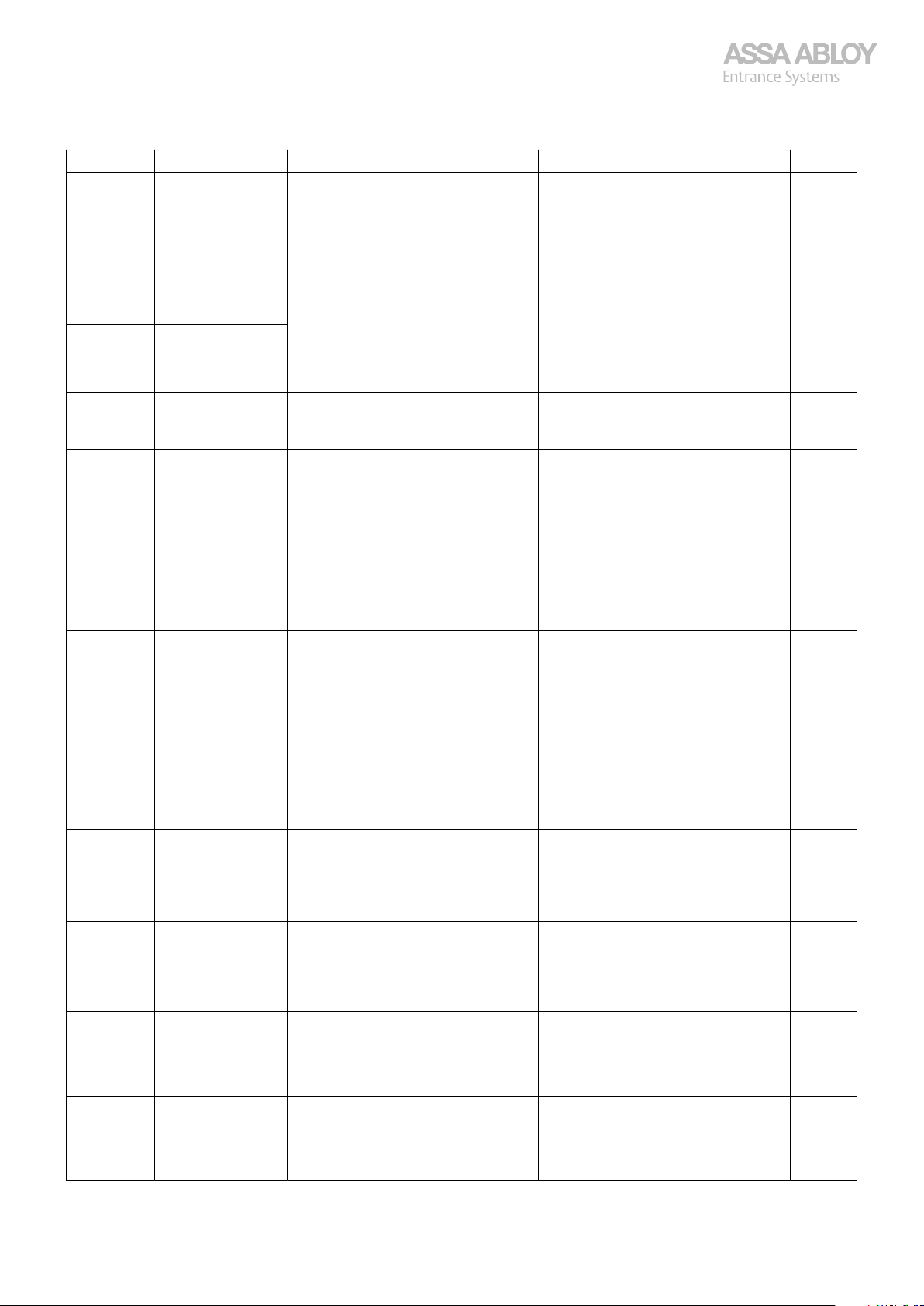
Configuration manual, installation and service
920-950 Docking
Code Fault Explanation Resolution SW
F04 Phase sequence. Phase failure or wrong phase se-
quence.
Possibly potential difference between
Neutral and Earth.
As of SW 053, only detecting for F04
during the first 2 seconds after power
on.
F05 Fault feedback V1. Fault feedback of solenoid valve (over
F06 Fault feedback V2.
F07 Fault V1 missing. Solenoid valve is missing (open cirF08 Fault V2 missing.
F09 Fault RAM test. Error in the RAM memory on the level-
F10 Fault flash test. Error in the Flash and/or register mem-
F11 Fault push buttons. Error on the internal push button pan-
F12 Fault motor cur-
rent detection.
F13 Fault 24 V control
voltage.
current/short circuit).
cuit).
er board.
ory on the leveler board.
el.
Fault in the motor current to the hy-
draulic motor detected by the motor
protection circuit, or the running tim-
er (60 seconds) triggered.
24 VDC control voltage is below -15%
and is too low.
The leveler is halted until the
·
power supply is switched off and
the error is corrected.
Check potential differences and
·
correct, if needed.
The error is considered as a fatal
·
error and the entire system is halted until the power supply has
been switched off and error is
corrected.
The leveler is halted until the
·
power supply is switched off and
the error is corrected.
The error is considered as a fatal
·
error and the entire system is halted until the power supply has
been switched off and error is
corrected.
The error is considered as a fatal
·
error and the entire system is halted until the power supply has
been switched off and error is
corrected.
The error is considered as a fatal
·
error and the entire system is halted until the power supply has
been switched off and error is
corrected.
The error is considered as a fatal
·
error and the entire system is halted until the power supply has
been switched off and error is
corrected. Wait 30 seconds after
switch off /error correction.
The leveler is halted until the
·
power supply is switched off and
the error is corrected.
All
All
All
All
All
All
All
All
F14 Feedback signal
contactor relays.
F15 Network commu-
nication (DMS).
F16 External control
box error.
950 Docking 81
Feedback signal error from contactor
relays for the hydraulic motor.
Network address is set to 255 with
DMS/IoT connected.
Selected input with U11 goes low. See documentation for external
The error is considered as a fatal
·
error and the entire system is halted until the power supply has
been switched off and error is
corrected.
Change address from 255 in
·
menu L08.
·
control unit, check cable.
All
All
044-
Page 82
Configuration manual, installation and service
920-950 Docking
Code Fault Explanation Resolution SW
888 Program damaged. Software overwritten. Replace display board. All
·
AAA Program damaged. Software overwritten. Replace leveler board. All
tSt Only test program
available.
PCB not flashed in Production. Replace or re-flash the leveler
·
·
board.
All
950 Docking 82
Page 83

Configuration manual, installation and service
920-950 Docking
83
Page 84
The ASSA ABLOY Group is the global leader in access solutions.
Every day, we help billions of people to experience a more open world.
ASSA ABLOY Entrance Systems provides solutions for efficient and safe flow of
goods and people. Our offering includes a wide range of automated pedestrian,
industrial and residential doors, loading dock equipment, perimeter fencing
and service.
©ASSA ABLOY | Configuration manual ASSA ABLOY.CDM9/en-ORG/P1303474H 2024-01 Technical data subject to change without notice
 Loading...