

Version 1.0
Published September 2015
Copyright©2015 ASRock INC. All rights reser ved.
Copyright Notice:
No part of this documentation may be reproduced, transcribed, transmitted, or
translated in any language, in any form or by any means, except duplication of
documentation by the purchaser for backup purpose, without written consent of
ASRock Inc.
Products and corporate names appearing in this documentation may or may not
be registered trademarks or copyrights of their respective companies, and are used
only for identication or explanation and to the owners’ benet, without intent to
infringe.
Disclaimer:
Specications and information contained in this documentation are furnished for
informational use only and subject to change without notice, and should not be
constructed as a commitment by ASRock. ASRock assumes no responsibility for
any errors or omissions that may appear in this documentation.
With respect to the contents of this documentation, ASRock does not provide
warranty of any kind, either expressed or implied, including but not limited to
the implied warranties or conditions of merchantability or tness for a particular
purpose.
In no event shall ASRock, its directors, ocers, employees, or agents be liable for
any indirect, special, incidental, or consequential damages (including damages for
loss of prots, loss of business, loss of data, interruption of business and the like),
even if ASRock has been advised of the possibility of such damages arising from any
defect or error in the documentation or product.
is device complies with Part 15 of the FCC Rules. Operation is subject to the following
two conditions:
(1) this device may not cause harmful interference, and
(2) this device must accept any interference received, including interference that
may cause undesired operation.
CALIFORNIA, USA ONLY
e Lithium battery adopted on this motherboard contains Perchlorate, a toxic substance
controlled in Perchlorate Best Management Practices (BMP) regulations passed by the
California Legislature. When you discard the Lithium battery in California, USA, please
follow the related regulations in advance.
“Perchlorate Material-special handling may apply, see ww w.dtsc.ca.gov/hazardouswaste/
perchlorate”
ASRock Website: http://www.asrock.com
e terms HDMI™ and HDMI High-Denition Multimedia Interface, and the HDMI
logo are trademarks or registered trademarks of HDMI Licensing LLC in the United
States and other countries.
Manufactured under license under U.S. Patent Nos: 5,956,674; 5,974,380; 6,487,535;
7,003,467 & other U.S. and worldwide patents issued & pending. DTS, the Symbol, &
DTS and the Symbol together is a registered trademark & DTS Connect, DTS Interactive,
DTS Neo:PC are trademarks of DTS, Inc. Product includes soware.
© DTS, Inc., All Rights Reserved.

Contents
Chapter 1 Introduction 1
1.1 Package Contents 1
1.2 Specications 2
1.3 Motherboard Layout 6
1.4 I/O Panel 8
Chapter 2 Installation 10
2.1 Installing the CPU 11
2.2 Installing the CPU Fan and Heatsink 14
2.3 Installing Memory Modules (DIMM) 15
2.4 Expansion Slots (PCI Express Slots) 17
2.5 Jumpers Setup 18
2.6 Onboard Headers and Connectors 19
2.7 SLITM and Quad SLITM Operation Guide 23
2.7.1 Installing Two SLITM-Ready Graphics Cards 23
2.7.2 Driver Installation and Setup 25
2.8 CrossFireXTM , 3-Way CrossFireXTM and Quad CrossFireXTM
Operation Guide 26
2.8.1 Installing Two CrossFireXTM-Ready Graphics Cards 26
2.8.2 Installing Three CrossFireXTM-Ready Graphics Cards 28
2.8.3 Driver Installation and Setup 29
2.9 M.2_SSD (NGFF) Module Installation Guide 30
Chapter 3 Software and Utilities Operation 33

3.1 Installing Drivers 33
3.2 A-Tuning 34
3.3 ASRock Live Update & APP Shop 38
3.3.1 UI Overview 38
3.3.2 Apps 39
3.3.3 BIOS & Drivers 42
3.3.4 Setting 43
3.4 Enabling USB Ports for Windows® 7 Installation 44
Chapter 4 UEFI SETUP UTILITY 47
4.1 Introduction 47
4.2 EZ Mode 48
4.3 Advanced Mode 49
4.3.1 UEFI Menu Bar 49
4.3.2 Navigation Keys 50
4.4 Main Screen 51
4.5 OC Tweaker Screen 52
4.6 Advanced Screen 61
4.6.1 CPU Conguration 62
4.6.2 Chipset Conguration 64
4.6.3 Storage Conguration 66
4.6.4 Super IO Conguration 67
4.6.5 ACPI Conguration 68
4.6.6 USB Conguration 70
4.6.7 Trusted Computing 71

4.7 Tools 72
4.8 Hardware Health Event Monitoring Screen 75
4.9 Security Screen 77
4.10 Boot Screen 78
4.11 Exit Screen 81

Z170M Extreme4
Chapter 1 Introduction
ank you for purchasing ASRock Z170M Extreme4 motherboard, a reliable
motherboard produced under ASRock’s consistently stringent quality control.
It delivers excellent performance with robust design conforming to ASRock’s
commitment to quality and endurance.
In this documentation, Chapter 1 and 2 contains the introduction of the
motherboard and step-by-step installation guides. Chapter 3 contains the operation
guide of the soware and utilities. Chapter 4 contains the conguration guide of
the BIOS setup.
Becau se the motherboard specications and the BIOS soware might be updated, the
content of this documentation will be subject to change without notice. In case any
modications of this documentation occur, the updated version will be available on
ASRock’s website w ithout f urther notice. If you require technical support relate d to
this motherboard, please vi sit our website for s pecic information about the model
you are using. You may nd the l atest VGA cards and CPU suppor t list on ASRock’s
website a s well. ASRock website ht tp://www.a srock.com.
1.1 Package Contents
ASRock Z170M Extreme4 Motherboard (Micro ATX Form Factor)
•
ASRock Z170M Extreme4 Quick Installation Guide
•
ASRock Z170M Extreme4 Support CD
•
2 x Serial ATA (SATA) Data Cables (Optional)
•
1 x I/O Panel Shield
•
1 x Screw for M.2 Socket
•
1 x ASRock SLI_Bridge Card
•
English
1

1.2 Specications
Platform
CPU
Chipset
Memory
•
•
•
•
•
•
•
•
•
•
•
* 3466+(OC) memory frequency can only be achieved when a
single memory module is installed (Single channel memory).
* Please refer to Memory Support List on ASRock's website for
more information. (http://www.asrock.com/)
•
•
•
Micro ATX Form Factor
Supports 6th Generation Intel® CoreTM i7/i5/i3/Pentium®/
Celeron® Processors (Socket 1151)
Digi Power design
6 Power Phase design
Supports Intel® Turbo Boost 2.0 Technology
Supports Intel® K-Series unlocked CPUs
Supports ASRock BCLK Full-range Overclocking
Intel® Z170
Dual Channel DDR4 Memory Technology
4 x DDR4 DIMM Slots
Supports DDR4 3466+(OC)*/3200(OC)/2933(OC)/2800(OC)
/2400(OC)/2133 non-ECC, un-buered memory
Max. capacity of system memory: 64GB
Supports Intel® Extreme Memory Prole (XMP) 2.0
15 Gold Contact in DIMM Slots
English
2
Expansion
Slot
Graphics
3 x PCI Express 3.0 x16 Slots (PCIE1/PCIE3/PCIE4: single
•
at x16 (PCIE1); dual at x8 (PCIE1) / x8 (PCIE3); triple at x8
(PCIE1) / x8 (PCIE3) / x4 (PCIE4))*
* Supports NVMe SSD as boot disks
* PCIE4 is from chipset PCIE x4 lane.
1 x PCI Express 3.0 x1 Slot (Flexible PCIe)
•
Supports AMD Quad CrossFireXTM and CrossFireXTM
•
Supports NVIDIA® Quad SLITM and SLI
•
Intel® HD Graphics Built-in Visuals and the VGA outputs
•
can be supported only with processors which are GPU
integrated.
TM

Supports Intel® HD Graphics Built-in Visuals : Intel® Quick
•
Sync Video with AVC, MVC (S3D) and MPEG-2 Full
HW Encode1, Intel® InTruTM 3D, Intel® Clear Video HD
Technology, Intel® InsiderTM, Intel® HD Graphics 510/530
Pixel Shader 5.0, DirectX 12
•
Max. shared memory 1792MB
•
Dual graphics output: Support DVI-D and HDMI ports by
•
independent display controllers
Supports HDMI with max. resolution up to 4K x 2K
•
(4096x2160) @ 24Hz / (3840x2160) @ 30Hz
Supports DVI-D with ma x. resolution up to 1920x1200 @
•
60Hz
Supports Auto Lip Sync, Deep Color (12bpc), xvYCC and
•
HBR (High Bit Rate Audio) with HDMI Port (Compliant
HDMI monitor is required)
Supports Accelerated Media Codecs: HEVC, VP8, VP9
•
Supports HDCP with DVI-D and HDMI Ports
•
Supports Full HD 1080p Blu-ray (BD) playback with DVI-D
•
and HDMI Ports
Z170M Extreme4
Audio
LAN
7.1 CH HD Audio with Content Protection (Realtek
•
ALC1150 Audio Codec)
Premium Blu-ray Audio support
•
Supports Surge Protection (ASRock Full Spike Protection)
•
Supports Purity SoundTM 3
•
- Nichicon Fine Gold Series Audio Caps
- 115dB SNR DAC with Dierential Amplier
- TI® NE5532 Premium Headset Amplier (Supports up to
600 Ohms headsets)
- Pure Power-In
- Direct Drive Technology
- PCB Isolate Shielding
Supports DTS Connect
•
Gigabit LAN 10/100/1000 Mb/s
•
Giga PHY Intel® I219V
•
Supports Wake-On-LAN
•
Supports Lightning/ESD Protection (ASRock Full Spike
•
Protection)
Supports Energy Ecient Ethernet 802.3az
•
English
3

Rear Panel
I/O
Storage
Supports PXE
•
1 x PS/2 Mouse/Keyboard Port
•
1 x DVI-D Port
•
1 x HDMI Port
•
1 x Optica l SPDIF Out Port
•
1 x USB 3.1 Type-A Port (10 Gb/s) (ASMedia ASM1142)
•
(Supports ESD Protection (ASRock Full Spike Protection))
1 x USB 3.1 Type-C Port (10 Gb/s) (ASMedia ASM1142)
•
(Supports ESD Protection (ASRock Full Spike Protection))
4 x USB 3.0 Ports (Intel® Z170) (Supports ESD Protection
•
(ASRock Full Spike Protection))
1 x RJ-45 LAN Port with LED (ACT/LINK LED and SPEED
•
LED)
HD Audio Jacks: Rear Speaker / Central / Bass / Line in /
•
Front Speaker / Microphone
6 x SATA3 6.0 Gb/s Connectors, support RAID (RAID 0,
•
RAID 1, RAID 5, RAID 10, Intel Rapid Storage Technology
14 and Intel Smart Response Technology), NCQ, AHCI and
Hot Plug
* If M2_1 is occupied by a SATA-type M.2 device, SATA3_0 and
SATA3_1 will be disabled.
1 x Ultra M.2 Socket, supports type 2242/2260/2280 M.2
•
SATA3 6.0 Gb/s module and M.2 PCI Express module up to
Gen3 x4 (32 Gb/s)**
** Supports NVMe SSD as boot disks
** Supports ASRock U.2 Kit
English
4
Connector
1 x COM Port Header
•
1 x TPM Header
•
1 x Chassis Intrusion and Speaker Header
•
1 x CPU Fan Connector (4-pin) (Smart Fan Speed Control)
•
2 x Chassis Fan Connectors (4-pin) (Smart Fan Speed Con-
•
trol)
1 x 24 pin ATX Power Connector
•
1 x 8 pin 12V Power Connector
•
1 x Front Panel Audio Connector
•
1 x USB 2.0 Header (Supports 2 USB 2.0 ports) (Supports
•
ESD Protection (ASRock Full Spike Protection))

BIOS
Feature
Hardware
Monitor
OS
Z170M Extreme4
1 x USB 3.0 Header (Supports 2 USB 3.0 ports) (Supports
•
ESD Protection (ASRock Full Spike Protection))
AMI UEFI Legal BIOS with multilingual GUI support
•
ACPI 5.0 Compliant wake up events
•
SMBIOS 2.7 Support
•
CPU, DRAM, PCH 1.0V, VCCIO, VCCSA Voltage Multi-
•
adjustment
CPU/Chassis temperature sensing
•
CPU/Chassis Fan Tachometer
•
CPU/Chassis Quiet Fan (Auto adjust chassis fan speed by
•
CPU temperature)
CPU/Chassis Fan multi-speed control
•
CASE OPEN detection
•
Voltage monitoring: +12V, +5V, +3.3V, CPU Vcore, DRAM,
•
VPPM, PCH 1.0V, VCCIO, VCCSA
Microso® Windows® 10 64-bit / 8.1 64-bit / 7 32-bit / 7 64-
•
bit
* To install Windows® 7 OS, a modied installation disk with
xHCI drivers packed into the ISO le is required. Please refer to
page 44 for more detailed instructions.
* For the updated Windows® 10 driver, please visit ASRock ’s
website for details: http://ww w.asrock.com
FCC, CE, WHQL
Certications
* For detailed product information, please visit our website: http://ww w.asrock.com
Please realize that the re is a certain r isk involved with overclo cking, including
adjusting the setting in the BIOS, applying Untied Overclocking Technol ogy, or using
third-party overclocking tool s. Overclocking may aect your system’s stability, or
even cause dam age to the components and devices of your system. It should be done
at your own risk and expense. We are not responsible for poss ible damage caused by
overclocking.
•
ErP/EuP Ready (ErP/EuP ready power supply is required)
•
English
5

1.3 Motherboard Layout
Intel
Z170
ATXP WR1
HDLED RESET
PLED P WRBTN
PANEL1
1
COM1
1
Z170 M Ex tr em e4
RoHS
2
CPU_FAN1
5
1
PCIE1
TPMS1
1
1
USB1_2
USB 3. 0
T: USB1
B: USB 2
PS2
Keybo ard
/Mous e
SPK_CI 1
1
PCIE2
Fro nt USB 3. 0
14
15
16
17
18
19
20
CMO S
Bat tery
DDR 4_A2 (6 4 bit, 28 8-pin m odule )
DDR 4_A1 (6 4 bit, 28 8-pin m odule )
DDR 4_B2 (6 4 bit, 28 8-pin m odule )
DDR 4_B1 (6 4 bit, 28 8-pin m odule )
4
3
ATX12V1
11
SATA3_2
SATA3_3
USB3_5 _6
12
13
SATA3_4
SATA3_5
10
CLRMOS1
1
1
HD_AUDI O1
PCIE4
M2_1
CT3CT4 CT2
Top:
RJ-4 5
USB 3. 0
T: USB3
B: USB 4
HDMI 1
CHA_FAN 1
21
DVI1
Top:
Central/Bass
Center :
REAR SPK
Top:
LINE IN
Center :
FRONT
Bottom :
Optica l
SPDIF
Bottom :
MIC IN
USB 3.1
T:US B31_ TA_1
B: USB3 1_TC_ 1
PCIE3
PCI E xpres s 3.0
7
8
6
9
SATA3_0
SATA3_1
CHA_FAN 2
English
6

No. Description
1 ATX 12V Power Connector (ATX12V1)
2 CPU Fan Connector (CPU_FAN1)
3 2 x 288-pin DDR4 DIMM Slots (DDR4_A1, DDR4_B1)
4 2 x 288-pin DDR4 DIMM Slots (DDR4_A2, DDR4_B2)
5 ATX Power Connector (ATXPWR1)
6 Chassis Fan Connector (CHA_FAN2)
7 USB 3.0 Header (USB3_5_6)
8 SATA3 Connector (SATA3_0)
9 SATA3 Connector (SATA3_1)
10 SATA3 Connector (SATA3_2)
11 SATA3 Connector (SATA3_3)
12 SATA3 Connector (SATA3_5)
13 SATA3 Connector (SATA3_4)
14 System Panel Header (PANEL1)
15 Chassis Intrusion and Speaker Header (SPK_CI1)
16 Clear CMOS Jumper (CLRMOS1)
17 USB 2.0 Header (USB1_2)
18 TPM Header (TPMS1)
19 COM Port Header (COM1)
20 Front Panel Audio Header (HD_AUDIO1)
21 Chassis Fan Connector (CHA_FAN1)
Z170M Extreme4
English
7
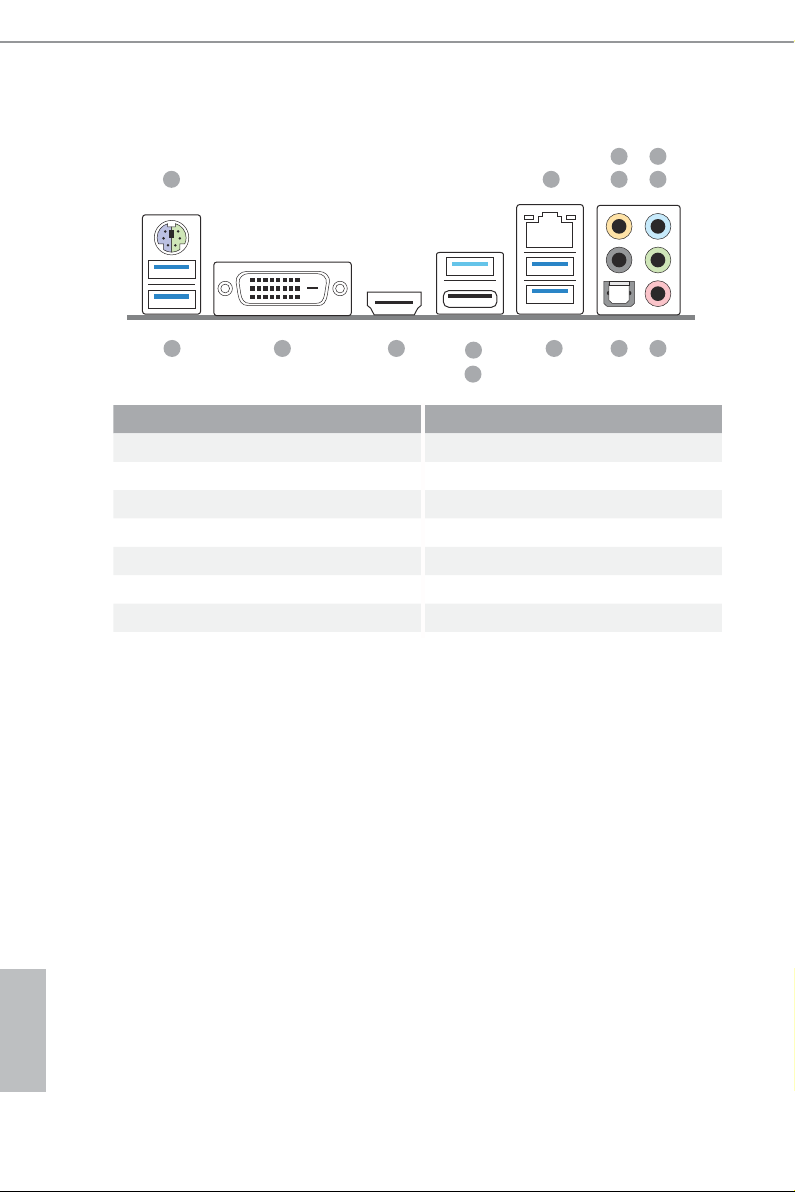
1.4 I/O Panel
1 2
5
436
14 913
No. Description No. Description
1 PS/2 Mouse/Keyboard Port 8 Optica l SPDIF Out Port
2 LAN RJ-45 Port* 9 USB 3.0 Ports (USB3_34)
3 Central / Bass (Orange) 10 USB 3.1 Type-A Port (USB31_TA_1)
4 Rear Speaker (Black) 11 USB 3.1 Type-C Port (USB31_TC_1)
5 Line In (Light Blue) 12 HDMI Port
6 Front Speaker (Lime)** 13 DVI-D Port
7 Microphone (Pink) 14 USB 3.0 Ports (USB3_12)
12
10
11
78
English
8
Z170M Extreme4
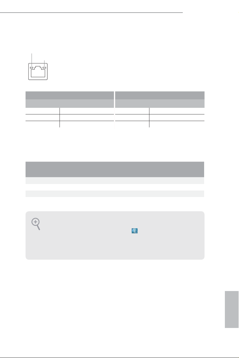
* ere are two LEDs on each LAN port. Please refer to the table below for the LAN port LED indications .
ACT/LINK L ED
SPEED LE D
LAN Por t
Activity / Link LED Speed LED
Status Description Status Description
O No Link O 10Mbps connection
Blinking Data Activity Orange 100Mbps connection
On Link Green 1Gbps connection
** If you use a 2- channel speaker, plea se connect the speake r’s plug into “Front Speaker Jack”. See the table below
for connection d etails in accordance w ith the type of speaker you use.
Audio Output
Channels
Front Speaker
(No. 6)
Rear Speaker
(No. 4)
Central / Bass
(No. 3)
2 V -- -- --
4 V V -- --
6 V V V --
8 V V V V
To enable Multi-Streaming, you need to connect a front panel audio cable to the
front panel audio header. Aer restarting your computer, you will nd the “Mixer”
tool on your system. Plea se select “Mixe r ToolBox” , click “Enable playback
multi-streaming”, and click “ok”. Choose “2CH”, “4CH”, “6CH”, or “8CH” and then
you are all owed to select “Realtek HDA Primary out put” to u se the Rear Speak er,
Central/Bas s, and Front Speaker, or select “Realtek HDA Audio 2nd output” to u se
the front panel au dio.
Line In
(No. 5)
English
9

Chapter 2 Installation
is is a Micro ATX form factor motherboard. Before you install the motherboard,
study the conguration of your chassis to ensure that the motherboard ts into it.
Pre-installation Precautions
Take note of the following precautions before you install motherboard components
or change any motherboard settings.
Make sure to unplug the power cord before installing or removing the motherboard
•
components. Failure to do so may cause physical injuries and damages to motherboard
components.
In order to avoid damage from static electricity to the motherboard’s components,
•
NEVER place your motherboard directly on a carpet. Also remember to use a grounded
wrist strap or touch a safety grounded object before you handle the components.
Hold components by the edges and do not touch the ICs.
•
Whenever you uninstall any components, place them on a grounded anti-static pad or
•
in the bag that comes with the components.
When placing screws to secure the motherboard to the chassis, please do not over-
•
tighten the screws! Doing so may damage the motherboard.
English
10
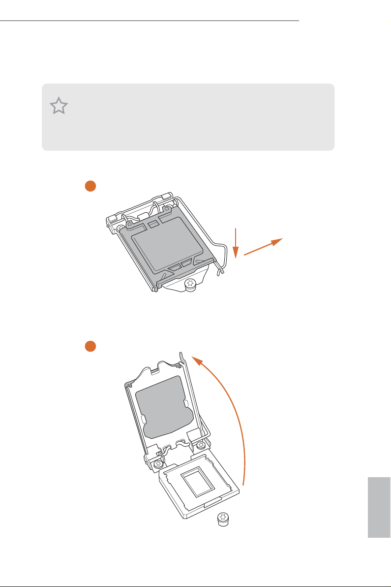
2.1 Installing the CPU
1. Before you insert the 1151-Pin CPU into th e socket, please check if the PnP cap is on
the socket, if the CPU surfa ce is unclean, or if there are any bent pins in the socket.
Do not force to insert the CPU into the socket if above situation is found. Otherwise,
the CPU will be seriously damaged .
2. Unplug all power c ables before in stalling the CPU.
1
Z170M Extreme4
A
B
2
English
11
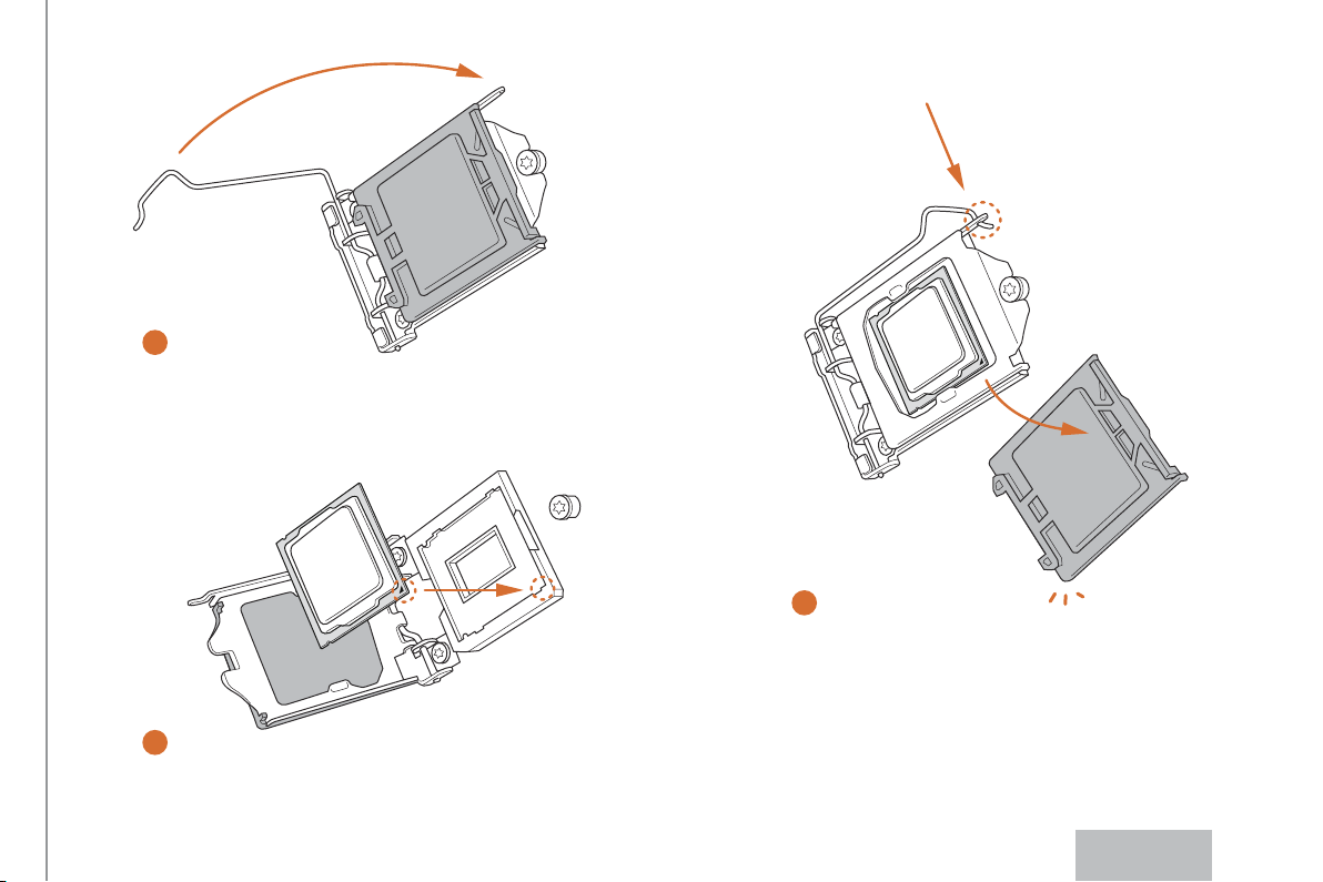
4
5
3
12
English

Please save and replace the cover if the processor i s removed. e cover must be placed
if you wish to retur n the motherboard for aer service.
Z170M Extreme4
13
English
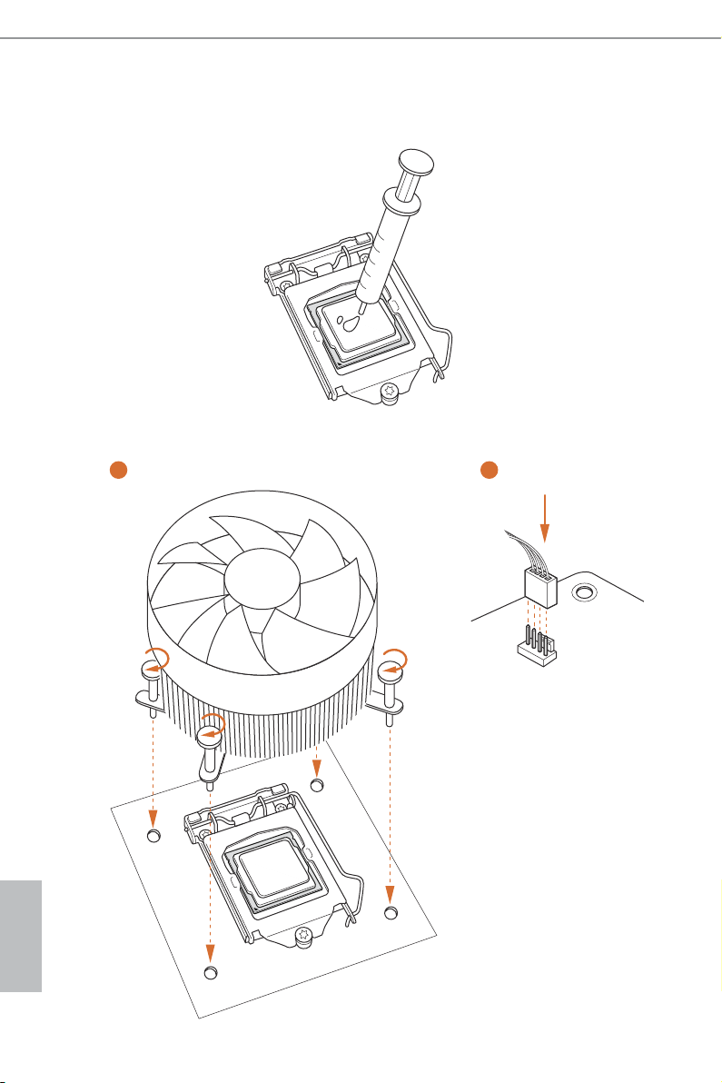
2.2 Installing the CPU Fan and Heatsink
1 2
English
14
FAN
CPU_
Z170M Extreme4
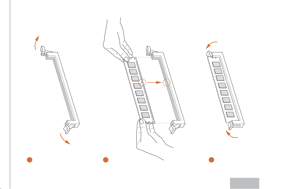
2.3 Installing Memory Modules (DIMM)
is motherboard provides four 288-pin DDR4 (Double Data Rate 4) DIMM slots,
and supports Dual Channel Memory Technology.
1. For dual channel conguration, you always need to install identica l (the same
brand, speed , size and chip-type) DDR4 DIMM pairs.
2. It is unable to activate Dual Channel Memor y Te chnology with only one or three
memor y module installed.
3. It is not allowed to install a DDR, DDR2 or DDR3 memory module into a DDR4
slot; otherwise, this motherboard and DIMM may be damaged.
Dual Channel Memory Conguration
Priority DDR4_ A1 DDR4_ A2 DDR4_B1 DDR4_B2
1 Populated Populated
2 Populated Populated
3 Populated Populated Populated Populated
e DIMM only ts in one correct orientation. It will cause permanent dam age to
the mothe rboard and the DIMM if you force the DIMM into the slot at incor rect
orientation .
15
English
1
2
3
16
English
2.4 Expansion Slots (PCI Express Slots)
ere are 4 PCI Express slots on the motherboard.
Before installing an ex pansion card, please make sure that the power supply is
switched o or the power cord is unplugged. Plea se read the documentation of the
expan sion card and mak e necessary hardware settings for the card before you start
the installation.
PCIe slots:
PCIE1 (PCIe 3.0 x16 slot) is used for PCI Express x16 lane width graphics cards.
PCIE2 (PCIe 3.0 x1 slot) is used for PCI Express x1 lane width cards.
PCIE3 (PCIe 3.0 x16 slot) is used for PCI Express x8 lane width graphics cards.
PCIE4 (PCIe 3.0 x16 slot) is used for PCI Express x4 lane width graphics cards.
PCIe Slot Congurations
PCIE1 PCIE3 PCIE4
Single Graphics Card x16 N/A N/A
Z170M Extreme4
Two Graphics Cards in
CrossFireXTM or SLITM
Mode
ree Graphics Cards in
3-Way CrossFireXTM Mode
For a better ther mal environment, ple ase connect a ch assi s fan to the motherboard’s
chassis fan connector (CHA_ FAN1 or CHA_ FAN2) when using multiple graphics
cards.
x8 x8 N/A
x8 x8 x4
English
17
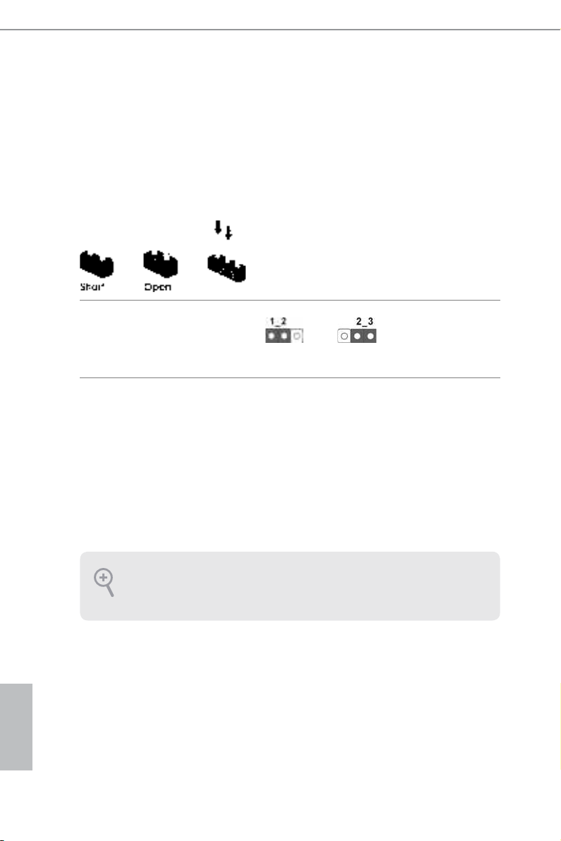
2.5 Jumpers Setup
e illustration shows how jumpers are setup. When the jumper cap is placed on
the pins, the jumper is “Short”. If no jumper cap is placed on the pins, the jumper
is “Open”. e illustration shows a 3-pin jumper whose pin1 and pin2 are “Short”
when a jumper cap is placed on these 2 pins.
Clear CMOS Jumper
(CLRMOS1)
(see p.6, No. 16)
CLRMOS1 allows you to clear the data in CMOS. To clear and reset the system
parameters to default setup, please turn o the computer and unplug the power
cord from the power supply. Aer waiting for 15 seconds, use a jumper cap to
short pin2 and pin3 on CLRMOS1 for 5 seconds. However, please do not clear the
CMOS right aer you update the BIOS. If you need to clear the CMOS when you
just nish updating the BIOS, you must boot up the system rst, and then shut it
down before you do the clear-CMOS action. Please be noted that the password,
date, time, and user default prole will be cleared only if the CMOS battery is
removed.
Clear CMOSDefault
English
18
If you clear the CMOS, the case open may be detec ted. Please adjust the BIOS option
“Clear Status” to clear the record of previou s chassis intrusion status.
2.6 Onboard Headers and Connectors
Onboard headers and connectors are NOT jumpers. Do NOT place jumper caps over
these header s and connectors. Placing jumper caps over the headers and connectors
will cause permanent damage to the motherboard.
Z170M Extreme4
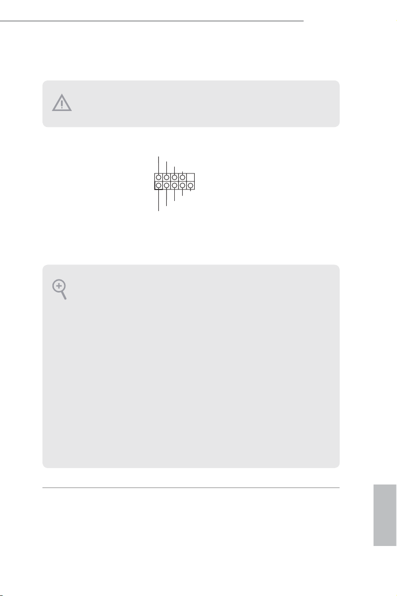
System Panel Header
(9-pin PANEL1)
(see p.6, No. 14)
PWRBTN (Power Switch):
Connec t to the power switch on the chassi s front panel. You may congure the way to
turn o your system using the power switch.
RESET (Reset Switch):
Connec t to the reset switch on the chassi s front panel. P ress the reset sw itch to restart
the computer if the compute r freezes and fails to perform a normal restart.
PLED (Syste m Power LED):
Connec t to the power status indicator on the chassis front panel. e LED i s on when
the system is ope rating. e LED keeps blinking when the system i s in S1/S3 sleep
state. e LED is o when the system is in S4 sleep state or powered o (S5).
HDLED (Ha rd Drive Activity LED):
Connec t to the hard drive ac tivity LED on the chassis front panel. e LED is on
when the hard drive i s reading or writing data.
e front panel de sign may dier by chassis. A front pane l module mainly consists
of power switch , reset switch, power LED, hard dr ive activity LED, speak er and etc.
When connecting your chassis front panel module to this head er, make sure the wire
assig nments and the pin assig nments are matched correctly.
1
PLE D+
PLE D-
HDL ED-
HDL ED+
PWR BTN#
GND
RES ET#
GND
GND
Connect the power
switch, reset switch and
system status indicator on
the chassis to this header
according to the pin
assignments below. Note
the positive and negative
pins before connecting
the cables.
19
English
Chassis Intrusion and
SPE AKER
Speaker Header
(7-pin SPK_CI1)
(see p.6, No. 15)
DUM MY
+5V
1
SIG NAL
DUM MY
GND
DUM MY
Please connect the
chassis intrusion and the
chassis speaker to this
header.
English
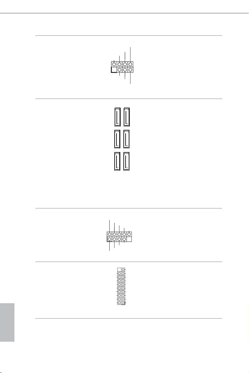
Serial ATA3 Connectors
(SATA3_0:
see p.6, No. 8)
(SATA3_1:
see p.6, No. 9)
(SATA3_2:
see p.6, No. 10)
(SATA3_3:
see p.6, No. 11)
(SATA3_4:
see p.6, No. 13)
(SATA3_5:
see p.6, No. 12)
USB 2.0 Header
(9-pin USB1_2)
(see p.6, No. 17)
USB 3.0 Header
(19-pin USB3_5_6)
(see p.6, No. 7)
SATA3_0
SATA3_2
SATA3_4
USB _PWR
1
USB _PWR
IntA _PA_SS RX-
IntA _PA_SS RX+
IntA _PA_SS TX-
IntA _PA_SS TX+
IntA _PA_D-
IntA _PA_D+
Vbus
GND
GND
ese six SATA3
connectors support SATA
data cables for internal
SATA3_1
storage devices with up to
6.0 Gb/s data transfer rate.
* If M2_1 is occupied by
SATA3_3
a SATA-type M.2 device,
SATA3_0 and SATA3_1
will be disabled.
SATA3_5
P-
P+
GND
DUM MY
GND
P+
P-
VbusVbus
IntA _PB_S SRX-
IntA _PB_S SRX+
GND
IntA _PB_S STX-
IntA _PB_S STX+
GND
IntA _PB_D -
IntA _PB_D +
Dumm y
1
ere is one header on
this motherboard. is
USB 2.0 header can
support two ports.
Besides four USB 3.0
ports on the I/O panel,
there is one header on this
motherboard. is USB
3.0 header can support
two ports.
20
Z170M Extreme4
FAN_S PEED_ CONTR OL
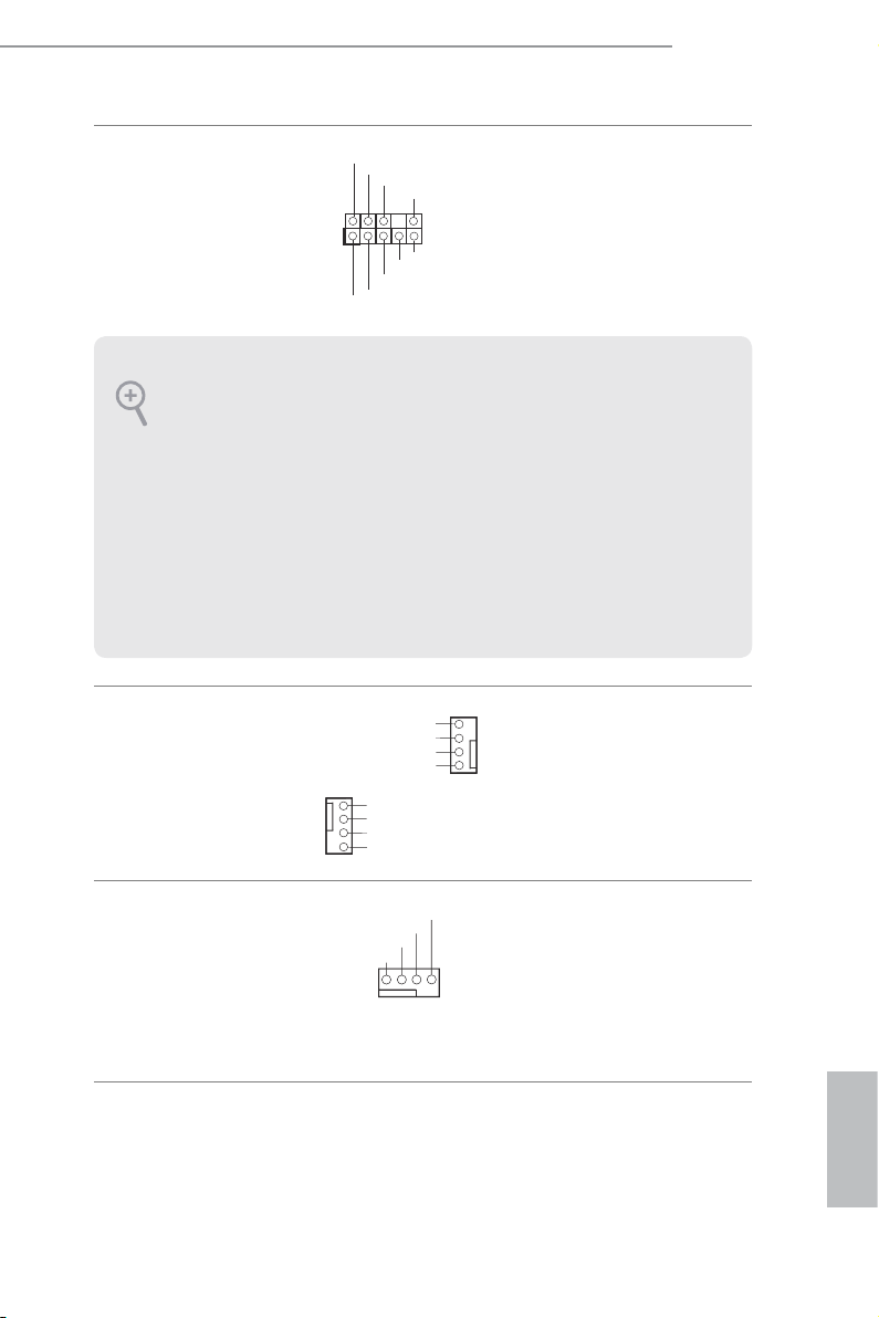
Front Panel Audio Header
(9-pin HD_AUDIO1)
(see p.6, No. 20)
1. High Denition Audio supports Jack Sensing, but the panel wire on the chassis
must support HDA to function correctly. Please follow the instructions in our
manual and chassis manual to install your system.
2. If you use an AC’97 audio panel, please install it to the front panel audio heade r by
the steps below:
A. Connect Mic_IN (MIC) to MIC2_ L.
B. Conne ct Audio_R (RIN) to OUT2_R and Audio_ L (LIN) to OUT2_ L.
C. Connect Ground (GND) to Ground (GND).
D. MIC_ RET and OUT_RET are for the HD audio panel only. You don’t need to
connec t them for the AC’97 audio panel.
E. To activate the front mic, go to the “FrontMic” Tab in the Realtek Control panel
and adju st “Recording Volume”.
Chassis Fan Connectors
(4-pin CHA_FAN1)
(see p.6, No. 21)
(4-pin CHA_FAN2)
(see p.6, No. 6)
GND
PRE SENCE #
MIC _RET
1
FAN _SP EED _CO NT ROL
OUT 2_L
J_S ENSE
OUT 2_R
MIC 2_R
MIC 2_L
CHA _FA N_S PEE D
FAN _VO LTA GE
GND
GND
FAN_VOLTAGE
CHA _FA N_S PEE D
FAN _SP EED _CO NT ROL
OUT _RET
is header is for
connecting audio devices
to the front audio panel.
Please connect fan cables
to the fan connectors and
match the black wire to
the ground pin.
CPU Fan Connector
(4-pin CPU_FAN1)
(see p.6, No. 2)
CPU_ FAN_SP EED
FAN_ VOLTA GE
GND
1 2 3 4
is motherboard pro-
vides a 4-Pin CPU fan
(Quiet Fan) connector.
If you plan to connect a
3-Pin CPU fan, please
connect it to Pin 1-3.
English
21
 Loading...