

ASRock P45R200, P45R2000-WIFI Installation Guide

Copyright Notice:Copyright Notice:
Copyright Notice:
Copyright Notice:Copyright Notice:
No part of this installation guide may be reproduced, transcribed, transmitted, or translated in any language, in any form or by any means, except duplication of documentation by the purchaser for backup purpose, without written consent of ASRock Inc.
Products and corporate names appearing in this guide may or may not be registered
trademarks or copyrights of their respective companies, and are used only for identification or explanation and to the owners’ benefit, without intent to infringe.
Disclaimer:Disclaimer:
Disclaimer:
Disclaimer:Disclaimer:
Specifications and information contained in this guide are furnished for informational
use only and subject to change without notice, and should not be constructed as a
commitment by ASRock. ASRock assumes no responsibility for any errors or omissions
that may appear in this guide.
With respect to the contents of this guide, ASRock does not provide warranty of any kind,
either expressed or implied, including but not limited to the implied warranties or
conditions of merchantability or fitness for a particular purpose. In no event shall
ASRock, its directors, officers, employees, or agents be liable for any indirect, special,
incidental, or consequential damages (including damages for loss of profits, loss of
business, loss of data, interruption of business and the like), even if ASRock has been
advised of the possibility of such damages arising from any defect or error in the guide
or product.
This device complies with Part 15 of the FCC Rules. Operation is subject to the
following two conditions:
(1) this device may not cause harmful interference, and
(2) this device must accept any interference received, including interference that
may cause undesired operation.
CALIFORNIA, USA ONLY
The Lithium battery adopted on this motherboard contains Perchlorate, a toxic
substance controlled in Perchlorate Best Management Practices (BMP) regulations
passed by the California Legislature. When you discard the Lithium battery in
California, USA, please follow the related regulations in advance.
“Perchlorate Material-special handling may apply, see
www.dtsc.ca.gov/hazardouswaste/perchlorate”
ASRock Website: http://www.asrock.com
Published May 2008
Copyright©2008 ASRock INC. All rights reserved.
ASRock P45R2000-WiFi / P45R2000 / P45TurboTwins2000 Motherboard
EnglishEnglish
EnglishEnglish
English
11
1
11

Motherboard LMotherboard L
Motherboard L
Motherboard LMotherboard L
ayoutayout
ayout
ayoutayout
English
EnglishEnglish
EnglishEnglish
22
2
22
(P45R2000-(P45R2000-
(P45R2000-
(P45R2000-(P45R2000-
1 CPU Fan Connector (CPU_FAN1) 22 USB 2.0 Header (USB8_9, Blue)
2 eSATAII Connector (eSATAII_BOTTOM (Port 5)) 23 System Panel Header (PANEL1)
3 eSATAII Connector (eSATAII_TOP (Port 4)) 24 USB 2.0 Header (USB6_7, Blue)
4 775-Pin CPU Socket 25 Chassis Fan Connector (CHA_FAN1)
5 PS2_USB_PWR1 Jumper 26 SPI BIOS Chip
6 2 x 240-pin DDR2 DIMM Slots 27 Front Panel IEEE 1394 Header
(Dual Channel A: DDRII_1, DDRII_2; Yellow) (FRONT_1394)
7 2 x 240- p in DD R3 D IM M S l ot s 28 DeskExpress Hot Plug Detection Header
(Dual Channel B: DDR3_A1, DDR3_B1; Green) (IR1)
8 2 x 240-pin DD R3 DI MM S lot s 29 Floppy Connector (FLOPPY1)
(Dual Channel C: DDR3_A2, DDR3_B2; Pink) 30 COM Port Header (COM1)
9 IDE1 Connector (IDE1, Blue) 31 WiFi/E Header (WIFI/E)
10 FSB3 Jumper 32 Front Panel Audio Header (HD_AUDIO1)
11 FSB2 Jumper 33 HDMI_SPDIF Header (HDMI_SPDIF1)
12 FSB1 Jumper 34 Internal Audio Connector: CD1 (Black)
13 South Bridge Controller 35 PCI Slots (PCI1 - 3)
14 Clear CMOS Jumper (CLRCMOS1) 36 PCI Express 2.0 x16 Slot (PCIE4, Blue)
15 Chassis Speaker Header (SPEAKER 1) 37 SLI/XFire Switch Card Retention Slot
16 SATAII Connector (SATAII_6 (Port5), Orange) 38 PCI Express x1 Slot (PCIE3)
17 SATAII Connector (SATAII_5 (Port4), Orange) 39 PCI Express 2.0 x16 Slot (PCIE2, Green)
18 SATAII Connector (SATAII_3 (Port2), Red) 40 PCI Express x1 Slot (PCIE1/DE)
19 SATAII Connector (SATAII_4 (Port3), Red) 41 ATX Power Connector (ATXPWR1)
20 SATAII Connector (SATAII_1 (Port0), Red) 42 ATX 12V Connector (ATX12V1)
21 SATAII Connector (SATAII_2 (Port1), Red)
ASRock P45R2000-WiFi / P45R2000 / P45TurboTwins2000 Motherboard
WiFWiF
i / P45R2000)i / P45R2000)
WiF
i / P45R2000)
WiFWiF
i / P45R2000)i / P45R2000)

Motherboard LMotherboard L
Motherboard L
Motherboard LMotherboard L
1 CPU Fan Connector (CPU_FAN1) 21 SATAII Connector (SATAII_2 (Port1), Red)
2 eSATAII Connector (eSATAII_BOTTOM (Port 5)) 22 USB 2.0 Header (USB8_9, Blue)
3 eSATAII Connector (eSATAII_TOP (Port 4)) 23 System Panel Header (PANEL1)
4 775-Pin CPU Socket 24 USB 2.0 Header (USB6_7, Blue)
5 PS2_USB_PWR1 Jumper 25 Chassis Fan Connector (CHA_FAN1)
6 2 x 240-pin DDR2 DIMM Slots 26 SPI BIOS Chip
(Dual Channel A: DDRII_1, DDRII_2; Yellow) 27 DeskExpress Hot Plug Detection Header
7 2 x 240-p in DDR 3 D IM M S lo ts (IR1)
(Dual Channel B: DDR3_A1, DDR3_B1; Green) 28 Floppy Connector (FLOPPY1)
8 2 x 240-pin DDR3 DIMM Slots 29 COM Port Header (COM1)
(Dual Channel C: DDR3_A2, DDR3_B2; Pink) 30 WiFi/E Header (WIFI/E)
9 IDE1 Connector (IDE1, Blue) 31 Front Panel Audio Header (HD_AUDIO1)
10 FSB3 Jumper 32 HDMI_SPDIF Header (HDMI_SPDIF1)
11 FSB2 Jumper 33 Internal Audio Connector: CD1 (Black)
12 FSB1 Jumper 34 PCI Slots (PCI1 - 3)
13 South Bridge Controller 35 PCI Express 2.0 x16 Slot (PCIE4, Blue)
14 Clear CMOS Jumper (CLRCMOS1) 36 SLI/XFire Switch Card Retention Slot
15 Chassis Speaker Header (SPEAKER 1) 37 PCI Express x1 Slot (PCIE3)
16 SATAII Connector (SATAII_6 (Port5), Orange) 38 PCI Express 2.0 x16 Slot (PCIE2, Green)
17 SATAII Connector (SATAII_5 (Port4), Orange) 39 PCI Express x1 Slot (PCIE1/DE)
18 SATAII Connector (SATAII_3 (Port2), Red) 40 ATX Power Connector (ATXPWR1)
19 SATAII Connector (SATAII_4 (Port3), Red) 41 ATX 12V Connector (ATX12V1)
20 SATAII Connector (SATAII_1 (Port0), Red)
ayout (P45Tayout (P45T
ayout (P45T
ayout (P45Tayout (P45T
urboTurboT
urboT
urboTurboT
wins2000)wins2000)
wins2000)
wins2000)wins2000)
EnglishEnglish
EnglishEnglish
English
ASRock P45R2000-WiFi / P45R2000 / P45TurboTwins2000 Motherboard
33
3
33

ASRASR
ock DualLock DualL
ASR
ock DualL
ASRASR
ock DualLock DualL
AN_SPDIF I/OAN_SPDIF I/O
AN_SPDIF I/O
AN_SPDIF I/OAN_SPDIF I/O
English
EnglishEnglish
EnglishEnglish
(P45R2000-(P45R2000-
(P45R2000-
(P45R2000-(P45R2000-
1 PS/2 Mouse Port (Green) ** 10 Front Speaker (Lime)
2 Coaxial SPDIF Out Port 11 Microphone (Pink)
3 IEEE 1394 Port 12 USB 2.0 Ports (USB45)
* 4 LAN RJ-45 Port 13 USB 2.0 Ports (USB23)
* 5 LAN RJ-45 Port 14 USB 2.0 Ports (USB01)
6 Side Speaker (Gray) 15 eSATAII Port (eSATAII_TOP)
7 Rear Speaker (Black) 16 eSATAII Port (eSAT AII_BOTTOM)
8 Central / Bass (Orange) 17 Optical SPDIF Out Port
9 Line In (Light Blue) 18 PS/2 Keyboard Port (Purple)
* There are two LED next to the LAN port. Please refer to the table below for the LAN port LED
indications.
SPEED LED Activity/Link LED
Status Description Status Description
Off 10Mbps connection Off No link
Orange 100Mbps connection Orange Linked
Green 1Gbps connection Blinking Data Activity
** If you use 2-channel speaker, please connect the speaker’s plug into “Front Speaker Jack”.
See the table below for connection details in accordance with the type of speaker you use.
Audio Output Channels Front Speaker Rear Sp eaker Central / Bass Side Speaker
WiFWiF
i / P45R2000)i / P45R2000)
WiF
i / P45R2000)
WiFWiF
i / P45R2000)i / P45R2000)
LAN Port LED Indications
TABLE f or Audio Output Connection
(No. 10) (No. 7) (No. 8) (No. 6)
2 V -- -- -4VV---6 VVV-8 VVVV
SPEED
LED
ACT/LINK
LED
LAN Port
To enable Multi-Streaming function, you need to connect a front panel audio cable to the front
panel audio header. After restarting your computer, you will find “Mixer” tool on your system.
Please select “Mixer ToolBox” , click “Enable playback multi-streaming”, and click
“ok”. Choose “2CH”, “4CH”, “6CH”, or “8CH” and then you are allowed to select “Realtek HDA
Primary output” to use Rear Speaker, Central/Bass, and Front Speaker, or select “Realtek
HDA Audio 2nd output” to use front panel audio.
44
4
44
ASRock P45R2000-WiFi / P45R2000 / P45TurboTwins2000 Motherboard

ACT/LINK
LED
LAN Port
ASRASR
ock SPDIF I/O Plus (P45Tock SPDIF I/O Plus (P45T
ASR
ock SPDIF I/O Plus (P45T
ASRASR
ock SPDIF I/O Plus (P45Tock SPDIF I/O Plus (P45T
1 PS/2 Mouse Port (Green) 9 Microphone (Pink)
2 Coaxial SPDIF Out Port 10 USB 2.0 Ports (USB45)
* 3 LAN RJ-45 Port 11 USB 2.0 Ports (USB23)
4 Side Speaker (Gray) 12 USB 2.0 Ports (USB01)
5 Rear Speaker (Black) 13 eSATAII Port (eSATAII_TOP)
6 Central / Bass (Orange) 14 eSATAII Port (eSATAII_BOTTOM)
7 Line In (Light Blue) 15 Optical SPDIF Out Port
** 8 Front Speaker (Lime) 16 PS/2 Keyboard Port (Purple)
* There are two LED next to the LAN port. Please refer to the table below for the LAN port LED
indications.
SPEED LED Activity/Link LED
Status Description Status Description
Off 10Mbps connection Off No link
Orange 100Mbps connection Orange Linked
Green 1Gbps connection Blinking Data Activity
** If you use 2-channel speaker, please connect the speaker’s plug into “Front Speaker Jack”.
See the table below for connection details in accordance with the type of speaker you use.
Audio Output Channels Front Speaker Rear Sp eaker Central / Bass Side Speaker
LAN Port LED Indications
TABLE f or Audio Output Connection
(No. 8) (No. 5) (No. 6) (No. 4)
2 V -- -- -4VV---6 VVV-8 VVVV
urboTurboT
urboT
urboTurboT
wins2000)wins2000)
wins2000)
wins2000)wins2000)
SPEED
LED
ACT/LINK
LED
LAN Port
To enable Multi-Streaming function, you need to connect a front panel audio cable to the front
panel audio header. After restarting your computer, you will find “Mixer” tool on your system.
Please select “Mixer ToolBox” , click “Enable playback multi-streaming”, and click
“ok”. Choose “2CH”, “4CH”, “6CH”, or “8CH” and then you are allowed to select “Realtek HDA
Primary output” to use Rear Speaker, Central/Bass, and Front Speaker, or select “Realtek
HDA Audio 2nd output” to use front panel audio.
ASRock P45R2000-WiFi / P45R2000 / P45TurboTwins2000 Motherboard
EnglishEnglish
EnglishEnglish
English
55
5
55

English
EnglishEnglish
EnglishEnglish
ASRock WiFi-802.11g Module SpecificationsASRock WiFi-802.11g Module Specifications
ASRock WiFi-802.11g Module Specifications
ASRock WiFi-802.11g Module SpecificationsASRock WiFi-802.11g Module Specifications
(F(F
or P45R2000-or P45R2000-
(F
or P45R2000-
(F(F
or P45R2000-or P45R2000-
ASRock WiFi-802.1 1g module is a n e asy-to-use wireless local area network (WLAN)
ada pter to support WiFi+AP function. With ASRock WiFi-802.11g module, you can
easily cre ate a wireless environment a nd en joy the convenience of wireless network
connectivity . Therefore, from anywhere within the signal range, you will be able to play
LAN games, connect to the internet, access a nd share printers, and make Internet
phone calls easily.
Standard - IEEE 802.11g
Data Rate - 6, 9, 12, 18, 24, 36, 48, 54Mbps
Security - Access Point mode (AP mode): WEP, WPA
Network - Access Point mode (AP mode)
Architecture Type s - Station mode: Infrastructure mode and Ad-Hoc mode
Frequency Band - 2.4~2.5GHz
Operating Range - Indoor: 80ft (30m)
Number of - up to 16 stations
Connected Devices
(AP Mode)
Antenna - ASRock WiFi-802.1 1g omni-directional antenna
LED - Green data tra nsmission (AIR) LED
Support OS - Windows® XP / XP 64-bit / VistaTM / VistaTM 64-bit
Compatibility - Full compatible with IEEE 802.1 1g standard products
Software Support - ASRock WiFi-802.11g Wizard
WiFWiF
i Only)i Only)
WiF
i Only)
WiFWiF
i Only)i Only)
Outdoor: 200ft (60m)
* The range varies in dif ferent environments
If you want to start to use ASRock WiFi-802.11g module on this motherboard, please
carefully read “ASRock WiFi-802.1 1g Module Operation Guide” in the package f or
the detailed introduction and operation procedures. You can also rea d the document in
the following path of ASRock motherboard support CD:
..\ ASRock WiFi-802.1 1g \ V ista64_V ista _XP64_XP
66
6
66
ASRock P45R2000-WiFi / P45R2000 / P45TurboTwins2000 Motherboard

1. Introduction1. Introduction
1. Introduction
1. Introduction1. Introduction
Thank you for purcha sing ASRock P45R2000-WiFi / P45R2000 / P45TurboTwins2000
motherboard, a reliable motherboard produced under ASRock’s con sistently stringent
quality control. It delivers excellent performance with robust design conf orming to ASRock’s
commitment to quality and endurance.
This Quick Installation Guide contains introduction of the motherboard and step-bystep installation guide. More detailed information of the motherboard can be found in
the user manual presented in the Support CD.
Because the motherboard specifications and the BIOS software might be
updated, the content of this manual will be subject to change without
notice. In case any modifications of this manual occur, the updated
version will be available on ASRock website without further notice. You
may find the latest VGA cards and CPU support lists on ASRock website
as well. ASRock website http://www.asrock.com
If you require technical support related to this motherboard, please visit
our website for specific information about the model you are using.
www.asrock.com/support/index.asp
1.1 P1.1 P
1.1 P
1.1 P1.1 P
ASRock P45R2000-WiFi / P45R2000 / P45TurboTwins2000 Motherboard
ASRock P45R2000-WiFi / P45R2000 / P45TurboT wins2000 Quick Installation Guide
ASRock P45R2000-WiFi / P45R2000 / P45TurboTwins2000 Support CD
ASRock WiFi-802.11g Module Operation Guide (For P45R2000-WiFi Only)
Motherboard Accessories
WiFi Accessories (For P45R2000-WiFi Only)
ackack
age Contentsage Contents
ack
age Contents
ackack
age Contentsage Contents
(ATX Form Factor: 12.0-in x 9.6-in, 30.5 cm x 24.4 cm)
One ASRock SLI/XFire Switch Card
One 80-conductor Ultra A TA 66/100/133 IDE Ribbon Cable
One Ribbon Cable for a 3.5-in Floppy Drive
Four Serial ATA (SATA) Data Cable s (Optional)
One Serial ATA (SATA) HDD Power Ca ble (Optional)
One HDMI_SPDIF Cable (Optional)
One “ASRock DualLAN_SPDIF I/O” I/O Pa nel Shield (P45R2000-WiFi / P45R2000)
One “ASRock SPDIF I/O Plus” I/O Panel Shield (P45TurboTwins2000)
One ASRock WiFi-802.11g Module
One Antenna
One WiFi Bracket
ASRock P45R2000-WiFi / P45R2000 / P45TurboTwins2000 Motherboard
EnglishEnglish
EnglishEnglish
English
77
7
77

English
EnglishEnglish
EnglishEnglish
1.21.2
SpecificationsSpecifications
1.2
Specifications
1.21.2
SpecificationsSpecifications
Platform - ATX Form Factor: 12.0-in x 9.6-in, 30.5 cm x 24.4 cm
- All Solid Capacitor design
CPU - LGA 775 for Intel® CoreTM 2 Extreme / CoreTM 2 Quad / Core
2 Duo / Pentium® Dual Core / Celeron®, supporting Penryn Quad
Core Y orkfield and Dual Core Wol fdale processors
- Compatible with FSB2000/1600/1333/1066/800 MHz
(see CAUTION 1)
- Supports Hyper-Threading Technology (see CAUTION 2)
- Supports Untied Overclocking Technology (see CAUTION 3)
- Supports EM64T CPU
Chipset - Northbridge: Intel® P45
- Southbridge: Intel® ICH10R (P45R2000-WiFi / P45R2000)
- Southbridge: Intel® ICH10 (P45TurboT wins2000)
Memory - Dual Channel DDR3/DDR2 Memory T echnology
(see CAUTION 4)
- 4 x DDR3 DIMM slots
- Support DDR3 1333/1066 non-ECC, un-buffered me mory
(see CAUTION 5)
- Max. capacity of system memory: 8GB (see CAUTION 6)
- 2 x DDR2 DIMM slots
- Support DDR2 1066/800/667 non-ECC, un-buffered me mory
(see CAUTION 5)
- Max. capacity of system memory: 8GB (see CAUTION 6)
Expansion Slot - Supports ATI
- 2 x PCI Express 2.0 x16 slots
(green @ x16 mode, blue @ x8 mode)
- 2 x PCI Express x1 slots
- 3 x PCI slots
Audio P45R2000-WiFi / P45R2000
- 7.1 CH Windows® VistaTM Premium Level HD Audio with
Content Protection
- DAC with 110dB dynamic ra nge (ALC890 Audio Codec)
P45TurboTwins2000
- 7.1 CH Windows® VistaTM Premium Level HD Audio
(ALC888 Audio Codec)
LAN - PCIE x1 Gigabit LAN 10/100/1000 Mb/s
- Realtek RTL81 11B/R TL81 11C
- Supports Wa ke-On-LAN
TM
CrossFireTM (see CAUTION 7)
TM
88
8
88
ASRock P45R2000-WiFi / P45R2000 / P45TurboTwins2000 Motherboard

- Supports Dual LAN feature (For P45R2000-WiFi / P45R2000
Only)
Wireless LAN - ASRock WiFi-802.11g module
(For - 54Mbps IEEE 802.11g / 11Mbps IEEE 802.1 1b
P45R2000-WiFi - Supports Software Access Point mode (AP mode) a n d
Only) Station mode (Infrastructure mode a nd Ad-hoc mode)
Rear Panel I/O P45R2000-WiFi / P45R2000
ASRock DualLAN_SPDIF I/O
- 1 x PS/2 Mouse Port
- 1 x PS/2 Keyboard Port
- 1 x Coaxial SPDIF Out Port
- 1 x Optical SPDIF Out Port
- 6 x Ready-to-Use USB 2.0 Ports
- 2 x eSATAII Ports
- 2 x RJ-45 LAN Ports with LED
(ACT/LINK LED a nd SPEED LED)
- 1 x IEEE 1394 Port
- HD Audio Jack: Side Speaker/Rear Spe a ker/Central/Bass/
Line in/Front Speaker/Microphone (see CAUTION 8)
P45TurboTwins2000
ASRock SPDIF I/O Plus
- 1 x PS/2 Mouse Port
- 1 x PS/2 Keyboard Port
- 1 x Coaxial SPDIF Out Port
- 1 x Optical SPDIF Out Port
- 6 x Ready-to-Use USB 2.0 Ports
- 2 x eSATAII Ports
- 1 x RJ-45 LAN Port with LED (ACT/LINK LED a nd SPEED LED)
- HD Audio Jack: Side Speaker/Rear Spe a ker/Central/Bass/
Line in/Front Speaker/Microphone (see CAUTION 8)
Connector - 6 x SAT AII 3.0Gb/s conne ctors, support RAID (RAID 0,
RAID 1, RAID 10, RAID 5 and Intel Matrix Storage), NCQ,
AHCI a nd “Hot Plug” function s (see CAUTION 9)
* RAID functions are for P45R2000-WiFi / P45R2000 only
- 2 x eSATAII 3.0Gb/s connectors (shared with 2 SA TAII
connectors) (see CAUTION 10)
- 1 x ATA133 IDE connector (supports 2 x IDE devices)
- 1 x Floppy connector
- 1 x DeskExpre ss Hot Plug Detection header
- 1 x COM port header
- 1 x HDMI_SPDIF header
- 1 x IEEE 1394 header (P45R2000-WiFi / P45R2000)
ASRock P45R2000-WiFi / P45R2000 / P45TurboTwins2000 Motherboard
EnglishEnglish
EnglishEnglish
English
99
9
99

- CPU/Chassis FAN connector
- 24 pin A TX power conne ctor
- 8 pin 12V power connector
- CD in header
- Front panel audio connector
- 2 x USB 2.0 headers (support 4 USB 2.0 ports)
(see CAUTION 11)
- 1 x WiFi/E header (see CAUTION 12)
BIOS Feature - 8Mb AMI BIOS
- AMI Legal BIOS
- Supports “Plug and Play”
- ACPI 1.1 Compliance Wake Up Events
- Supports jumperfree
- AMBIOS 2.3.1 Support
- CPU, DRAM, NB, SB, VTT Voltage Multi-a djustment
- Supports I. O. T. (Intelligent Overclocking T e chnology)
Support CD - Drivers, Utilities, AntiVirus Software (Trial Version)
Unique Feature - ASRock OC Tuner (see CAUTION 13)
- Hybrid Booster:
- CPU Frequency Stepless Control (see CAUTION 14)
- ASRock U-COP (see CAUTION 15)
- Boot Failure Guard (B.F.G.)
Hardware - CPU T emperature Sensing
Monitor - Chassis Temperature Sensing
- CPU Fan Tachometer
- Chassis Fa n Tachometer
- CPU Quiet Fan
- Voltage Monitoring: +12V, +5V, +3.3V, CPU Vcore
OS - Microsoft® Windows® 2000 / XP / XP 64-bit / Vista
TM
VistaTM 64-bit compliant (see CAUTION 16)
Certifications - FCC, CE, WHQL
* For detailed product information, please visit our website: http://www.asrock.com
/
English
EnglishEnglish
EnglishEnglish
1010
10
1010
WARNING
Please realize that there is a certain risk involved with overclocking, including
adjusting the setting in the BIOS, applying Untied Overclocking Technology, or using
the third-party overclocking tools. Overclocking may affect your system stability, or
even cause damage to the components and devices of your system. It should be
done at your own risk and expense. We are not responsible for possible damage
caused by overclocking.
ASRock P45R2000-WiFi / P45R2000 / P45TurboTwins2000 Motherboard

CAUTION!
1. Some CPU you adopt may be overclocked to FSB2000 MHz, in this
situation, please adopt DDR3 1333 memory modules on this
motherboard. This motherboard supports native FSB1600/1333/1066/
800 MHz. For normal operation, you do no need to adjust the jumper
settings. For special overclocking mode, please refer to page 25 for
proper jumper settings.
2. About the setting of “Hyper Threading Technology”, please check page
55 of “User Manual” in the support CD.
3. This motherboard supports Untied Overclocking Technology. Please read
“Untied Overclocking Technology” on page 37 for details.
4. This motherboard supports Dual Channel Memory Technology. Before
you implement Dual Channel Memory Technology, make sure to read
the installation guide of memory modules on page 16 for proper
installation.
5. Please check the table below for the CPU FSB frequency and its
corresponding memory support frequency.
CPU FSB Frequency Memory Support Frequency
1600 DDR2 800, DDR2 1066,
DDR3 1066, DDR3 1333
1333 DDR2 667, DDR2 800, DDR2 1066,
DDR3 1066, DDR3 1333
1066 DDR2 667, DDR2 800, DDR2 1066,
DDR3 1066
800 DDR2 667, DDR2 800
6. Due to the operating system limitation, the actual memory size may be
less than 4GB for the reservation for system usage under Windows® XP
and Windows® VistaTM. For Windows® XP 64-bit and Windows® Vista
64-bit with 64-bit CPU, there is no such limitation.
7. This motherboard supports ATITM CrossFireTM technology. If you want to
use CrossFireTM function, please follow the instructions on page 21 to
reverse the direction of ASRock SLI/XFire Switch Card in advance.
8. For microphone input, this motherboard supports both stereo and mono
modes. For audio output, this motherboard supports 2-channel, 4channel, 6-channel, and 8-channel modes. Please check the table on
page 4 and 5 for proper connection.
9. Before installing SATAII hard disk to SATAII connector, please read the
“SATAII Hard Disk Setup Guide” on page 40 of “User Manual” in the
support CD to adjust your SATAII hard disk drive to SATAII mode. You can
also connect SATA hard disk to SATAII connector directly.
10. This motherboard supports eSATAII interface, the external SATAII
specification. Please read “eSATAII Interface Introduction” on page 32
for details about eSATAII and eSATAII installation procedures.
11. Power Management for USB 2.0 works fine under Microsoft® Windows
VistaTM 64-bit / VistaTM / XP 64-bit / XP SP1 or SP2 / 2000 SP4.
TM
®
EnglishEnglish
EnglishEnglish
English
ASRock P45R2000-WiFi / P45R2000 / P45TurboTwins2000 Motherboard
1111
11
1111

12. WiFi/E header supports WiFi+AP function with ASRock WiFi-802.11g or
WiFi-802.11n module, an easy-to-use wireless local area network
(WLAN) adapter. It allows you to create a wireless environment and
enjoy the convenience of wireless network connectivity. Please visit our
website for the availability of ASRock WiFi-802.11g or WiFi-802.11n
module. ASRock website http://www.asrock.com
13. It is a user-friendly ASRock overclocking tool which allows you to surveil
your system by hardware monitor function and overclock your hardware
devices to get the best system performance under Windows
environment. Please visit our website for the operation procedures of
ASRock OC Tuner. ASRock website: http://www.asrock.com
14. Although this motherboard offers stepless control, it is not recommended to perform over-clocking. Frequencies other than the recommended CPU bus frequencies may cause the instability of the system
or damage the CPU.
15. While CPU overheat is detected, the system will automatically shutdown.
Before you resume the system, please check if the CPU fan on the
motherboard functions properly and unplug the power cord, then plug it
back again. To improve heat dissipation, remember to spray thermal
grease between the CPU and the heatsink when you install the PC
system.
16. ASRock WiFi-802.11g module and RAID / AHCI functions are not
supported under Windows
mode under Windows® 2000. Please refer to page 61 of “User Manual”
in the support CD for detailed setup.
1.31.3
Minimum Hardware RMinimum Hardware R
1.3
Minimum Hardware R
1.31.3
Minimum Hardware RMinimum Hardware R
® ®
®
WindowsWindows
Windows
WindowsWindows
® ®
VistaVista
Vista
VistaVista
®
2000 OS. It is recommended to use IDE
equirement Tequirement T
equirement T
equirement Tequirement T
TMTM
TM
TMTM
Premium 2008 and Basic Logo Premium 2008 and Basic Logo
Premium 2008 and Basic Logo
Premium 2008 and Basic Logo Premium 2008 and Basic Logo
For system integrators and users who purchase this motherboard and
plan to submit Windows® VistaTM Premium 2008 and Basic logo, please
follow below table for minimum hardware requirements.
able forable for
able for
able forable for
®
English
EnglishEnglish
EnglishEnglish
1212
12
1212
CPU Celeron 420
Memory 1GB system memory (Premium)
512MB Single Channel (Basic)
VGA DX10 with WDDM Driver
with 128bit VGA memory (Premium)
with 64bit VGA memory (Basic)
* After June 1, 2008, all Windows® VistaTM systems are required to meet above
minimum hardware requirements in order to qualify for Windows® Vista
Premium 2008 logo.
TM
ASRock P45R2000-WiFi / P45R2000 / P45TurboTwins2000 Motherboard

2.2.
InstallationInstallation
2.
Installation
2.2.
InstallationInstallation
Pre-installation PrecautionsPre-installation Precautions
Pre-installation Precautions
Pre-installation PrecautionsPre-installation Precautions
Take note of the following precautions before you install motherboard components or change any motherboard settings.
1. Unplug the power cord from the wall socket before touching any
component. Failure to do so may cause severe damage to the
motherboard, peripherals, and/or components.
2. To avoid damaging the motherboard components due to static
electricity, NEVER place your motherboard directly on the carpet
or the like. Also remember to use a grounded wrist strap or touch
a safety grounded object before you handle components.
3. Hold components by the edges and do not touch the ICs.
4. Whenever you uninstall any component, place it on a grounded
antstatic pad or in the bag that comes with the component.
5. When placing screws into the screw holes to secure the
motherboard to the chassis, please do not over-tighten the
screws! Doing so may damage the motherboard.
2.12.1
CPU InstallationCPU Installation
2.1
CPU Installation
2.12.1
CPU InstallationCPU Installation
For the installation of Intel 775-LAND CPU,
please follow the steps below.
775-Pin Socket Overview
Before you insert the 775-LAND CPU into the socket, please check if
the CPU surface is unclean or if there is any bent pin on the socket.
Do not force to insert the CPU into the socket if above situation is
found. Otherwise, the CPU will be seriously damaged.
ASRock P45R2000-WiFi / P45R2000 / P45TurboTwins2000 Motherboard
1313
13
1313
EnglishEnglish
EnglishEnglish
English

Step 1. Open the socket:
Step 1-1. Disengaging the lever by depressing
down and out on the hook to clear
retention tab.
Step 1-2. Rotate the load lever to fully open po-
sition at approximately 135 degrees.
Step 1-3. Rotate the load plate to fully open po-
sition at approximately 100 degrees.
Step 2. Insert the 775-LAND CPU:
Step 2-1. Hold the CPU by the edges where are
marked with black lines.
Step 2-2. Orient the CPU with IHS (Integrated
Heat Sink) up. Locate Pin1 and the two
orientation key notches.
Pin1
orientation
key notch
orientation
key notch
Pin1
alignment key
black line
black line
alignment key
English
EnglishEnglish
EnglishEnglish
1414
14
1414
775-Pin Socket
775-LAND CPU
For proper inserting, please ensure to match the two orientation key
notches of the CPU with the two alignment keys of the socket.
Step 2-3. Carefully place the CPU into the socket
by using a purely vertical motion.
Step 2-4. Verify that the CPU is within the socket
and properly mated to the orient keys.
Step 3. Remove PnP Ca p (Pick a nd Place Cap):
Use your left hand index finger and thumb to
support the load plate edge, engage PnP cap
with right hand thumb and peel the cap from the
socket while pressing on center of PnP cap to
assist in removal.
ASRock P45R2000-WiFi / P45R2000 / P45TurboTwins2000 Motherboard

1. It is recommended to use the cap tab to handle and avoid kicking
off the PnP cap.
2. This cap must be placed if returning the motherboard for after
service.
Step 4. Close the socket:
Step 4-1. Rotate the load plate onto the IHS.
Step 4-2. While pressing down lightly on load
plate, engage the load lever.
Step 4-3. Secure load lever with load plate tab
under retention tab of load lever.
2.22.2
Installation of CPU Fan and HeatsinkInstallation of CPU Fan and Heatsink
2.2
Installation of CPU Fan and Heatsink
2.22.2
Installation of CPU Fan and HeatsinkInstallation of CPU Fan and Heatsink
For proper installation, please kindly refer to the instruction manuals of your CPU fan
and heatsink.
Below is an example to illustrate the installation of the heatsink for 775-LAND CPU.
Step 1. Apply thermal interface material onto center
of IHS on the socket surface.
Step 2. Place the heatsink onto the socket. Ensure
fan cables are oriented on side closest to the
CPU fan connector on the motherboard
(CPU_FAN1, see page 2/3, No. 1).
Step 3. Align fasteners with the motherboard
throughholes.
Step 4. Rotate the fastener clockwise, then press
down on fastener caps with thumb to install
and lock. Repeat with remaining fasteners.
If you press down the fasteners without rotating them clockwise,
the heatsink cannot be secured on the motherboard.
Step 5. Connect fan header with the CPU fan
connector on the motherboard.
Step 6. Secure excess cable with tie-wrap to ensure
cable does not interfere with fan operation or
contact other components.
ASRock P45R2000-WiFi / P45R2000 / P45TurboTwins2000 Motherboard
1515
15
1515
EnglishEnglish
EnglishEnglish
English

2.3 Installation of Memor2.3 Installation of Memor
2.3 Installation of Memor
2.3 Installation of Memor2.3 Installation of Memor
This motherboard provides two 240-pin DD R2 (Double Data Rate 2) DIMM slots a nd
four 240-pin DD R3 (Double Data Rate 3) DIMM slots, a nd supports Dual Channel
Memory Technology. For dual channel configuration, you always need to install
identical (the same brand, speed, size and chip-type) DD R2/DD R3 DIMM pair in
the slots of the same color. In other words, you have to install identical DDR2
DIMM pair in Dual Channel A (DDRII_1 and DDRII_2; Yellow slots; see p.2/3 No.
6), identical DDR3 DIMM pair in Dual Channel B (DDR3_A1 a nd DDR3_B1; Green
slots; see p.2/3 No.7), or identical DDR3 DIMM pair in Dual Cha nnel C (DDR3_A2
and DDR3_B2; Pink slots; see p.2/3 No.8), so that Dual Channel Me mory Technology can be a ctivated. This motherboard also allows you to install f our DDR3 DIMMs
for dual channel configuration, and please install identical DD R3 DIMM s in all f our
slots. Y ou may refer to the Dual Channel Memory Configuration Table below .
Dual Channel DDR2 Memory Configurations
(DS: Double Side, SS: Single Side)
2 memory modules SS SS
2 memory modules DS DS
Dual Channel DDR3 Memory Configurations
(DS: Double Side, SS: Single Side)
y Modules (DIMM)y Modules (DIMM)
y Modules (DIMM)
y Modules (DIMM)y Modules (DIMM)
DDRII_1 DDRII_2
(Yellow Slot) (Yellow Slot)
English
EnglishEnglish
EnglishEnglish
1616
16
1616
DDR3_A1 DDR3_A2 DDR3_B1 DDR3_B2
(Green Slot) (Pink Slot) (Green Slot) (Pink Slot)
2 memory modules SS X SS X
2 memory modules DS X DS X
2 memory modules X S S X SS
2 memory modules X DS X DS
4 memory modules SS SS S S S S
4 memory modules DS DS DS DS
1. If you want to install two memory modules, for optimal compatibility and reliability, it is recommended to install them in the slots of
the same color. In other words, install them in the set of yellow
slots (DDRII_1 and DDRII_2), in the set of green slots (DDR3_A1
and DDR3_B1), or in the set of pink slots (DDR3_A2 and
DDR3_B2).
ASRock P45R2000-WiFi / P45R2000 / P45TurboTwins2000 Motherboard

2. If only one memory module or three memory modules are installed in DDR3 DIMM slots on this motherboard, it is unable to
activate the Dual Channel Memory Technology. If only one memory
module is installed in DDR2 DIMM slots on this motherboard, it is
unable to activate the Dual Channel Memory Technology.
3. If a pair of memory modules is NOT installed in the same Dual
Channel, for example, installing a pair of memory modules in
DDR3_A1 and DDR3_B2, it is unable to activate the Dual Channel
Memory Technology.
4. It is not allowed to install a DDR3 memory module into DDR2 slot
or install a DDR2 memory module into DDR3 slot; otherwise, this
motherboard and DIMM may be damaged.
5. DDR2 and DDR3 memory modules cannot be installed on this
motherboard at the same time.
Installing a DIMMInstalling a DIMM
Installing a DIMM
Installing a DIMMInstalling a DIMM
Please make sure to disconnect power supply before adding or
removing DIMMs or the system components.
Step 1. Unlock a DIMM slot by pressing the retaining cli ps outward.
Step 2. Align a DIMM on the slot such that the notch on the DIMM matches the bre a k
on the slot.
The DIMM only fits in one correct orientation. It will cause permanent
damage to the motherboard and the DIMM if you force the DIMM into the slot
at incorrect orientation.
Step 3. Firmly insert the DIMM into the slot until the retaining clips at both ends fully
sna p back in place and the DIMM is properly se ated.
ASRock P45R2000-WiFi / P45R2000 / P45TurboTwins2000 Motherboard
1717
17
1717
EnglishEnglish
EnglishEnglish
English

2.4 Expansion Slots (PCI and PCI Express Slots)2.4 Expansion Slots (PCI and PCI Express Slots)
2.4 Expansion Slots (PCI and PCI Express Slots)
2.4 Expansion Slots (PCI and PCI Express Slots)2.4 Expansion Slots (PCI and PCI Express Slots)
There are 3 PCI slots and 4 PCI Express slots on this motherboard.
PCI Slots: PCI slots are used to install expansion cards that have the 32-bit PCI
interface.
PCIE Slots:PCIE1/DE (PCIE x1 slot; White) is used for PCI Express cards with x1
lane width cards, such as Gigabit LAN card, SATA2 card and ASRock
PCIE_DE card.
PCIE2 (PCIE x16 slot; Green) is used for PCI Expre ss x16 lane width
graphics cards, or used to install PCI Expre ss graphics cards to support
CrossFireTM function.
PCIE3 (PCIE x1 slot; White) is used for PCI Express cards with x1 la ne
width cards, such as Gigabit LAN card, SATA2 card, etc.
PCIE4 (PCIE x16 slot; Blue) is used for PCI Express x1 lane width cards,
such as Gigabit LAN card, SATA2 card, etc., or used to install PCI
Express graphics cards to support CrossFireTM function.
PCIE2 / PCIE4 / SLI/XFire Switch Card Retention Slot
Configurations
PCIE2 Slot PCIE4 Slot SLI/XFire Switch Card
(Green) (Blue) Retention Slot
Single Graphics Card PCIE x16 N/A
English
EnglishEnglish
EnglishEnglish
1818
18
1818
(Default)
Dual Graphics Cards PCIE x8 PCIE x8
in CrossFire
TM
Mode
ASRock P45R2000-WiFi / P45R2000 / P45TurboTwins2000 Motherboard

1. If you plan to install only one PCI Express VGA card on this
motherboard, please install it on PCIE2 slot (Green). In this mode,
you do not need to adjust the default setting of ASRock SLI/XFire
Switch Card, and please do not remove or lose ASRock SLI/XFire
Switch Card when it is still in working condition.
2. For the information of the compatible CrossFireTM Mode PCI
Express VGA cards and CrossFireTM setup procedures, please refer
to “CrossFire
3. If you want to use ASRock DeskExpress function on this motherboard,
please install ASRock PCIE_DE card on PCIE1/DE slot.
Installing an expansion cardInstalling an expansion card
Installing an expansion card
Installing an expansion cardInstalling an expansion card
Step 1. Before in stalling the expa n sion card, please make sure that the power
supply is switched off or the power cord is unplugged. Plea se re a d the
documentation of the expansion card a nd ma ke necessary hardware
settings for the card before you start the installation.
Step 2. Remove the system unit cover (if your motherboard is already installed in a
chassis).
Step 3. Remove the bra cket fa cing the slot that you intend to use. Kee p the screws
for later use.
Step 4. Align the card connector with the slot a nd pre ss firmly until the card is
completely seated on the slot.
Step 5. Fasten the card to the chassis with screws.
Step 6. Repla ce the system cover.
TM
Operation Guide” on page 20.
ASRock P45R2000-WiFi / P45R2000 / P45TurboTwins2000 Motherboard
1919
19
1919
EnglishEnglish
EnglishEnglish
English

TMTM
TM
2.5 CrossFire2.5 CrossFire
2.5 CrossFire
2.5 CrossFire2.5 CrossFire
TMTM
Operation Guide Operation Guide
Operation Guide
Operation Guide Operation Guide
This motherboard supports CrossFireTM feature. CrossFireTM technology offers the most
advantageous means available of combining multiple high performance Graphics
Processing Units (GPU) in a single PC. Combining a ra nge of different operating mode s
with intelligent software design and a n innovative interconnect mecha nism, CrossFire
enables the highest possible level of performa nce a nd image quality in a ny 3D a pplication.
Currently CrossFireTM feature is supported with Windows® XP with Service Pack 2 a nd
VistaTM OS. Please check AMD website for ATITM CrossFireTM driver updates.
What graphics cards work with CrossFireTM?
A complete CrossFireTM system requires a CrossFireTM Ready motherboard, a
CrossFireTM Edition graphics card and a compatible standard Radeon (CrossFire
Ready) graphics card from the same series, or two CrossFireTM Ready cards. This
applies to cards from ATITM or any of its partners. Please refer to below table for
CrossFireTM VGA card support list according to the OS you install.
For Windows® XP
Vendor Chipset Model Driver
ATI Radeon HD2900XT MSI RX2900XT-VT2D512E Catalyst 7.11
Radeon HD 2600XT Gigabyte GV-RX26T256HP-B Catalyst 7.9
Radeon HD 2600PRO MSI RX2600PRO-T2D256EZ Catalyst 7.9
Radeon X1950XTX GeCube RX1950XTX Catalyst 7.11
Radeon X1950PRO Gecube Radeon X1950Pro 256MB Catalyst 7.11
For Windows® Vista
Vendor Chipset Model Driver
ATI Radeon HD2900XT MSI RX2900XT-VT2D512E Catalyst 7.11
Radeon HD 2600XT Gigabyte GV-RX26T256HP-B Catalyst 7.9
Radeon HD 2600PRO MSI RX2600PRO-T2D256EZ Catalyst 7.9
Radeon X1950XTX GeCube RX1950XTX Catalyst 7.11
Radeon X1950PRO Gecube Radeon X1950Pro 256MB Catalyst 7.11
Radeon X1600PRO MSI RX1600PRO-TD256E Catalyst 7.3
Radeon X1300 PRO MSI RX1300PRO-TD256E Catalyst 7.3
TM
TM
English
EnglishEnglish
EnglishEnglish
2020
20
2020
1. If a customer incorrectly configures their system they will not see the
performance benefits of CrossFireTM. All three CrossFireTM components, a
CrossFireTM Ready graphics card, a CrossFireTM Ready motherboard and a
CrossFireTM Edition co-processor graphics card, must be installed correctly to
benefit from the CrossFireTM multi-GPU platform.
2. If you pair a 12-pipe CrossFireTM Edition card with a 16-pipe card, both cards will
operate as 12-pipe cards while in CrossFireTM mode.
ASRock P45R2000-WiFi / P45R2000 / P45TurboTwins2000 Motherboard

TMTM
TM
Enjoy the benefit of CrossFireEnjoy the benefit of CrossFire
Enjoy the benefit of CrossFire
Enjoy the benefit of CrossFireEnjoy the benefit of CrossFire
Different CrossFireTM cards may require different methods to enable CrossFire
feature. In below procedures, we use Radeon 2600XT as the example graphics
card. For other CrossFireTM cards that ATITM has released or will release in the
future, please refer to ATITM graphics card manuals for detailed installation guide.
Step 1. There is one ASRock SLI/XFire Switch Card factory-mounted on this
motherboard. This card served as a switch between the default mode (x16)
and CrossFire mode (x8 / x8). ASRock SLI/XFire Switch Card is factory-mounted
with its default mode (x16) side toward the retention slot base.
Step 2. To change it to CrossFire Mode, you need to reverse the direction of ASRock
SLI/XFire Switch Card. Please simultaneously pull open both the retention
arms that hold the card in position. The card itself will spring away from the
retention slot. Take it out gently by holding its edges, a nd kee p away from
touching the connectors (Golden Fingers).
TMTM
TM
Step 3. Reverse the card direction so as to have the “X8 / X8 MODE” wording side
toward the retention slot base. In sert the card into the bottom of the base.
ASRock P45R2000-WiFi / P45R2000 / P45TurboTwins2000 Motherboard
2121
21
2121
EnglishEnglish
EnglishEnglish
English
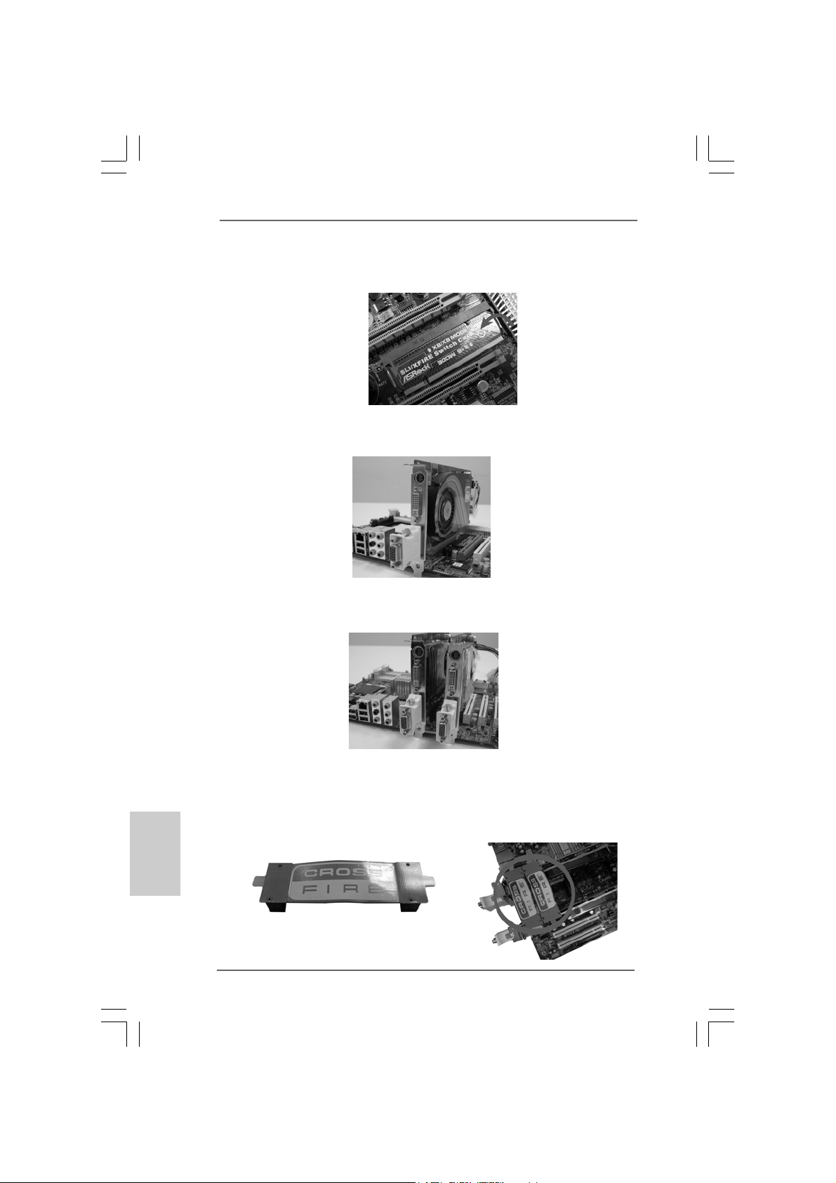
Step 4. Push the card down into the retention slot till both the retention arms firmly
hold the card into position. Also, keep away from touching the connectors
(Golden Fingers).
Step 5. Install one Radeon graphics card to PCIE2 slot. For the proper installation
procedures, plea se refer to section “Expansion Slots”.
Step 6. Install one Radeon graphics card to PCIE4 slot. For the proper installation
procedures, plea se refer to section “Expansion Slots”.
English
EnglishEnglish
EnglishEnglish
2222
22
2222
Step 7. Connect two Radeon graphics cards by installing two CrossFireTM Bridge on
CrossFireTM Bridge Interconnects on the top of Radeon graphics cards.
(CrossFireTM Bridge is provided with the graphics card you purchase, not
bundled with this motherboard. Please refer to your graphics card vendor for
details.)
CrossFireTM Bridge
ASRock P45R2000-WiFi / P45R2000 / P45TurboTwins2000 Motherboard

Step 8. Connect the DVI monitor ca ble to the DVI connector on the Ra deon graphics
card on PCIE2 slot. (Y ou may use the D VI to D-Sub adapter to convert the DVI
connector to D-Sub interfa ce, a nd then connect the D-Sub monitor cable to the
DVI to D-Sub adapter .)
Step 9. Power on your computer and boot into OS.
Step 10. Remove the ATITM driver if you have any VGA driver installed in your syste m.
The Catalyst Uninstaller is an optional download. We recommend using this
utility to uninstall any previously installed Catalyst drivers prior to installation.
Please check AMD website for ATITM driver updates.
Step 11. Install the required drivers to your system.
For Windows® XP OS:
A. ATITM recommends Windows® XP Service Pack 2 or higher to be
installed (If you have Windows® XP Service Pack 2 or higher installed
in your system, there is no need to download it again):
http://www.microsoft.com/windowsxp/sp2/default.mspx
B. You must have Microsoft .NET Framework installed prior to
downloading and installing the CATALYST Control Center. Please
check Microsoft website for details.
For Windows® VistaTM OS:
Install the CA TALYST Control Center. Please check AMD website for details.
Step 12. Restart your computer.
Step 13. Install the V GA card drivers to your system, and restart your computer.
Then you will find “A TI Catalyst Control Center” on your Windows® taskbar.
ATI Catalyst Control Center
ASRock P45R2000-WiFi / P45R2000 / P45TurboTwins2000 Motherboard
2323
23
2323
EnglishEnglish
EnglishEnglish
English

Step 14. Double-click “ATI Catalyst Control Center”. Click “View”, and select
“Advanced View”. Click “CrossFireTM”, and then set the option “Enable
CrossFireTM” to “Yes”.
View
English
EnglishEnglish
EnglishEnglish
CrossFire
TM
Although you have selected the option “Enable CrossFireTM”, the CrossFire
function may not work actually. Your computer will automatically reboot. After
restarting your computer, please confirm whether the option “Enable
CrossFireTM” in “ATI Catalyst Control Center” is selected or not; if not, please
select it again, and then you are able to enjoy the benefit of CrossFire
feature.
Enable CrossFire
TM
Step 15. You can freely enjoy the benefit of CrossFireTM feature.
* CrossFireTM appearing here is a registered trademark of ATITM Technologies Inc., and is
used only for identification or explanation and to the owners’ benefit, without intent to infringe.
* For further information of ATITM CrossFireTM technology, please check AMD website for up
dates and details.
2.6 Surround Display Feature2.6 Surround Display Feature
2.6 Surround Display Feature
2.6 Surround Display Feature2.6 Surround Display Feature
This motherboard supports Surround Display upgrade. With the external add-on PCI
Express V GA cards, you can ea sily en joy the benef its of Surround Display feature. For
the detailed instruction, plea se refer to the document at the f ollowing path in the
Support CD:
..\ Surround Display Information
TM
TM
2424
24
2424
ASRock P45R2000-WiFi / P45R2000 / P45TurboTwins2000 Motherboard

2.7 Jumpers Setup2.7 Jumpers Setup
2.7 Jumpers Setup
2.7 Jumpers Setup2.7 Jumpers Setup
The illustration shows how jumpers are
setup. When the jumper cap is placed on
pins, the jumper is “Short”. If no jumper cap
is placed on pins, the jumper is “Open”. The
illustration shows a 3-pin jumper whose pin1
and pin2 are “Short” when jumper cap is
TM
placed on these 2 pins.
Jumper Setting Description
Short Open
PS2_USB_PWR1 Short pin2, pin3 to enable
(see p.2/3 No. 5) +5VSB (standby) for PS/2
or USB wake up events.
Note: To select +5VSB, it requires 2 Amp and higher standby current provided by
power supply.
Clear CMOS Jumper
(CLRCMOS1)
(see p.2/3, No. 14)
Clear CMOSDefault
Note: CLRCMOS1 allows you to clear the data in CMOS. The data in CMOS includes
system setup information such as system password, date, time, and system
setup parameters. To clear and reset the system parameters to default setup,
please turn of f the computer and unplug the power cord from the power supply.
After waiting for 15 seconds, use a jumper ca p to short pin2 and pin3 on CLRCMOS1
for 5 seconds. However , please do not clear the CMOS right after you update the
BIOS. If you need to clear the CMOS when you just finish updating the BIOS, you
must boot up the system first, and then shut it down before you do the clearCMOS action.
FSB1 Jumper
(FSB1, 3-pin jumper, see p.2/3 No. 12)
FSB2 Jumper
(FSB2, 5-pin jumper, see p.2/3 No. 11)
Default
FSB3 Jumper
(FSB3, 5-pin jumper, see p.2/3 No. 10)
When you mount a FSB800 or FSB1066 CPU, and try to overclock to FSB1333 or
FSB1600 (by BIOS setting) you may face the problem, that D RAM frequency will be
overclocked very high. Please use jumper to force NB to be strapped at higher
frequency, so the DRAM can work at lower frequency .
ASRock P45R2000-WiFi / P45R2000 / P45TurboTwins2000 Motherboard
2525
25
2525
EnglishEnglish
EnglishEnglish
English

If you want to overclock the CPU you adopt to FSB1066 on this motherboard, you need
to adjust the jumpers. Plea se short pin4, pin5 f or FSB2 jumper and pin4, pin5 for FSB3
jumper. Otherwise, the CPU may not work properly on this motherboard. Please refer to
below jumper settings.
If you want to overclock the CPU you adopt to FSB1333 on this motherboard, you need
to adjust the jumpers. Plea se short pin3, pin4 f or FSB2 jumper and pin4, pin5 for FSB3
jumper. Otherwise, the CPU may not work properly on this motherboard. Please refer to
below jumper settings.
If you want to overclock the CPU you adopt to FSB1600 on this motherboard, you need
to adjust the jumpers. Plea se short pin3, pin4 f or FSB2 jumper and pin3, pin4 for FSB3
jumper. Otherwise, the CPU may not work properly on this motherboard. Please refer to
below jumper settings.
English
EnglishEnglish
EnglishEnglish
2626
26
2626
2.8 Onboard Headers and Connectors2.8 Onboard Headers and Connectors
2.8 Onboard Headers and Connectors
2.8 Onboard Headers and Connectors2.8 Onboard Headers and Connectors
Onboard headers and connectors are NOT jumpers. Do NOT place
jumper caps over these headers and connectors. Placing jumper
caps over the headers and connectors will cause permanent damage of the motherboard!
F DD conne ctor
(33-pin FLOPPY1)
(see p.2 No. 29 or p.3 No. 28)
Note: Make sure the red-striped side of the cable is plugged into Pin1 side of the
connector.
Primary IDE connector (Blue)
(39-pin IDE1, see p.2/3 No. 9)
connect the blue end
to the motherboard
80-conductor A TA 66/100/133 cable
Note: Please refer to the instruction of your IDE device vendor for the details.
ASRock P45R2000-WiFi / P45R2000 / P45TurboTwins2000 Motherboard
the red-striped side to
Pin1
connect the black end
to the IDE devices

Serial ATAII Connectors These six Serial A T AII (SATAII)
(SATAII_1 (Port0): connectors support SA TA data
see p.2/3, No. 20) cables for internal storage
(SATAII_2 (Port1): devices. The current SA T AII
see p.2/3, No. 21) interface allows up to 3.0 Gb/s
(SATAII_3 (Port2): data transfer rate.
see p.2/3, No. 18)
(SATAII_4 (Port3):
see p.2/3, No. 19)
(SATAII_5 (Port4):
see p.2/3, No. 17)
(SATAII_6 (Port5):
see p.2/3, No. 16)
SATAII_1 (Port0) SATAII_3 (Port2)
SATAII_2 (Port1) SATAII_4 (Port3)
SATAII_6
(Port5)
SATAII_5
(Port4)
SATAII_5 (Port4) and SATAII_6 (Port5) connectors can be used for
internal storage device or be connected to eSATAII connectors to
support eSATAII device. Please read “eSATAII Interface Introduction”
on page 32 for details about eSATAII and eSATAII installation
procedures.
eSAT AII Connectors These eSAT AII connectors
(eSATAII_TOP (Port4): support SATA data cables f or
see p.2/3, No. 3) external SATAII function. The
(eSATAII_BOTTOM (Port5): current eSAT AII interfa ce
see p.2/3, No. 2) allows up to 3.0 Gb/s data
eSATAII_BOTTOM
(Port5)
eSATAII_TOP
(Port4)
transfer rate.
Serial ATA (SA T A) Either end of the SAT A data cable
Data Cable can be connected to the SATA /
(Optional) SATAII hard disk or the SA T AII
connector on this motherboard.
Y ou can also use the SATA data
cable to connect SA T AII_5 (Port4)
or SAT AII_6 (Port5) connector a nd
eSATAII connector.
Serial ATA (SATA) Please conne ct the black end of
Power Cable SAT A power ca ble to the power
(Optional) connector on each drive. Then
connect to the SATA
HDD power connector
connect to
the power
supply
connect the white end of SATA
power cable to the power
connector of the power supply.
ASRock P45R2000-WiFi / P45R2000 / P45TurboTwins2000 Motherboard
2727
27
2727
EnglishEnglish
EnglishEnglish
English

USB 2.0 Headers Besides six default USB 2.0
(9-pin USB8_9) ports on the I/O panel, there are
(see p.2/3 No. 22) two USB 2.0 headers on this
motherboard. Each USB 2.0
header can support two USB
2.0 ports.
(9-pin USB6_7)
(see p.2/3 No. 24)
WiFi/E Header This header supports WiFi+AP
(15-pin WIFI/E) function with ASRock
(see p.2 No. 31 or p.3 No. 30) WiFi-802.11g or WiFi-802.11n
module, an easy-to-use wireless
local area network (WLAN)
adapter. It allows you to create a
wireless environment and enjoy the
convenience of wireless network
connectivity.
If you don’t plan to use WiFi+AP functin on this motherboard, this header can be
used as a 4-Pin USB 2.0 header to support one USB 2.0 port. To connect the
4-Pin USB device cable to this header, please refer to
this picture for proper installation.
English
EnglishEnglish
EnglishEnglish
2828
28
2828
DeskExpress Hot Plug Dete ction This header supports the Hot
Header Plug detection function for
(5-pin IR1) ASRock DeskExpress.
(see p.2 No. 28 or p.3 No. 27)
Internal Audio Connectors This connector allows you
(4-pin CD1) to receive stereo audio input
(CD1: see p.2 No. 34 or p.3 No. 33) from sound sources such as
CD1
a CD-ROM, D VD-ROM, TV
tuner card, or MPEG card.
ASRock P45R2000-WiFi / P45R2000 / P45TurboTwins2000 Motherboard

Front Panel Audio Hea der This is an interfa ce for front
(9-pin HD_AUDIO1) panel audio cable that allows
(see p.2 No. 32 or p.3 No. 31) convenient connection and
control of audio devices.
1. High Definition Audio supports Jack Sensing, but the panel wire on
the chassis must support HDA to function correctly. Please follow the
instruction in our manual and chassis manual to install your system.
2. If you use AC’97 audio panel, please install it to the front panel audio
header as below:
A. Connect Mic_IN (MIC) to MIC2_L.
B. Connect Audio_R (RIN) to OUT2_R and Audio_L (LIN) to OUT2_L.
C. Connect Ground (GND) to Ground (GND).
D. MIC_RET and OUT_RET are for HD audio panel only. You don’t
need to connect them for AC’97 audio panel.
E. Enter BIOS Setup Utility. Enter Advanced Settings, and then select
Chipset Configuration. Set the Front Panel Control option from
[Auto] to [Enabled].
F. Enter Windows system. Click the icon on the lower right hand
taskbar to enter Realtek HD Audio Manager.
For Windows® 2000 / XP / XP 64-bit OS:
Click “Audio I/O”, select “Connector Settings” , choose
“Disable front panel jack detection”, and save the change by
clicking “OK”.
For Windows® VistaTM / VistaTM 64-bit OS:
Click the right-top “Folder” icon , choose “Disable front
panel jack detection”, and save the change by clicking “OK”.
G. To activate the front mic.
For Windows® 2000 / XP / XP 64-bit OS:
Please select “Front Mic” as default record device.
If you want to hear your voice through front mic, please deselect "Mute"
icon in “Front Mic” of “Playback” portion.
For Windows® VistaTM / VistaTM 64-bit OS:
Go to the "Front Mic" Tab in the Realtek Control panel.
Click "Set Default Device" to make the Front Mic as the default record
device.
ASRock P45R2000-WiFi / P45R2000 / P45TurboTwins2000 Motherboard
2929
29
2929
EnglishEnglish
EnglishEnglish
English

System Panel Hea der This header a ccommodate s
(9-pin PANEL1) several system front panel
(see p.2/3 No. 23) functions.
Chassis Spea ker He ader Please connect the chassis
(4-pin SPEAKER 1) speaker to this hea der.
(see p.2/3 No. 15)
Chassis Fa n Connector Please connect a chassis fan
(3-pin CHA_FAN1) cable to this connector and
(see p.2/3 No. 25) match the black wire to the
ground pin.
CPU Fan Connector Please connect a CPU fan cable
(4-pin CPU_FAN1) to this connector and match
(see p.2/3 No. 1) the black wire to the ground pin.
1 2 3 4
Though this motherboard provides 4-Pin CPU fan (Quiet Fan) support, the 3-Pin
CPU fan still can work successfully even without the fan speed control function.
If you plan to connect the 3-Pin CPU fan to the CPU fan connector on this
motherboard, please connect it to Pin 1-3.
Pin 1-3 Connected
3-Pin Fan Installation
English
EnglishEnglish
EnglishEnglish
3030
30
3030
ATX Power Conne ctor Please connect an A TX power
(24-pin ATXPWR1) supply to this connector.
(see p.2, No. 41 or p.3 No. 40)
Though this motherboard provides 24-pin ATX power connector,
1
13
12
24
13
it can still work if you adopt a traditional 20-pin ATX power supply.
To use the 20-pin ATX power supply, please plug your
power supply along with Pin 1 and Pin 13.
20-Pin ATX Power Supply Installation
24
ASRock P45R2000-WiFi / P45R2000 / P45TurboTwins2000 Motherboard
1
12
 Loading...