

Asrock N68-GS4 FX R2.0 User Manual
N68-GS4/USB3 FX R2.0
N68-GS4 FX R2.0
User Manual
Version 1.0
Published October 2015
Copyright©2015 ASRock INC. All rights reserved.
11
1
11
Copyright Notice:Copyright Notice:
Copyright Notice:
Copyright Notice:Copyright Notice:
No part of this manual may be reproduced, transcribed, transmitted, or translated in
any language, in any form or by any means, except duplication of documentation by
the purchaser for backup purpose, without written consent of ASRock Inc.
Products and corporate names appearing in this manual may or may not be regis-
tered trademarks or copyrights of their respective companies, and are used only for
identification or explanation and to the owners’ benefit, without intent to infringe.
Disclaimer:Disclaimer:
Disclaimer:
Disclaimer:Disclaimer:
Specifications and information contained in this manual are furnished for informa-
tional use only and subject to change without notice, and should not be constructed
as a commitment by ASRock. ASRock assumes no responsibility for any errors or
omissions that may appear in this manual.
With respect to the contents of this manual, ASRock does not provide warranty of
any kind, either expressed or implied, including but not limited to the implied warran-
ties or conditions of merchantability or fitness for a particular purpose.
In no event shall ASRock, its directors, officers, employees, or agents be liable for
any indirect, special, incidental, or consequential damages (including damages for
loss of profits, loss of business, loss of data, interruption of business and the like),
even if ASRock has been advised of the possibility of such damages arising from any
defect or error in the manual or product.
This device complies with Part 15 of the FCC Rules. Operation is subject to the
following two conditions:
(1) this device may not cause harmful interference, and
(2) this device must accept any interference received, including interference that
may cause undesired operation.
CALIFORNIA, USA ONLY
The Lithium battery adopted on this motherboard contains Perchlorate, a toxic
substance controlled in Perchlorate Best Management Practices (BMP) regulations
passed by the California Legislature. When you discard the Lithium battery in
California, USA, please follow the related regulations in advance.
“Perchlorate Material-special handling may apply, see
www.dtsc.ca.gov/hazardouswaste/perchlorate”
ASRock Website: http://www.asrock.com
22
2
22

ContentsContents
Contents
ContentsContents
1.1.
IntroductionIntroduction
1.
Introduction
1.1.
IntroductionIntroduction
1.1 Package Contents ..................................................................... 5
1.2 Specifications ............................................................................ 6
1.3 Motherboard Layout ................................................................... 10
1.4 I/O Panel .................................................................................... 12
2.2.
InstallationInstallation
2.
Installation
2.2.
InstallationInstallation
Pre-installation Precautions ................................................................ 14
2.1 CPU Installation ......................................................................... 15
2.2 Installation of CPU Fan and Heatsink ......................................... 15
2.3 Installation of Memory Modules (DIMM) .................................... 16
2.4 Expansion Slots (PCI and PCI Express Slots) .................................. 17
2.5 Jumpers Setup .......................................................................... 18
2.6 Onboard Headers and Connectors ............................................. 19
3.3.
BIOS SBIOS S
3.
BIOS S
3.3.
BIOS SBIOS S
3.1 Introduction ................................................................................ 22
3.2 Main Screen .............................................................................. 23
3.3 OC Tweaker Screen .. ................................................................. 25
3.4 Advanced Screen ....................................................................... 29
3.5 Hardware Health Event Monitoring Screen ................................. 37
3.6 Boot Screen .............................................................................. 38
3.7 Security Screen ......................................................................... 39
3.8 Exit Screen ................................................................................ 40
ETUP UTILITYETUP UTILITY
ETUP UTILITY
ETUP UTILITYETUP UTILITY
3.1.1 BIOS Menu Bar ............................................................... 22
3.1.2 Navigation Keys .............................................................. 23
3.4.1 CPU Configuration ........................................................... 30
3.4.2 Chipset Configuration ...................................................... 31
3.4.3 ACPI Configuration .......................................................... 32
3.4.4 Storage Configuration ...................................................... 33
3.4.5 PCIPnP Configuration ...................................................... 34
3.4.6 Super IO Configuration .................................................... 35
3.4.7 USB Configuration ........................................................... 36
3.6.1 Boot Settings Configuration ............................................. 38
......................................................................................................................
...........................................................
......................................................................................................................
..........................................................................................................................
.............................................................
..........................................................................................................................
....................................................................................................
..................................................
....................................................................................................
5 5
5
5 5
14 14
14
14 14
22 22
22
22 22
33
3
33

4.4.
Software SupportSoftware Support
4.
Software Support
4.4.
Software SupportSoftware Support
4.1 Install Operating System ........................................................... 41
4.2 Support CD Information .............................................................. 41
4.2.1 Running Support CD ........................................................ 41
4.2.2 Drivers Menu ...... ......... .................. ......... .................. ....... 41
4.2.3 Utilities Menu .................................................................. 41
4.2.4 Contact Information.......................................................... 41
......................................................................................................
...................................................
......................................................................................................
41 41
41
41 41
44
4
44
1.1.
IntroductionIntroduction
1.
Introduction
1.1.
IntroductionIntroduction
Thank you for purchasing ASRock N68-GS4/USB3 FX R2.0 / N68-GS4 FX R2.0
motherboard, a reliable motherboard produced under ASRock’s consistently stringent
quality control. It delivers excellent performance with robust design conforming to ASRock’s
commitment to quality and endurance.
In this manual, chapter 1 and 2 contain introduction of the motherboard and step-by-step
guide to the hardware installation. Chapter 3 and 4 contain the configuration guide to
BIOS setup and information of the Support CD.
Because the motherboard specifications and the BIOS software might be
updated, the content of this manual will be subject to change without
notice. In case any modifications of this manual occur, the updated
version will be available on ASRock website without further notice. You
may find the latest VGA cards and CPU support lists on ASRock website
as well. ASRock website
If you require technical support related to this motherboard, please visit
our website for specific information about the model you are using.
www.asrock.com/support/index.asp
http://www.asrock.com
1.1 P1.1 P
1.1 P
1.1 P1.1 P
ASRock N68-GS4/USB3 FX R2.0 / N68-GS4 FX R2.0 Motherboard
(Micro ATX Form Factor)
ASRock N68-GS4/USB3 FX R2.0 / N68-GS4 FX R2.0X Quick Installation Guide
ASRock N68-GS4/USB3 FX R2.0 / N68-GS4 FX R2.0 Support CD
2 x Serial ATA (SATA) Data Cables (Optional)
1 x I/O Panel Shield
ackack
age Contentsage Contents
ack
age Contents
ackack
age Contentsage Contents
55
5
55
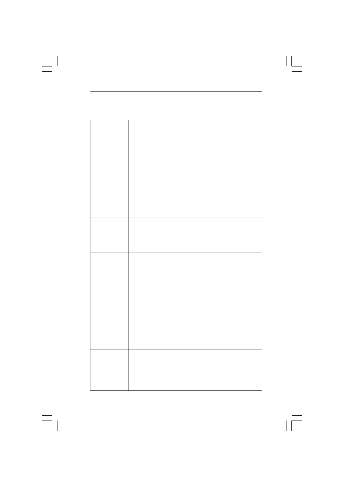
1.2 Specifications1.2 Specifications
1.2 Specifications
1.2 Specifications1.2 Specifications
Platform - Micro ATX Form Factor
- Solid Capacitor design
CPU - Support for Socket AM3+ processors
- Support for AM3 processors: AMD PhenomTM II X6 / X4 / X3 /
X2 (except 920 / 940) / Athlon II X4 / X3 / X2 / Sempron
processors (see CAUTION 1)
- Supports 8-Core CPU
- 4 + 1 Power Phase design
- Supports UCC feature (Unlock CPU Core) (see CAUTION 2)
- Supports AMD’s Cool ‘n’ QuietTM Technology
- FSB 1000 MHz (2.0 GT/s)
- Supports Untied Overclocking Technology
- Supports Hyper-Transport Technology
Chipset - NVIDIA
Memory - Dual Channel DDR3 Memory Technology
Expansion Slot - 1 x PCI Express x16 Slot
Graphics - Integrated NVIDIA
Audio - 7.1 CH HD Audio (Realtek ALC887 Audio Codec)
LAN - Gigabit LAN 10/100/1000 Mb/s
®
GeForce 7025 / nForce 630a
- 2 x DDR3 DIMM Slots
- Support DDR3 1866/1600/1333/1066 non-ECC, un-buffered
memory (see CAUTION 3)
- Max. capacity of system memory: 16GB (see CAUTION 4)
- 1 x PCI Express x1 Slot
- 1 x PCI Slot
- DX9.0 VGA, Pixel Shader 3.0
- Max. shared memory 256MB
- Supports D-Sub with max. resolution up to 1920x1440
@ 60Hz
* To configure 7.1 CH HD Audio, it is required to use an HD front
panel audio module and enable the multi-channel audio feature
through the audio driver.
- Supports Surge Protection (ASRock Full Spike Protection)
- ELNA Audio Caps
- Giga PHY Realtek RTL8211E
- Supports Wake-On-LAN
- Supports Lightning/ESD Protection (ASRock Full Spike
Protection)
- Supports Energy Efficient Ethernet 802.3az
®
GeForce 7025 graphics
66
6
66

- Supports PXE
Rear Panel I/O N68-GS4/USB3 FX R2.0:
- 1 x PS/2 Mouse Port
- 1 x PS/2 Keyboard Port
- 1 x Serial Port: COM1
- 1 x D-Sub Port
- 2 x USB 2.0 Ports (Supports ESD Protection (ASRock Full
Spike Protection))
- 2 x USB 3.0 Ports (Etron EJ188H) (PCIE GEN1) (Supports
ESD Protection (ASRock Full Spike Protection))
- 1 x RJ-45 LAN Port with LED (ACT/LINK LED and SPEED LED)
- HD Audio Jacks: Line in / Front Speaker / Microphone
Rear Panel I/O N68-GS4 FX R2.0:
- 1 x PS/2 Mouse Port
- 1 x PS/2 Keyboard Port
- 1 x Serial Port: COM1
- 1 x D-Sub Port
- 4 x USB 2.0 Ports (Supports ESD Protection (ASRock Full
Spike Protection))
- 1 x RJ-45 LAN Port with LED (ACT/LINK LED and SPEED LED)
- HD Audio Jacks: Line in / Front Speaker / Microphone
Storage - 4 x SATA2 3.0 Gb/s Connectors, support RAID (RAID 0,
RAID 1, RAID 0+1, RAID 5 and JBOD), NCQ and Hot Plug
Connector - 1 x Print Port Header
- 1 x Chassis Intrusion Header
- 1 x CPU Fan Connector (4-pin)
- 1 x Chassis Fan Connector (3-pin)
- 1 x 24 pin ATX Power Connector
- 1 x 8 pin 12V Power Connector
- 1 x Front Panel Audio Connector
- 2 x USB 2.0 Headers (Support 4 USB 2.0 ports) (Supports ESD
Protection (ASRock Full Spike Protection))
- 1 x USB 3.0 Header by Etron EJ188H (PCIE GEN1) (Supports
2 USB 3.0 ports) (Supports ESD Protection (ASRock Full Spike
Protection)) (for N68-GS4/USB3 FX R2.0 only)
BIOS Feature - AMI Legal BIOS
- Supports "Plug and Play"
- ACPI 1.1 Compliant wake up events
- Supports jumperfree
- SMBIOS 2.3.1 support
- CPU, VCCM, NB Voltage multi-adjustment
77
7
77
Hardware - CPU temperature sensing
Monitor - Chassis temperature sensing
- CPU Fan Tachometer
- Chassis Fan Tachometer
- CPU Quiet Fan
- CASE OPEN detection
- Voltage monitoring: +12V, +5V, +3.3V, Vcore
OS - Microsoft
®
Windows® 10 32-bit / 10 64-bit / 8.1 32-bit / 8.1
64-bit / 8 32-bit / 8 64-bit / 7 32-bit / 7 64-bit / VistaTM 32-bit /
TM
Vista
64-bit / XP 32-bit / XP 64-bit (see CAUTION 5)
Certifications - FCC, CE, WHQL
- ErP/EuP ready (ErP/EuP ready power supply is required)
* For detailed product information, please visit our website: http://www.asrock.com
WA R NING
Please realize that there is a certain risk involved with overclocking, including adjusting
the setting in the BIOS, applying Untied Overclocking Technology, or using the third-
party overclocking tools. Overclocking may affect your system stability, or even
cause damage to the components and devices of your system. It should be done at
your own risk and expense. We are not responsible for possible damage caused by
overclocking.
88
8
88
CAUTION!
1. This motherboard supports CPU up to 140W. Please refer to our website for
CPU support list. ASRock website
2. ASRock UCC (Unlock CPU Core) feature simplifies AMD CPU activation. As
long as a simple switch of the BIOS option “ASRock UCC”, you can unlock
the extra CPU core to enjoy an instant performance boost. When UCC
feature is enabled, the dual-core or triple-core CPU will boost to the quad-
core CPU, and some CPU, including quad-core CPU, can also increase L3
cache size up to 6MB, which means you can enjoy the upgrade CPU perfor-
mance with a better price. Please be noted that UCC feature is supported
with AM3/AM3+ CPU only, and in addition, not every AM3/AM3+ CPU can
support this function because some CPU’s hidden core may be
malfunctioned.
3. Whether 1866/1600MHz memory speed is supported depends on the
AM3/AM3+ CPU you adopt. If you want to adopt DDR3 1866/1600 memory
module on this motherboard, please refer to the memory support list on
our website for the compatible memory modules.
ASRock website
4. Due to the operating system limitation, the actual memory size may be
less than 4GB for the reservation for system usage under Windows® 10
/ 8.1 / 8 / 7 / Vista
such limitation.
5. This motherboard does not support RAID mode under Windows® 10
32-bit / 10 64-bit / 8.1 32-bit / 8.1 64-bit. This motherboard does not
support RAID mode with HDDs of 3TB and above.
http://www.asrock.com
TM
/ XP. For Windows® OS with 64-bit CPU, there is no
http://www.asrock.com
99
9
99
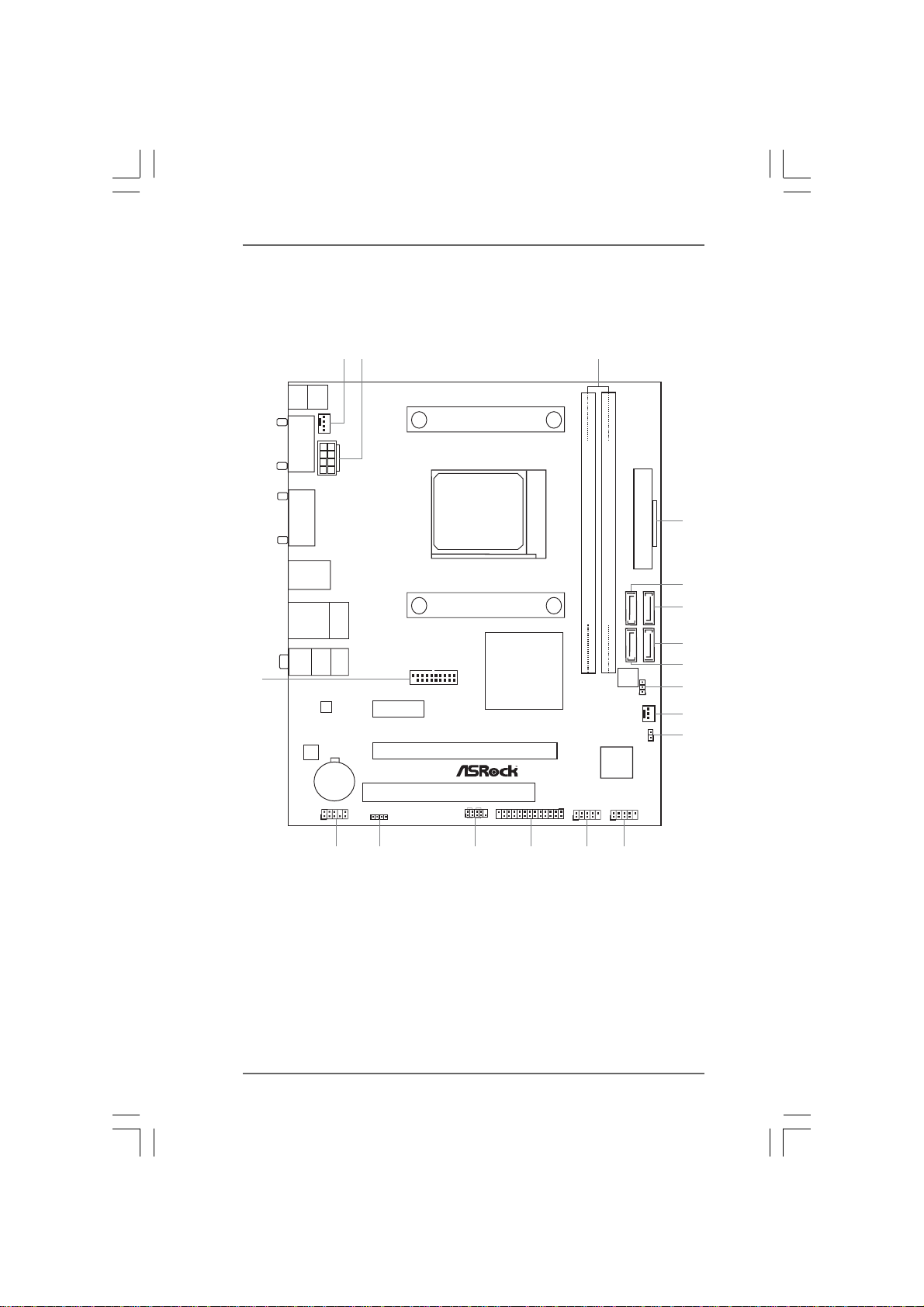
1.3 Motherboard Layout1.3 Motherboard Layout
1.3 Motherboard Layout
1.3 Motherboard Layout1.3 Motherboard Layout
N68- N68-
N68-
N68- N68-
GS4/USB3 FX R2.0:GS4/USB3 FX R2.0:
GS4/USB3 FX R2.0:
GS4/USB3 FX R2.0:GS4/USB3 FX R2.0:
3
FSB800
4
Keyboard
PS2
COM1
VGA1
Mouse
PS2
CPU_FAN1
2
1
ATX12V1
SOCKET AM3
ATXPWR1
USB 3.0
T:USB3
B: USB4
USB 2.0
Top:
T:USB3
RJ-45
B: USB4
Bottom:
MIC IN
Top:
LINE IN
Center:
FRONT
18
LAN
PHY
USB3_1_2
PCIE1
NVIDIA
GeForce
7025 /
nForce
630a
N68-GS4/USB3 FX
AUDIO
CODEC
CMOS
BATTERY
HD_AUDIO1
1
1
SPEAKER1
PCI1
PCIE2
PANEL1
PLED PWRBTN
1
11
HDLED RESET
1
LPT1
DDR3_B1 (64bit, 240-pin module)
DDR3_A1 (64bit, 240-pin module)
(PORT1.1) (PORT0.1)
(PORT1.0) (PORT0.0)
SATAII_4 SATAII_2
SATAII_3 SATAII_1
BIOS
ROM
CLRCMOS1
1
CHA_FAN1
RoHS
Super
I/O
US7_8
USB5_6
1
1
5
6
7
8
9
10
CI1
11
1
17
16
15
14
1213
1 CPU Fan Connector (CPU_FAN1) 10 Chassis Fan Connector (CHA_FAN1)
2 ATX 12V Power Connector (ATX12V1) 11 Chassis Intrusion Header (CI1)
3 2 x 240-pin DDR3 DIMM Slots 12 USB 2.0 Header (USB7_8)
(Dual Channel: DDR3_A1, DDR3_B1) 13 USB 2.0 Header (USB5_6)
4 ATX Power Connector (ATXPWR1) 14 Print Port Header (LPT1)
5 SATA2 Connector (SATAII_2 (PORT 0.1)) 15 System Panel Header (PANEL1)
6 SATA2 Connector (SATAII_1 (PORT 0.0)) 16 Chassis Speaker Header (SPEAKER1)
7 SATA2 Connector (SATAII_3 (PORT 1.0)) 17 Front Panel Audio Header (HD_AUDIO1)
8 SATA2 Connector (SATAII_4 (PORT 1.1)) 18 USB 3.0 Header (USB3_1_2)
9 Clear CMOS Jumper (CLRCMOS1)
1010
10
1010
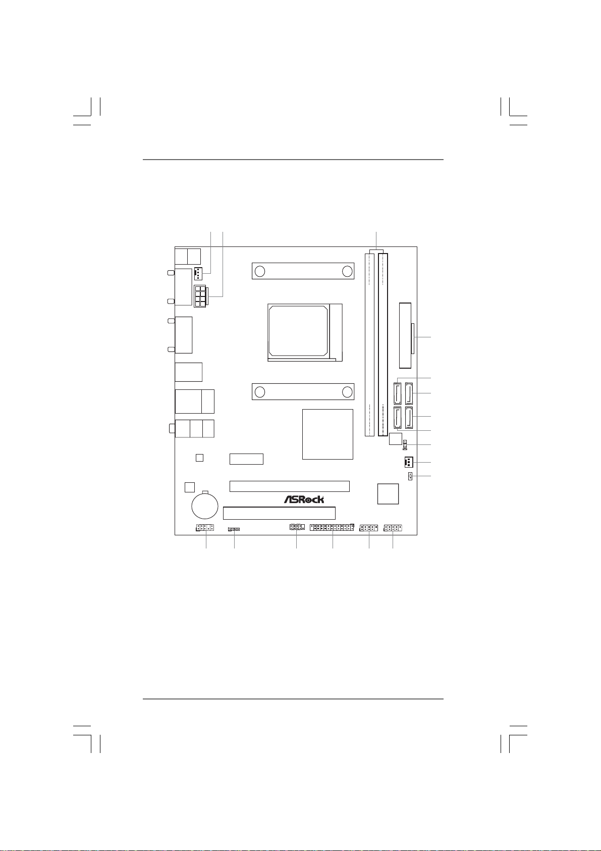
N68- N68-
N68-
N68- N68-
GS4 FX R2.0:GS4 FX R2.0:
GS4 FX R2.0:
GS4 FX R2.0:GS4 FX R2.0:
Keyboard
PS2
COM1
VGA1
USB 2.0
T:USB1
B: USB2
USB 2.0
T:USB3
B: USB4
Bottom:
MIC IN
AUDIO
CODEC
Mouse
PS2
CPU_FAN1
ATX12V1
Top:
RJ-45
Center:
FRONT
LAN
PHY
CMOS
BATTERY
HD_AUDIO1
1
2
1
3
SOCKET AM3
FSB800
DDR3_B1 (64bit, 240-pin module)
DDR3_A1 (64bit, 240-pin module)
(PORT1.1) (PORT0.1)
Super
I/O
1
SATAII_4 SATAII_2
BIOS
ROM
CLRCMOS1
(PORT1.0) (PORT0.0)
SATAII_3 SATAII_1
1
CHA_FAN1
Top:
LINE IN
NVIDIA
GeForce
7025 /
nForce
1
PCIE1
SPEAKER1
N68-GS4 FX
PCIE2
PCI1
PANEL1
PLED PWRBTN
1
11
HDLED RESET
630a
LPT1
1
1
RoHS
USB5_6 US7_8
ATXPWR1
CI1
1
4
5
6
7
8
9
10
11
17
16
15
14
1213
1 CPU Fan Connector (CPU_FAN1) 9 Clear CMOS Jumper (CLRCMOS1)
2 ATX 12V Power Connector (ATX12V1) 10 Chassis Fan Connector (CHA_FAN1)
3 2 x 240-pin DDR3 DIMM Slots 11 Chassis Intrusion Header (CI1)
(Dual Channel: DDR3_A1, DDR3_B1) 12 USB 2.0 Header (USB7_8)
4 ATX Power Connector (ATXPWR1) 13 USB 2.0 Header (USB5_6)
5 SATA2 Connector (SATAII_2 (PORT 0.1)) 14 Print Port Header (LPT1)
6 SATA2 Connector (SATAII_1 (PORT 0.0)) 15 System Panel Header (PANEL1)
7 SATA2 Connector (SATAII_3 (PORT 1.0)) 16 Chassis Speaker Header (SPEAKER1)
8 SATA2 Connector (SATAII_4 (PORT 1.1)) 17 Front Panel Audio Header (HD_AUDIO1)
1111
11
1111
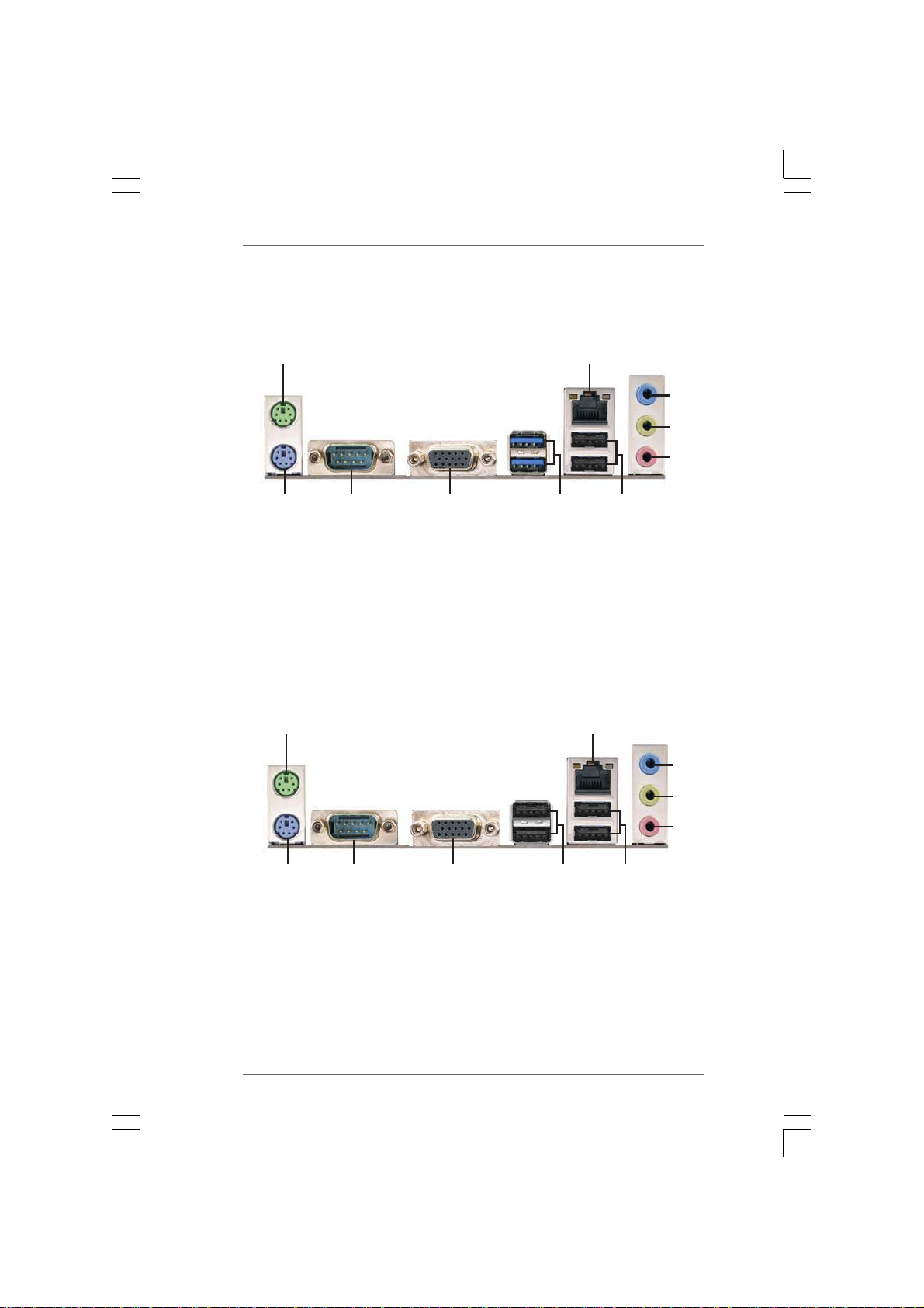
1.4 I/O P1.4 I/O P
1.4 I/O P
1.4 I/O P1.4 I/O P
N68- N68-
N68-
N68- N68-
anelanel
anel
anelanel
GS4/USB3 FX R2.0:GS4/USB3 FX R2.0:
GS4/USB3 FX R2.0:
GS4/USB3 FX R2.0:GS4/USB3 FX R2.0:
1
10
1 PS/2 Mouse Port (Green) 6 USB 2.0 Ports (USB34)
2 RJ-45 Port* 7 USB 3.0 Ports (USB3_34)
3 Line In (Light Blue)** 8 D-Sub Port
4 Front Speaker (Lime)** 9 COM Port
5 Microphone (Pink)** 10 PS/2 Keyboard Port (Purple)
N68- N68-
N68-
N68- N68-
9
GS4 FX R2.0:GS4 FX R2.0:
GS4 FX R2.0:
GS4 FX R2.0:GS4 FX R2.0:
8
1
2
7
2
3
4
5
6
3
4
10
1 PS/2 Mouse Port (Green) 6 USB 2.0 Ports (USB34)
2 RJ-45 Port* 7 USB 2.0 Ports (USB12)
3 Line In (Light Blue)** 8 D-Sub Port
4 Front Speaker (Lime)** 9 COM Port
5 Microphone (Pink)** 10 PS/2 Keyboard Port (Purple)
9
8
1212
12
1212
7
6
5
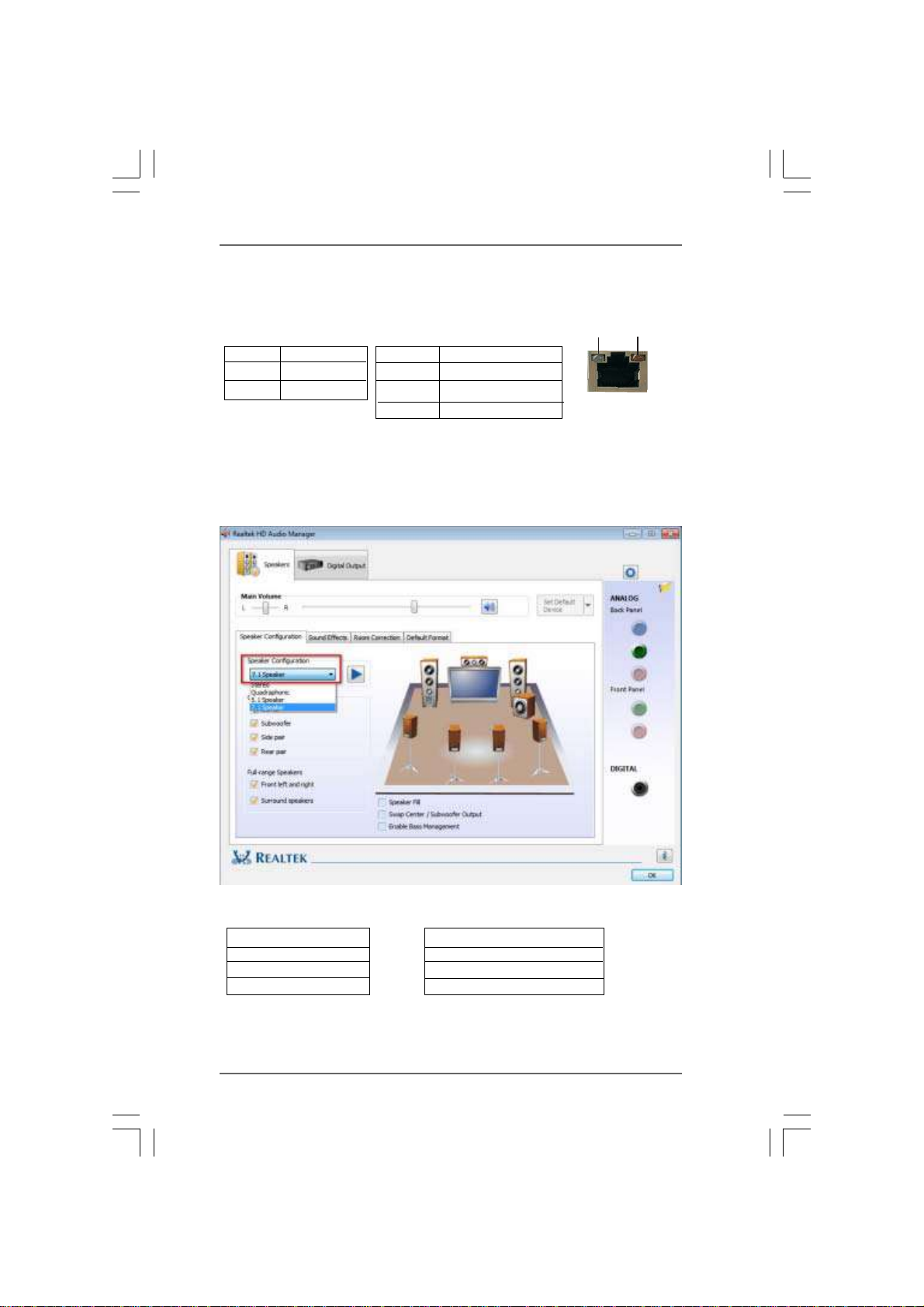
* There are two LED next to the LAN port. Please refer to the table below for the LAN port LED
indications.
Activity/Link LED SPEED LED
Status Description Status Description
LAN Port LED Indications
ACT/LINK
LED
SPEED
LED
Off No Activity Off 10Mbps connection
Blinking Data Activity Orange 100Mbps connection
Green 1Gbps connection
** To configure 7.1 CH HD Audio, it is required to use an HD front panel audio module and
enable the multi-channel audio feature through the audio driver.
Please set Speaker Configuration to “7.1 Speaker” in the Realtek HD Audio Manager.
LAN Port
Function of the Audio Ports in 7.1-channel Configuration
Port Function
Light Blue (Rear panel) Rear Speaker Out
Lime (Rear panel) Front Speaker Out
Pink (Rear panel) Central /Subwoofer Speaker Out
Lime (Front panel) Side Speaker Out
1313
13
1313
 Loading...