

ASROCK IMB-192 User Manual

1
IMB-192
User Manual
Version 1.0
Published July 2017
Copyright©2017 ASRock INC. All rights reserved.

2
Version 1.0
Published July 2017
Copyright©2017 ASRock INC. All rights reserved.
Copyright Notice:
No part of this documentation may be reproduced, transcribed, transmitted, or
translated in any language, in any form or by any means, except duplication of
documentation by the purchaser for backup purpose, without written consent of
ASRock Inc.
Products and corporate names appearing in this documentation may or may not
be registered trademarks or copyrights of their respective companies, and are used
only for identication or explanation and to the owners’ benet, without intent to
infringe.
Disclaimer:
Specications and information contained in this documentation are furnished for
informational use only and subject to change without notice, and should not be
constructed as a commitment by ASRock. ASRock assumes no responsibility for
any errors or omissions that may appear in this documentation.
With respect to the contents of this documentation, ASRock does not provide
warranty of any kind, either expressed or implied, including but not limited to
the implied warranties or conditions of merchantability or tness for a particular
purpose.
In no event shall ASRock, its directors, ocers, employees, or agents be liable for
any indirect, special, incidental, or consequential damages (including damages for
loss of prots, loss of business, loss of data, interruption of business and the like),
even if ASRock has been advised of the possibility of such damages arising from any
defect or error in the documentation or product.
is device complies with Part 15 of the FCC Rules. Operation is subject to the following
two conditions:
(1) this device may not cause harmful interference, and
(2) this device must accept any interference received, including interference that
may cause undesired operation.
CALIFORNIA, USA ONLY
e Lithium battery adopted on this motherboard contains Perchlorate, a toxic substance
controlled in Perchlorate Best Management Practices (BMP) regulations passed by the
California Legislature. When you discard the Lithium battery in California, USA, please
follow the related regulations in advance.
“Perchlorate Material-special handling may apply, see www.dtsc.ca.gov/hazardouswaste/
perchlorate”
ASRock Website: http://www.asrock.com
3
CAUTION:
RISK OF EXPLOSION IF BATTERY IS REPLACED BY AN INCORRECT TYPE.
DISPOSE OF USED BATTERIES ACCORDING TO THE INSTRUCTIONS.
e terms HDMI™ and HDMI High-Denition Multimedia Interface, and the HDMI
logo are trademarks or registered trademarks of HDMI Licensing LLC in the United
States and other countries.

4
Contents
1 Introduction ....................................................... 5
1.1 Package Contents ......................................................... 5
1.2 Specications ................................................................. 6
1.3 Motherboard Layout ....................................................... 8
1.4 I/O Panel ........................................................................ 10
2 Installation ......................................................... 11
2.1 Screw Holes ................................................................... 11
2.2 Pre-installation Precautions ........................................... 11
2.3 Installation of Memory Modules (SO-DIMM) .................. 12
2.4 Expansion Slots ............................................................ 13
2.5 Jumpers Setup ............................................................... 14
2.6 Onboard Headers and Connectors ................................ 16
3 UEFI SETUP UTILITY ......................................... 21
3.1 Introduction .................................................................... 21
3.1.1 UEFI Menu Bar .................................................... 21
3.1.2 Navigation Keys ................................................... 22
3.2 Main Screen ................................................................... 22
3.3 Advanced Screen ........................................................... 23
3.3.1 CPU Conguration ............................................... 24
3.3.2 Chipset Conguration........................................... 26
3.3.3 Storage Conguration .......................................... 28
3.3.4 Super IO Conguration ........................................ 29
3.3.5 ACPI Conguration............................................... 30
3.3.6 USB Conguration ............................................... 31
3.3.7 Trusted Computing ............................................... 32
3.4 Hardware Health Event Monitoring Screen ................... 33
3.5 Security Screen ............................................................. 34
3.6 Boot Screen ................................................................... 35
3.7 Exit Screen .................................................................... 37
4 Software Support .............................................. 38
4.1 Install Operating System ................................................ 38
4.2 Support CD Information ................................................. 38
4.2.1 Running Support CD ............................................ 38
4.2.2 Drivers Menu ........................................................ 38
4.2.3 Utilities Menu........................................................ 38
4.2.4 Contact Information .............................................. 38
5
Chapter 1: Introduction
Thank you for purchasing ASRock IMB-192 motherboard, a reliable motherboard
produced under ASRock’s consistently stringent quality control. It delivers excellent
performance with robust design conforming to ASRock’s commitment to quality and
endurance.
In this manual, chapter 1 and 2 contain introduction of the motherboard and step-
by-step guide to the hardware installation. Chapter 3 and 4 contain the conguration
guide to BIOS setup and information of the Support CD.
Because the motherboard specications and the BIOS software might be
updated, the content of this manual will be subject to change without no-
tice. In case any modications of this manual occur, the updated version
will be available on ASRock website without further notice. You may nd
the latest VGA cards and CPU support lists on ASRock website as well.
ASRock website http://www.asrock.com
If you require technical support related to this motherboard, please visit
our website for specic information about the model you are using.
www.asrock.com/support/index.asp
1.1 Package Contents
ASRock IMB-192 Motherboard
(Mini-ITX Form Factor: 6.7-in x 6.7-in, 17.0 cm x 17.0 cm)
ASRock IMB-192 Driver CD
ASRock IMB-192 Jumper setting instruction
1 x I/O Panel Shield
6
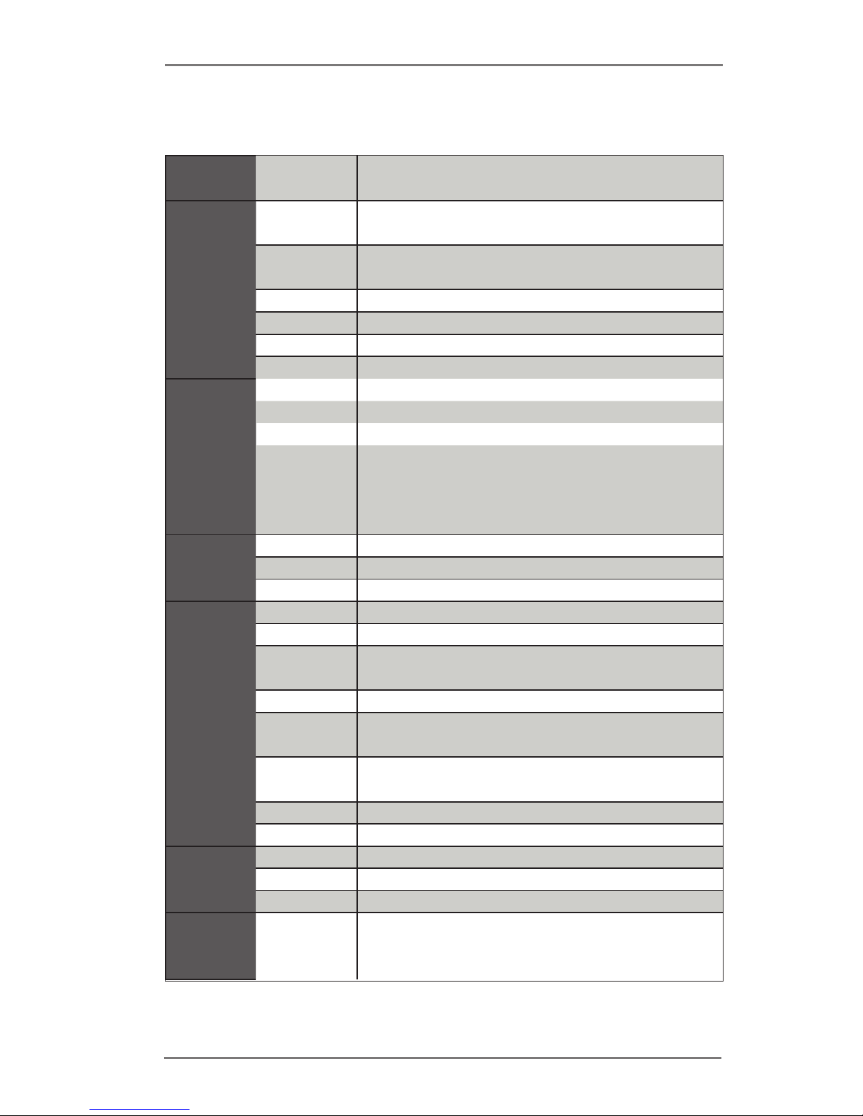
1.2 Specications
Form
Factor
Dimensions Mini-ITX (6.7-in x 6.7-in)
Processor
System
CPU
Socket LGA1151 for Intel® Core i7 / i5 / i3 /
Pentium® / Celeron® (Skylake)
Core
Number
(By CPU, Max 4)
Max Speed (By CPU)
L3 Cache (By CPU)
Chipset Intel® H110
BIOS UEFI
Expansion
Slot
PCIe 1 x PCI Express 3.0 x 4 Slot
Mini-PCIe 0
mSATA 0
M.2
1 x M.2 Socket (Key E), supports type 2230
WiFi/BT module
1 x M.2 Socket (Key M), supports type
2242/2260 (SATA only)
Memory
Technology Dual Channel DDR4 2133 MHz
Max. 32GB
Socket 2 x SO-DIMM
Graphics
Controller Intel® HD Graphics 510/530
VRAM Shared Memory
VGA
Supports max resolution up to 1920x1200 @
60Hz
DVI No
LVDS
Supports max resolution up to 1920 x
1200@60Hz @ 60Hz
HDMI
Supports max resolution up to 4K x 2K
(4096x2160) @ 24Hz /(3840x2160) @ 30Hz
DisplayPort No
Multi Display Dual
Ethernet
Ethernet 10/100/1000 Mbps
Controller 1 x Intel® I219V
Connector 1 x RJ-45
SATA
Max Data
Transfer
Rate
SATA3 (6.0Gb/s)
7
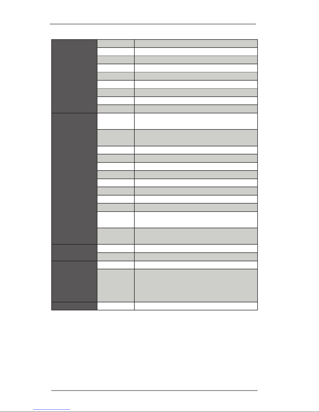
Rear I/O
VGA 1
DVI 0
HDMI 1
DisplayPort 0
Ethernet 1
USB 4 x USB 3.0
Audio 2 (Mic-in, Line-out)
Serial 0
PS/2 0
Internal
Connector
USB
5 x USB 2.0 (2 x 2.54 pitch header, 1 x
Type A)
LVDS/
inverter
1/1
VGA 0
Serial 2 x 2.0 pitch header RS-232
SATA 2 x SATA3 (6.0Gb/s)
mPCIe 0
Parallel 0
mSATA 0
IrDA 0
GPIO 8-bit 0
SATA PWR
Output Con
1
Speaker
Header
1
Watchdog
Timer
Output From Super I/O to drag RESETCON#
Interval 256 segments, 0,1,2…255sec/min
Power
Requirements
Input PWR 19V phone jack DC-In
Power On
AT/ATX Supported
AT : Directly PWR on as power input ready
ATX : Press button to PWR on after power
input ready
Environment Temperature 0ºC – 60ºC
8
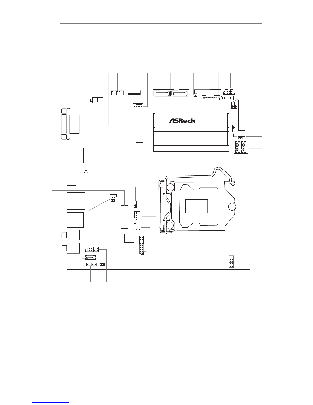
1.3 Motherboard Layout
Mic In
BIO S
Chi p
1
USB2_1 _2
1
HD_AUD IO1
CHA_FAN 1
PCIE1
DC_J ACK1
LVDS1
1
LPC1
1
CLRMOS 1
1
USB 3 .0
T: US B1
B: US B2
Line O ut
TO_UPS1
1
BLT_CTL 1
PANEL1
HDLED R ESET
PLED PWRBTN
1
COM2
COM1
1
M2_2
SATA3_0 SATA3_1
LAN1
HDMI 1
SPEAKE R1
1
Indu stri al
1
BUZZ2
M2
VGA1
USB 3 .0
T: US B3
B: US B4
1
MONITOR _SWITCH1
1
BL11Bl2
SATA_POW 1
1
PNL_PWR 1
1
BKT_PWR 1
PWR_CO M1
1
1
1
USB2_4 _5
SPDIF1
1
1
CI1
1
CI2
1
BKT_CON 1
CPU_FAN 1
1
PWR_JP1
1
CLRMOS2
IMB-192
13
12
11
1
3
2
4
5
6
7
8
10
16
17
15
18
21
22
19
20
23
24
25
26
28
29
27
14
9
1
PWR_CO M2

9
1 : Clear CMOS Header
2 : 2-pin UPS Module Power Input Connector
3 : M.2 (Key-M)
4 :
USB2.0 Header (USB2_1_2)
5 :
USB2.0 Port
6 :
4-Pin Chassis FAN Connector (+12V)
7 : SATA3 Connectors (SATA3_0, SATA3_1)
8 : Monitor Switch Header
9 : SATA Power Output Connector
10 : Backlight Control (BLT_CTL1)
11 :
System Panel Header
12 : BL1, BL2
13 :
Panel Power Select (PNL_PWR1)
14 : Backlight Power Select (BKT_PWR1)
15 : LVDS Panel Connector
16 : COM Port Pin9 PWR Setting Jumpers
PWR_COM1 (For COM Port1)
PWR_COM2 (For COM Port2)
17 : COM Port Headers (COM1, COM2) (RS232)
18 :
USB2.0 Header (USB2_4_5)
19 :
4-Pin CPU FAN Connector (+12V)
20 : Clear CMOS Jumper
21 : LPC Header
22 : ATX/AT Mode Jumper (PWR_JP1)
23 :
Front Panel Audio Header
24 : Buzzer
25 : SPDIF Header
26 : 3W Audio AMP Output Wafer
27 : Chassis Intrusion Headers
(CI1, CI2)
28 : M.2 (Key-E)
29 : Backlight Control Select (BKT_CON1)
10
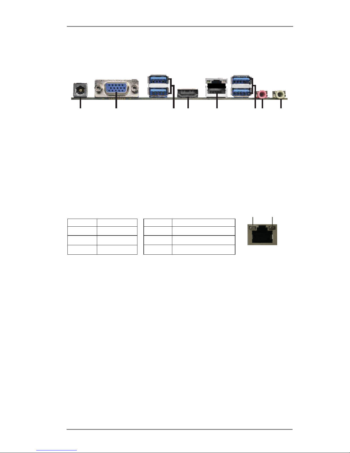
1.4 I/O Panel
* There are two LED next to the LAN port. Please refer to the table below for the LAN port LED
indications.
LAN Port LED Indications
Activity/Link LED SPEED LED
Status Description Status Description
Off No Link Off 10Mbps connection
Blinking Data Activity Orange 100Mbps connection
On Link Green 1Gbps connection
ACT/LINK
LED
SPEED
LED
LAN Port
1 DC Jack
2 D-Sub Port (VGA1)
3 USB 3.0 Ports (USB3_1_2)
4 HDMI Port (HDMI1)
5 LAN RJ-45 Port*
6 USB 3.0 Ports (USB3_3_4)
7 Microphone (Pink)
8 Line out (Lime)
6
1
2
4
3
5
8
7
11
Chapter 2: Installation
This is a Mini-ITX form factor (6.7” x 6.7”, 17.0 x 17.0 cm) motherboard. Before you
install the motherboard, study the conguration of your chassis to ensure that the
motherboard ts into it.
Make sure to unplug the power cord before installing or removing the
motherboard. Failure to do so may cause physical injuries to you and
damages to motherboard components.
2.1 Screw Holes
Place screws into the holes to secure the motherboard to the chassis.
Do not over-tighten the screws! Doing so may damage the motherboard.
2.2 Pre-installation Precautions
Take note of the following precautions before you install motherboard components
or change any motherboard settings.
1. Unplug the power cord from the wall socket before touching any component.
2. To avoid damaging the motherboard components due to static electricity,
NEVER place your motherboard directly on the carpet or the like. Also
remember to use a grounded wrist strap or touch a safety grounded object
before you handle components.
3. Hold components by the edges and do not touch the ICs.
4. Whenever you uninstall any component, place it on a grounded antistatic pad or
in the bag that comes with the component.
Before you install or remove any component, ensure that the power is
switched off or the power cord is detached from the power supply.
Failure to do so may cause severe damage to the motherboard, peripherals,
and/or components.
12
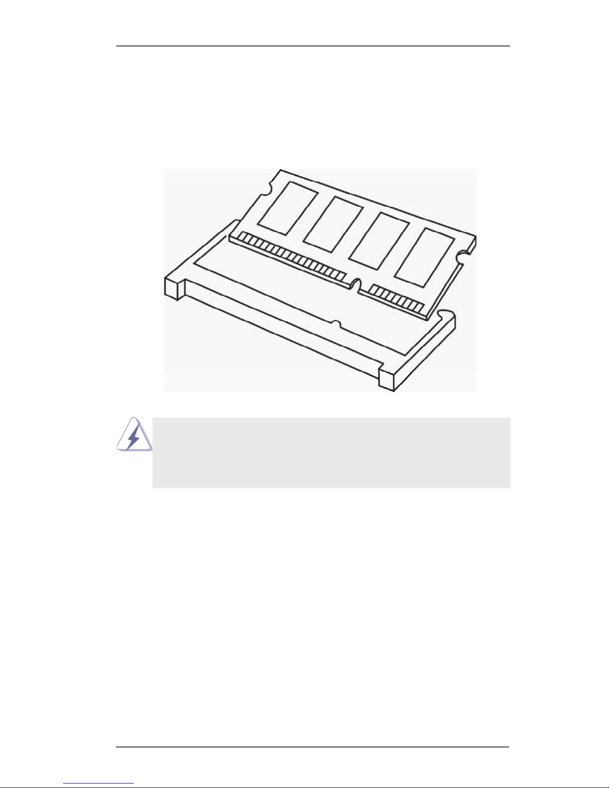
2.3 Installation of Memory Modules (SO-DIMM)
IMB-192 provides two 204-pin DDR4 (Double Data Rate 4) SO-DIMM slots.
Step 1. Align a SO-DIMM on the slot such that the notch on the SO-DIMM
matches the break on the slot.
1. The SO-DIMM only ts in one correct orientation. It will cause permanent damage
to the motherboard and the SO-DIMM if you force the SO-DIMM into the slot at
incorrect orientation.
2. Please do not intermix different voltage SO-DIMMs on this motherboard.
Step 2. Firmly insert the SO-DIMM into the slot until the retaining clips at both
ends fully snap back in place and the SO-DIMM is properly seated.
 Loading...