

ASRock FM2A85X Pro Quick Start Manual
Copyright Notice:
No part of this installation guide may be reproduced, transcribed, transmitted, or translated in any language, in any form or by any means, except duplication of documentation
by the purchaser for backup purpose, without written consent of ASRock Inc.
Products and corporate names appearing in this guide may or may not be registered
trademarks or copyrights of their respective companies, and are used only for identifi ca-
tion or explanation and to the owners’ benefi t, without intent to infringe.
Disclaimer:
Specifi cations and information contained in this guide are furnished for informational use
only and subject to change without notice, and should not be constructed as a commitment by ASRock. ASRock assumes no responsibility for any errors or omissions that may
appear in this guide.
With respect to the contents of this guide, ASRock does not provide warranty of any kind,
either expressed or implied, including but not limited to the implied warranties or conditions of merchantability or fi tness for a particular purpose. In no event shall ASRock, its
directors, offi cers, employees, or agents be liable for any indirect, special, incidental, or
consequential damages (including damages for loss of profi ts, loss of business, loss of
data, interruption of business and the like), even if ASRock has been advised of the possibility of such damages arising from any defect or error in the guide or product.
This device complies with Part 15 of the FCC Rules. Operation is subject to the following
two conditions:
(1) this device may not cause harmful interference, and
(2) this device must accept any interference received, including interference that
may cause undesired operation.
CALIFORNIA, USA ONLY
The Lithium battery adopted on this motherboard contains Perchlorate, a toxic substance
controlled in Perchlorate Best Management Practices (BMP) regulations passed by the
California Legislature. When you discard the Lithium battery in California, USA, please
follow the related regulations in advance.
“Perchlorate Material-special handling may apply, see
www.dtsc.ca.gov/hazardouswaste/perchlorate”
ASRock Website: http://www.asrock.com
Published November 2012
Copyright©2012 ASRock INC. All rights reserved.
ASRock FM2A85X Pro Motherboard
English
1
Motherboard Layout
1
24
Keyboard
Mouse
PS2
PS2
VGA1
ATX12V1
3
5
6
CPU_FAN1
CHA_FAN2
English
PCIE2
PCIE5
FastLAN
SOCKET FM2
7
ATXPWR1
DDR3_B1 (64bit, 240-pin module)
DDR3_A1 (64bit, 240-pin module)
Dual Graphics
8
AMD
A85X
Chipset
64Mb
BIOS
SATA_4
SATA_6
21
USB3_2_3
9
10
11
12
13
14
15
CHA_FAN1
SPEAKER1
1
CLRCMOS1
1
1
16
17
18
PLED1
19
PLEDPWRBTN
1
HDLED RESET
PANEL1
20
SATA_1
SATA_2
SATA_7
SATA_8
(Hudson-D4)
X
FastUSB
USB8_9
1
24
SATA_3
SATA_5
22
23
DVI1
USB3.0
T:USB0
B:USB1
USB2.0
T:USB4
B:USB5
DX11
RJ-45LAN
USB2.0
T:USB2
B:USB3
Bottom:
MIC IN
Top:
LINE IN
Center:
FRONT
37
36
35
34
33
ErP/EuP Ready
32
31
HD_AUDIO1
1
30
PCIE1
FM2A85X Pro
LAN
Super
I/O
RoHS
AUDIO
CODEC
HDMI_SPDIF1
1
1
COM1
2829
PCIE3
PCIE4
CMOS
BATTERY
X
FastRAM
X
PCI1
PCI2
USB6_7
IR1
1
1
1
CIR1
27
2526
1 ATX 12V Power Connector (ATX12V1) 19 Power LED Header (PLED1)
2 CPU Heatsink Retention Module 20 SATA3 Connector (SATA_4)
3 CPU Socket 21 SATA3 Connector (SATA_6)
4 CPU Fan Connector (CPU_FAN1) 22 SATA3 Connector (SATA_5)
5 Chassis Fan Connector (CHA_FAN2) 23 SATA3 Connector (SATA_3)
6 2 x 240-pin DDR3 DIMM Slots 24 USB 2.0 Header (USB8_9)
(Dual Channel: DDR3_A1, DDR3_B1) 25 USB 2.0 Header (USB6_7)
7 ATX Power Connector (ATXPWR1) 26 Consumer Infrared Module Header (CIR1)
8 USB 3.0 Header (USB3_2_3) 27 Infrared Module Header (IR1)
9 SATA3 Connector (SATA_2) 28 COM Port Header (COM1)
10 SATA3 Connector (SATA_1) 29 HDMI_SPDIF Header (HDMI_SPDIF1)
11 SATA3 Connector (SATA_8) 30 Front Panel Audio Header (HD_AUDIO1)
12 SATA3 Connector (SATA_7) 31 PCI Slot (PCI2)
13 Southbridge Controller 32 PCI Slot (PCI1)
14 SPI Flash Memory (64Mb) 33 PCI Express 2.0 x16 Slot (PCIE5)
15 Chassis Fan Connector (CHA_FAN1) 34 PCI Express 2.0 x1 Slot (PCIE4)
16 Chassis Speaker Header (SPEAKER1) 35 PCI Express 2.0 x1 Slot (PCIE3)
17 System Panel Header (PANEL1) 36 PCI Express 2.0 x16 Slot (PCIE2)
18 Clear CMOS Jumper (CLRCMOS1) 37 PCI Express 2.0 x1 Slot (PCIE1)
2
ASRock FM2A85X Pro Motherboard
I/O Panel
1
2
3
4
5
11
1 PS/2 Mouse Port (Green) 7 USB 2.0 Ports (USB45)
* 2 LAN RJ-45 Port 8 USB 3.0 Ports (USB01)
3 Line In (Light Blue) 9 DVI-D Port (DVI1)
** 4 Front Speaker (Lime) 10 D-Sub Port (VGA1)
5 Microphone (Pink) 11 PS/2 Keyboard Port (Purple)
6 USB 2.0 Ports (USB23)
* There are two LED next to the LAN port. Please refer to the table below for the LAN port LED
indications.
Activity/Link LED SPEED LED
Status Description Status Description
10
9
LAN Port LED Indications
87
ACT/LINK
LED
6
SPEED
LED
Off No Link Off 10Mbps connection
Blinking Data Activity Orange 100Mbps connection
On Link Green 1Gbps connection
LAN Port
** To enable Multi-Streaming function, you need to connect a front panel audio cable to the front
panel audio header. Please refer to below steps for the software setting of Multi-Streaming.
After restarting your computer, please double-click “Realtek HD Audio Manager” on the
system tray. Set “Speaker Confi guration” to “Quadraphonic” or “Stereo”. Click “Device
advanced settings”, choose “Make front and rear output devices playbacks two different audio
streams simultaneously”, and click “ok”. Then reboot your system.
ASRock FM2A85X Pro Motherboard
English
3

1. Introduction
Thank you for purchasing ASRock FM2A85X Pro motherboard, a reliable motherboard produced under ASRock’s consistently stringent quality control. It delivers
excellent performance with robust design conforming to ASRock’s commitment to
quality and endurance.
This Quick Installation Guide contains introduction of the motherboard and step-bystep installation guide. More detailed information of the motherboard can be found
in the user manual presented in the Support CD.
Because the motherboard specifi cations and the BIOS software might be
updated, the content of this manual will be subject to change without notice. In case any modifi cations of this manual occur, the updated version
will be available on ASRock website without further notice. You may fi nd
the latest VGA cards and CPU support lists on ASRock website as well.
ASRock website http://www.asrock.com
If you require technical support related to this motherboard, please visit
our website for specifi c information about the model you are using.
www.asrock.com/support/index.asp
1.1 Package Contents
ASRock FM2A85X Pro Motherboard (ATX Form Factor)
ASRock FM2A85X Pro Quick Installation Guide
ASRock FM2A85X Pro Support CD
2 x Serial ATA (SATA) Data Cables (Optional)
1 x I/O Panel Shield
English
ASRock Reminds You...
To get better performance in Windows® 8 / 8 64-bit / 7 / 7 64-bit / VistaTM /
VistaTM 64-bit, it is recommended to set the BIOS option in Storage Confi guration to AHCI mode. For the BIOS setup, please refer to the “User
Manual” in our support CD for details.
4
ASRock FM2A85X Pro Motherboard
1.2 Specifi cations
Platform - ATX Form Factor
- All Solid Capacitor design
CPU - Support for Socket FM2 100W processors
- 4 + 1 Power Phase Design
- Supports AMD’s Cool ‘n’ Quiet
- UMI-Link GEN2
Chipset - AMD A85X (Hudson-D4)
Memory - Dual Channel DDR3 Memory Technology
- 2 x DDR3 DIMM slots
- Support DDR3 1866/1600/1333/1066 non-ECC, un-buffered
memory (see CAUTION 1)
- Max. capacity of system memory: 32GB (see CAUTION 2)
- Supports Intel
®
Extreme Memory Profi le (XMP) 1.3 / 1.2
- Supports AMD Memory Profi le (AMP)
Expansion Slot - 2 x PCI Express 2.0 x16 slots
(PCIE2 @ x16 mode; PCIE5 @ x4 mode)
- 3 x PCI Express 2.0 x1 slots
- 2 x PCI slots
- Supports AMD Quad CrossFireX
Graphics (see CAUTION 3)
Graphics - AMD Radeon HD 7000 graphics
- DirectX 11, Pixel Shader 5.0
- Max. shared memory 2GB
- Dual VGA Output: support DVI and D-Sub ports by
independent display controllers
- Supports Dual-link DVI with max. resolution up to
2560x1600 @ 75Hz
- Supports D-Sub with max. resolution up to 1920x1600 @
60Hz
- Supports AMD Steady Video
capability for automatic jutter reduction on home/online
video
- Supports HDCP function with DVI port
- Supports Full HD 1080p Blu-ray (BD) / HD-DVD playback
with DVI port
Audio - 5.1 CH HD Audio (Realtek ALC662 Audio Codec)
LAN - PCIE x1 Gigabit LAN 10/100/1000 Mb/s
- Realtek RTL8111E
- Supports Wake-On-LAN
TM
Technology
TM
, CrossFireXTM and Dual
TM
: New video post processing
English
ASRock FM2A85X Pro Motherboard
5
English
- Supports LAN Cable Detection
- Supports Energy Effi cient Ethernet 802.3az
- Supports PXE
Rear Panel I/O I/O Panel
- 1 x PS/2 Mouse Port
- 1 x PS/2 Keyboard Port
- 1 x D-Sub Port
- 1 x DVI-D Port
- 4 x Ready-to-Use USB 2.0 Ports
- 2 x Ready-to-Use USB 3.0 Ports
- 1 x RJ-45 LAN Port with LED (ACT/LINK LED and SPEED
LED)
- HD Audio Jack: Line in / Front Speaker / Microphone
SATA 3 - 8 x SATA3 6.0 Gb/s connectors, support RAID (RAID 0,
RAID 1, RAID 5 and RAID 10), NCQ, AHCI and “Hot Plug”
functions
USB 3.0 - 2 x Rear USB 3.0 ports, support USB 1.1/2.0/3.0 up to
5Gb/s
- 1 x Front USB 3.0 header (supports 2 USB 3.0 ports),
supports USB 1.1/2.0/3.0 up to 5Gb/s
Connector - 8 x SATA3 6.0 Gb/s connectors
- 1 x IR header
- 1 x CIR header
- 1 x COM port header
- 1 x HDMI_SPDIF header
- 1 x Power LED header
- 1 x CPU Fan connector (4-pin)
- 2 x Chassis Fan connectors (2 x 4-pin)
- 24 pin ATX power connector
- 8 pin 12V power connector
- Front panel audio connector
- 2 x USB 2.0 headers (support 4 USB 2.0 ports)
- 1 x USB 3.0 header (supports 2 USB 3.0 ports)
BIOS Feature - 64Mb AMI UEFI Legal BIOS with GUI support
- Supports “Plug and Play”
- ACPI 1.1 Compliance Wake Up Events
- Supports jumperfree
- SMBIOS 2.3.1 Support
- DRAM, VDDP, VDDR Voltage Multi-adjustment
Support CD - Drivers, Utilities, AntiVirus Software (Trial Version),
CyberLink MediaEspresso 6.5 Trial, Google Chrome
Browser and Toolbar
6
ASRock FM2A85X Pro Motherboard
Hardware - CPU Temperature Sensing
Monitor - Chassis Temperature Sensing
- CPU Fan Tachometer
- Chassis Fan Tachometer
- CPU/Chassis Quiet Fan
- CPU/Chassis Fan Multi-Speed Control
- Voltage Monitoring: +12V, +5V, +3.3V, Vcore
OS - Microsoft
®
Windows® 8 / 8 64-bit / 7 / 7 64-bit / Vista
TM
/
VistaTM 64-bit compliant
Certifi cations - FCC, CE, WHQL
- ErP/EuP Ready (ErP/EuP ready power supply is required)
* For detailed product information, please visit our website: http://www.asrock.com
WARNING
Please realize that there is a certain risk involved with overclocking,
including adjusting the setting in the BIOS, applying Untied Overclocking
Technology, or using third-party overclocking tools. Overclocking may
affect your system’s stability, or even cause damage to the components
and devices of your system. It should be done at your own risk and
expense. We are not responsible for possible damage caused by
overclocking.
CAUTION!
1. Whether 1866/1600MHz memory speed is supported depends
on the CPU you adopt. If you want to adopt DDR3 1866/1600
memory module on this motherboard, please refer to the memory support list on our website for the compatible memory modules.
ASRock website http://www.asrock.com
2. Due to the operating system limitation, the actual memory size
may be less than 4GB for the reservation for system usage under Windows
bit CPU, there is no such limitation. You can use ASRock XFast
RAM to utilize the memory that Windows® cannot use.
3. For the discrete GPUs which support Dual Graphics technology,
please refer to http://www.amd.com/us/products/technologies/
dual-graphics/Pages/dual-graphics.aspx#3 for details.
®
8 / 7 / VistaTM. For Windows® 64-bit OS with 64-
English
ASRock FM2A85X Pro Motherboard
7

1.3 Unique Features
ASRock Extreme Tuning Utility (AXTU)
ASRock Extreme Tuning Utility (AXTU) is an all-in-one tool to
ne-tune different system functions in a user-friendly interface,
which includes Hardware Monitor, Fan Control, Overclocking,
OC DNA, IES and XFast RAM. In Hardware Monitor, it shows
the major readings of your system. In Fan Control, it shows the
fan speed and temperature for you to adjust. In Overclocking,
you are allowed to overclock CPU frequency for optimal system
performance. In OC DNA, you can save your OC settings as
a profi le and share it with your friends. Your friends then can
load the OC profi le to their own system to get the same OC set-
tings. In IES (Intelligent Energy Saver), the voltage regulator
can reduce the number of output phases to improve effi ciency
when the CPU cores are idle without sacrifi cing computing per-
formance. In
cannot be used under Windows® OS 32-bit CPU.
ASRock Instant Boot
ASRock Instant Boot allows you to turn on your PC in just a few
seconds, provides a much more effi cient way to save energy,
time, money, and improves system running speed for your system. It leverages the S3 and S4 ACPI features which normally
enable the Sleep/Standby and Hibernation modes in Windows
to shorten boot up time. By calling S3 and S4 at specifi c timing
during the shutdown and startup process, Instant Boot allows
you to enter your Windows
XFast RAM, it fully utilizes the memory space that
®
desktop in a few seconds.
®
English
ASRock Instant Flash
ASRock Instant Flash is a BIOS fl ash utility embedded in Flash
ROM. This convenient BIOS update tool allows you to update
system BIOS without entering operating systems fi rst like MS-
DOS or Windows
®
. With this utility, you can press the <F6> key
during the POST or the <F2> key to enter into the BIOS setup
menu to access ASRock Instant Flash. Just launch this tool and
save the new BIOS fi le to your USB fl ash drive, fl oppy disk or
hard drive, then you can update your BIOS only in a few clicks
without preparing an additional fl oppy diskette or other compli-
cated fl ash utility. Please be noted that the USB fl ash drive or
hard drive must use FAT32/16/12 fi le system.
8
ASRock FM2A85X Pro Motherboard

ASRock APP Charger
If you desire a faster, less restricted way of charging your
Apple devices, such as iPhone/iPad/iPod Touch, ASRock has
prepared a wonderful solution for you - ASRock APP Charger.
Simply install the APP Charger driver, it makes your iPhone
charge much quickly from your computer and up to 40% faster
than before. ASRock APP Charger allows you to quickly charge
many Apple devices simultaneously and even supports continuous charging when your PC enters into Standby mode (S1),
Suspend to RAM (S3), hibernation mode (S4) or power off (S5).
With APP Charger driver installed, you can easily enjoy the marvelous charging experience.
ASRock XFast USB
ASRock XFast USB can boost USB storage device perfor-
mance. The performance may depend on the properties of the
device.
ASRock XFast LAN
ASRock XFast LAN provides a faster internet access, which
includes the benefits listed below. LAN Application Prioritization: You can confi gure your application’s priority ideally and/or
add new programs. Lower Latency in Game: After setting online
game’s priority higher, it can lower the latency in games. Traffi c
Shaping: You can watch Youtube HD videos and download simultaneously. Real-Time Analysis of Your Data: With the status
window, you can easily recognize which data streams you are
transferring currently.
ASRock XFast RAM
ASRock XFast RAM is a new function that is included into ASRock Extreme Tuning Utility (AXTU). It fully utilizes the memory
space that cannot be used under Windows® OS 32-bit CPU.
ASRock XFast RAM shortens the loading time of previously
visited websites, making web surfing faster than ever. And it
also boosts the speed of Adobe Photoshop 5 times faster. Another advantage of ASRock XFast RAM is that it reduces the
frequency of accessing your SSDs or HDDs in order to extend
their lifespan.
ASRock FM2A85X Pro Motherboard
English
9

ASRock Crashless BIOS
ASRock Crashless BIOS allows users to update their BIOS
without fear of failing. If power loss occurs during the BIOS update process, ASRock Crashless BIOS will automatically fi nish
the BIOS update procedure after regaining power. Please note
that BIOS fi les need to be placed in the root directory of your
USB disk. Only USB2.0 ports support this feature.
ASRock OMG (Online Management Guard)
Administrators are able to establish an internet curfew or restrict
internet access at specifi ed times via OMG. You may schedule
the starting and ending hours of internet access granted to other
users. In order to prevent users from bypassing OMG, guest
accounts without permission to modify the system time are required.
ASRock Internet Flash
ASRock Internet Flash searches for available UEFI firmware
updates from our servers. In other words, the system can autodetect the latest UEFI from our servers and fl ash them without
entering Windows
®
OS. Please note that you must be running
on a DHCP confi gured computer in order to enable this function.
ASRock UEFI System Browser
ASRock UEFI system browser is a useful tool included in
graphical UEFI. It can detect the devices and configurations
that users are currently using in their PC. With the UEFI system
browser, you can easily examine the current system confi gura-
tion in UEFI setup.
English
ASRock Dehumidifi er Function
Users may prevent motherboard damages due to dampness by
enabling “Dehumidifi er Function”. When enabling Dehumidifi er
Function, the computer will power on automatically to dehumidify the system after entering S4/S5 state.
ASRock Easy RAID Installer
ASRock Easy RAID Installer can help you to copy the RAID
driver from a support CD to your USB storage device. After
copying the RAID driver to your USB storage device, please
change “SATA Mode” to “RAID”, then you can start installing the
OS in RAID mode.
10
ASRock FM2A85X Pro Motherboard

ASRock Interactive UEFI
ASRock Interactive UEFI is a blend of system configuration
tools, cool sound effects and stunning visuals. The unprecedented UEFI provides a more attractive interface and brings a
lot more amusing.
ASRock Fast Boot
With ASRock’s exclusive Fast Boot technology, it takes less
than 1.5 seconds to logon to Windows
®
8 from a cold boot. No
more waiting! The speedy boot will completely change your user
experience and behavior.
ASRock X-Boost
Brilliantly designed for combo overclocking, ASRock X-Boost
Technology is able to unleash the hidden power of your CPUs.
Simply press “X” when turning on the PC, X-Boost will automatically overclock the relative components to get up to 15.77%
performance boost! With the smart X-Boost, overclocking CPU
can become a near one-button process.
ASRock Restart to UEFI
Windows
®
8 brings the ultimate boot up experience. The lightning boot up speed makes it hard to access the UEFI setup. ASRock Restart to UEFI technology is designed for those requiring
frequent UEFI access. It is included in ASRock’s exclusive allin-one AXTU tuning program that allows users to easily enter
the UEFI automatically when turning on the PC next time. Just
simply enable this function; the PC will be assured to access the
UEFI directly in the very beginning.
ASRock FM2A85X Pro Motherboard
English
11
2. Installation
This is an ATX form factor motherboard. Before you install the motherboard, study
the confi guration of your chassis to ensure that the motherboard fi ts into it.
Pre-installation Precautions
Take note of the following precautions before you install motherboard
components or change any motherboard settings.
Before you install or remove any component, ensure that the
power is switched off or the power cord is detached from the
power supply. Failure to do so may cause severe damage to the
motherboard, peripherals, and/or components.
1. Unplug the power cord from the wall socket before touching any
component.
2. To avoid damaging the motherboard components due to static electricity, NEVER place your motherboard directly on the carpet or the
like. Also remember to use a grounded wrist strap or touch a safety
grounded object before you handle components.
3. Hold components by the edges and do not touch the ICs.
4. Whenever you uninstall any component, place it on a grounded antistatic pad or in the bag that comes with the component.
5. When placing screws into the screw holes to secure the motherboard to the chassis, please do not over-tighten the screws! Doing
so may damage the motherboard.
English
12
ASRock FM2A85X Pro Motherboard
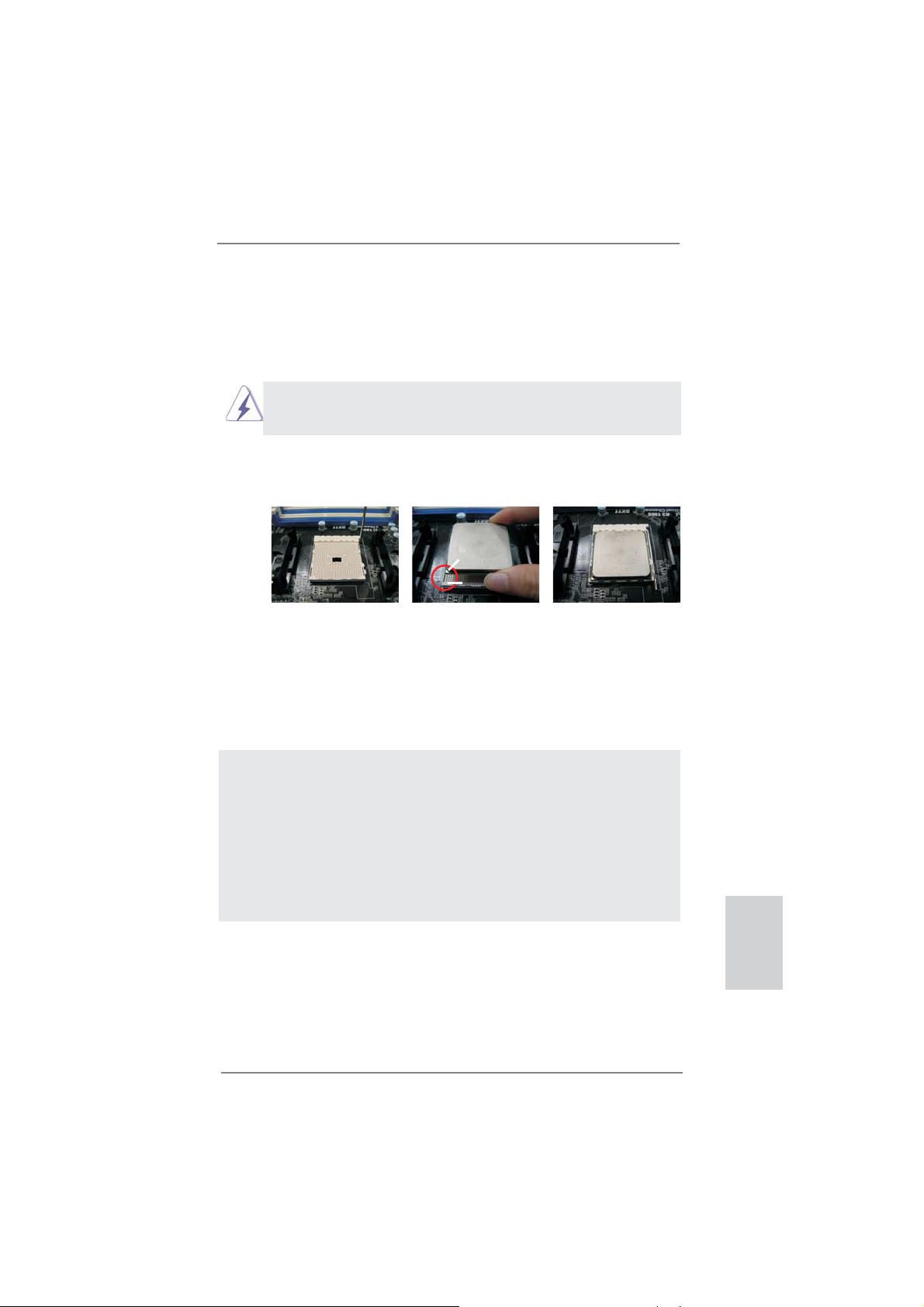
2.1 CPU Installation
Step 1. Unlock the socket by lifting the lever up to a 90
o
angle.
Step 2. Position the CPU directly above the socket such that the CPU corner with
the golden triangle matches the socket corner with a small triangle.
Step 3. Carefully insert the CPU into the socket until it fi ts in place.
The CPU fi ts only in one correct orientation. DO NOT force the CPU
into the socket to avoid bending of the pins.
Step 4. When the CPU is in place, press it fi rmly on the socket while you push
down the socket lever to secure the CPU. The lever clicks on the side tab
to indicate that it is locked.
Lever 90° Up
CPU Golden Triangle
Socket Corner Small
Triangle
STEP 1:
Lift Up The Socket Lever
STEP 2 / STEP 3:
Match The CPU Golden Triangle
To The Socket Corner Small
Triangle
STEP 4:
Push Down And Lock
The Socket Lever
2.2 Installation of CPU Fan and Heatsink
After you install the CPU into this motherboard, it is necessary to install a
larger heatsink and cooling fan to dissipate heat. You also need to spray
thermal grease between the CPU and the heatsink to improve heat dissipation. Make sure that the CPU and the heatsink are securely fastened
and in good contact with each other. Then connect the CPU fan to the
CPU FAN connector (CPU_FAN1, see Page 2, No. 4). For proper installation, please kindly refer to the instruction manuals of the CPU fan and
the heatsink.
English
ASRock FM2A85X Pro Motherboard
13
2.3 Installation of Memory Modules (DIMM)
This motherboard provides two 240-pin DDR3 (Double Data Rate 3) DIMM slots,
and supports Dual Channel Memory Technology. For dual channel configuration,
you always need to install two identical (the same brand, speed, size and chiptype) memory modules in the DDR3 DIMM slots to activate Dual Channel Memory
Technology. Otherwise, it will operate at single channel mode.
1. It is not allowed to install a DDR or DDR2 memory module into
DDR3 slot;otherwise, this motherboard and DIMM may be
damaged.
2. If you install only one memory module or two non-identical
memory modules, it is unable to activate the Dual Channel
Memory Technology.
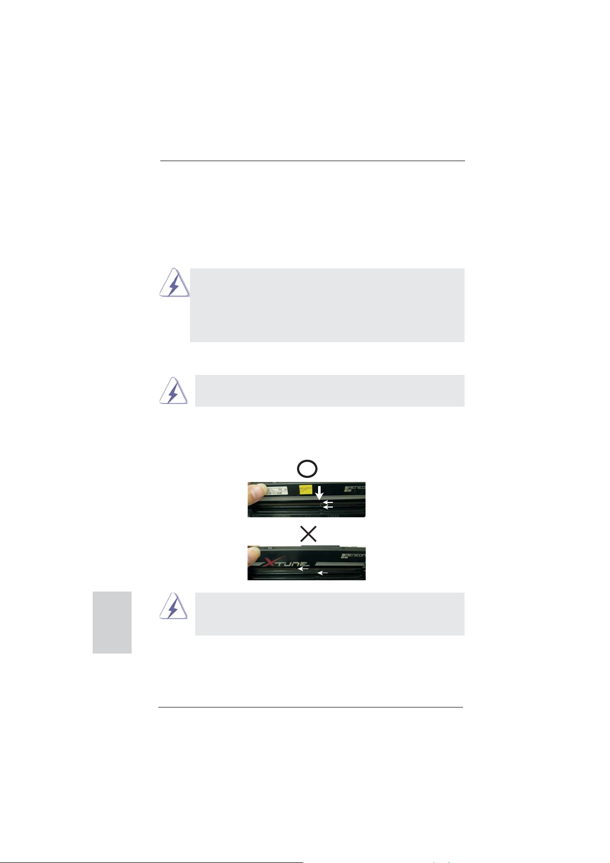
Installing a DIMM
Please make sure to disconnect power supply before adding or
removing DIMMs or the system components.
Step 1. Unlock a DIMM slot by pressing the retaining clips outward.
Step 2. Align a DIMM on the slot such that the notch on the DIMM matches the
break on the slot.
English
notch
break
notch
break
The DIMM only fi ts in one correct orientation. It will cause permanent
damage to the motherboard and the DIMM if you force the DIMM into
the slot at incorrect orientation.
Step 3. Firmly insert the DIMM into the slot until the retaining clips at both ends
fully snap back in place and the DIMM is properly seated.
14
ASRock FM2A85X Pro Motherboard
2.4 Expansion Slots (PCI and PCI Express Slots)
There are 2 PCI slots and 5 PCI Express slots on this motherboard.
PCI Slots: PCI slots are used to install expansion cards that have the 32-bit PCI
interface.
PCIE Slots:
PCIE1 / PCIE3 / PCIE4 (PCIE x1 slot) is used for PCI Express cards
with x1 lane width cards, such as Gigabit LAN card and SATA3 card.
PCIE2 (PCIE x16 slot) is used for PCI Express x16 lane width graphics
cards, or used to install PCI Express graphics cards to support CrossFi-
TM
reX
function.
PCIE5 (PCIE x16 slot) is used for PCI Express x4 lane width cards,
or used to install PCI Express graphics cards to support CrossFireX
function.
1. In single VGA card mode, it is recommended to install a PCI Express x16 graphics card on PCIE2 slot.
2. In CrossFireXTM mode, please install PCI Express x16 graphics
cards on PCIE2 and PCIE5 slots.
TM
Installing an expansion card
Step 1. Before installing the expansion card, please make sure that the power
supply is switched off or the power cord is unplugged. Please read the
documentation of the expansion card and make necessary hardware
settings for the card before you start the installation.
Step 2. Remove the system unit cover (if your motherboard is already installed
in a chassis).
Step 3. Remove the bracket facing the slot that you intend to use. Keep the
screws for later use.
Step 4. Align the card connector with the slot and press fi rmly until the card is
completely seated on the slot.
Step 5. Fasten the card to the chassis with screws.
Step 6. Replace the system cover.
ASRock FM2A85X Pro Motherboard
English
15
2.5 CrossFireXTM and Quad CrossFireXTM Operation Guide
This motherboard supports CrossFireXTM and Quad CrossFireXTM feature.
CrossFireXTM technology offers the most advantageous means available of
combining multiple high performance Graphics Processing Units (GPU) in a single
PC. Combining a range of different operating modes with intelligent software design
and an innovative interconnect mechanism, CrossFireX
TM
enables the highest
possible level of performance and image quality in any 3D application. Please check
AMD website for AMD CrossFireXTM driver updates.
1. If a customer incorrectly configures their system they will not see the
performance benefi ts of CrossFireXTM. All three CrossFireXTM components, a
CrossFireXTM Ready graphics card, a CrossFireXTM Ready motherboard and a
CrossFireXTM Edition co-processor graphics card, must be installed correctly
to benefi t from the CrossFireXTM multi-GPU platform.
2. If you pair a 12-pipe CrossFireX
will operate as 12-pipe cards while in CrossFireXTM mode.
TM
Edition card with a 16-pipe card, both cards
2.5.1 Graphics Card Setup
Different CrossFireXTM cards may require different methods to enable CrossFi-
reXTM feature. For other CrossFireXTM cards that AMD has released or will release
in the future, please refer to AMD graphics card manuals for detailed installation
guide.
English
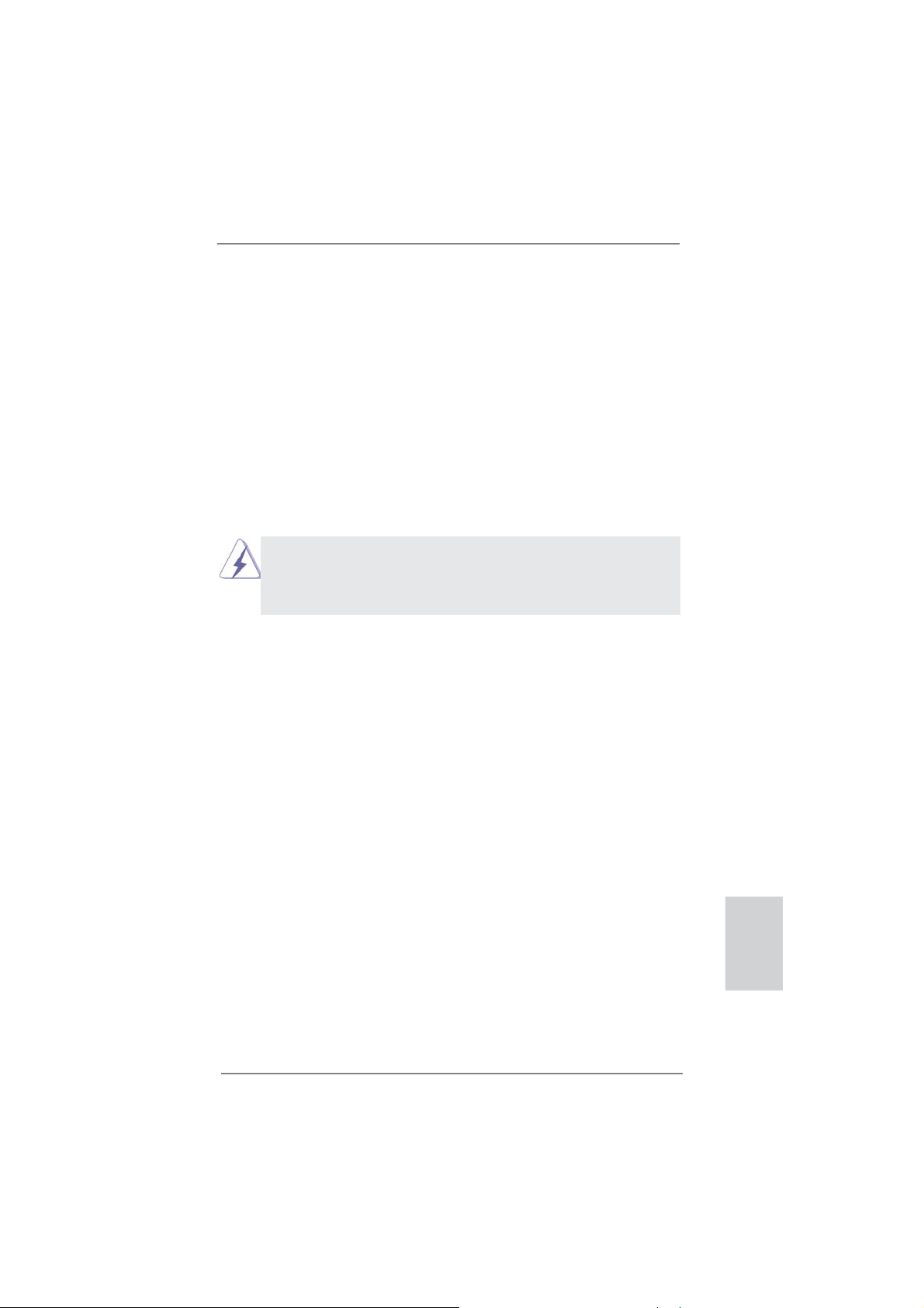
Step 1. Insert one Radeon graphics card into PCIE2 slot and the other Radeon
graphics card to PCIE5 slot. Make sure that the cards are properly seated
on the slots.
16
ASRock FM2A85X Pro Motherboard
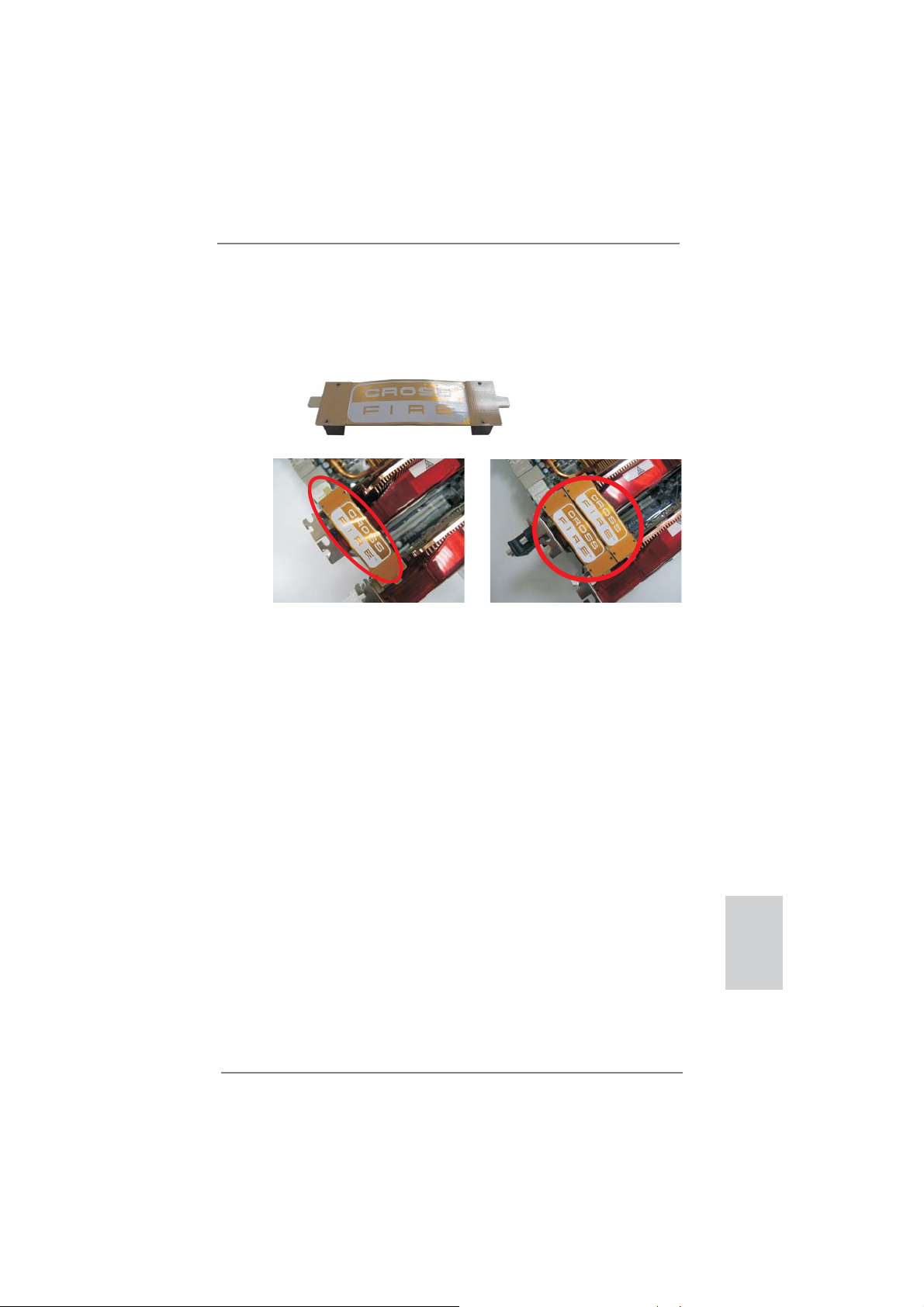
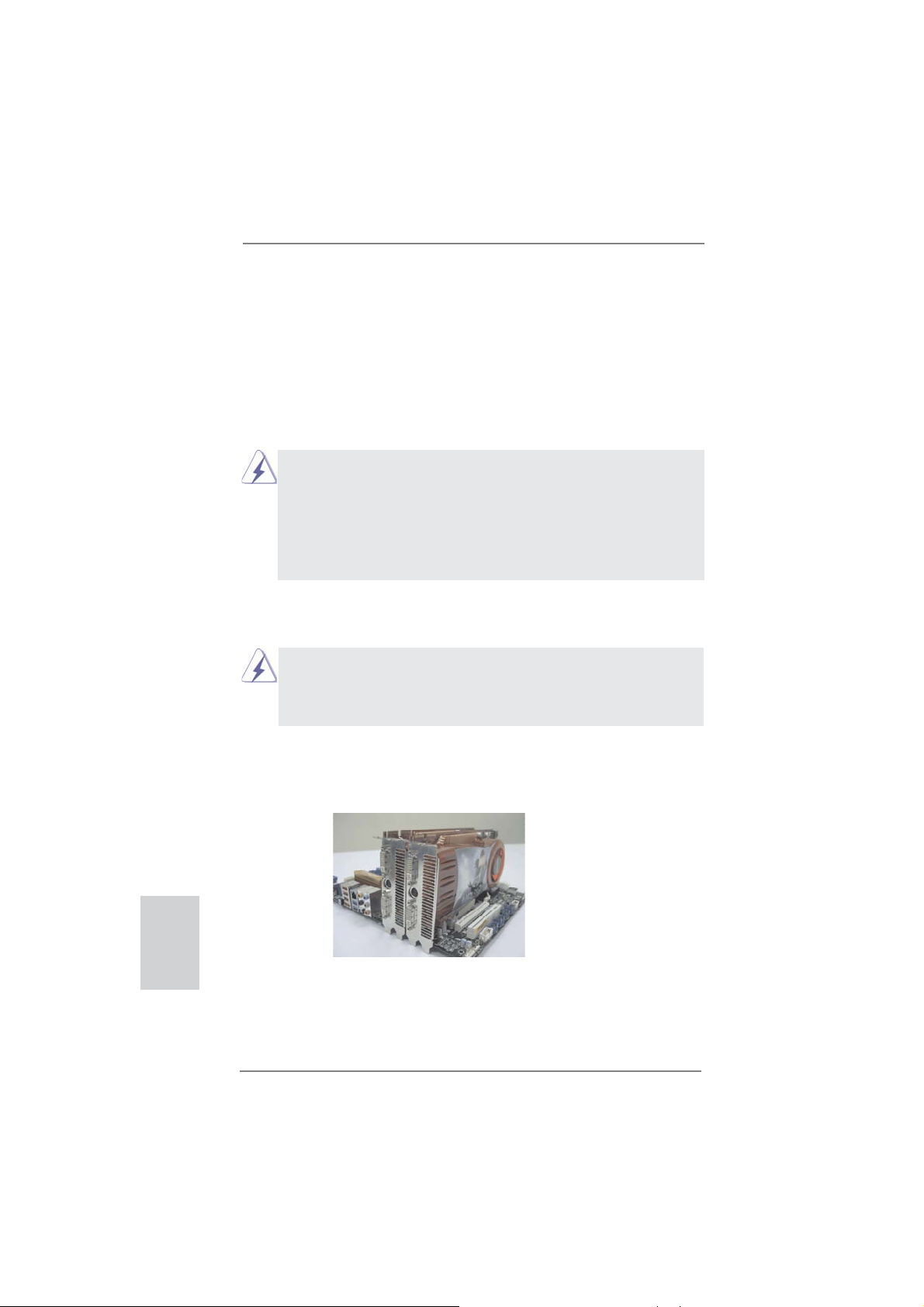
Step 2. Connect two Radeon graphics cards by installing CrossFire Bridge on
CrossFire Bridge Interconnects on the top of Radeon graphics cards.
(CrossFire Bridge is provided with the graphics card you purchase, not
bundled with this motherboard. Please refer to your graphics card vendor
for details.)
CrossFire Bridge
or
Step 3. Connect the DVI monitor cable to the DVI connector on the Radeon graph-
ics card on PCIE2 slot. (You may use the DVI to D-Sub adapter to convert
the DVI connector to D-Sub interface, and then connect the D-Sub monitor
cable to the DVI to D-Sub adapter.)
ASRock FM2A85X Pro Motherboard
English
17
2.5.2 Driver Installation and Setup
Step 1. Power on your computer and boot into OS.
Step 2. Remove the AMD driver if you have any VGA driver installed in your sys-
tem.
The Catalyst Uninstaller is an optional download. We recommend using this
utility to uninstall any previously installed Catalyst drivers prior to installation.
Please check AMD website for AMD driver updates.
Step 3. Install the required drivers to your system.
For Windows® 8 / 7 / VistaTM OS:
Install the CATALYST Control Center. Please check AMD website for de-
tails.
Step 4. Restart your computer.
Step 5. Install the VGA card drivers to your system, and restart your computer.
Then you will fi nd “ATI Catalyst Control Center” on your Windows
ATI Catalyst Control Center
®
taskbar.
English
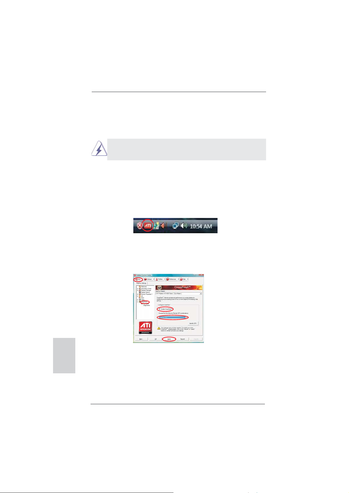
Step 6. Double-click “ATI Catalyst Control Center”. Click “View”, select “CrossFi-
TM
reX
”, and then check the item “Enable CrossFireXTM”. Select “2 GPUs”
and click “Apply” (if you install two Radeon graphics cards).
18
ASRock FM2A85X Pro Motherboard

Although you have selected the option “Enable CrossFireTM”, the Cross-
FireXTM function may not work actually. Your computer will automatically
reboot. After restarting your computer, please confi rm whether the option
“Enable CrossFireTM” in “ATI Catalyst Control Center” is selected or not;
if not, please select it again, and then you are able to enjoy the benefi t of
CrossFireX
TM
feature.
Step 7. You can freely enjoy the benefi t of CrossFireXTM or Quad CrossFireXTM
feature.
* CrossFireXTM appearing here is a registered trademark of AMD Technologies Inc., and is
used only for identifi cation or explanation and to the owners’ benefi t, without intent to infringe.
* For further information of AMD CrossFireXTM technology, please check AMD website for
updates and details.
ASRock FM2A85X Pro Motherboard
English
19
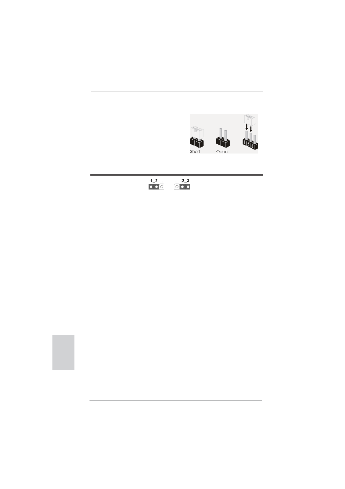
2.6 Jumpers Setup
The illustration shows how jumpers are
setup. When the jumper cap is placed on
pins, the jumper is “Short”. If no jumper cap
is placed on pins, the jumper is “Open”. The
illustration shows a 3-pin jumper whose
pin1 and pin2 are “Short” when jumper cap
is placed on these 2 pins.
Jumper Setting Description
Clear CMOS Jumper
(CLRCMOS1)
(see p.2, No. 15)
Note: CLRCMOS1 allows you to clear the data in CMOS. To clear and reset the
system parameters to default setup, please turn off the computer and unplug
the power cord from the power supply. After waiting for 15 seconds, use a
jumper cap to short pin2 and pin3 on CLRCMOS1 for 5 seconds. However,
please do not clear the CMOS right after you update the BIOS. If you need
to clear the CMOS when you just fi nish updating the BIOS, you must boot
up the system fi rst, and then shut it down before you do the clear-CMOS ac-
tion. Please be noted that the password, date, time, user default profi le, 1394
GUID and MAC address will be cleared only if the CMOS battery is removed.
Clear CMOSDefault
English
20
ASRock FM2A85X Pro Motherboard
2.7 Onboard Headers and Connectors
Onboard headers and connectors are NOT jumpers. Do NOT place
jumper caps over these headers and connectors. Placing jumper caps
over the headers and connectors will cause permanent damage of the
motherboard!
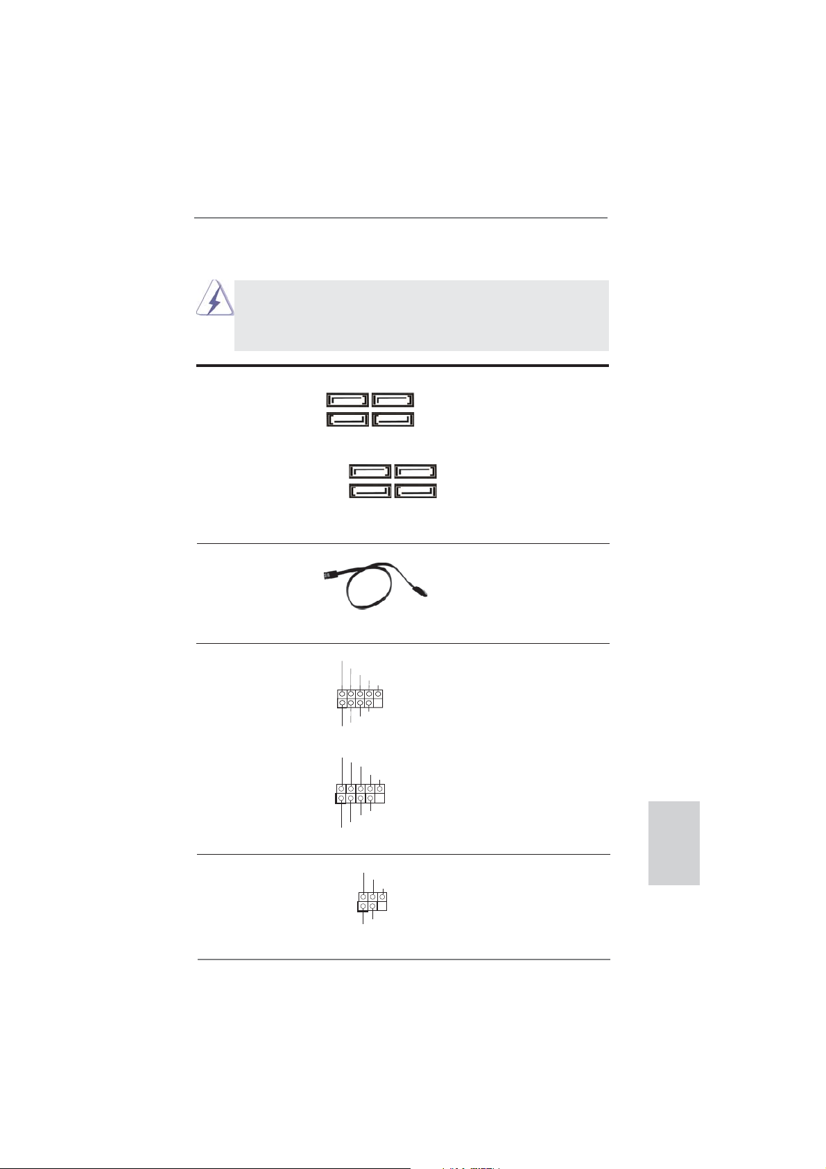
Serial ATA3 Connectors These eight Serial ATA3
(SATA_1: see p.2, No. 10)
(SATA_2: see p.2, No. 9)
(SATA_3: see p.2, No. 23)
(SATA_4: see p.2, No. 20)
(SATA_5: see p.2, No. 22)
(SATA_6: see p.2, No. 21)
(SATA_7: see p.2, No. 12)
(SATA_8: see p.2, No. 11)
SATA data cables for internal
SATA_1 SATA_2
(SATA3) connectors support
storage devices. The current
SATA_7 SATA_8
SATA3 interface allows up to
6.0 Gb/s data transfer rate.
SATA_3 SATA_4
SATA_5 SATA_6
Serial ATA (SATA) Either end of the SATA data
Data Cable cable can be connected to the
(Optional)
SATA3 hard disk or the SATA3
connector on this motherboard.
USB 2.0 Headers Besides four default USB 2.0
(9-pin USB6_7)
(see p.2 No. 25)
ports on the I/O panel, there
are two USB 2.0 headers on
this motherboard. Each USB 2.0
header can support two USB
2.0 ports.
(9-pin USB8_9)
(see p.2 No. 24)
1
1
USB_PWR
P-7
P-6
USB_PWR
USB_PWR
P-9
P-8
USB_PWR
P+7
P+6
P+9
P+8
GND
GND
GND
GND
DUMMY
DUMMY
Infrared Module Header This header supports an
(5-pin IR1)
optional wireless transmitting
(see p.2 No. 27)
and receiving infrared module.
IRTX
+5VSB
DUMMY
1
GND
IRRX
ASRock FM2A85X Pro Motherboard
English
21
Consumer Infrared Module Header This header can be used to
(4-pin CIR1)
(see p.2 No. 26)
connect the remote
controller receiver.
Front Panel Audio Header This is an interface for the front
(9-pin HD_AUDIO1)
(see p.2 No. 30)
panel audio cable that allows
convenient connection and
control of audio devices.
1
GND
PRESENCE#
MIC2_R
MIC2_L
MIC_RET
J_SENSE
OUT2_R
OUT_RET
OUT2_L
1. High Defi nition Audio supports Jack Sensing, but the panel wire on
the chassis must support HDA to function correctly. Please follow the
instruction in our manual and chassis manual to install your system.
2. If you use AC’97 audio panel, please install it to the front panel audio
header as below:
A. Connect Mic_IN (MIC) to MIC2_L.
B. Connect Audio_R (RIN) to OUT2_R and Audio_L (LIN) to OUT2_L.
C. Connect Ground (GND) to Ground (GND).
D. MIC_RET and OUT_RET are for HD audio panel only. You don’t
need to connect them for AC’97 audio panel.
E. To activate the front mic.
For Windows
®
8 / 8 64-bit / 7 / 7 64-bit / VistaTM / VistaTM 64-bit OS:
Go to the “FrontMic” Tab in the Realtek Control panel. Adjust
“Recording Volume”.
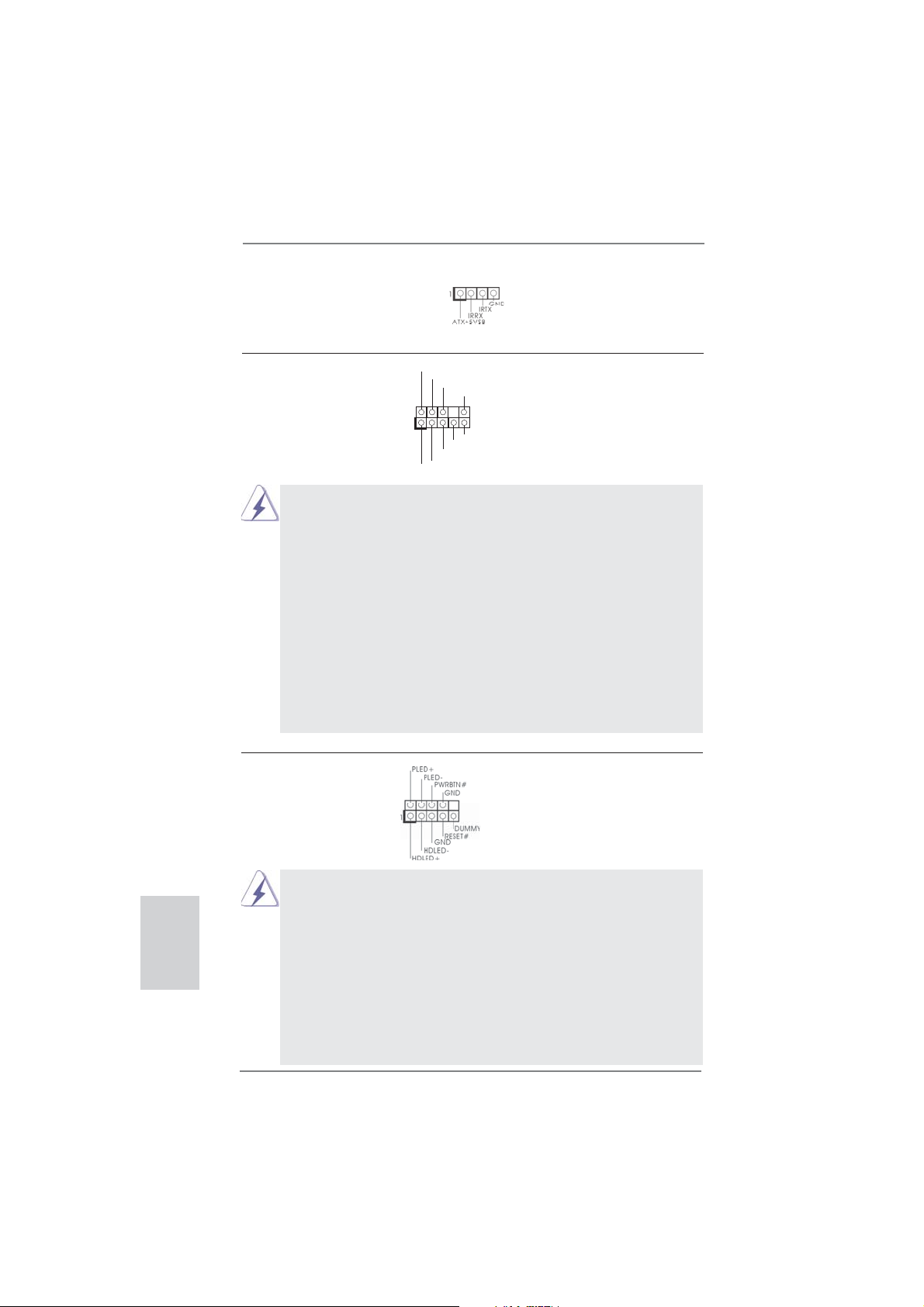
System Panel Header This header accommodates
(9-pin PANEL1)
(see p.2 No. 17)
several system front panel
functions.
English
Connect the power switch, reset switch and system status indicator
on the chassis to this header according to the pin assignments below.
Note the positive and negative pins before connecting the cables.
PWRBTN (Power Switch):
Connect to the power switch on the chassis front panel. You may confi gure the way to turn off your system using the power switch.
RESET (Reset Switch):
Connect to the reset switch on the chassis front panel. Press the reset
switch to restart the computer if the computer freezes and fails to perform a normal restart.
22
ASRock FM2A85X Pro Motherboard
PLED (System Power LED):
Connect to the power status indicator on the chassis front panel. The
LED is on when the system is operating. The LED keeps blinking
when the sys-tem is in S1 sleep state. The LED is off when the system
is in S3/S4 sleep state or powered off (S5).
HDLED (Hard Drive Activity LED):
Connect to the hard drive activity LED on the chassis front panel. The
LED is on when the hard drive is reading or writing data.
The front panel design may differ by chassis. A front panel module
mainly consists of power switch, reset switch, power LED, hard drive
activity LED, speaker and etc. When connecting your chassis front
panel module to this header, make sure the wire assignments and the
pin assign-ments are matched correctly.
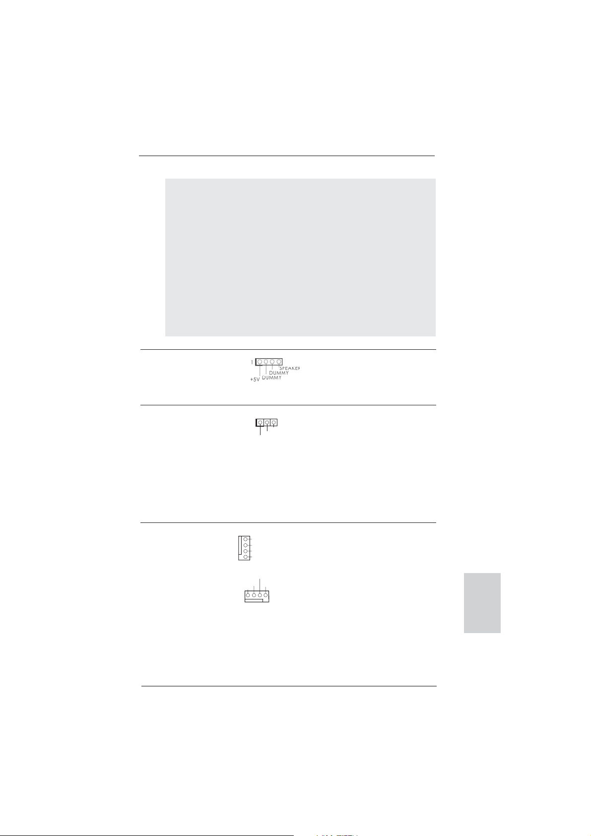
Chassis Speaker Header Please connect the chassis
(4-pin SPEAKER 1)
(see p.2 No. 16)
speaker to this header.
Power LED Header Please connect the chassis
(3-pin PLED1)
(see p.2 No. 19)
power LED to this header to
indicate system power status.
1
PLED+
PLED+
PLED-
The LED is on when the system
is operating. The LED keeps
blinking in S1 state. The LED is
off in S3/S4 state or S5 state
(power off).
Chassis Fan Connectors Please connect the fan cable
(4-pin CHA_FAN1)
(see p.2 No. 15)
to the fan connector and
match the black wire to the
ground pin.
(4-pin CHA_FAN2)
(see p.2 No. 5)
GND
+12V
CHA_FAN_SPEED
FAN_SPEED_CON TROL
CHA_FAN_SPEED
+12V
FAN_SPEED_CON TROL
GND
23
ASRock FM2A85X Pro Motherboard
English
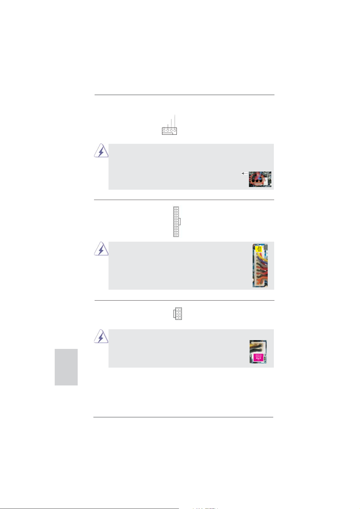
CPU Fan Connector Please connect the CPU fan
(4-pin CPU_FAN1)
(see p.2 No. 4)
cable to the connector and
match the black wire to the
ground pin.
FAN_SPEED_CONTROL
CPU_FAN_SPEED
+12V
GND
1 2 3 4
Though this motherboard provides 4-Pin CPU fan (Quiet Fan) support, the 3-Pin
CPU fan still can work successfully even without the fan speed control function.
If you plan to connect the 3-Pin CPU fan to the CPU fan connector on this
motherboard, please connect it to Pin 1-3.
Pin 1-3 Connected
3-Pin Fan Installation
English
ATX Power Connector Please connect an ATX power
(24-pin ATXPWR1)
(see p.2 No. 7)
Though this motherboard provides 24-pin ATX power connector,
it can still work if you adopt a traditional 20-pin ATX power supply.
supply to this connector.
12
24
1
13
12
To use the 20-pin ATX power supply, please plug your power
supply along with Pin 1 and Pin 13.
20-Pin ATX Power Supply Installation
ATX 12V Power Connector Please connect an ATX 12V
(8-pin ATX12V1)
(see p.2 No. 1)
power supply to this connector.
5 1
8 4
1
Though this motherboard provides 8-pin ATX 12V power connector, it can still work
if you adopt a traditional 4-pin ATX 12V power supply. To use the
5 1
4-pin ATX power supply, please plug your power supply along with
Pin 1 and Pin 5.
4-Pin ATX 12V Power Supply Installation
8 4
24
13
24
ASRock FM2A85X Pro Motherboard
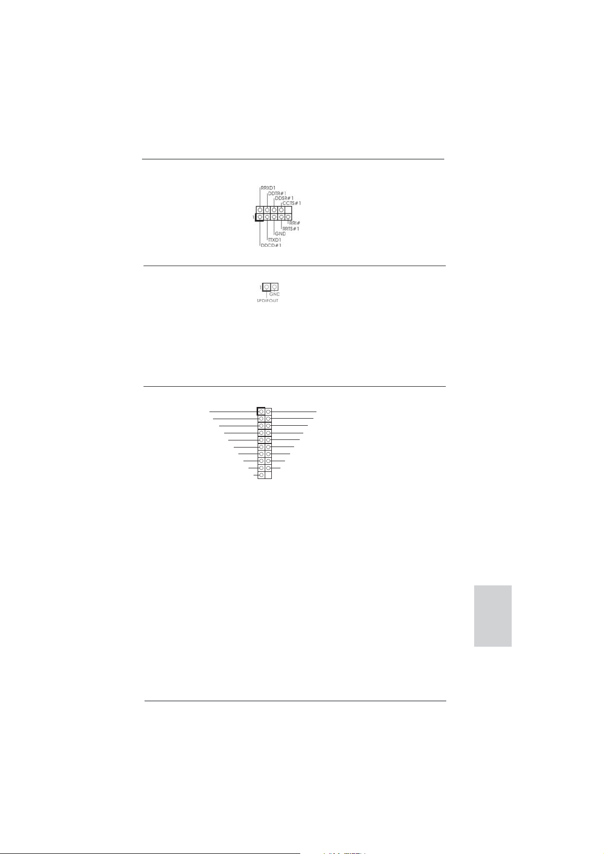
Serial port Header This COM1 header supports a
_
_
(9-pin COM1)
(see p.2 No. 28)
serial port module.
HDMI_SPDIF Header HDMI_SPDIF header, providing
(2-pin HDMI_SPDIF1)
see p.2 No. 29)
(
SPDIF audio output to HDMI
VGA card, allows the system to
connect HDMI Digital TV/
projector/LCD devices. Please
connect the HDMI_SPDIF
connector of HDMI VGA card to
this header.
USB 3.0 Header Besides two default USB 3.0
(19-pin USB3_2_3)
(see p.2 No. 8)
motherboard. This USB 3.0
header can support two USB 3.0
ports.
ports on the I/O panel, there is
ID
one USB 3.0 header on this
IntA_P_D+
GND
IntA_P_D-
IntA_P_SSTX+
IntA_P_SSTX-
1
GND
Vbus
IntA_P_SSRX +
IntA_P_SSRX-
Vbus
IntA_P_SSRX-
D+
P
IntA
GND
IntA_P_D-
GND
IntA_P_SSTX+
IntA_P_SSTX-
IntA_P_SSRX +
English
ASRock FM2A85X Pro Motherboard
25

2.8 Driver Installation Guide
To install the drivers to your system, please insert the support CD to your optical
drive fi rst. Then, the drivers compatible to your system can be auto-detected and
listed on the support CD driver page. Please follow the order from up to bottom side
to install those required drivers. Therefore, the drivers you install can work properly.
2.9 Installing Windows® 8 / 8 64-bit / 7 / 7 64-bit / VistaTM /
VistaTM 64-bit With RAID Functions
If you want to install Windows® 8 / 8 64-bit / 7 / 7 64-bit / VistaTM / VistaTM 64-bit on a
RAID disk composed of 2 or more SATA3 HDDs with RAID functions, please follow
below steps.
STEP 1: Set up UEFI.
A. Enter UEFI SETUP UTILITY Advanced screen Storage
Confi guration.
B. Set the “SATA Mode” option to [RAID].
STEP 2: Use “RAID Installation Guide” to set RAID confi guration.
Before you start to confi gure RAID function, you need to check the RAID installation
guide in the Support CD for proper confi guration. Please refer to the BIOS RAID
installation guide part of the document in the following path in the Support CD:
.. \ RAID Installation Guide
STEP 3: Install Windows
your system.
Use the option “Easy RAID Installer“ in UEFI setup utility to copy the RAID drivers
to your USB fl ash disk. Insert the Windows
boot your system, and follow the instruction to install OS on your system. When you
see “Where do you want to install Windows?” page, please insert your USB fl ash
disk to your system, and click the “Load Driver” button to load the RAID drivers.
After that, you can continue the OS installation.
®
8 / 8 64-bit / 7 / 7 64-bit / VistaTM / VistaTM 64-bit OS on
®
OS optical disk into the optical drive to
English
26
ASRock FM2A85X Pro Motherboard

2.10 Installing Windows® 8 / 8 64-bit / 7 / 7 64-bit / VistaTM /
Vista
If you want to install Windows® 8 / 8 64-bit / 7 / 7 64-bit / VistaTM / VistaTM 64-bit on
your SATA3 HDDs without RAID functions, please follow below steps.
Using SATA3 HDDs without NCQ and Hot Plug functions (IDE mode)
STEP 1: Set up UEFI.
A. Enter UEFI SETUP UTILITY Advanced screen Storage
Confi guration.
B. Set the “SATA Mode” option to [IDE].
STEP 2: Install Windows
Using SATA3 HDDs with NCQ and Hot Plug functions (AHCI mode)
STEP 1: Set up UEFI.
A. Enter UEFI SETUP UTILITY Advanced screen Storage
Confi guration.
B. Set the “SATA Mode” option to [AHCI].
STEP 2: Install Windows
TM
64-bit Without RAID Functions
®
8 / 8 64-bit / 7 / 7 64-bit / VistaTM / VistaTM 64-bit OS on
your system.
®
8 / 8 64-bit / 7 / 7 64-bit / VistaTM / VistaTM 64-bit OS on
your system.
ASRock FM2A85X Pro Motherboard
English
27

3. BIOS Information
The Flash Memory on the motherboard stores BIOS Setup Utility. When you start up
the computer, please press <F2> or <Del> during the Power-On-Self-Test (POST)
to enter BIOS Setup utility; otherwise, POST continues with its test routines. If you
wish to enter BIOS Setup after POST, please restart the system by pressing <Ctl>
+ <Alt> + <Delete>, or pressing the reset button on the system chassis. The BIOS
Setup program is designed to be user-friendly. It is a menu-driven program, which
allows you to scroll through its various sub-menus and to select among the predetermined choices. For the detailed information about BIOS Setup, please refer to the
User Manual (PDF fi le) contained in the Support CD.
4. Software Support CD information
®
This motherboard supports various Microsoft
8 64-bit / 7 / 7 64-bit / VistaTM / Vista
motherboard contains necessary drivers and useful utilities that will enhance motherboard features. To begin using the Support CD, insert the CD into your CD-ROM
drive. It will display the Main Menu automatically if “AUTORUN” is enabled in your
computer. If the Main Menu does not appear automatically, locate and double-click
on the fi le “ASSETUP.EXE” from the BIN folder in the Support CD to display the
menus.
TM
Windows® operating systems: 8 /
64-bit. The Support CD that came with the
English
28
ASRock FM2A85X Pro Motherboard
1. Einführung
Wir danken Ihnen für den Kauf des ASRock FM2A85X Pro Motherboard, ein zuver-
lässiges Produkt, welches unter den ständigen, strengen Qualitätskontrollen von
ASRock gefertigt wurde. Es bietet Ihnen exzellente Leistung und robustes Design,
gemäß der Verpflichtung von ASRock zu Qualität und Halbarkeit. Diese Schnellinstallationsanleitung führt in das Motherboard und die schrittweise Installation
ein. Details über das Motherboard fi nden Sie in der Bedienungsanleitung auf der
Support-CD.
Da sich Motherboard-Spezifi kationen und BIOS-Software verändern
können, kann der Inhalt dieses Handbuches ebenfalls jederzeit geändert
werden. Für den Fall, dass sich Änderungen an diesem Handbuch
ergeben, wird eine neue Version auf der ASRock-Website, ohne weitere
Ankündigung, verfügbar sein. Die neuesten Grafi kkarten und unterstützten
CPUs sind auch auf der ASRock-Website aufgelistet.
ASRock-Website: http://www.asrock.com
Wenn Sie technische Unterstützung zu Ihrem Motherboard oder spezifi sche
Informationen zu Ihrem Modell benötigen, besuchen Sie bitte unsere
Webseite:
www.asrock.com/support/index.asp
1.1 Kartoninhalt
ASRock FM2A85X Pro Motherboard (ATX-Formfaktor)
ASRock FM2A85X Pro Schnellinstallationsanleitung
ASRock FM2A85X Pro Support-CD
Zwei Serial ATA (SATA) -Datenkabel (optional)
Ein I/O Shield
ASRock erinnert...
Zur besseren Leistung unter Windows® 8 / 8 64 Bit / 7 / 7 64 Bit / Vista
TM
Vista
64 Bit empfehlen wir, die Speicherkonfi guration im BIOS auf den
AHCI-Modus einzustellen. Hinweise zu den BIOS-Einstellungen fi nden
Sie in der Bedienungsanleitung auf der mitgelieferten CD.
TM
ASRock FM2A85X Pro Motherboard
/
Deutsch
29
Deutsch
1.2 Spezifi kationen
Plattform - ATX-Formfaktor
- Alle Feste Kondensatordesign
CPU - Unterstützt Sockel-FM2-100-W-Prozessoren
- 4 + 1-Stromphasendesign
- Unterstützt Cool ‘n’ Quiet
- UMI-Link-GEN2
Chipsatz - AMD A85X (Hudson-D4)
Speicher - Unterstützung von Dual-Kanal-Speichertechnologie
- 2 x Steckplätze für DDR3
- Unterstützt DDR3 1866/1600/1333/1066 non-ECC,
ungepufferter Speicher
- Max. Kapazität des Systemspeichers: 32GB
- Unterstützt Intel
®
- Unterstützt AMD Memory Profi le (AMP)
Erweiterungs- - 2 x PCI-Express-2.0-x16-Steckplätze
steckplätze (PCIE2: x16-Modus; PCIE5: x4-Modus)
- 3 x PCI Express 2.0 x1-Steckplätze
- 2 x PCI -Steckplätze
- Unterstützt AMD Quad CrossFireX
duale Grafi kkarten
Onboard-VGA - AMD Radeon HD 7000-Grafi k
- DirectX 11, Pixel Shader 5.0
- Maximal gemeinsam genutzter Speicher 2GB
- Doppel-VGA Ausgabe: unterstützt DVI und D-Sub Ports
durch unabhängige Bildschirmanzeige Kontrolleure
- Unterstützt Dual-link DVI mit einer maximalen Aufl ösung von
2560 x 1600 bei 75 Hz
- Unterstützt D-Sub mit einer maximalen Aufl ösung von
1920 x 1600 bei 60 Hz
- Unterstützt AMD Steady Video
Videonachbearbeitung für automatische Reduzierung von
Bildschwankungen bei Heim-/Online-Videos
- Unterstützt HDCP-Funktion mit DVI-Port
- Unterstutzt 1080p Blu-ray (BD) / HD-DVD-Wiedergabe
mit DVI-Port
Audio - 5.1
CH HD Audio (Realtek ALC662 Audio Codec)
LAN - PCIE x1 Gigabit LAN 10/100/1000 Mb/s
- Realtek RTL8111E
- Unterstützt Wake-On-LAN
TM
-Technologie von AMD
Extreme Memory Profi le (XMP)1.3/1.2
TM
, CrossFireXTM und
TM
: Neuartige Funktion der
30
ASRock FM2A85X Pro Motherboard
 Loading...