

Page 1

Multi Book G22
User Manual
Page 2

Contents
Table of Contents
Table of Contents
1. Introduction
About This User’s Manual ������������������������������������������������������������������������������������������6
Notes For This Manual ������������������������������������������������������������������������������������������� 6
2. Knowing the Parts
Top Side��������������������������������������������������������������������������������������������������������������������10
Front Side ����������������������������������������������������������������������������������������������������������������� 11
Rear Side������������������������������������������������������������������������������������������������������������������ 11
Left Side �������������������������������������������������������������������������������������������������������������������12
Right Side �����������������������������������������������������������������������������������������������������������������12
3. Getting Started
Power System ����������������������������������������������������������������������������������������������������������14
Using AC Power ��������������������������������������������������������������������������������������������������� 14
Using Battery Power ��������������������������������������������������������������������������������������������15
Powering ON the Notebook PC ���������������������������������������������������������������������������16
Checking Battery Power �������������������������������������������������������������������������������������� 17
Charging the Battery Pack ����������������������������������������������������������������������������������� 17
Power Options ����������������������������������������������������������������������������������������������������� 18
Power Management Modes ��������������������������������������������������������������������������������� 19
Sleep and Hibernate �������������������������������������������������������������������������������������������� 19
Thermal Power Control ���������������������������������������������������������������������������������������� 19
Special Keyboard Functions �������������������������������������������������������������������������������������20
Colored Hot Keys ������������������������������������������������������������������������������������������������� 20
Microsoft Windows Keys �������������������������������������������������������������������������������������� 22
Keyboard as a Numeric Keypad ������������������������������������������������������������������������� 22
Keyboard as Cursors ������������������������������������������������������������������������������������������� 22
Status Indicators �������������������������������������������������������������������������������������������������� 23
2
Page 3

Contents
Table of Contents (Cont.)
4. Using the Notebook PC
Pointing Device��������������������������������������������������������������������������������������������������������� 26
Using the Touchpad ��������������������������������������������������������������������������������������������� 26
Multi-touch gesture usage ����������������������������������������������������������������������������������27
Caring for the Touchpad ���������������������������������������������������������������������������������������28
Automatic Touchpad Disabling �����������������������������������������������������������������������������28
Flash Memory Card Reader ��������������������������������������������������������������������������������29
Optical Drive �������������������������������������������������������������������������������������������������������� 30
Hard Disk Drive ���������������������������������������������������������������������������������������������������� 32
Memory (RAM)�����������������������������������������������������������������������������������������������������33
Connections�������������������������������������������������������������������������������������������������������������� 34
Network Connection ��������������������������������������������������������������������������������������������34
Modem Connection ���������������������������������������������������������������������������������������������� 35
Wireless LAN Connection (on selected models) ������������������������������������������������� 36
Windows Wireless Network Connection �������������������������������������������������������������� 37
Bluetooth Wireless Connection (on selected models) ����������������������������������������� 38
3
Page 4

Contents
4
Page 5

1. Introduction
About This User’s Manual
Notes For This Manual
Safety Precautions
NOTE: Photos and icons in this manual are used for artistic purposes only and do not
show what is actually used in the product itself.
5
Page 6
1 Introducing the Notebook PC
About This User’s Manual
You are reading the Notebook PC User’s Manual. This User’s Manual provides information on the various components in the Notebook PC and how to use them. The following
are major sections of this User’s Manuals:
1. Introducing the Notebook PC
Introduces you to the Notebook PC and this User’s Manual.
2. Knowing the Parts
Gives you information on the Notebook PC’s components.
3. Getting Started
Gives you information on getting started with the Notebook PC.
4. Using the Notebook PC
Gives you information on using the Notebook PC’s components.
5. Appendix
Introduces you to optional accessories and gives additional information.
Notes For This Manual
A few notes and warnings in bold are used throughout this guide that you should be aware of in order
to complete certain tasks safely and completely. These notes have different degrees of importance as
described below:
NOTE: Tips and information for special situations.
TIP: Tips and useful information for completing tasks.
IMPORTANT! Vital information that must be followed to prevent damage to data, components, or persons.
WARNING! Important information that must be followed for safe operation.
< >
Text enclosed in < > or [ ] represents a key on the keyboard; do not actually type the
< > or [ ] and the enclosed letters.
[ ]
6
Page 7
Introducing the Notebook PC 1
Safety Precautions
The following safety precautions will increase the life of the Notebook PC. Follow all precautions and
instructions. Except as described in this manual, refer all servicing to qualied personnel. Do not use
damaged power cords, accessories, or other peripherals. Do not use strong solvents such as thinners,
benzene, or other chemicals on or near the surface.
IMPORTANT! Disconnect the AC power and remove the battery pack(s) before cleaning. Wipe the Notebook PC using a clean cellulose sponge or chamois cloth dampened
with a solution of nonabrasive detergent and a few drops of warm water and remove
any extra moisture with a dry cloth.
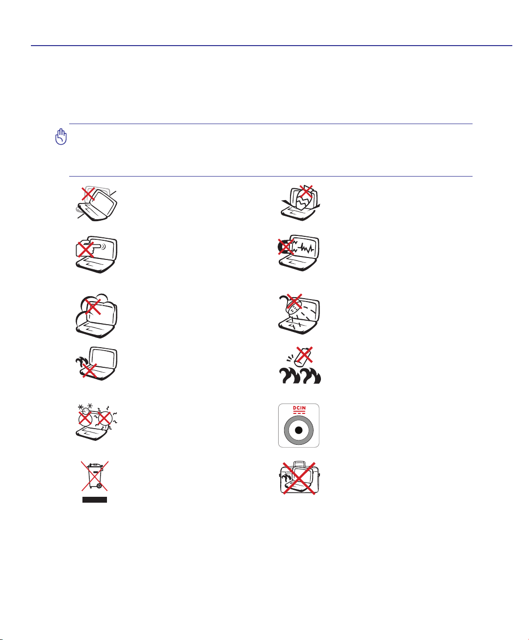
DO NOT place on uneven or unstable
work surfaces. Seek servicing if the
casing has been damaged.
DO NOT press or touch the display
panel. Do not place together with
small items that may scratch or enter
the Notebook PC.
DO NOT expose to dirty or dusty environments. DO NOT operate during
a gas leak.
DO NOT leave the Notebook PC on
your lap or any part of the body in
order to prevent discomfort or injury
from heat exposure.
SAFE TEMP: This Notebook PC
should only be used in environments
with ambient temperatures between
5°C (41°F) and 35°C (95°F)
DO NOT throw the Notebook PC
in munici pal waste. Check local
regulations for disposal of electronic
products.
DO NOT place or drop objects on top
and do not shove any foreign objects
into the Notebook PC.
DO NOT expose to strong magnetic
or electrical elds.
DO NOT expose to or use near liquids,
rain, or moisture. DO NOT use the
modem during an electrical storm.
Battery safety warning:
DO NOT throw the battery in re.
DO NOT short circuit the contacts.
DO NOT disassemble the battery.
INPUT RATING: Refer to the rating
label on the bottom of the Notebook
PC and be sure that your power adapter
complies with the rating.
DO NOT carry or cover a Notebook
PC that is powered ON with any materials that will reduce air circulation
such as a carrying bag.
7
Page 8

1 Introducing the Notebook PC
8
Page 9

2. Knowing the Parts
Basic sides of the Notebook PC
NOTE: Photos and icons in this manual are used for artistic purposes only and do not
show what is actually used in the product itself.
9
Page 10
2 Knowing the Parts
31 2
4
5
6
7
8
2
3
4
1
5
6
7
8
Top Side
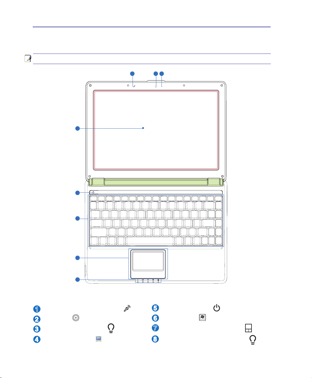
Refer to the diagram below to identify the components on this side of the Notebook PC.
NOTE: The keyboard will be different for each territory.
Microphone (Built-in)
Camera
Camera Indicator
Display Panel
10
Power Switch
Keyboard
Touchpad and Buttons
Status Indicators (front)
Page 11
Knowing the Parts 2
2 3 41
1
2
3
4
7
5
6
8
6
5
7
8
Front Side
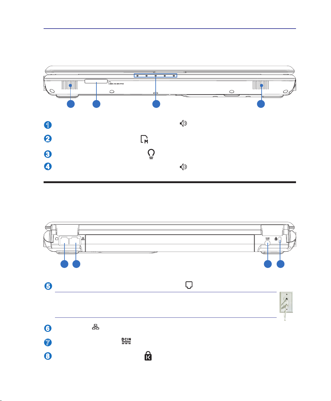
Refer to the diagram below to identify the components on this side of the Notebook PC.
Audio Speakers (Left and Right)
Flash Memory Reader
Status Indicators (front)
Audio Speakers (Left and Right)
Rear Side
Refer to the diagram below to identify the components on this side of the Notebook PC.
Modem Port (on selected models)
IMPORTANT! The built-in modem does not support the voltage used in
digital phone systems. Do not connect the modem port to a digital phone
system or else damage will occur to the Notebook PC.
LAN Port
Power (DC) Input
Kensington® Lock Port
11
Page 12
2 Knowing the Parts
HDMI
13
14
15
13
15
11
9
10
12
10
11
12
9
14
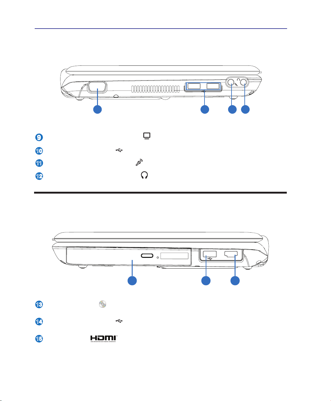
Left Side
Refer to the diagram below to identify the components on this side of the Notebook PC.
Display (Monitor) Output
USB Port (2.0/1.1)
Microphone Input Jack
Headphone Output Jack
Right Side
Refer to the diagram below to identify the components on this side of the Notebook PC.
Optical Drive
USB Port (2.0/1.1)
HDMI Port
12
Page 13

3. Getting Started
Using AC Power
Using Battery Power
Powering ON the Notebook PC
Checking Battery Power
Powering Options
Power Management Modes
Special Keyboard Functions
Switches and Status Indicators
NOTE: Photos and icons in this manual are used for artistic purposes only and do not
show what is actually used in the product itself.
13
Page 14
3 Getting Started
Power System
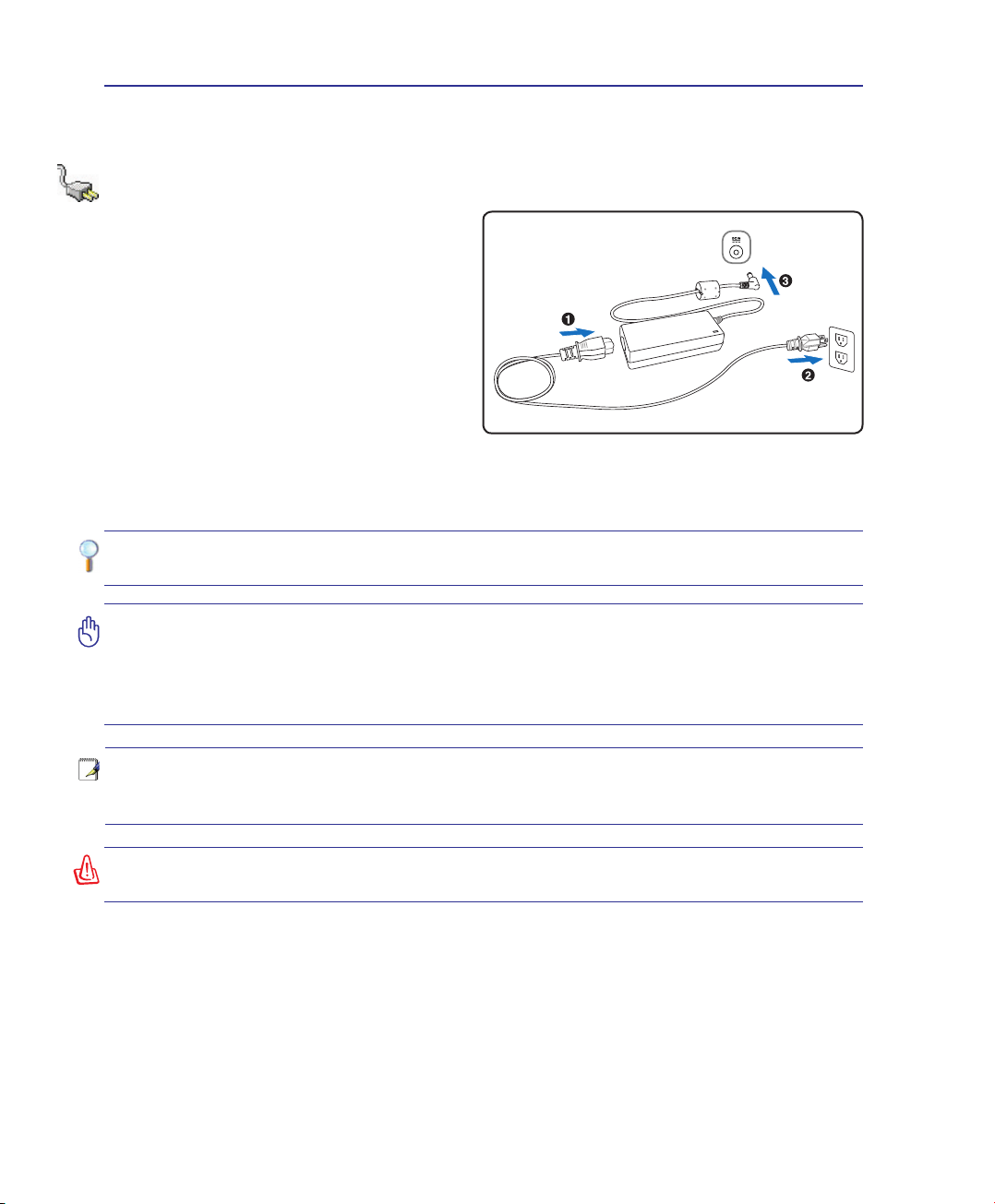
Using AC Power
The Notebook PC power is comprised of two parts,
the power adapter and the battery power system.
The power adapter converts AC power from a wall
outlet to the DC power required by the Notebook
PC. Your Notebook PC comes with a universal
AC-DC adapter. That means that you may connect
the power cord to any 100V-120V as well as 220V240V outlets without setting switches or using
power converters. Different countries may require
that an adapter be used to connect the provided
US-standard AC power cord to a different standard.
Most hotels will provide universal outlets to support different power cords as well as voltages. It is always best to ask an experienced traveler about AC
outlet voltages when bringing power adapters to another country.
TIP: You can buy travel kits for the Notebook PC that includes power and modem
adapters for almost every country.
IMPORTANT! Damage may occur if you use a different adapter to power the Notebook
PC or use the Notebook PC’s adapter to power other electrical devices. If there is
smoke, burning scent, or extreme heat coming from the AC-DC adapter, seek servicing. Seek servicing if you suspect a faulty AC-DC adapter. You may damage both your
battery pack(s) and the Notebook PC with a faulty AC-DC adapter.
NOTE: This Notebook PC may come with either a two or three-prong plug depending
on territory. If a three-prong plug is provided, you must use a grounded AC outlet or
use a properly grounded adapter to ensure safe operation of the Notebook PC.
WARNING! THE POWER ADAPTER MAY BECOME WARM TO HOT WHEN IN USE. BE
SURE NOT TO COVER THE ADAPTER AND KEEP IT AWAY FROM YOUR BODY.
14
Page 15
Getting Started 3
L
L
L
L
3
1
2
L
L
L
L
1
2
3
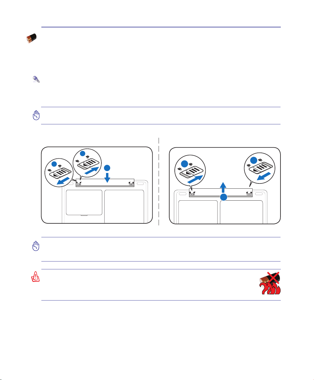
Using Battery Power
The Notebook PC is designed to work with a removable battery pack. The battery pack consists of a set
of battery cells housed together. A fully charged pack will provide several hours of battery life, which
can be further extended by using power management features through the BIOS setup. Additional battery
packs are optional and can be purchased separately through a Notebook PC retailer.
Installing and Removing the Battery Pack
Your Notebook PC may or may not have its battery pack installed. If your Notebook PC does not have
its battery pack installed, use the following procedures to install the battery pack.
IMPORTANT! Never attempt to remove the battery pack while the Notebook PC is
turned ON, as this may result in the loss of working data.
To install the battery pack:
To remove the battery pack:
IMPORTANT! Only use battery packs and power adapters supplied with this Notebook
PC or specically approved by the manufacturer or retailer for use with this model or
else damage may occur to the Notebook PC.
WARNING! For safety reasons, DO NOT throw the battery in re, DO NOT
short circuit the contacts, and DO NOT disassemble the battery. If there is
any abnormal operation or damage to the battery pack caused by impact,
turn OFF the Notebook PC and contact an authorized service center.
15
Page 16
3 Getting Started
Powering ON the Notebook PC
The Notebook PC’s power-ON message appears on the screen when you turn it ON. If necessary, you
may adjust the brightness by using the hot keys. If you need to run the BIOS Setup to set or modify the
system conguration, press [F2] upon bootup to enter the BIOS Setup. If you press [Tab] during the
splash screen, standard boot information such as the BIOS version can be seen. Press [ESC] and you will
be presented with a boot menu with selections to boot from your available drives.
NOTE: Before bootup, the display panel ashes when the power is turned ON. This is
part of the Notebook PC’s test routine and is not a problem with the display.
IMPORTANT! To protect the hard disk drive, always wait at least 5 seconds after turning OFF your Notebook PC before turning it back ON.
WARNING! DO NOT carry or cover a Notebook PC that is powered ON with any materials that will reduce air circulation such as a carrying bag.
IMPORTANT! If warnings are still given during bootup after running a software disk
checking utility, you should take your Notebook PC in for servicing. Continued use
may result in data loss.
16
Page 17
Getting Started 3
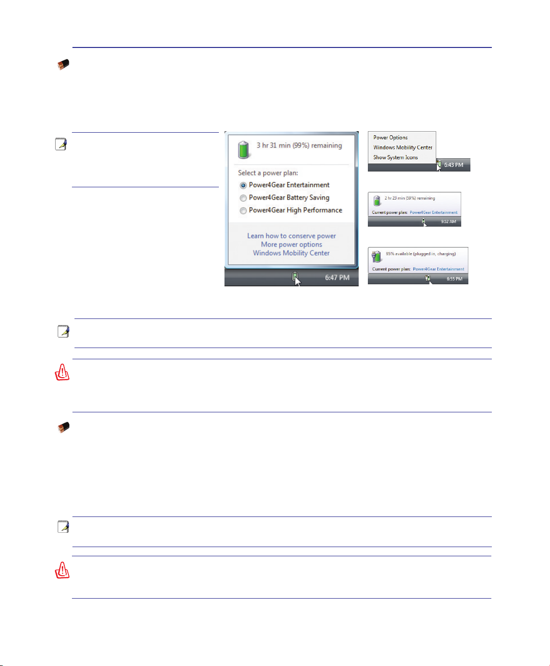
Checking Battery Power
The battery system implements the Smart Battery standard under the Windows environment, which
allows the battery to accurately report the amount of charge left in the battery. A fully-charged battery
pack provides the Notebook PC a few hours of working power. But the actual gure varies depending
on how you use the power saving features, your general work habits, the CPU, system memory size,
and the size of the display panel.
Note: Screen captures shown
here are examples only and
may not reect what you see
in your system.
Right-click the battery icon
Cursor over the battery icon without
power adapter�
Left-click the battery icon
NOTE: You will be warned when battery power is low. If you continue to ignore the low battery
warnings, the Notebook PC eventually enters suspend mode (Windows default uses STR).
WARNING! Suspend-to-RAM (STR) does not last long when the battery power is depleted.
Suspend-to-Disk (STD) is not the same as power OFF. STD requires a small amount of
power and will fail if no power is available due to complete battery depletion or no power
supply (e.g. removing both the power adapter and battery pack).
Cursor over the battery icon with
power adapter�
Charging the Battery Pack
Before you use your Notebook PC on the road, you will have to charge the battery pack. The battery pack
begins to charge as soon as the Notebook PC is connected to external power using the power adapter.
Fully charge the battery pack before using it for the rst time. A new battery pack must completely charge
before the Notebook PC is disconnected from external power. It takes a few hours to fully charge the battery when the Notebook PC is turned OFF and may take twice the time when the Notebook PC is turned
ON. The battery status indicator on the Notebook PC turns OFF when the battery pack is charged.
NOTE: The battery stops charging if the temperature is too high or the battery voltage
is too high.
WARNING! Do not leave the battery pack discharged. The battery pack will discharge
over time. If not using a battery pack, it must continued to be charged every three
months to extend recovery capacity or else it may fail to charge in the future.
17
Page 18
3 Getting Started
Power Options
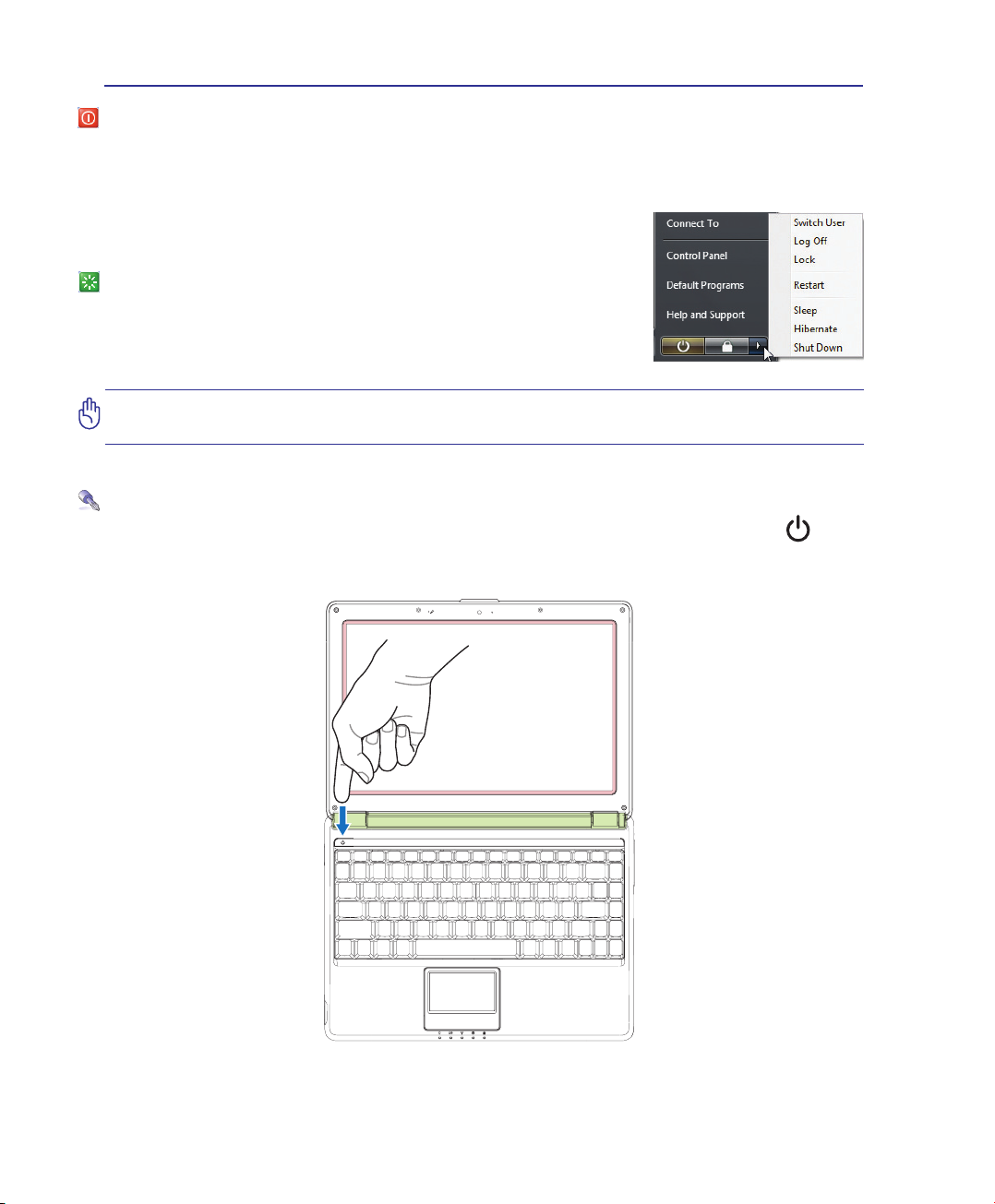
The power switch turns ON and OFF the Notebook PC or putting the Notebook PC into sleep or hibernation modes. Actual behavior of the power switch can be customized in Windows Control Panel “Power
Options.”
For other options, such as “Switch User, Restart, Sleep, or Shut Down,”
click the arrowhead next to the lock icon.
Restarting or Rebooting
After making changes to your operating system, you may be prompted to
restart the system. Some installation processes will provide a dialog box
to allow restart. To restart the system manually, choose Restart.
IMPORTANT! To protect the hard drive, wait at least 5 seconds after turning OFF your
Notebook PC before turning it back ON.
Emergency Shutdown
In case your operating system cannot properly turn OFF or restart, hold the power button over 4
seconds to shutdown your Notebook PC.
18
Page 19
Getting Started 3
Power Management Modes
The Notebook PC has a number of automatic or adjustable power saving features that you can use to
maximize battery life and lower Total Cost of Ownership (TCO). You can control some of these features
through the Power menu in the BIOS Setup. ACPI power management settings are made through the
operating system. The power management features are designed to save as much electricity as possible
by putting components into a low power consumption mode as often as possible but also allow full
operation on demand.
Sleep and Hibernate
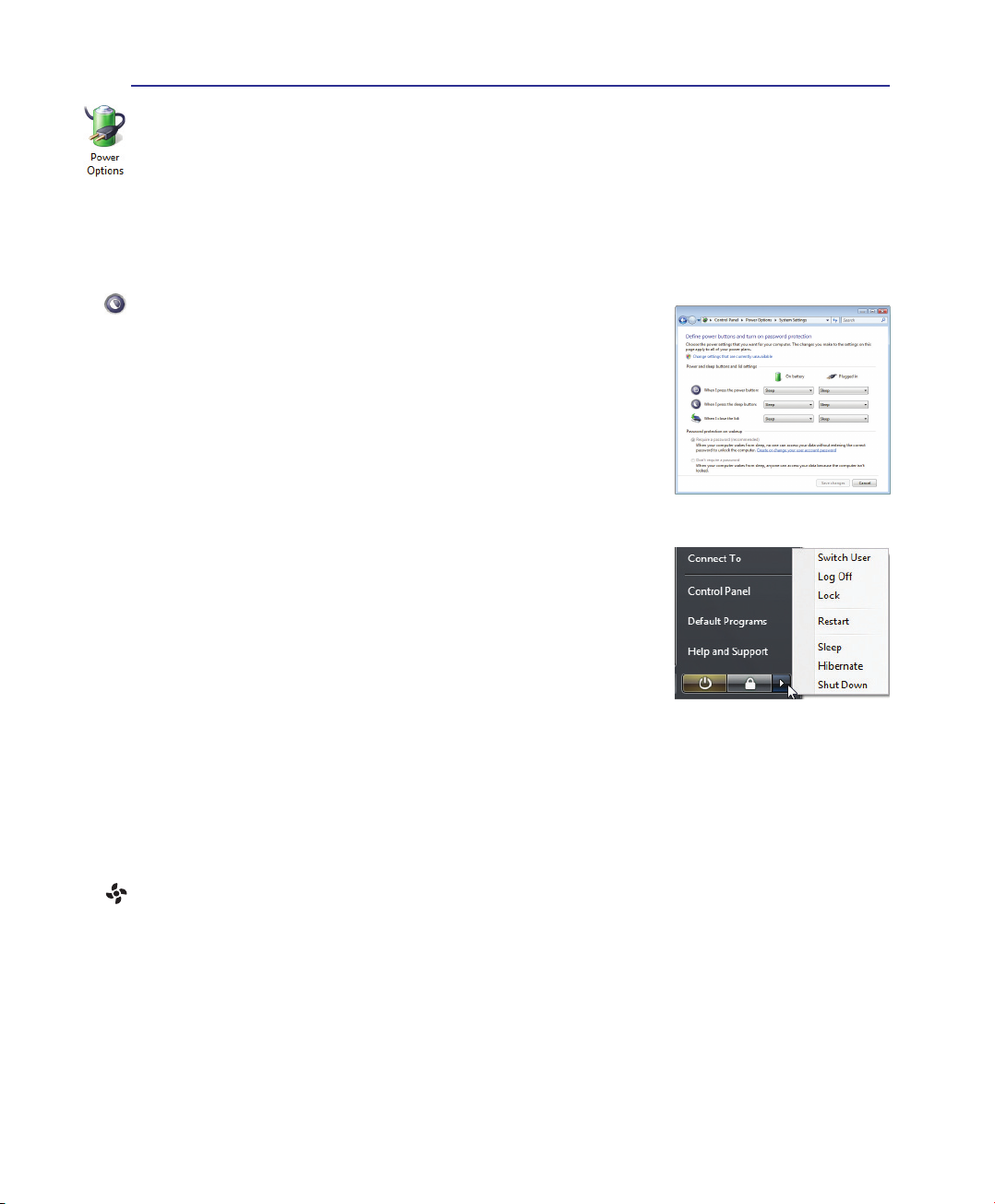
Power management settings can be found in the Windows > Control
Panel > Power Options. In System Settings, you can dene “Sleep/
Hibernate” or “Shut Down” for closing the display panel or pressing the
power button. “Sleep” and “Hibernate” saves power when your Notebook
PC is not in use by turning OFF certain components. When you resume
your work, your last status (such as a document scrolled down half way
or email typed half way) will reappear as if you never left. “Shut Down”
will close all applications and ask if you want to save your work if any
are not saved.
Sleep is the same as Suspend-to-RAM (STR). This function stores your
current data and status in RAM while many components are turned OFF.
Because RAM is volatile, it requires power to keep (refresh) the data.
Click the Start button and the arrowhead next to the lock icon to see this
option. You can also use the keyboard shortcut [Fn F1] to activate this
mode. Recover by pressing any keyboard key except [Fn]. (NOTE: The
power indicator will blink in this mode.)
Hibernate is the same as Suspend-to-Disk (STD) and stores your current data and status on the hard
disk drive. By doing this, RAM does not have to be periodically refreshed and power consumption is
greatly reduced but not completely eliminated because certain wake-up components like LAN needs to
remain powered. “Hibernate” saves more power compared to “Sleep”. Click the Start button and the
arrowhead next to the lock icon to see this option. Recover by pressing the power button. (NOTE: The
power indicator will be OFF in this mode.)
Thermal Power Control
There are three power control methods for controlling the Notebook PC’s thermal state. These power
control cannot be congured by the user and should be known in case the Notebook PC should enter
these states. The following temperatures represent the chassis temperature (not CPU).
• The fan turns ON for active cooling when the temperature reaches the safe upper limit.
• The CPU decreases speed for passive cooling when the temperature exceeds the safe upper limit.
• The system shut down for critical cooling when temperature exceeds the maximum safe upper
limit.
19
Page 20
3 Getting Started
Special Keyboard Functions
Colored Hot Keys
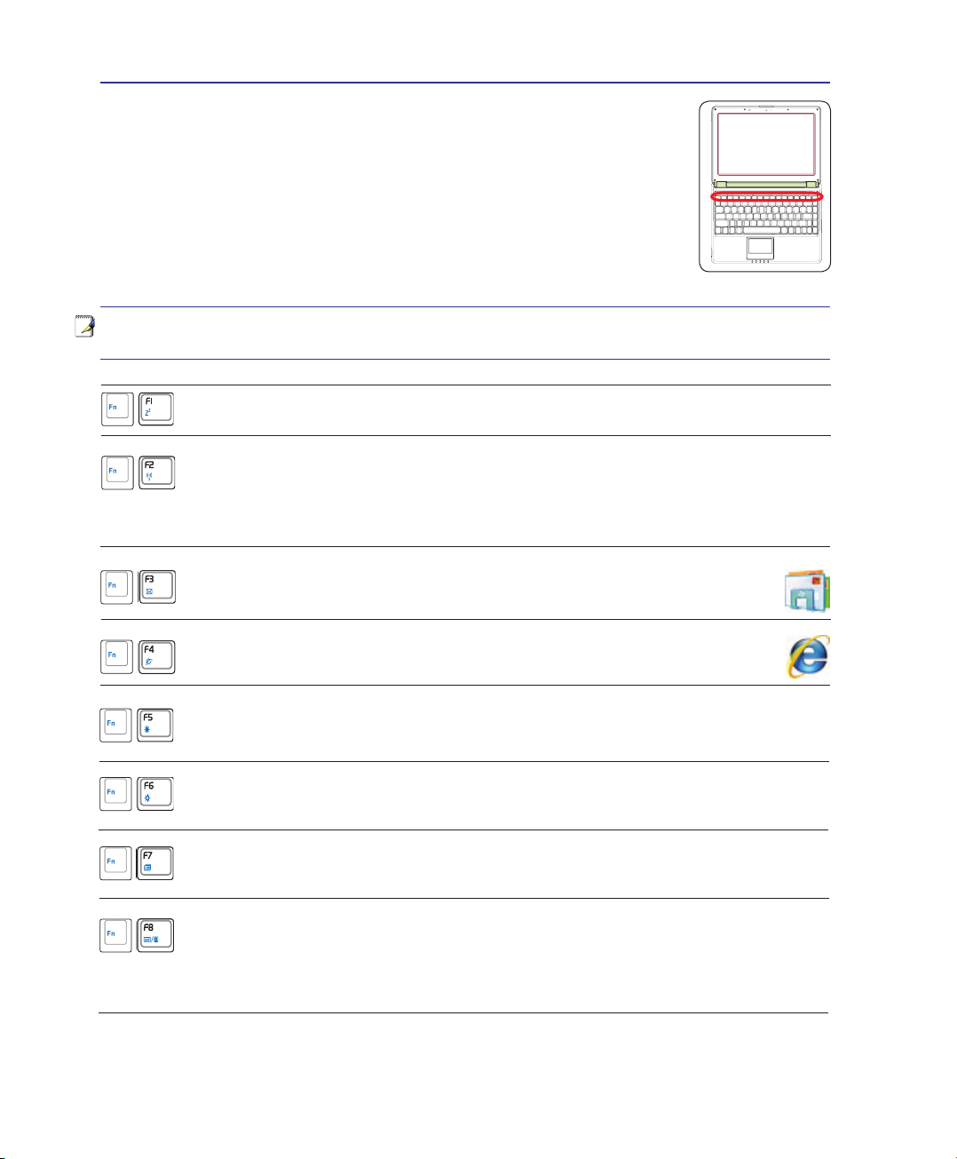
The following denes the colored hot keys on the Notebook PC’s keyboard. The
colored commands can only be accessed by rst pressing and holding the function
key while pressing a key with a colored command.
NOTE: The Hot Key locations on the function keys may vary depending on model but the
functions should remain the same. Follow the icons instead of the function keys.
“Zz” Icon (F1): Places the Notebook PC in suspend mode (either Save-to-RAM or Save-
to-Disk depending on sleep button setting in power management setup).
Radio Tower (F2): Wireless Models Only: Toggles the internal wireless LAN or Bluetooth (on selected models) ON or OFF with an on-screen-display. When enabled, the
corresponding wireless indicator will light. Windows software settings are necessary to
use the wireless LAN or Bluetooth.
Envelope Icon (F3): Pressing this button will launch your Email application
while Windows is running�
20
“e” Icon (F4): Pressing this button will launch your Internet browser applica-
tion while Windows is running�
Filled Sun Icon (F5):
Decreases the display brightness
Open Sun Icon (F6):
Increases the display brightness
LCD Icon (F7): Toggles the display panel ON and OFF. This also stretches your screen area
(on certain models) to ll the entire display when using low resolution modes.
LCD/Monitor Icons (F8): Toggles between the Notebook PC’s LCD display and an external monitor in this series: Notebook PC LCD -> External Monitor -> Both. (This function does not work in
256 Colors, select High Color in Display Property Settings.) IMPORTANT: Connect an external
monitor before booting up the Notebook PC.
Page 21
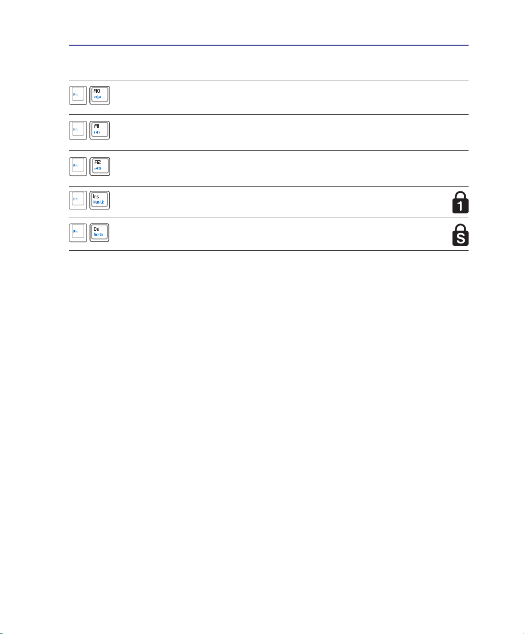
Colored Hot Keys (cont.)
Speaker Icons (F10):
Toggles the speakers ON and OFF (only in Windows OS)
Speaker Down Icon (F11):
Decreases the speaker volume (only in Windows OS)
Speaker Up Icon (F12):
Increases the speaker volume (only in Windows OS)
Num Lk (Ins): Toggles the numeric keypad (number lock) ON and OFF. Allows
you to use a larger portion of the keyboard for number entering.
Scr Lk (Del): Toggles the “Scroll Lock” ON and OFF. Allows you to use a larger
portion of the keyboard for cell navigation.
Getting Started 3
21
Page 22
3 Getting Started
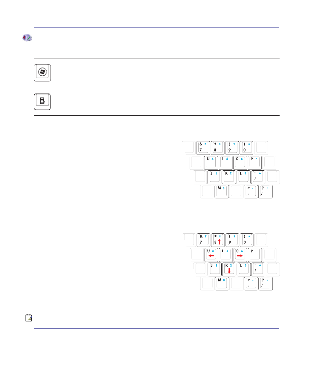
Microsoft Windows Keys
There are two special Windows keys on the keyboard as described below.
The key with the Windows Logo activates the Start menu located at the bottom left of the Windows desktop.
The other key, that looks like a Windows menu with a small cursor, activates the properties menu
and is equivalent to pressing the right mouse button on a Windows object.
Keyboard as a Numeric Keypad
The numeric keypad is embedded in the keyboard and consists
of 15 keys that make number intensive input more convenient.
These dual-purpose keys are labeled in orange on the key caps.
Numeric assignments are located at the upper right hand corner
of each key as shown in the gure. When the numeric keypad is
engaged by pressing [Fn][Ins/Num LK], the number lock LED
lights up. If an external keyboard is connected, pressing the [Ins/
Num LK] on the external keyboard enables/disables the NumLock
on both keyboards simultaneously. To disable the numeric keypad
while keeping the keypad on an external keyboard activated, press the [Fn][Ins/Num LK] keys on the
Notebook PC.
Keyboard as Cursors
The keyboard can be used as cursors while Number Lock is
ON or OFF in order to increase navigation ease while entering
numeric data in spreadsheets or similar applications.
With Number Lock OFF, press [Fn] and one of the cursor keys
shown below. For example [Fn][8] for up, [Fn][K] for down, [Fn]
[U] for left, and [Fn][O] for right.
With Number Lock ON, use [Shift] and one of the cursor keys shown
below. For example [Shift][8] for up, [Shift][K] for down, [Shift][U] for left, and [Shift][O] for right.
NOTE: The red arrows are illustrated here for your reference. They are not labeled on
the keyboard as shown here.
22
Page 23
Getting Started 3
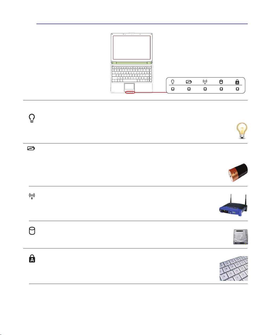
Status Indicators
Power Indicator
The power indicator lights when the Notebook PC is turned ON and blinks slowly when the Notebook PC is in the Suspend-to-RAM (Sleep) mode. This indicator is OFF when the Notebook PC
is turned OFF or in the Suspend-to-Disk (Hibernation) mode.
Battery Charge Indicator
The battery charge indicator is an LED that shows the status of the battery’s power as follows:
ON: The Notebook PC’s battery is charging when AC power is connected.
OFF: The Notebook PC’s battery is charged or completely drained.
Blinking: Battery power is less than 10% and the AC power is not connected.
Wireless Indicator
This is only applicable on models with built-in wireless LAN and/or built-in Bluetooth (on
selected models). When the built-in wireless LAN and/or built-in Bluetooth is enabled,
this indicator will light. (Windows software settings are necessary.)
Drive Activity Indicator
Indicates that the Notebook PC is accessing one or more storage device(s) such as the hard
disk. The light ashes proportional to the access time.
Capital Lock Indicator
Indicates that capital lock [Caps Lock] is activated when lighted. Capital lock allows some
of the keyboard letters to type using capitalized letters (e.g. A, B, C). When the capital
lock light is OFF, the typed letters will be in the lower case form (e.g. a,b,c).
23
Page 24

4 Using the Notebook PC
24
Page 25

4. Using the Notebook PC
Pointing Device
Storage Devices
Flash memory card reader
Optical disc drive
Hard disk drive
Memory (RAM)
Connections
Network connection
Modem connection
Wireless LAN connection (on selected models)
Bluetooth wireless connection (on selected models)
NOTE: Photos and icons in this manual are used for artistic purposes only and do not
show what is actually used in the product itself.
25
Page 26
4 Using the Notebook PC
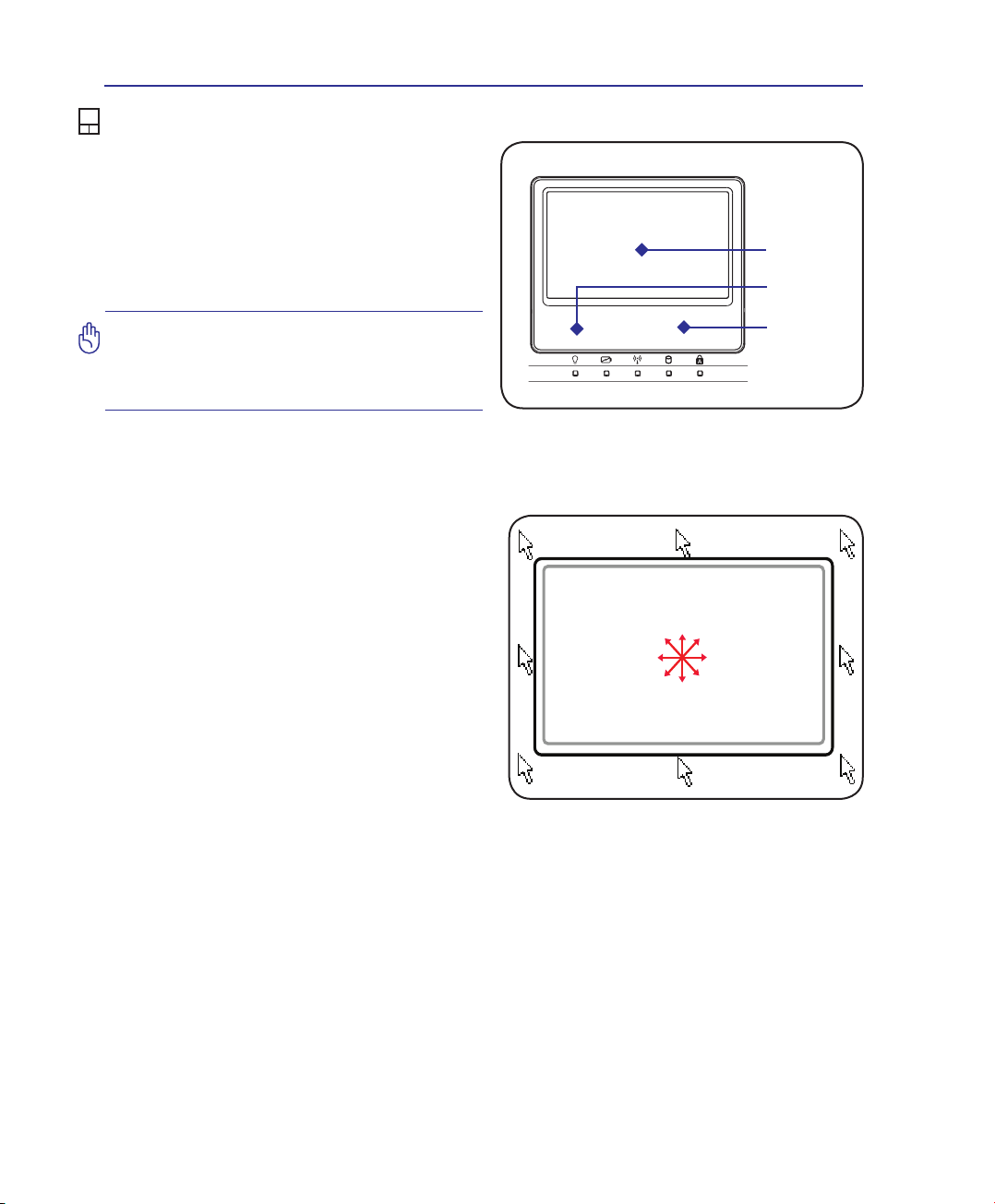
Pointing Device
The Notebook PC’s integrated touchpad pointing device is fully compatible with all two/
three-button and scrolling knob PS/2 mice� The
touchpad is pressure sensitive and contains no
moving parts; therefore, mechanical failures can
be avoided� A device driver is still required for
working with some application software�
Cursor
Movement
Left Click
IMPORTANT! Do not use any objects in
place of your nger to operate the touchpad or else damage may occur to the
touchpad’s surface.
Using the Touchpad
Light pressure with the tip of your nger is all
that is required to operate the touchpad� Because the touchpad is electrostatic sensitive,
objects cannot be used in place of your ngers.
The touchpad’s primary function is to move the
cursor around or select items displayed on the
screen with the use of your ngertip instead
of a standard desktop mouse� The following
illustrations demonstrate proper use of the
touchpad�
Moving The Cursor
Place your nger in the center of the touchpad
and slide in a direction to move the cursor�
Slide nger
left
Slide nger
forward
Slide nger
backward
Right Click
Slide nger
right
26
Page 27
Using the Notebook PC 4
Multi-touch gesture usage
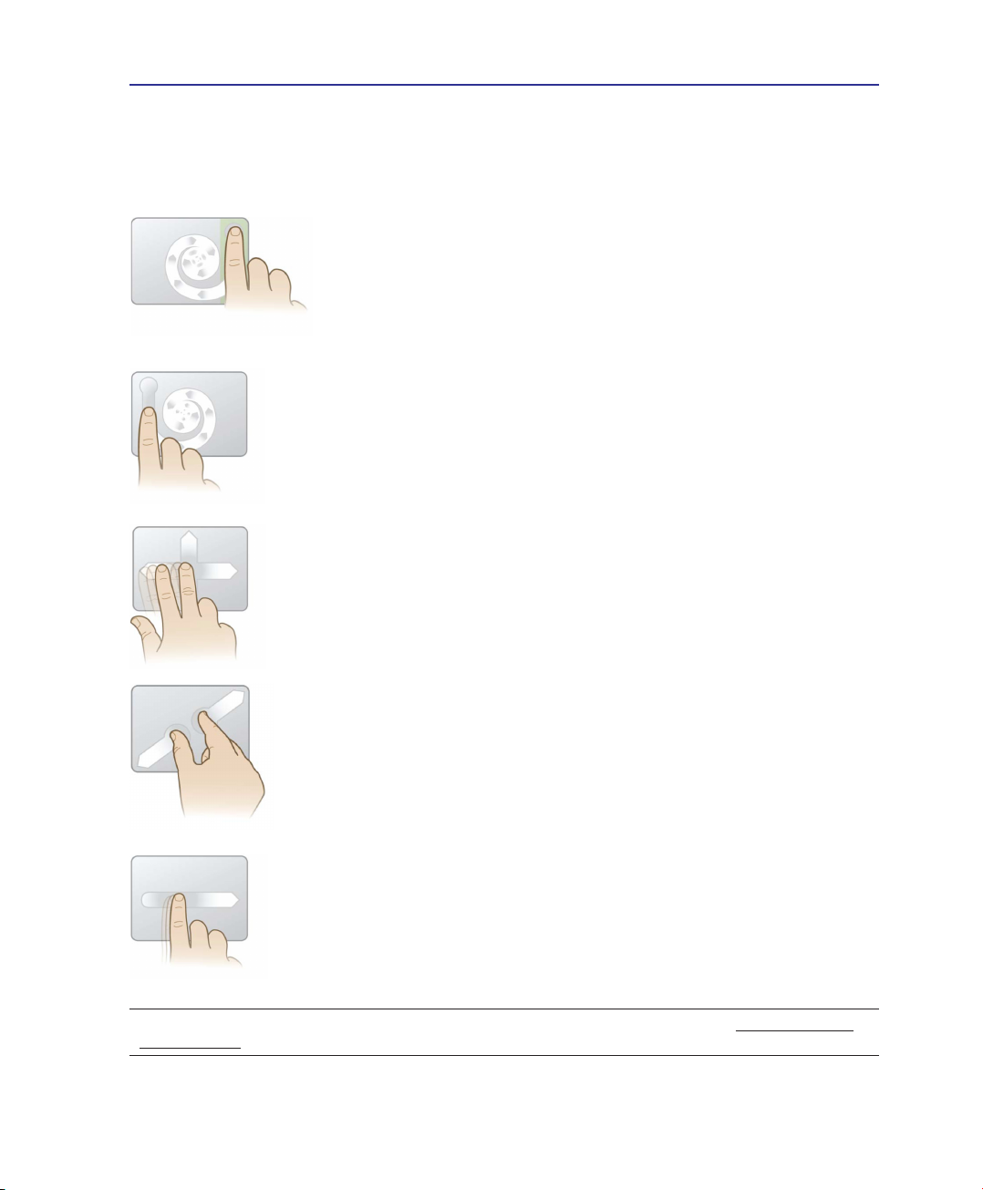
Multi-touch recognizes multiple simultaneous touch points to allow advanced software actions
using just two ngers.
Chiral Scrolling
Touch the vertical scroll zone as shown and then
slide your nger CW or CCW to scroll continuously.
Convenient for scrolling a long document.
Chiral Rotate
Touch the left vertical zone as shown and then slide
your nger CW or CCW for rotating an item, such
as a photo.
Two Fingers Flick
Slide two ngers up/down/left/or right for enhanced
navigation, such as browsing back on the web.
Two Fingers Pinch Zoom
Slide two ngers outwards to zoom in. Slide two
ngers inwards to zoom out. Convenient for viewing
photos.
Momentum Motion
Flick one nger for delivering smooth and fast cursor
motion, like that of a trackball. Convenient for moving
a window onto a secondary monitor.
TIP: For detailed multi-touch gesture usage, please refer to the video demonstration in Mouse Properties >
Device Settings.
27
Page 28
4 Using the Notebook PC
Caring for the Touchpad
The touchpad is pressure sensitive. If not properly cared for, it can be easily damaged. Take note of the
following precautions.
• Make sure the touchpad does not come into contact with dirt, liquids or grease.
• Do not touch the touchpad if your ngers are dirty or wet.
• Do not rest heavy objects on the touchpad or the touchpad buttons.
• Do not scratch the touchpad with your nger nails or any hard objects.
NOTE: The touchpad responds to movement not to force. There is no need to tap
the surface too hard. Tapping too hard does not increase the responsiveness of the
touchpad. The touchpad responds best to light pressure.
Automatic Touchpad Disabling
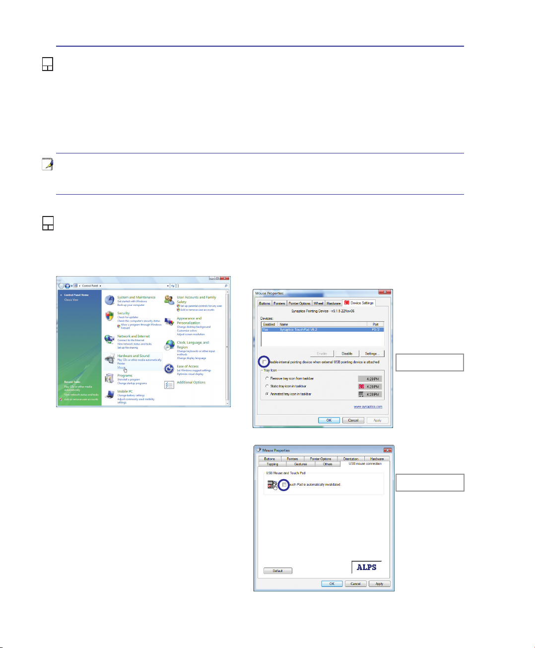
Windows can automatically disable the Notebook PC’s touchpad when an external USB mouse is attached. This feature is normally OFF, to turn ON this feature, select the option in Windows Control
Panel > Mouse Properties > Device Settings.
Models with Synaptics touchpad�
Find Mouse properties in the “Control Panel”�
28
Models with ALPS touchpad�
Select this option to
enable this feature�
Select this option to
enable this feature�
Page 29
Using the Notebook PC 4
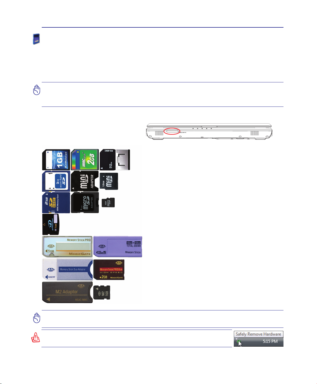
Memory Stick Duo/Duo Pro/MagicGate (with MS adapater)
SD (Secure Digital)
miniSD (with SD adapter)
SDHC (Secure Digital High Capacity)
microSD (with SD adapter)
Memory Stick Micro (with MS adapter)
xD-Picture Card
MMC (Multimedia Card)
MMC Plus
RS-MMC (Reduced Size) (with MMC adapter)
Memory stick (MS) / PRO / MagicGate / Select
Flash Memory Card Reader
Normally a memory card reader must be purchased separately in order to use memory cards from devices
such as digital cameras, MP3 players, mobile phones, and PDAs. This Notebook PC has a single built-in
memory card reader that can use many ash memory cards as shown in the example below. The built-in
memory card reader is not only convenient, but also faster than most other forms of memory card readers
because it utilizes the internal high-bandwidth PCI bus.
IMPORTANT! Flash memory card compatibility varies depending on Notebook PC model
and ash memory card specications. Flash memory card specications constantly
change so compatibility may change without warning.
Flash Memory Card Examples
IMPORTANT! Never remove cards while or immediately after reading, copying, formatting, or deleting data on the card or else data loss may occur.
WARNING! To prevent data loss, use “Windows Safely Remove Hard-
ware” on the taskbar before removing the ash memory card.
29
Page 30
4 Using the Notebook PC
Optical Drive
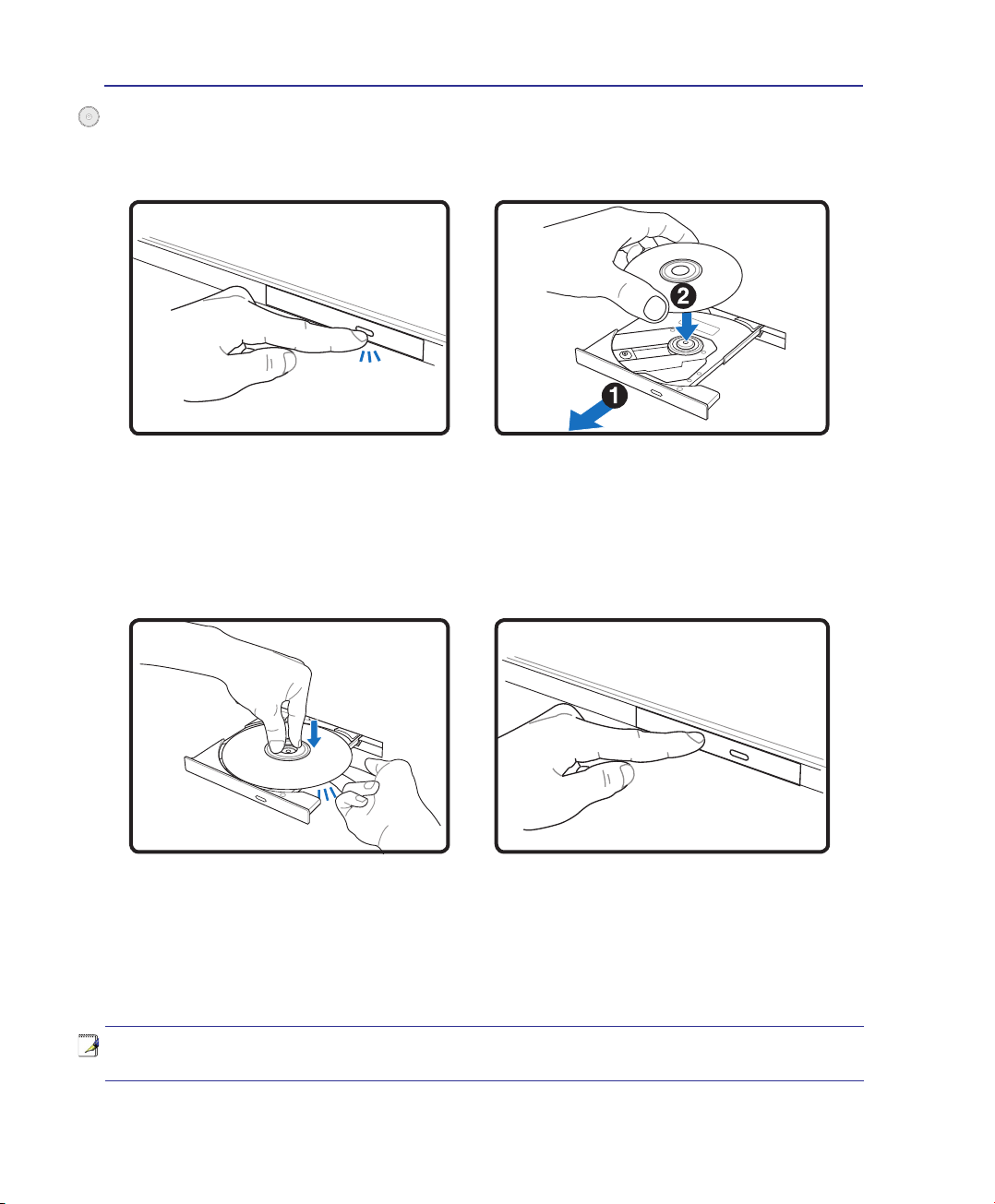
Inserting an optical disc
1. While the Notebook PC’s power is ON, press
the drive’s eject button and the tray will eject
out partially.
3. Hold the disc by the edge and face the disc’s
printed side up. Push down on both sides of
the disc’s center until the disc snaps onto the
hub. The hub should be higher than
the disc when correctly mounted.
2. Gently pull on the drive’s front panel and slide
the tray completely out. Be careful not to touch
the CD drive lens and other mechanisms. Make
sure there are no obstructions that may get
jammed under the drive’s tray.
4. Slowly push the drive’s tray back in. The drive
will begin reading the table of contents (TOC)
on the disc. When the drive stops, the disc is
ready to be used.
NOTE: It is normal to hear as well as feel the CD spinning with great intensity in the
CD drive while data is read.
30
Page 31
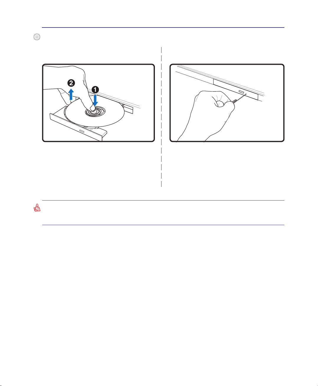
Optical Drive (Cont.)
Using the Notebook PC 4
Removing an optical disc
Eject the tray and gently pry the edge of the
disc upwards at an angle to remove the disc
from the hub�
WARNING! If the CD disc is not properly locked onto the center hub, the CD can be
damaged when the tray is closed. Always watch the CD closely while closing the tray
slowly to prevent damage.
Emergency eject
Actual location will
vary by model�
The emergency eject is located in a hole on
the optical drive and is used to eject the optical drive tray in case the electronic eject does
not work� Do not use the emergency eject in
place of the electronic eject�
31
Page 32
4 Using the Notebook PC
L
L
L
L
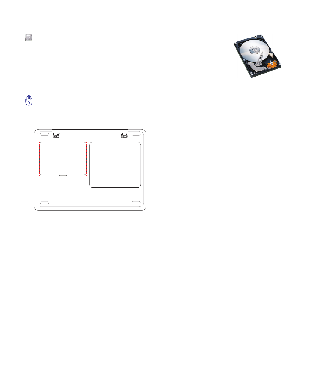
Hard Disk Drive
Hard disk drives have higher capacities and operate at much faster speeds than oppy
disk drives and optical drives. The Notebook PC comes with a replaceable hard
disk drive. Current hard drives support S.M.A.R.T. (Self Monitoring and Reporting
Technology) to detect hard disk errors or failures before they happen. When replacing
or upgrading the hard drive, always visit an authorized service center or retailer for this
Notebook PC.
IMPORTANT! Poor handling of the Notebook PC may damage the hard disk drive.
Handle the Notebook PC gently and keep it away from static electricity and strong
vibrations or impact. The hard disk drive is the most delicate component and will likely
be the rst or only component that is damaged if the Notebook PC is dropped.
Hard Disk Drive Compartment
The hard disk drive is secured in a compartment. Visit
an authorized service center or retailer for information on hard disk drive upgrades for your Notebook
PC. Only purchase hard disk drives from authorized
retailers of this Notebook PC to ensure maximum
compatibility and reliability.
32
Page 33
Using the Notebook PC 4
3
L
L
L
L
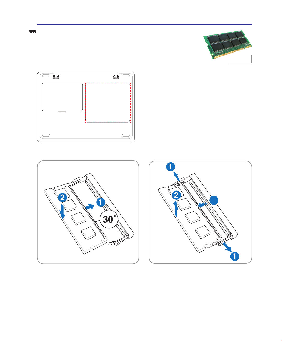
Memory (RAM)
Additional memory will increase application performance by decreasing hard
disk access. The BIOS automatically detects the amount of memory in the system
and congures CMOS accordingly during the POST (Power-On-Self-Test) process.
There is no hardware or software (including BIOS) setup required after the memory
is installed.
The memory compartment provides expansion capabilities for additional memory. Visit an authorized
service center or retailer for information on memory
upgrades for your Notebook PC. Only purchase
expansion modules from authorized retailers of this
Notebook PC to ensure maximum compatibility and
reliability.
This is only
an example�
Installing a Memory Card:
(This is only an example�) (This is only an example�)
Removing a Memory Card:
33
Page 34
4 Using the Notebook PC
Connections
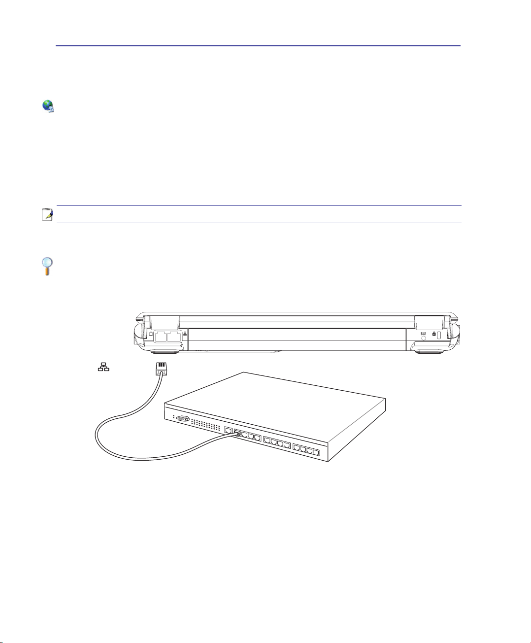
Network Connection
Connect a network cable, with RJ-45 connectors on each end, to the modem/network port on the Notebook PC and the other end to a hub or switch. For 100 BASE-TX / 1000 BASE-T speeds, your network
cable must be category 5 or better (not category 3) with twisted-pair wiring. If you plan on running the
interface at 100/1000Mbps, it must be connected to a 100 BASE-TX / 1000 BASE-T hub (not a BASE-T4
hub). For 10Base-T, use category 3, 4, or 5 twisted-pair wiring. 10/100 Mbps Full-Duplex is supported
on this Notebook PC but requires connection to a network switching hub with “duplex” enabled. The
software default is to use the fastest setting so no user-intervention is required.
1000BASE-T (or Gigabit) is only supported on selected models.
Example of the Notebook PC connected to a Network Hub or Switch for use with the
built-in Ethernet controller.
34
LAN
connector is the
larger of the two�
Network Hub or Switch
Network cable with RJ-45 connectors
Page 35
Using the Notebook PC 4
Modem Connection
NOTE: The built-in modem and network cannot be installed later as an upgrade. After
purchase, modem and/or network can be installed as an expansion card.
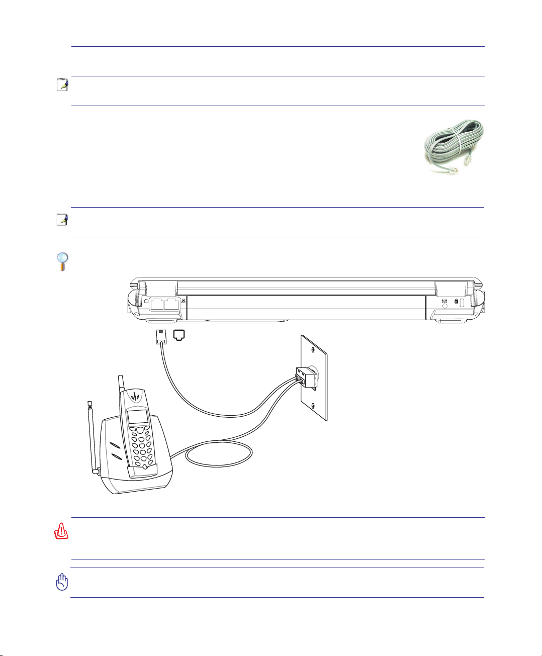
The telephone wire used to connect the Notebook PC’s internal modem should
have either two or four wires (only two wires (telephone line #1) is used by
the modem) and should have an RJ-11 connector on both ends� Connect one
end to the modem port and the other end to an analog telephone wall socket
(the ones found in residential buildings)� Once the driver is setup, the modem
is ready to use�
NOTE: When you are connected to an online service, do not place the Notebook PC
in suspend (or sleep mode) or else you will disconnect the modem connection.
Example of the Notebook PC connected to a telephone jack for use with the built-in
modem:
Telephone connector is
the smaller of the two.
Telephone Wall
Jack
Telephone
connection is
optional
Telephone cables
with RJ-11 connectors
WARNING! Only use analog telephone outlets. The built-in modem does not support
the voltage used in digital phone systems. Do not connect the RJ-11 to digital phone
systems found in many commercial buildings or else damage will occur!
CAUTION: For electrical safety concerns, only use telephone cables rated 26AWG or
higher. (see Glossary for more information)
35
Page 36
4 Using the Notebook PC
Wireless LAN Connection (on selected models)
The optional built-in wireless LAN is a compact easy-to-use wireless Ethernet adapter. Implementing
the IEEE 802.11 standard for wireless LAN (WLAN), the optional built-in wireless LAN is capable of
fast data transmission rates using Direct Sequence Spread Spectrum (DSSS) and Orthogonal Frequency
Division Multiplexing (OFDM) technologies on 2.4GHz/5GHz frequencies. The optional built-in wire-
less LAN is backward compatible with the earlier IEEE 802.11 standards allowing seamless interfacing
of wireless LAN standards.
The optional built-in wireless LAN is a client adapter that supports Infrastructure and Ad-hoc modes
giving you exibility on your existing or future wireless network congurations for distances up to 40
meters between the client and the access point.
To provide efcient security to your wireless communication, the optional built-in wireless LAN comes
with a 64-bit/128-bit Wired Equivalent Privacy (WEP) encryption and Wi-Fi Protected Access (WPA)
features.
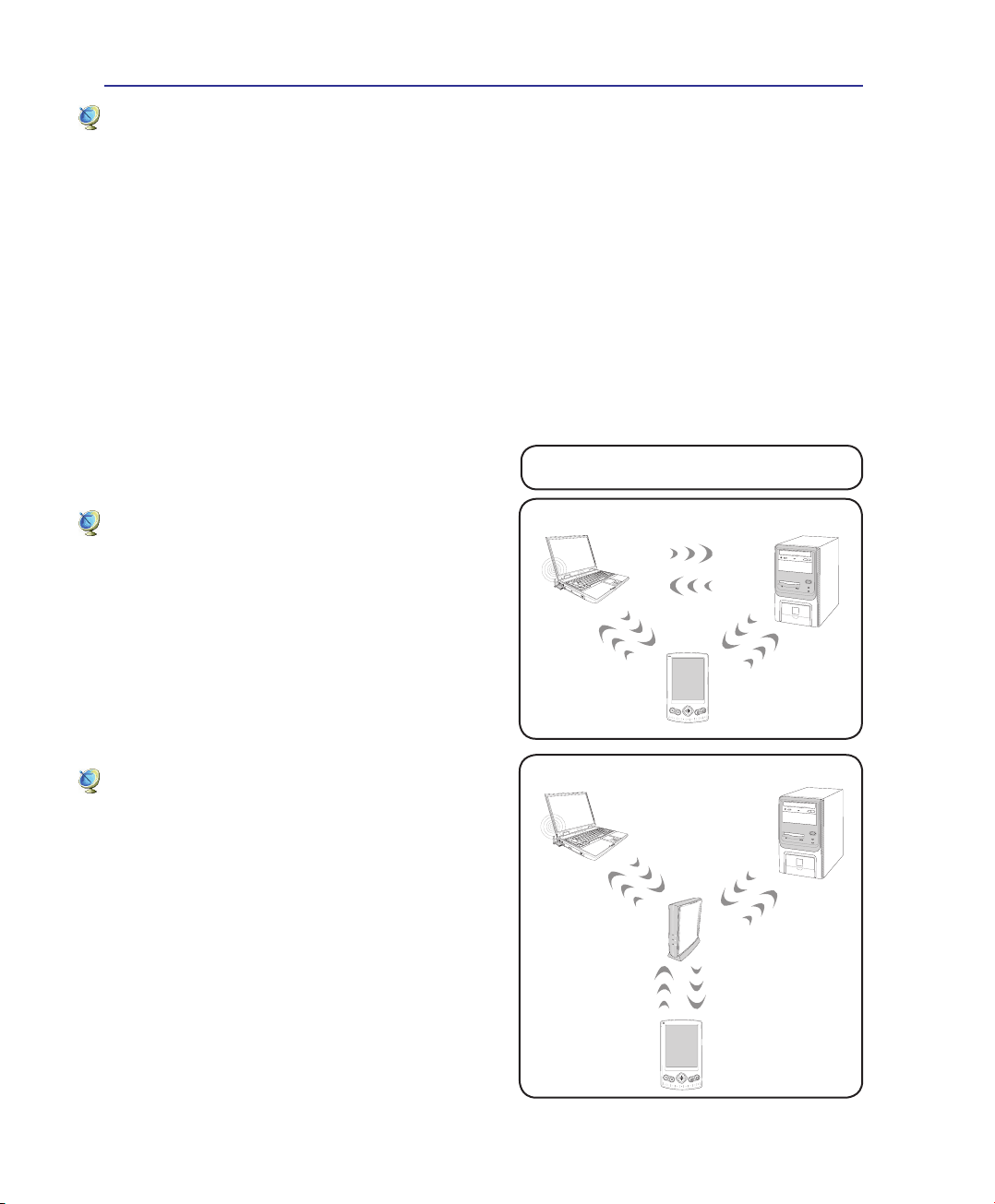
These are examples of the Notebook PC
connected to a Wireless Network�
Ad-hoc mode
The Ad-hoc mode allows the Notebook PC to connect
to another wireless device. No access point (AP) is
required in this wireless environment.
(All devices must install optional 802�11 wireless LAN adapters�)
Infrastructure mode
The Infrastructure mode allows the Notebook PC and
other wireless devices to join a wireless network created by an Access Point (AP) (sold separately) that
provides a central link for wireless clients to communicate with each other or with a wired network.
(All devices must install optional 802�11 wireless LAN adapters�)
Notebook PC
Notebook PC
PDA
Access
Point
Desktop PC
Desktop PC
36
PDA
Page 37
Using the Notebook PC 4
Windows Wireless Network Connection
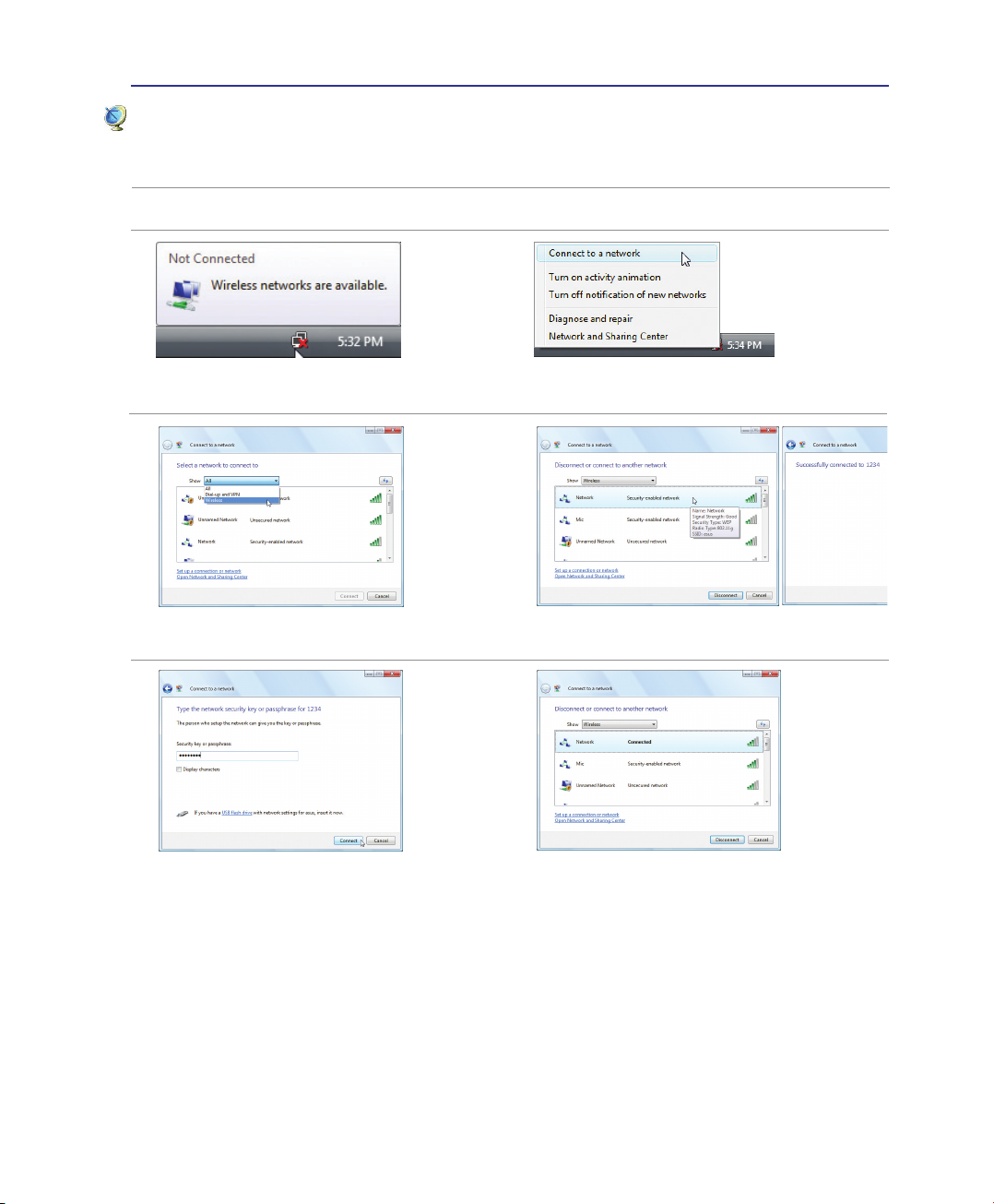
Connecting to a network
1� Switch ON the Wireless function if necessary for your model (see switches in Section 3)�
2� You should see the “Not Connected” network
icon�
4� Select “Show Wireless” if you have many
networks in your area�
6� When connecting, you may have to enter a
password�
3� Right click on the network icon and select
Connect to a network�
5� Select the wireless network you want to con-
nect to�
7� After connection has been established, “Con-
nected” will be shown�
37
Page 38
4 Using the Notebook PC
Bluetooth Wireless Connection (on selected models)
Notebook PCs with Bluetooth technology eliminates the need for cables for connecting
Bluetooth-enabled devices. Examples of Bluetooth-enabled devices may be Notebook PCs,
Desktop PCs, mobile phones, and PDAs.
Note: If your Notebook PC did not come with built-in Bluetooth, you need to connect
a USB or ExpressCard Bluetooth module in order to use Bluetooth.
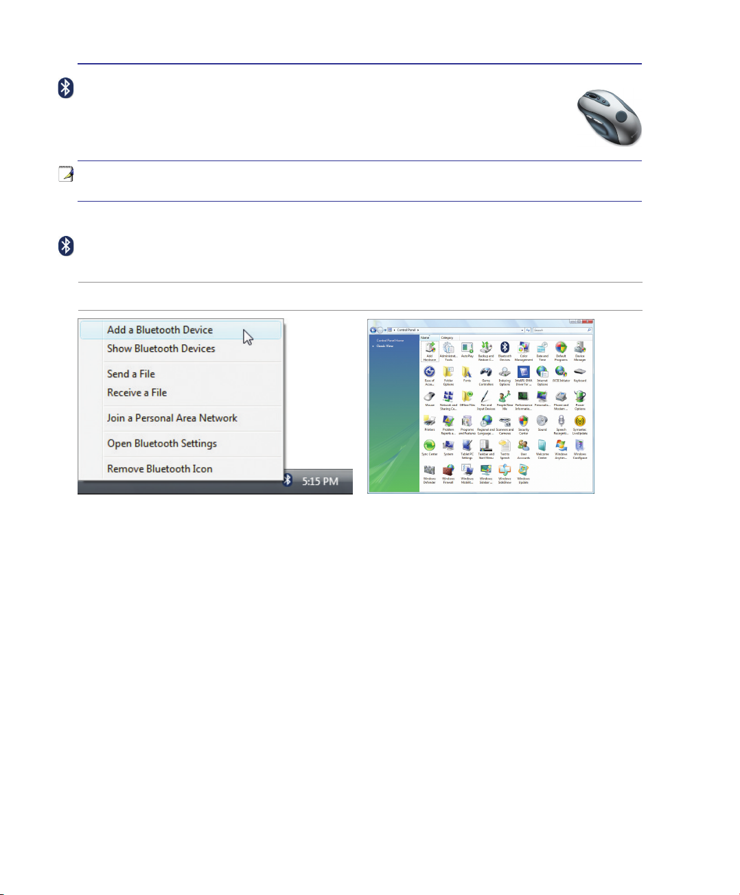
Turning ON and Launching Bluetooth Utility
This process can be used to add most Bluetooth devices. See Appendix for complete process.
1� Switch ON the Wireless function if necessary for your model (see switches in Section 3)�
2� Select Add a Bluetooth Device on the taskbar
men�
38
2b� Or Launch Bluetooth Devices from the Windows
Control Panel�
Page 39
A-29
Appendix A
Nordic Lithium Cautions (for lithium-ion batteries)
CAUTION! Danger of explosion if battery is incorrectly replaced. Replace only
with the same or equivalent type recommended by the manufacturer. Dispose of used
batteries according to the manufacturer’s instructions. (English)
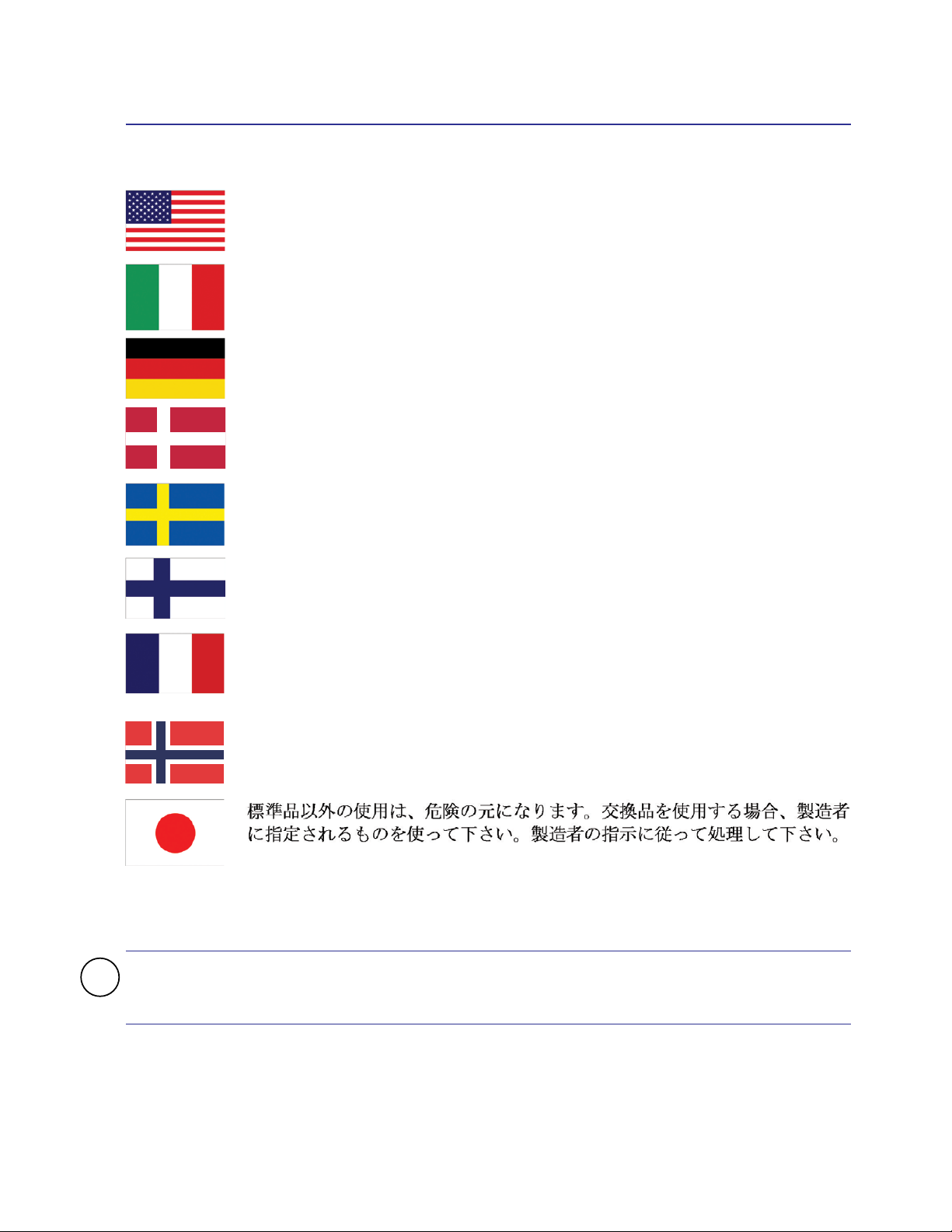
ATTENZIONE! Rischio di esplosione della batteria se sostituita in modo errato.
Sostituire la batteria con un una di tipo uguale o equivalente consigliata dalla fabbrica. Non disperdere le batterie nell’ambiente. (Italian)
VORSICHT! Explosionsgefahr bei unsachgemäßen Austausch der Batterie. Ersatz nur durch denselben oder einem vom Hersteller empfohlenem ähnlichen Typ.
Entsorgung gebrauchter Batterien nach Angaben des Herstellers. (German)
ADVARSELI! Lithiumbatteri - Eksplosionsfare ved fejlagtig håndtering. Udskiftning
må kun ske med batteri af samme fabrikat og type. Levér det brugte batteri tilbage til
leverandøren. (Danish)
VARNING! Explosionsfara vid felaktigt batteribyte. Använd samma batterityp eller en
ekvivalent typ som rekommenderas av apparattillverkaren. Kassera använt batteri enligt
fabrikantens instruktion. (Swedish)
Hg
VAROITUS! Paristo voi räjähtää, jos se on virheellisesti asennettu. Vaihda paristo
ainoastaan laitevalmistajan sousittelemaan tyyppiin. Hävitä käytetty paristo valmistagan
ohjeiden mukaisesti. (Finnish)
ATTENTION! Il y a danger d’explosion s’il y a remplacement incorrect de la batterie. Remplacer uniquement avec une batterie du mêre type ou d’un type équivalent
recommandé par le constructeur. Mettre au rebut les batteries usagées conformément
aux instructions du fabricant. (French)
ADVARSEL! Eksplosjonsfare ved feilaktig skifte av batteri. Benytt samme batteritype eller en tilsvarende type anbefalt av apparatfabrikanten. Brukte batterier kasseres
i henhold til fabrikantens instruksjoner. (Norwegian)
(Japanese)
IMPORTANT! Depending on model, components used in the Notebook PC display
panel may contain mercury. Recycle or dispose according to local, state, and federal
laws.
Page 40
Appendix A
Optical Drive Safety Information
Laser Safety Information
Internal or external optical drives sold with this Notebook PC contains a CLASS 1 LASER PROD-
UCT. Laser classications can be found in the glossary at the end of this user’s manual.
WARNING: Making adjustments or performing procedures other than those specied
in the user’s manual may result in hazardous laser exposure. Do not attempt to disassemble the optical drive. For your safety, have the optical drive serviced only by an
authorized service provider.
Service warning label
CAUTION: INVISIBLE LASER RADIATION WHEN OPEN. DO NOT STARE INTO BEAM
OR VIEW DIRECTLY WITH OPTICAL INSTRUMENTS.
CDRH Regulations
The Center for Devices and Radiological Health (CDRH) of the U�S� Food and Drug Administration implemented regulations for laser products on August 2, 1976� These regulations apply
to laser products manufactured from August 1, 1976� Compliance is mandatory for products
marketed in the United States�
WARNING: Use of controls or adjustments or performance of procedures other than
those specied herein or in the laser product installation guide may result in hazardous radiation exposure.
Macrovision Corporation Product Notice
This product incorporates copyright protection technology that is protected by method claims
of certain U�S�A� patents and other intellectual property rights owned by Macrovision Corporation and other rights owners� Use of this copyright protection technology must be authorized
by Macrovision Corporation, and is intended for home and other limited viewing uses only unless otherwise authorized by Macrovision Corporation� Reverse engineering or disassembly
is prohibited�
51
 Loading...