

ASRock FM2A75 Pro4 Owner's Manual

FM2A75 Pro4
User Manual
Version 1.1
Published July 2013
Copyright©2013 ASRock INC. All rights reserved.
1

Copyright Notice:
No part of this manual may be reproduced, transcribed, transmitted, or translated in
any language, in any form or by any means, except duplication of documentation by
the purchaser for backup purpose, without written consent of ASRock Inc.
Products and corporate names appearing in this manual may or may not be regis-
tered trademarks or copyrights of their respective companies, and are used only for
identication or explanation and to the owners’ benet, without intent to infringe.
Disclaimer:
Specications and information contained in this manual are furnished for informa-
tional use only and subject to change without notice, and should not be constructed
as a commitment by ASRock. ASRock assumes no responsibility for any errors or
omissions that may appear in this manual.
With respect to the contents of this manual, ASRock does not provide warranty of
any kind, either expressed or implied, including but not limited to the implied warran-
ties or conditions of merchantability or tness for a particular purpose.
In no event shall ASRock, its directors, ofcers, employees, or agents be liable for
any indirect, special, incidental, or consequential damages (including damages for
loss of prots, loss of business, loss of data, interruption of business and the like),
even if ASRock has been advised of the possibility of such damages arising from
any defect or error in the manual or product.
This device complies with Part 15 of the FCC Rules. Operation is subject to the fol-
lowing two conditions:
(1) this device may not cause harmful interference, and
(2) this device must accept any interference received, including interference that
may cause undesired operation.
CALIFORNIA, USA ONLY
The Lithium battery adopted on this motherboard contains Perchlorate, a toxic
substance controlled in Perchlorate Best Management Practices (BMP) regulations
passed by the California Legislature. When you discard the Lithium battery in Cali-
fornia, USA, please follow the related regulations in advance.
“Perchlorate Material-special handling may apply, see
www.dtsc.ca.gov/hazardouswaste/perchlorate”
ASRock Website: http://www.asrock.com
2

Contents
1. Introduction ................................................................ 5
1.1 Package Contents ..................................................................... 5
1.2 Specications ............................................................................. 6
1.3 Unique Features ........................................................................ 10
1.4 Motherboard Layout ................................................................. 14
1.5 I/O Panel .................................................................................. 15
2. Installation .................................................................. 17
Pre-installation Precautions ................................................................ 17
2.1 CPU Installation ......................................................................... 18
2.2 Installation of CPU Fan and Heatsink ...................................... 18
2.3 Installation of Memory Modules (DIMM) .................................... 19
2.4 Expansion Slots (PCI and PCI Express Slots) ........................... 21
2.5 CrossFireXTM and Quad CrossFireXTM Operation Guide ............ 22
2.6 Dual Graphics Operation Guide ................................................ 26
2.7 Dual Monitor and Surround Display Features ........................... 28
2.8 ASRock Smart Remote Installation Guide ................................. 31
2.9 Jumpers Setup ........................................................................... 33
2.10 Onboard Headers and Connectors ....................................... 34
2.11 Smart Switches .......................................................................... 39
2.12 Dr. Debug .............................................................................. 40
2.13 Serial ATA3 (SATA3) Hard Disks Installation ......................... 44
2.14 Hot Plug and Hot Swap Functions for SATA3 HDDs ................. 44
2.15 SATA3 HDD Hot Plug and Hot SwapFeature and Operation
Operation Guide ........................................................................ 45
2.16 Driver Installation Guide ............................................................ 47
2.17 Installing Windows® 7 / 7 64-bit / VistaTM / Vista
With RAID Functions ................................................................. 47
2.18 Installing Windows® 7 / 7 64-bit / VistaTM / Vista
Without RAID Functions ............................................................ 48
TM
TM
64-bit
64-bit
3

3. UEFI SETUP UTILITY .................................................. 49
3.1 Introduction ................................................................................ 49
3.1.1 UEFI Menu Bar ................................................................ 49
3.1.2 Navigation Keys ............................................................... 50
3.2 Main Screen ............................................................................... 50
3.3 OC Tweaker Screen................................................................... 51
3.4 Advanced Screen ...................................................................... 55
3.4.1 CPU Conguration ........................................................... 56
3.4.2 North Bridge Conguration .............................................. 57
3.4.3 South Bridge Conguration ............................................. 58
3.4.4 Storage Conguration ...................................................... 59
3.4.5 Super IO Conguration .................................................... 60
3.4.6 ACPI Conguration .......................................................... 61
3.4.7 USB Conguration ........................................................... 63
3.4.8 Network Conguration ..................................................... 64
3.5 Tool ............................................................................................ 65
3.6 Hardware Health Event Monitoring Screen ............................... 67
3.7 Boot Screen ............................................................................... 69
3.8 Security Screen ......................................................................... 71
3.9 Exit Screen ................................................................................ 73
4. Software Support ....................................................... 74
4.1 Install Operating System ............................................................ 74
4.2 Support CD Information ............................................................. 74
4.2.1 Running Support CD ....................................................... 74
4.2.2 Drivers Menu ................................................................... 74
4.2.3 Utilities Menu ................................................................... 74
4.2.4 Contact Information ......................................................... 74
4
1. Introduction
Thank you for purchasing ASRock FM2A75 Pro4 motherboard, a reliable mother-
board produced under ASRock’s consistently stringent quality control. It delivers
excellent performance with robust design conforming to ASRock’s commitment to
quality and endurance.
In this manual, chapter 1 and 2 contain introduction of the motherboard and step-
by-step guide to the hardware installation. Chapter 3 and 4 contain the conguration
guide to BIOS setup and information of the Support CD.
Because the motherboard specications and the BIOS software might
be updated, the content of this manual will be subject to change without
notice. In case any modications of this manual occur, the updated ver-
sion will be available on ASRock website without further notice. You may
nd the latest VGA cards and CPU support lists on ASRock website as
well. ASRock website http://www.asrock.com
If you require technical support related to this motherboard, please visit
our website for specic information about the model you are using.
www.asrock.com/support/index.asp
1.1 Package Contents
ASRock FM2A75 Pro4 Motherboard
(ATX Form Factor: 12.0-in x 8.8-in, 30.5 cm x 22.4 cm)
ASRock FM2A75 Pro4 Quick Installation Guide
ASRock FM2A75 Pro4 Support CD
4 x Serial ATA (SATA) Data Cables (Optional)
1 x I/O Panel Shield
ASRock Reminds You...
To get better performance in Windows® 7 / 7 64-bit / VistaTM / VistaTM 64
bit, it is recommended to set the BIOS option in Storage Conguration to
AHCI mode.
5

1.2 Specications
Platform - ATX Form Factor: 12.0-in x 8.8-in, 30.5 cm x 22.4 cm
- All Solid Capacitor design
CPU - Support for Socket FM2 100W processors
- 4 + 2 Power Phase Design
- Supports AMD’s Cool ‘n’ QuietTM Technology
- UMI-Link GEN2
Chipset - AMD A75 FCH (Hudson-D3)
Memory - Dual Channel DDR3 Memory Technology
- 4 x DDR3 DIMM slots
- Support DDR3 2600+(OC)/2400(OC)/2133(OC)/1866/1600/
1333/1066/800 non-ECC, un-buffered memory
(see CAUTION 1)
* 2600+ is only supported with two DIMMs
- Max. capacity of system memory: 64GB (see CAUTION 2)
- Supports Intel® Extreme Memory Prole (XMP) 1.3 / 1.2
- Supports AMD Memory Prole (AMP)
Expansion Slot - 2 x PCI Express 2.0 x16 slots
(PCIE2 @ x16 mode; PCIE4 @ x4 mode)
- 2 x PCI Express 2.0 x1 slots
- 3 x PCI slots
- Supports AMD Quad CrossFireXTM, CrossFireXTM and Dual
Graphics
Graphics - AMD Radeon HD 7000 graphics
- DirectX 11, Pixel Shader 5.0
- Max. shared memory 2GB
- Three VGA Output options: D-Sub, DVI-D and HDMI
- Supports HDMI 1.4a Technology with max. resolution up to
1920x1200 @ 60Hz
- Supports Dual-link DVI with max. resolution up to
2560x1600 @ 75Hz
- Supports D-Sub with max. resolution up to 1920x1600 @
60Hz
- Supports Auto Lip Sync, Deep Color (12bpc), xvYCC and
HBR (High Bit Rate Audio) with HDMI (Compliant HDMI
monitor is required) (see CAUTION 3)
- Supports Blu-ray Stereoscopic 3D with HDMI 1.4a
- Supports AMD Steady VideoTM: New video post processing
capability for automatic jutter reduction on home/online
video
6

- Supports HDCP function with DVI and HDMI ports
- Supports Full HD 1080p Blu-ray (BD) / HD-DVD playback
with DVI and HDMI ports
Audio - 7.1 CH HD Audio with Content Protection
(Realtek ALC892 Audio Codec)
- Premium Blu-ray audio support
LAN - PCIE x1 Gigabit LAN 10/100/1000 Mb/s
- Realtek RTL8111E
- Supports Wake-On-LAN
- Supports LAN Cable Detection
- Supports Energy Efcient Ethernet 802.3az
- Supports PXE
Rear Panel I/O I/O Panel
- 1 x PS/2 Mouse/Keyboard Port
- 1 x D-Sub Port
- 1 x DVI-D Port
- 1 x HDMI Port
- 1 x Optical SPDIF Out Port
- 2 x Ready-to-Use USB 2.0 Ports
- 1 x eSATA3 Connector
- 6 x Ready-to-Use USB 3.0 Ports
- 1 x RJ-45 LAN Port with LED (ACT/LINK LED and SPEED
LED)
- 1 x Clear CMOS Switch with LED
- HD Audio Jack: Rear Speaker/Central/Bass/Line in/Front
Speaker/Microphone
SATA3 - 5 x SATA3 6.0 Gb/s connectors, support RAID (RAID 0,
RAID 1 and RAID 10), NCQ, AHCI and “Hot Plug” functions
USB 3.0 - 2 x Rear USB 3.0 ports by AMD A75 FCH (Hudson-D3),
support USB 1.1/2.0/3.0 up to 5Gb/s
- 4 x Rear USB 3.0 ports by Etron EJ188, support
USB 1.1/2.0/3.0 up to 5Gb/s
- 1 x Front USB 3.0 header (supports 2 USB 3.0 ports) by
AMD A75 FCH (Hudson-D3), supports USB 1.1/2.0/3.0 up
to 5Gb/s
Connector - 5 x SATA3 6.0Gb/s connectors
- 1 x IR header
- 1 x CIR header
- 1 x COM port header
- 1 x HDMI_SPDIF header
- 1 x Power LED header
7

- 2 x CPU Fan connectors (1 x 4-pin, 1 x 3-pin)
- 3 x Chassis Fan connectors (1 x 4-pin, 2 x 3-pin)
- 1 x Power Fan connector (3-pin)
- 24 pin ATX power connector
- 8 pin 12V power connector
- Front panel audio connector
- 3 x USB 2.0 headers (support 6 USB 2.0 ports)
- 1 x USB 3.0 header (supports 2 USB 3.0 ports)
- 1 x Dr. Debug (7-Segment Debug LED)
- 1 x Power Switch with LED
- 1 x Reset Switch with LED
- 1 x Clear CMOS Switch with LED
BIOS Feature - 64Mb AMI UEFI Legal BIOS with GUI support
- Supports “Plug and Play”
- ACPI 1.1 Compliance Wake Up Events
- Supports jumperfree
- SMBIOS 2.3.1 Support
- DRAM, VDDP, VDDR, SB Voltage Multi-adjustment
Support CD - Drivers, Utilities, AntiVirus Software (Trial Version),
CyberLink MediaEspresso 6.5 Trial
Hardware - CPU Temperature Sensing
Monitor - Chassis Temperature Sensing
- CPU/Chassis/Power Fan Tachometer
- CPU Quiet Fan
- CPU/Chassis Fan Multi-Speed Control
- Voltage Monitoring: +12V, +5V, +3.3V, Vcore
OS - Microsoft® Windows® 7 / 7 64-bit / Vista
TM
/ VistaTM 64-bit
compliant
Certications - FCC, CE, WHQL
- ErP/EuP Ready (ErP/EuP ready power supply is required)
* For detailed product information, please visit our website: http://www.asrock.com
8

WARNING
Please realize that there is a certain risk involved with overclocking,
including adjusting the setting in the BIOS, applying Untied Overclocking
Technology, or using third-party overclocking tools. Overclocking may
affect your system’s stability, or even cause damage to the components
and devices of your system. It should be done at your own risk and
expense. We are not responsible for possible damage caused by
overclocking.
CAUTION!
1. Whether 2600/2400/ 2133/1866/1600MHz memory speed is
supported depends on the CPU you adopt. If you want to adopt
DDR3 2600/2400/2133/1866/1600 memory module on this
motherboard, please refer to the memory support list on our
website for the compatible memory modules.
ASRock website http://www.asrock.com
2. Due to the operating system limitation, the actual memory size
may be less than 4GB for the reservation for system usage
under Windows® 7 / VistaTM. For Windows® 64-bit OS with 64-
bit CPU, there is no such limitation. You can use ASRock XFast
RAM to utilize the memory that Windows® cannot use.
3. xvYCC and Deep Color are only supported under Windows® 7
64-bit / 7. Deep Color mode will be enabled only if the display
supports 12bpc in EDID. HBR is supported under Windows® 7
64-bit / 7 / VistaTM 64-bit / VistaTM.
9

1.3 Unique Features
ASRock Extreme Tuning Utility (AXTU)
ASRock Extreme Tuning Utility (AXTU) is an all-in-one tool to
ne-tune different system functions in a user-friendly interface,
which includes Hardware Monitor, Fan Control, Overclocking,
OC DNA, IES and XFast RAM. In Hardware Monitor, it shows
the major readings of your system. In Fan Control, it shows the
fan speed and temperature for you to adjust. In Overclocking,
you are allowed to overclock CPU frequency for optimal system
performance. In OC DNA, you can save your OC settings as
a prole and share it with your friends. Your friends then can
load the OC prole to their own system to get the same OC set-
tings. In IES (Intelligent Energy Saver), the voltage regulator
can reduce the number of output phases to improve efciency
when the CPU cores are idle without sacricing computing per-
formance. In XFast RAM, it fully utilizes the memory space that
cannot be used under Windows® OS 32-bit CPU.
ASRock Instant Boot
ASRock Instant Boot allows you to turn on your PC in just a few
seconds, provides a much more efcient way to save energy,
time, money, and improves system running speed for your sys-
tem. It leverages the S3 and S4 ACPI features which normally
enable the Sleep/Standby and Hibernation modes in Windows®
to shorten boot up time. By calling S3 and S4 at specic timing
during the shutdown and startup process, Instant Boot allows
you to enter your Windows® desktop in a few seconds.
ASRock Instant Flash
ASRock Instant Flash is a BIOS ash utility embedded in Flash
ROM. This convenient BIOS update tool allows you to update
system BIOS without entering operating systems rst like MS-
DOS or Windows®. With this utility, you can press the <F6> key
during the POST or the <F2> key to enter into the BIOS setup
menu to access ASRock Instant Flash. Just launch this tool and
save the new BIOS le to your USB ash drive, oppy disk or
hard drive, then you can update your BIOS only in a few clicks
without preparing an additional oppy diskette or other compli-
cated ash utility. Please be noted that the USB ash drive or
hard drive must use FAT32/16/12 le system.
10

ASRock APP Charger
If you d es ir e a fast er, less restricted way of c ha rg in g y ou r
Apple devices, such as iPhone/iPad/iPod Touch, ASRock has
prepared a wonderful solution for you - ASRock APP Charger.
Simply install the APP Charger driver, it makes your iPhone
charge much quickly from your computer and up to 40% faster
than before. ASRock APP Charger allows you to quickly charge
many Apple devices simultaneously and even supports continu-
ous charging when your PC enters into Standby mode (S1),
Suspend to RAM (S3), hibernation mode (S4) or power off (S5).
With APP Charger driver installed, you can easily enjoy the mar-
velous charging experience.
ASRock XFast USB
ASRock XFast USB can boost USB stor age device perfor-
mance. The performance may depend on the properties of the
device.
ASRock XFast LAN
ASRock XFast LAN provides a faster internet access, which
includes the benefits listed below. LAN Application Prioritiza-
tion: You can congure your application’s priority ideally and/or
add new programs. Lower Latency in Game: After setting online
game’s priority higher, it can lower the latency in games. Trafc
Shaping: You can watch Youtube HD videos and download si-
multaneously. Real-Time Analysis of Your Data: With the status
window, you can easily recognize which data streams you are
transferring currently.
ASRock XFast RAM
ASRock XFast RAM is a new function that is included into AS-
Rock Extreme Tuning Utility (AXTU). It fully utilizes the memory
space that cannot be used under Windows® OS 32-bit CPU.
ASRock XFast RAM shortens the loading time of previously
visited websites, making web surfing faster than ever. And it
also boosts the speed of Adobe Photoshop 5 times faster. An-
other advantage of ASRock XFast RAM is that it reduces the
frequency of accessing your SSDs or HDDs in order to extend
their lifespan.
11

ASRock Crashless BIOS
ASRock Crashless BIOS allows users to update their BIOS
without fear of failing. If power loss occurs during the BIOS up-
date process, ASRock Crashless BIOS will automatically nish
the BIOS update procedure after regaining power. Please note
that BIOS les need to be placed in the root directory of your
USB disk. Only USB2.0 ports support this feature.
ASRock OMG (Online Management Guard)
Administrators are able to establish an internet curfew or restrict
internet access at specied times via OMG. You may schedule
the starting and ending hours of internet access granted to other
users. In order to prevent users from bypassing OMG, guest
accounts without permission to modify the system time are re-
quired.
ASRock Internet Flash
ASRock Internet Flash searches for available UEFI firmware
updates from our servers. In other words, the system can auto-
detect the latest UEFI from our servers and ash them without
entering Windows® OS. Please note that you must be running
on a DHCP congured computer in order to enable this function.
ASRock UEFI System Browser
ASRoc k UEFI system b rowse r is a use ful tool inc luded in
graphical UEFI. It can detect the devices and configurations
that users are currently using in their PC. With the UEFI system
browser, you can easily examine the current system congura-
tion in UEFI setup.
ASRock On/Off Play Technology
ASRock On/Off Play Technology allows users to enjoy the great
audio experience from the portable audio devices, such like
MP3 player or mobile phone to your PC, even when the PC is
turned off (or in ACPI S5 mode)! This motherboard also provides
a free 3.5mm audio cable (optional) that ensures users the most
convenient computing environment.
12

ASRock Dehumidier Function
Users may prevent motherboard damages due to dampness by
enabling “Dehumidier Function”. When enabling Dehumidier
Function, the computer will power on automatically to dehumidi-
fy the system after entering S4/S5 state.
ASRock Easy RAID Installer
ASRock Easy RAID Installer can help you to copy the RAID
driver from a support CD to your USB storage device. After
copying the RAID driver to your USB storage device, please
change “SATA Mode” to “RAID”, then you can start installing the
OS in RAID mode.
ASRock Interactive UEFI
ASRock Interactive UEFI is a blend of system configuration
tools, cool sound effects and stunning visuals. The unprec-
edented UEFI provides a more attractive interface and brings a
lot more amusing.
13
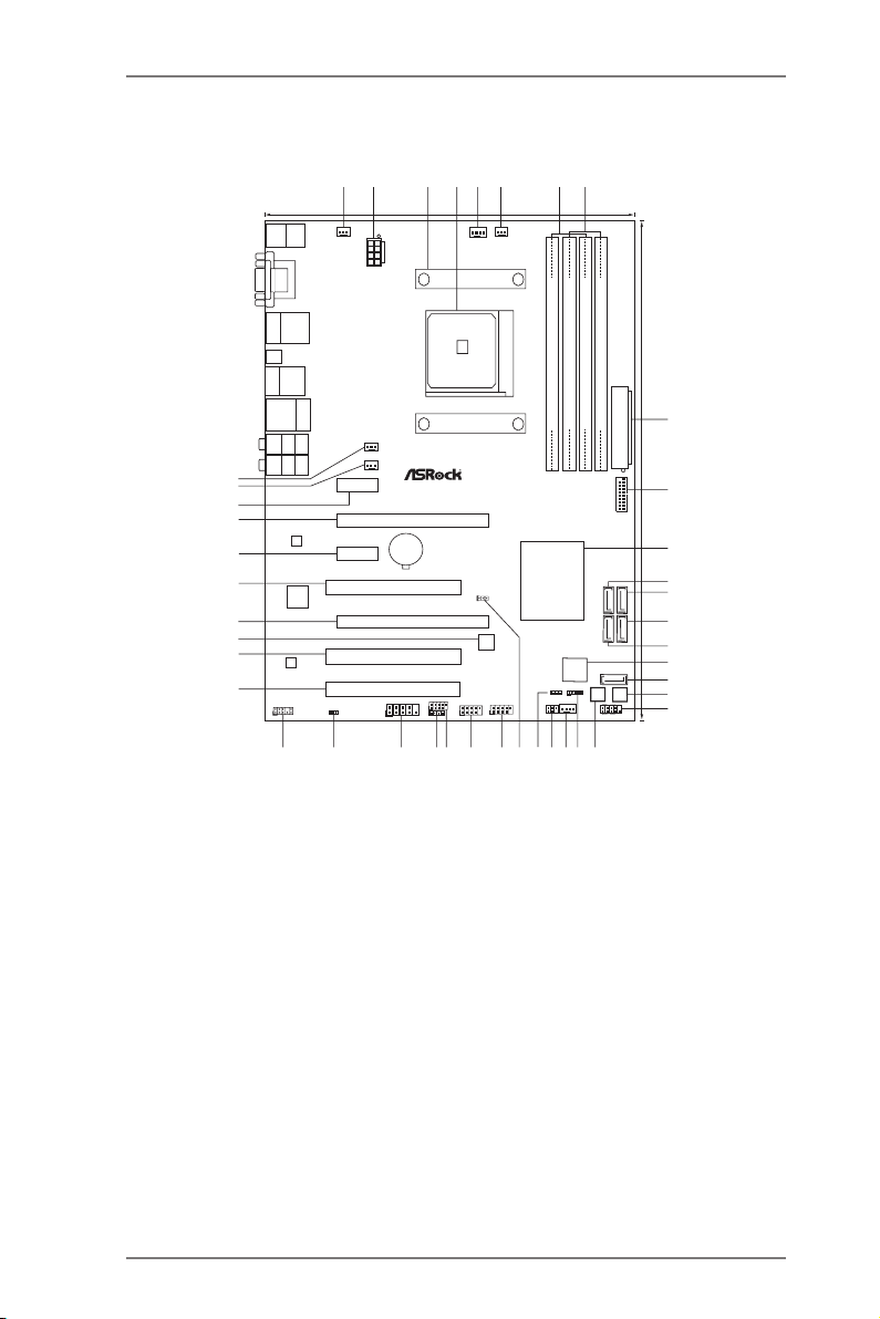
1.4 Motherboard Layout
ATXPW R1
AMD
A75 FC H
(Hu dso n-D 3)
Chi pse t
PCIE1
PCI1
LAN
AUDIO
CODEC
CPU_FAN1
30.5 cm (1 2.0 -in)
22.4 cm (8 .8- in)
64Mb
BIOS
PCIE2
CPU_FAN2
FM2 A7 5 P ro4
DDR 3 2 600 +
ATX12V1
SO CK ET FM 2
PCIE4
Dr.
Debug
DDR3_ A1 (6 4 bit, 240- pin mo dule )
DDR3_ A2 (6 4 bit, 240- pin mo dule )
DDR3_ B1 (6 4 bit, 240- pin mo dule )
DDR3_ B2 (6 4 bit, 240- pin mo dule )
PWR_FAN1
CHA_FAN3
CHA_FAN2
PCIE3
PCI2
PCI3
Dual Gr aphi cs
1
CLRCMOS1
PWRBTN
RSTBTN
HDLED RESET
PLEDP WRBTN
1
PANEL1
SATA3_5
SATA3_4 SATA3_2
SATA3_3
SATA3_1
IR1
1
CHA_FAN1
SPEAKER1
1
PLED1
1
HD_AUDIO1
1
1
HDMI_SPDIF1
COM1
1
1
USB3_4
CIR1
1
1
USB5_6
1
USB7_8
Top:
CTR BASS
Center:
REAR SPK
Bottom:
Optical
SPDIF
Top:
LINE IN
Center:
FRONT
Bottom:
MIC IN
Top:
RJ-45
USB3. 0
T:USB1
B:USB 2
Ps2
Keyboar d/
Mouse
VGA1
DVI1
USB 3.0
T:US B3
B: USB4
HDMI 1
Clr
CMOS
USB 2.0
T:US B1
B: USB2
eSATA1
USB 3.0
T:US B5
B: USB6
USB3_7_8
X
Fast USB
X
Fast RAM
X
Fast LAN
RoHS
ErP/ EuP Read y
DX11
Fron t U SB 3 .0
6
7
1
2
4
3
5
8
9
10
11
12
13
14
15
16
17
18
19
20
21
22
23242526
27
2829
30
31
32
33
34
35
36
37
38
39
40
41
42
CMOS
BATTE R Y
Super
I/O
14
1 Power Fan Connector (PWR_FAN1) 21 Chassis Speaker Header (SPEAKER1)
2 ATX 12V Power Connector (ATX12V1) 22 Chassis Fan Connector (CHA_FAN1)
3 CPU Heatsink Retention Module 23 Infrared Module Header (IR1)
4 CPU Socket 24 Power LED Header (PLED1)
5 CPU Fan Connector (CPU_FAN1) 25 Clear CMOS Jumper (CLRCMOS1)
6 CPU Fan Connector (CPU_FAN2) 26 USB 2.0 Header (USB7_8)
7 2 x 240-pin DDR3 DIMM Slots 27 USB 2.0 Header (USB5_6)
(Dual Channel A: DDR3_A1, DDR3_B1) 28 USB 2.0 Header (USB3_4)
8 2 x 240-pin DDR3 DIMM Slots 29 Consumer Infrared Module Header (CIR1)
(Dual Channel B: DDR3_A2, DDR3_B2) 30 COM Port Header (COM1)
9 ATX Power Connector (ATXPWR1) 31 HDMI_SPDIF Header (HDMI_SPDIF1)
10 USB 3.0 Header (USB3_7_8) 32 Front Panel Audio Header (HD_AUDIO1)
11 Southbridge Controller 33 PCI Slot (PCI3)
12 SATA3 Connector (SATA3_2) 34 PCI Slot (PCI2)
13 SATA3 Connector (SATA3_1) 35 SPI Flash Memory (64Mb)
14 SATA3 Connector (SATA3_3) 36 PCI Express 2.0 x16 Slot (PCIE4)
15 SATA3 Connector (SATA3_4) 37 PCI Slot (PCI1)
16 Dr. Debug (LED) 38 PCI Express 2.0 x1 Slot (PCIE3)
17 SATA3 Connector (SATA3_5) 39 PCI Express 2.0 x16 Slot (PCIE2)
18 Reset Switch (RSTBTN) 40 PCI Express 2.0 x1 Slot (PCIE1)
19 System Panel Header (PANEL1) 41 Chassis Fan Connector (CHA_FAN2)
20 Power Switch (PWRBTN) 42 Chassis Fan Connector (CHA_FAN3)
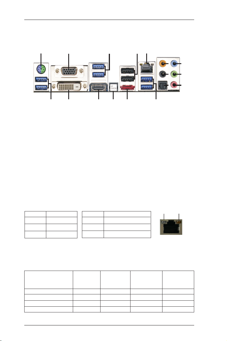
1.5 I/O Panel
5
4
9
6
10
7
11
8
12
ACT/LINK
LED
SPEED
LED
15
3
13
14
1
17
1 PS/2 Mouse/Keyboard Port (Green/Purple) *** 10 Front Speaker (Lime)
2 D-Sub Port (VGA1) 11 Microphone (Pink)
3 Etron USB 3.0 Ports (USB34) 12 Etron USB 3.0 Ports (USB56)
* 4 USB 2.0 Ports (USB01) **** 13 eSATA3 Connector (eSATA1)
** 5 LAN RJ-45 Port 14 Clear CMOS Switch (CLRCBTN)
6 Central / Bass (Orange) 15 HDMI Port (HDMI1)
7 Rear Speaker (Black) 16 DVI-D Port (DVI1)
8 Optical SPDIF Out Port 17 AMD USB 3.0 Ports (USB12)
9 Line In (Light Blue)
* It is recommended to install the USB Keyboard/Mouse cable to USB 2.0 ports (USB01)
instead of USB 3.0 ports.
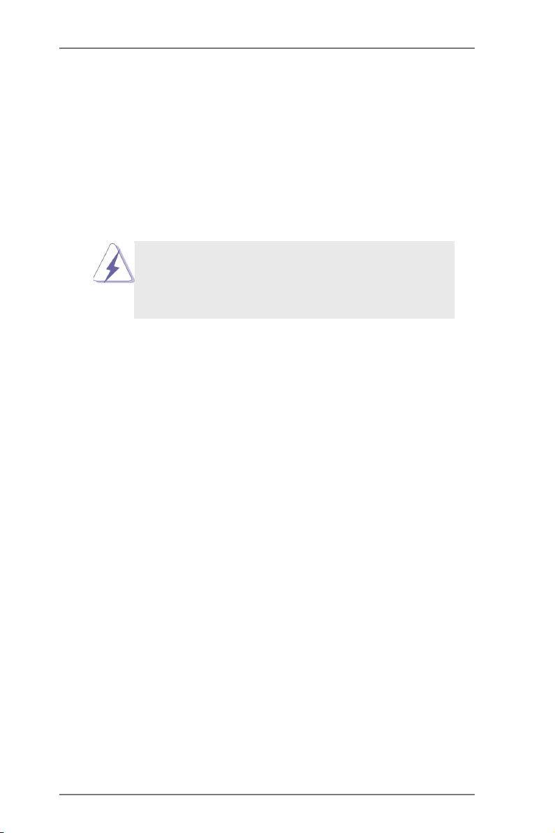
** There are two LED next to the LAN port. Please refer to the table below for the LAN port LED
indications.
Activity/Link LED SPEED LED
Status Description Status Description
2
16
LAN Port LED Indications
Off No Link Off 10Mbps connection
Blinking Data Activity Orange 100Mbps connection
On Link Green 1Gbps connection
LAN Port
If you use 2-channel speaker, please connect the speaker’s plug into “Front Speaker Jack”.
***
See the table below for connection details in accordance with the type of speaker you use.
TABLE for Audio Output Connection
Audio Output Channels Front Speaker Rear Speaker Central / Bass Line In or
(No. 10) (No. 7) (No. 6) Side Speaker
(No. 9)
2 V -- -- --
4 V V -- --
6 V V V --
8 V V V V
15

To enable Multi-Streaming function, you need to connect a front panel audio cable to the front
panel audio header. After restarting your computer, you will nd “Mixer” tool on your system.
Please select “Mixer ToolBox” , click “Enable playback multi-streaming”, and click “ok”.
Choose “2CH”, “4CH”, “6CH”, or “8CH” and then you are allowed to select “Realtek HDA Pri-
mary output” to use Rear Speaker, Central/Bass, and Front Speaker, or select “Realtek HDA
Audio 2nd output” to use front panel audio.
**** eSATA3 connector supports SATA Gen3 in cable 1M.
16
2. Installation
This is an ATX form factor (12.0-in x 8.8-in, 30.5 cm x 22.4 cm) motherboard.
Before you install the motherboard, study the conguration of your chassis to ensure
that the motherboard ts into it.
Pre-installation Precautions
Take note of the following precautions before you install motherboard
components or change any motherboard settings.
Before you install or remove any component, ensure that the
power is switched off or the power cord is detached from the
power supply. Failure to do so may cause severe damage to the
motherboard, peripherals, and/or components.
1. Unplug the power cord from the wall socket before touching any
component.
2. To avoid damaging the motherboard components due to static elec-
tricity, NEVER place your motherboard directly on the carpet or the
like. Also remember to use a grounded wrist strap or touch a safety
grounded object before you handle components.
3. Hold components by the edges and do not touch the ICs.
4. Whenever you uninstall any component, place it on a grounded anti-
static pad or in the bag that comes with the component.
5. When placing screws into the screw holes to secure the mother-
board to the chassis, please do not over-tighten the screws! Doing
so may damage the motherboard.
17
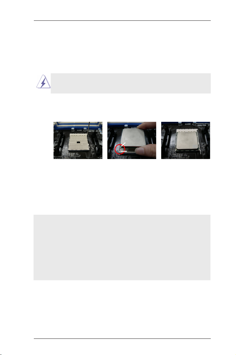
2.1 CPU Installation
Step 1. Unlock the socket by lifting the lever up to a 90
o
angle.
Step 2. Position the CPU directly above the socket such that the CPU corner with
the golden triangle matches the socket corner with a small triangle.
Step 3. Carefully insert the CPU into the socket until it ts in place.
The CPU ts only in one correct orientation. DO NOT force the CPU
into the socket to avoid bending of the pins.
Step 4. When the CPU is in place, press it rmly on the socket while you push
down the socket lever to secure the CPU. The lever clicks on the side tab
to indicate that it is locked.
Lever 90° Up
CPU Golden Triangle
STEP 1:
Lift Up The Socket Lever
STEP 2 / STEP 3:
Match The CPU Golden Triangle
To The Socket Corner Small
Triangle
Socket Corner Small
Triangle
STEP 4:
Push Down And Lock
The Socket Lever
2.2 Installation of CPU Fan and Heatsink
After you install the CPU into this motherboard, it is necessary to install a
larger heatsink and cooling fan to dissipate heat. You also need to spray
thermal grease between the CPU and the heatsink to improve heat dis-
sipation. Make sure that the CPU and the heatsink are securely fastened
and in good contact with each other. Then connect the CPU fan to the
CPU FAN connector (CPU_FAN1, see Page 14, No. 5 or CPU_FAN2,
see Page 14, No. 6). For proper installation, please kindly refer to the
instruction manuals of the CPU fan and the heatsink.
18
2.3 Installation of Memory Modules (DIMM)
This motherboard provides four 240-pin DDR3 (Double Data Rate 3) DIMM
slots, and supports Dual Channel Memory Technology. For dual channel con-
guration, you always need to install identical (the same brand, speed, size
and chip-type) DDR3 DIMM pair in the slots of the same color. In other words,
you have to install identical DDR3 DIMM pair in Dual Channel A (DDR3_A1
and DDR3_B1; see p.14 No.7) or identical DDR3 DIMM pair in Dual Channel
B (DDR3_A2 and DDR3_B2; see p.14 No.8), so that Dual Channel Memory
Technology can be activated. This motherboard also allows you to install four
DDR3 DIMMs for dual channel conguration, and please install identical DDR3
DIMMs in all four slots. You may refer to the Dual Channel Memory Congura-
tion Table below.
Dual Channel Memory Congurations
DDR3_A1 DDR3_A2 DDR3_B1 DDR3_B2
(1) Populated - Populated -
(2) - Populated - Populated
(3)* Populated Populated Populated Populated
For the conguration (3), please install identical DDR3 DIMMs in all four
*
slots.
1. If you want to install two memory modules, for optimal compatibility
and reliability, it is recommended to install them in the slots: DDR3_
A1 and DDR3_B1, or DDR3_A2 and DDR3_B2.
2. If only one memory module or three memory modules are installed
in the DDR3 DIMM slots on this motherboard, it is unable to activate
the Dual Channel Memory Technology.
3. If a pair of memory modules is NOT installed in the same Dual
Cha nn el , for examp le , installi ng a p ai r of me mo ry modules in
DDR3_A1 and DDR3_A2, it is unable to activate the Dual Channel
Memory Technology .
4. It is not allowed to install a DDR or DDR2 memory module into
DDR3 slot; otherwise, this motherboard and DIMM may be dam-
aged.
5. If you adopt DDR3 2600/2400/2133/1866/1600 memory modules
on this motherboard, it is recommended to install them on DDR3_
A2 and DDR3_B2 slots.
19
Installing a DIMM
Please make sure to disconnect power supply before adding or
removing DIMMs or the system components.
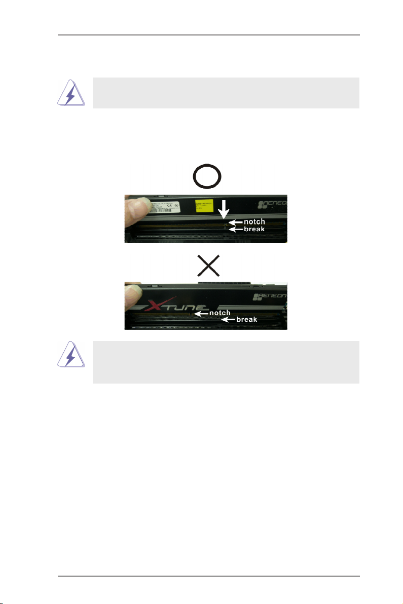
Step 1. Unlock a DIMM slot by pressing the retaining clips outward.
Step 2. Align a DIMM on the slot such that the notch on the DIMM matches the
break on the slot.
The DIMM only ts in one correct orientation. It will cause permanent
damage to the motherboard and the DIMM if you force the DIMM into
the slot at incorrect orientation.
Step 3. Firmly insert the DIMM into the slot until the retaining clips at both ends
fully snap back in place and the DIMM is properly seated.
20
2.4 Expansion Slots (PCI and PCI Express Slots)
There are 3 PCI slots and 4 PCI Express slots on this motherboard.
PCI Slots: PCI slots are used to install expansion cards that have the 32-bit PCI
interface.
PCIE Slots:
PCIE1 / PCIE3 (PCIE x1 slot) is used for PCI Express cards with x1
lane width cards, such as Gigabit LAN card and SATA2 card.
PCIE2 (PCIE x16 slot) is used for PCI Express x16 lane width graphics
cards, or used to install PCI Express graphics cards to support CrossFi-
reXTM function.
PCIE4 (PCIE x16 slot) is used for PCI Express x4 lane width cards,
or used to install PCI Express graphics cards to support CrossFireXTM
function.
1. In single VGA card mode, it is recommended to install a PCI Ex-
press x16 graphics card on PCIE2 slot.
2. In CrossFireXTM mode, please install PCI Express x16 graphics
cards on PCIE2 and PCIE4 slots.
3. Please connect a chassis fan to motherboard chassis fan connec-
tor (CHA_FAN1, CHA_FAN2 or CHA_FAN3) when using multiple
graphics cards for better thermal environment.
Installing an expansion card
Step 1. Before installing the expansion card, please make sure that the power
supply is switched off or the power cord is unplugged. Please read the
documentation of the expansion card and make necessary hardware
settings for the card before you start the installation.
Step 2. Remove the system unit cover (if your motherboard is already installed
in a chassis).
Step 3. Remove the bracket facing the slot that you intend to use. Keep the
screws for later use.
Step 4. Align the card connector with the slot and press rmly until the card is
completely seated on the slot.
Step 5. Fasten the card to the chassis with screws.
Step 6. Replace the system cover.
21
2.5 CrossFireXTM and Quad CrossFireXTM Operation Guide
Th i s mo t herb o ard sup p orts Cro s sFir e XTM a nd Q uad C ross F ireXTM f eatu re.
CrossFi reXTM tec hno log y offe rs t he most ad van tag eou s me ans avail abl e of
combining multiple high performance Graphics Processing Units (GPU) in a single
PC. Combining a range of different operating modes with intelligent software design
and an innovative interconnect mechanism, CrossFireXTM enables the highest
possible level of performance and image quality in any 3D application. Currently
CrossFireXTM feature is supported with Windows® VistaTM / 7 OS. Quad CrossFireX
TM
feature are supported with Windows® VistaTM / 7 OS only. Please check AMD
website for AMD CrossFireXTM driver updates.
1. If a c us tomer incorre ct ly confi gu re s thei r s ys te m they will not see t he
performance benets of CrossFireXTM. All three CrossFireXTM components, a
CrossFireXTM Ready graphics card, a CrossFireXTM Ready motherboard and a
CrossFireXTM Edition co-processor graphics card, must be installed correctly
to benet from the CrossFireXTM multi-GPU platform.
2. If you pair a 12-pipe CrossFireXTM Edition card with a 16-pipe card, both
cards will operate as 12-pipe cards while in CrossFireXTM mode.
2.5.1 Graphics Card Setup
Different CrossFireXTM cards may require different methods to enable CrossFi-
reXTM feature. For other CrossFireXTM cards that AMD has released or will release
in the future, please refer to AMD graphics card manuals for detailed installation
guide.
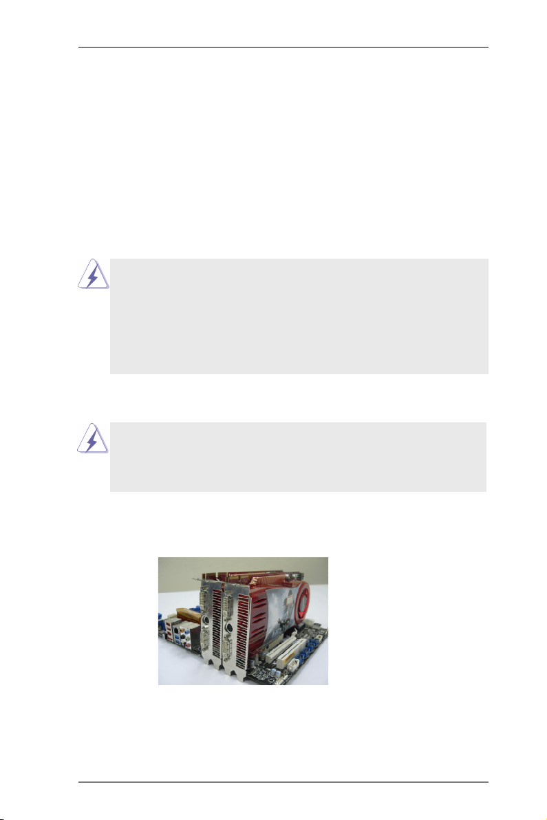
Step 1. Insert one Radeon graphics card into PCIE2 slot and the other Radeon
graphics card to PCIE4 slot. Make sure that the cards are properly seated
on the slots.
22
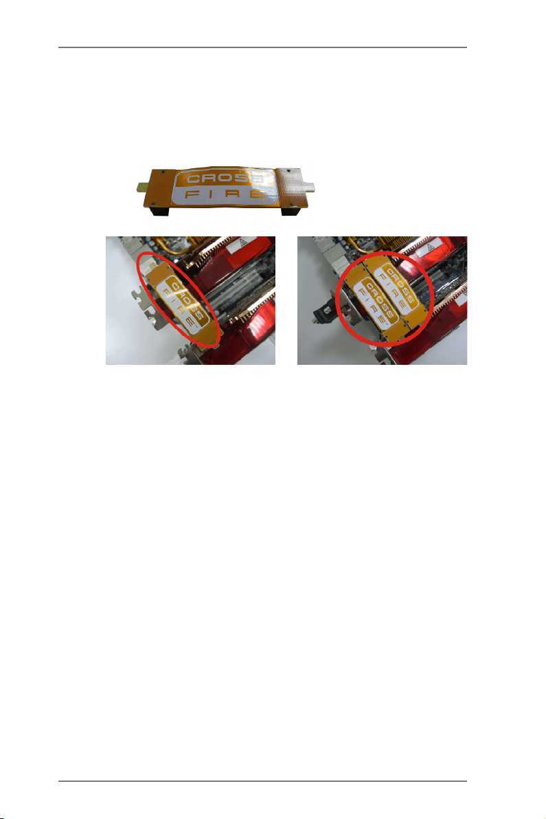
Step 2. Connect two Radeon graphics cards by installing CrossFire Bridge on
CrossFire Bridge Interconnects on the top of Radeon graphics cards.
(CrossFire Bridge is provided with the graphics card you purchase, not
bundled with this motherboard. Please refer to your graphics card vendor
for details.)
CrossFire Bridge
or
Step 3. Connect the DVI monitor cable to the DVI connector on the Radeon graph-
ics card on PCIE2 slot. (You may use the DVI to D-Sub adapter to convert
the DVI connector to D-Sub interface, and then connect the D-Sub monitor
cable to the DVI to D-Sub adapter.)
23
2.5.2 Driver Installation and Setup
Step 1. Power on your computer and boot into OS.
Step 2. Remove the AMD driver if you have any VGA driver installed in your sys-
tem.
The Catalyst Uninstaller is an optional download. We recommend using this
utility to uninstall any previously installed Catalyst drivers prior to installation.
Please check AMD website for AMD driver updates.
Step 3. Install the required drivers to your system.
For Windows® 7 / VistaTM OS:
Install the CATALYST Control Center. Please check AMD website for de-
tails.
Step 4. Restart your computer.
Step 5. Install the VGA card drivers to your system, and restart your computer.
Then you will nd “ATI Catalyst Control Center” on your Windows® taskbar.
ATI Catalyst Control Center
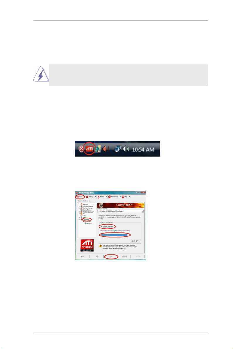
Step 6. Double-click “ATI Catalyst Control Center”. Click “View”, select “CrossFi-
reXTM”, and then check the item “Enable CrossFireXTM”. Select “2 GPUs”
and click “Apply” (if you install two Radeon graphics cards).
24

Although you have selected the option “Enable CrossFireTM”, the Cross-
FireXTM function may not work actually. Your computer will automatically
reboot. After restarting your computer, please conrm whether the option
“Enable CrossFireTM” in “ATI Catalyst Control Center” is selected or not;
if not, please select it again, and then you are able to enjoy the benet of
CrossFireX
TM
feature.
Step 7. You can freely enjoy the benet of CrossFireXTM or Quad CrossFireXTM
feature.
* CrossFireXTM appearing here is a registered trademark of AMD Technologies Inc., and is
used only for identication or explanation and to the owners’ benet, without intent to infringe.
* For further information of AMD CrossFireXTM technology, please check AMD website for
updates and details.
25
 Loading...