

ASRock Fatal1ty Z370 Professional Gaming i7 Service Manual

Z370 Professional Gaming i7
User Manual
Version 1.0
Published December 2016
Copyright©2016 ASRock INC. All rights reserved.

Version 1.0
Published August 2017
Copyright©2017 ASRock INC. All rights reserved.
Copyright Notice:
No part of this documentation may be reproduced, transcribed, transmitted, or
translated in any language, in any form or by any means, except duplication of
documentation by the purchaser for backup purpose, without written consent of
ASRock Inc.
Products and corporate names appearing in this documentation may or may not
be registered trademarks or copyrights of their respective companies, and are used
only for identication or explanation and to the owners’ benet, without intent to
infringe.
Disclaimer:
Specications and information contained in this documentation are furnished for
informational use only and subject to change without notice, and should not be
constructed as a commitment by ASRock. ASRock assumes no responsibility for
any errors or omissions that may appear in this documentation.
With respect to the contents of this documentation, ASRock does not provide
warranty of any kind, either expressed or implied, including but not limited to
the implied warranties or conditions of merchantability or tness for a particular
purpose.
In no event shall ASRock, its directors, ocers, employees, or agents be liable for
any indirect, special, incidental, or consequential damages (including damages for
loss of prots, loss of business, loss of data, interruption of business and the like),
even if ASRock has been advised of the possibility of such damages arising from any
defect or error in the documentation or product.
is device complies with Part 15 of the FCC Rules. Operation is subject to the following
two conditions:
(1) this device may not cause harmful interference, and
(2) this device must accept any interference received, including interference that
may cause undesired operation.
CALIFORNIA, USA ONLY
e Lithium battery adopted on this motherboard contains Perchlorate, a toxic substance
controlled in Perchlorate Best Management Practices (BMP) regulations passed by the
California Legislature. When you discard the Lithium battery in California, USA, please
follow the related regulations in advance.
“Perchlorate Material-special handling may apply, see ww w.dtsc.ca.gov/hazardouswaste/
perchlorate”
ASRock Website: http://www.asrock.com

AUSTRALIA ONLY
Our goods come with guarantees that cannot be excluded under the Australian Consumer
Law. You are entitled to a replacement or refund for a major failure and compensation for
any other reasonably foreseeable loss or damage caused by our goods. You are also entitled
to have the goods repaired or replaced if the goods fail to be of acceptable quality and the
failure does not amount to a major failure. If you require assistance please call ASRock Tel
: +886-2-28965588 ext.123 (Standard International call charges apply)
e terms HDMI™ and HDMI High-Denition Multimedia Interface, and the HDMI
logo are trademarks or registered trademarks of HDMI Licensing LLC in the United
States and other countries.
CE Warning
is device complies with directive 2014/53/EU issued by the Commision of the European
Community.
is equipment complies with EU radiation exposure limits set forth for an uncontrolled
environment.
is equipment should be installed and operated with minimum distance 20cm between
the radiator & your body.
Operations in the 5.15-5.35GHz band are restricted to indoor usage only.
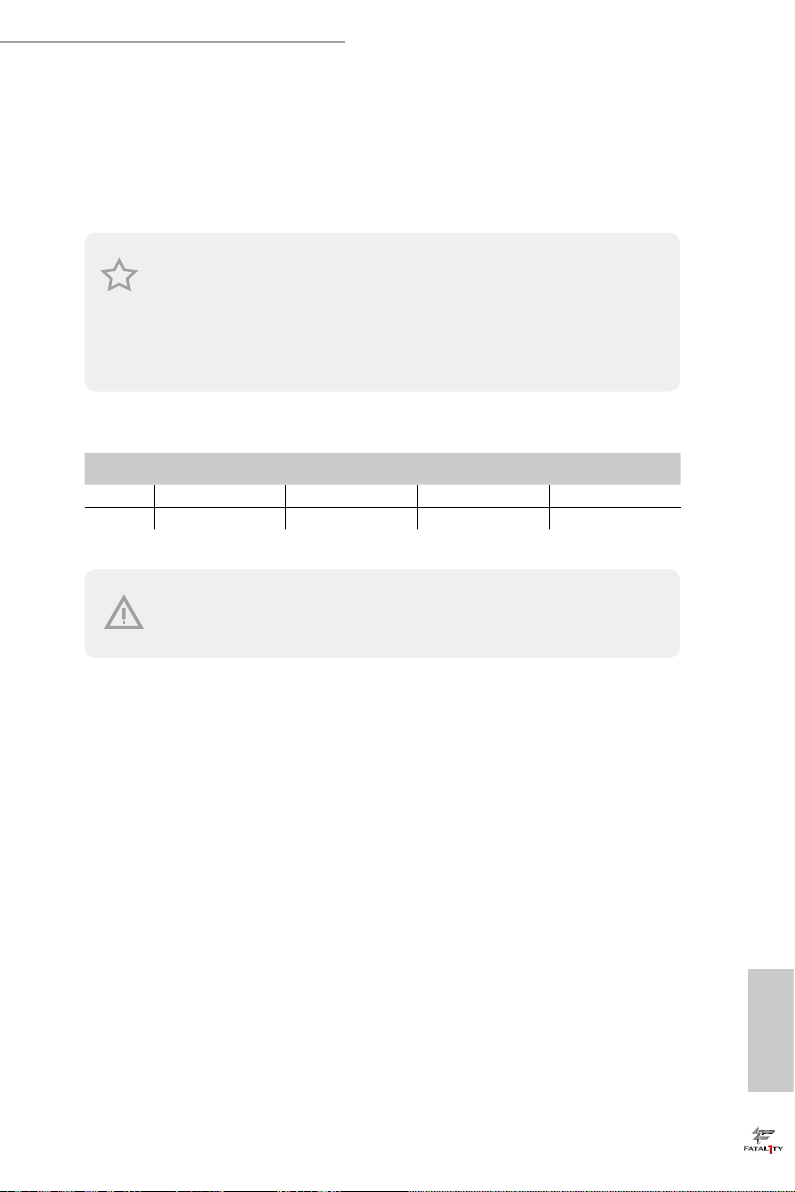
Radio transmit power per transceiver ty pe
Function Frequency Maximum Output Power (EIRP)
2400-2483.5 MHz 18.5 + / -1.5 dbm
5150-5250 MHz 21.5 + / -1.5 dbm
WiFi
Bluetooth 2400-2483.5 MHz 8.5 + / -1.5 dbm
5250-5350 MHz
5470-5725 MHz
18.5 + / -1.5 dbm (no TPC)
21.5 + / -1.5 dbm (TPC)
25.5 + / -1.5 dbm (no TPC)
28.5 + / -1.5 dbm (TPC)

Fatal1ty Story
Who knew that at age 19, I would be a World Champion PC gamer. When I was 13, I actually
played competitive billiards in professional tournaments and won four or ve games o guys
who played at the highest level. I actually thought of making a career of it, but at that young
age situations change rapidly. Because I’ve been blessed with great hand-eye coordination and
a grasp of mathematics (an important element in video gaming) I gravitated to that activity.
GOING PRO
I started professional gaming in 1999 when I entered the CPL (Cyberathlete Professional
League) tournament in Dallas and won $4,000 for coming in third place. Emerging as one
of the top players in the United States, a company interested in sponsoring me ew me to
Sweden to compete against the top 12 players in the world. I won 18 straight games, lost
none, and took rst place, becoming the number one ranked Quake III player in the world
in the process. Two months later I followed that success by traveling to Dallas and defending
my title as the world’s best Quake III player, winning the $40,000 grand prize. From there
I entered competitions all over the world, including Singapore, Korea, Germany, Australia,
Holland and Brazil in addition to Los Angeles, New York and St. Louis.
WINNING STREAK
I was excited to showcase my true gaming skills when defending my title as CPL
Champion of the year at the CPL Winter 2001 because I would be competing in a totally
dierent rst person shooter (fps) game, Alien vs. Predator II. I won that competition and
walked away with a new car. e next year I won the same title playing Unreal Tournament
2003, becoming the only three-time CPL champion of the year. And I did it playing a
different game each year, something no one else has ever done and a feat of which I am
extremely proud.
At QuakeCon 2002, I faced o against my rival ZeRo4 in one of the most highly
anticipated matches of the year, winning in a 14 to (-1) killer victory. Competing at Quakecon
2004, I became the World’s 1st Doom3 Champion by defeating Daler in a series of very
challenging matches and earning $25,000 for the victory.
Since then Fatal1ty has traveled the globe to compete against the best in the world, winning
prizes and acclaim, including the 2005 CPL World Tour Championship in New York City for
a $150,000 rst place triumph. In August 2007, Johnathan was awarded the rst ever Lifetime
Achievement Award in the four year history of the eSports-Award for “showing exceptional
sportsmanship, taking part in shaping eSports into what it is today and for being the prime
representative of this young sport. He has become the gurehead for eSports worldwide”.

LIVIN’ LARGE
Since my rst big tournament wins, I have been a “Professional Cyberathlete”, traveling the
world and livin’ large with lots of International media coverage on outlets such as MTV,
ESPN and a 60 Minutes segment on CBS to name only a few. It's unreal - it's crazy. I’m living
a dream by playing video games for a living. I’ve always been athletic and took sports like
hockey and football very seriously, working out and training hard. is discipline helps me
become a better gamer and my drive to be the best has opened the doors necessary to become
a professional.
A DREAM
Now, another dream is being realized – building the ultimate gaming computer, made
up of the best parts under my own brand. Quality hardware makes a huge difference in
competitions…a couple more frames per second and everything gets really nice. It’s all about
getting the computer processing faster and allowing more uid movement around the maps.
My vision for Fatal1ty hardware is to allow gamers to focus on the game without worrying
about their equipment, something I’ve preached since I began competing. I don’t want to
worry about my equipment. I want to be there – over and done with - so I can focus on
the game. I want it to be the fastest and most stable computer equipment on the face of the
planet, so quality is what Fatal1ty Brand products represent.
Johnathan “Fatal1ty” Wendel
e Fatal1ty name, Fatal1ty logos and the Fatal1ty likeness are registered trademarks of Fatal1ty, Inc., and are used
under license. © 2016 Fatal1ty, Inc. All rights reserved. All other trademarks are the property of their respective
owners.

Contents
Chapter 1 Introduction 1
1.1 Package Contents 1
1.2 Specications 2
1.3 Motherboard Layout 8
1.4 I/O Panel 10
1.5 WiFi-802.11ac Module and ASRock WiFi 2.4/5 GHz Antenna 12
Chapter 2 Installation 14
2.1 Installing the CPU 15
2.2 Installing the CPU Fan and Heatsink 18
2.3 Installing Memory Modules (DIMM) 19
2.4 Expansion Slots (PCI and PCI Express Slots) 21
2.6 Onboard Headers and Connectors 23
2.7 Smart Switches 29
2.8 Dr. Debug 30
2.9 SLITM and Quad SLITM Operation Guide 32
2.9.1 Installing Two SLITM-Ready Graphics Cards 32
2.9.2 Driver Installation and Setup 34
2.10 CrossFireXTM , 3-Way CrossFireXTM and Quad CrossFireXTM
Operation Guide 35
2.10.1 Installing Two CrossFireXTM-Ready Graphics Cards 35
2.10.2 Installing Three CrossFireXTM-Ready Graphics Cards 37
2.10.3 Driver Installation and Setup 38

Chapter 3 Software and Utilities Operation 47
3.1 Installing Drivers 47
3.2 F-Stream 48
3.3 ASRock Live Update & APP Shop 51
3.3.1 UI Overview 51
3.3.2 Apps 52
3.3.3 BIOS & Drivers 55
3.3.4 Setting 56
3.4 Creative SoundBlaster Cinema3 57
3.5 ASRock RGB LED 58
Chapter 4 UEFI SETUP UTILITY 60
4.1 Introduction 60
4.2 EZ Mode 61
4.3 Advanced Mode 62
4.3.1 UEFI Menu Bar 62
4.3.2 Navigation Keys 63
4.4 Main Screen 64
4.5 OC Tweaker Screen 65
4.6 Advanced Screen 77
4.6.1 CPU Conguration 78
4.6.2 Chipset Conguration 80
4.6.3 Storage Conguration 83
4.6.4 Intel® Thunderbolt 85
4.6.5 Super IO Conguration 86

4.6.6 ACPI Conguration 87
4.6.7 USB Conguration 88
4.6.8 Trusted Computing 89
4.7 Tools 90
4.8 Hardware Health Event Monitoring Screen 93
4.9 Security Screen 96
4.10 Boot Screen 97
4.11 Exit Screen 100

Fatal1ty Z370 Professional Gaming i7 Series
Chapter 1 Introduction
ank you for purchasing ASRock Fatal1ty Z370 Professional Gaming i7 Series
motherboard, a reliable motherboard produced under ASRock’s consistently
stringent quality control. It delivers excellent performance with robust design
conforming to ASRock’s commitment to quality and endurance.
In this documentation, Chapter 1 and 2 contains the introduction of the
motherboard and step-by-step installation guides. Chapter 3 contains the operation
guide of the soware and utilities. Chapter 4 contains the conguration guide of
the BIOS setup.
Becau se the motherboard specications and the BIOS soware might be updated, the
content of this documentation will be subject to change without notice. In case any modications of this documentation occur, the updated version will be available on ASRock’s
website w ithout further notice. If you require technical support related to this motherboard, please visit our website for specic information about the model you are using. You
may nd the l atest VGA cards and CPU suppor t list on ASRock’s website a s well. ASRock
website http://www.asrock.com.
1.1 Package Contents
• ASRock Fatal1ty Z370 Professional Gaming i7 Series Motherboard (ATX Form Factor)
• ASRock Fatal1ty Z370 Professional Gaming i7 Series Quick Installation Guide
• ASRock Fatal1ty Z370 Professional Gaming i7 Series Support CD
• 4 x Serial ATA (SATA) Data Cables (Optional)
• 1 x ASRock SLI_HB_Bridge_2S Card (O pt iona l)
• 2 x ASRock WiFi 2.4/5 GHz Antennas (Opt iona l)
• 1 x I/O Panel Shield
• 3 x Screws for M.2 Sockets (Optional)
English
1

1.2 Specications
Platform
CPU
Chipset
Memory
• ATX Form Factor
• Supports 8th Generation Intel® CoreTM Processors (Socket
1151)
• Digi Power design
• 12 Power Phase design
• Supports Intel® Turbo Boost 2.0 Technology
• Supports Intel® K-Series unlocked CPUs
• Supports ASRock BCLK Full-range Overclocking
• Supports ASRock Hyper BCLK Engine II
• Intel® Z370
• Dual Channel DDR4 Memory Technology
• 4 x DDR4 DIMM Slots
• Supports DDR4 4333+(OC)*/4266(OC)/4133(OC)/4000(OC)
/3866(OC)/3800(OC)/3733(OC)/3600(OC)/3200(OC)/2933
(OC)/2800(OC)/2666/2400/2133 non-ECC, un-buered
memory
* Please refer to Memory Support List on ASRock's website for
more information. (http://www.asrock.com/)
* 8th Gen Intel® CPU supports DDR4 up to 2666.
• Supports ECC UDIMM memory modules (operate in non-
ECC mode)
• Max. capacity of system memory: 64GB
• Supports Intel® Extreme Memory Prole (XMP) 2.0
• 15μ Gold Contact in DIMM Slots
English
2
Expansion
Slot
• 3 x PCI Express 3.0 x16 Slots (PCIE2/PCIE4/PCIE5: single
at x16 (PCIE2); dual at x8 (PCIE2) / x8 (PCIE4); triple at x8
(PCIE2) / x4 (PCIE4) / x4 (PCIE5))*
* Supports NVMe SSD as boot disks
• 2 x PCI Express 3.0 x1 Slots (Flexible PCIe)
• Supports AMD Quad CrossFireXTM, 3-Way CrossFireXTM
and CrossFireXTM
• Supports NVIDIA® Quad SLITM and SLI
TM

Fatal1ty Z370 Professional Gaming i7 Series
• 1 x Vertical M.2 Socket (Key E) with the bundled WiFi-
802.11ac module (on the rear I/O)
• 15μ Gold Contact in VGA PCIe Slot (PCIE2)
Graphics
• Intel® UHD Graphics Built-in Visuals and the VGA outputs
can be supported only with processors which are GPU
integrated.
• Supports Intel® UHD Graphics Built-in Visuals : Intel®
Quick Sync Video with AVC, MVC (S3D) and MPEG-2 Full
HW Encode1, Intel® InTruTM 3D, Intel® Clear Video HD
Technology, Intel® InsiderTM, Intel® UHD Graphics
• DirectX 12
• HWAEncode/Decode: VP9 8-bit, VP9 10- bit (Encode only),
VP8, HEVC (MPEG-H Part2, h.265), AVC (MPEG4, h.264),
MPEG2-Part2 (h.262), JPEG/MJPEG,VC-1
• Max. shared memory 1024MB
* e size of ma ximum shared memory may vary from dierent
operating systems.
• Dual graphics output: Support HDMI and DisplayPort 1.2
ports by independent display controllers
• Supports HDMI with max. resolution up to 4K x 2K
(4096x2160) @ 30Hz
• Supports DisplayPort 1.2 with max. resolution up to 4K x 2K
(4096x2304) @ 60Hz
• Supports Auto Lip Sync, Deep Color (12bpc), xvYCC and
HBR (High Bit Rate Audio) with HDMI Port (Compliant
HDMI monitor is required)
• Supports HDCP with HDMI and DisplayPort 1.2 Ports
• Supports 4K Ultra HD (UHD) playback with HDMI and
DisplayPort 1.2 Ports
Audio
• 7.1 CH HD Audio with Content Protection (Realtek
ALC1220 Audio Codec)
• Premium Blu-ray Audio support
• Supports Surge Protection
• Nichicon Fine Gold Series Audio Caps
• 120dB SNR DAC with Dierential Amplier
English
3

• NE5532 Premium Headset Amplier for Front Panel Audio
Connector (Supports up to 600 Ohm headsets)
• Pure Power-In
• Direct Drive Technology
• PCB Isolate Shielding
• Impedance Sensing on Front Out port
• Individual PCB Layers for R/L Audio Channel
• RGB LED
• Gold Audio Jacks
• 15μ Gold Audio Connector
• Supports Creative SoundBlaster Cinema3
English
LAN
Wireless
LAN
Rear Panel
I/O
1 x 10 Gigabit LAN 100/1000/2500/5000/10000 Mb/s (AQUAN-
TI A® AQC107):
• Supports Wake-On-LAN
• Supports Lightning/ESD Protection
• Supports PXE
2 x Gigabit LAN 10/100/1000 Mb/s (1 x Intel® I219V, 1 x Intel®
I211AT):
• Supports Wake-On-LAN
• Supports Lightning/ESD Protection
• Supports Energy Ecient Ethernet 802.3az
• Supports PXE
• Intel® 802.11ac WiFi Module
• Supports IEEE 802.11a/b/g/n/ac
• Supports Dual-Band (2.4/5 GHz)
• Supports high speed wireless connections up to 433Mbps
• Supports Bluetooth 4.2 / 3.0 + High speed class II
• 2 x Antenna Ports
• 1 x PS/2 Mouse/Keyboard Port
• 1 x HDMI Port
• 1 x DisplayPort 1.2
• 1 x Optical SPDIF Out Port
• 1 x USB 3.1 Gen2 Type-A Port (10 Gb/s) (ASMedia ASM3142)
(Supports ESD Protection)
4

Fatal1ty Z370 Professional Gaming i7 Series
• 1 x USB 3.1 Gen2 Type-C Port (10 Gb/s) (ASMedia ASM3142)
(Supports ESD Protection)
• 4 x USB 3.1 Gen1 Ports (Intel® Z370) (Supports ESD
Protection)
* 1 x Fatal1ty Mouse Port (USB 3.1 Gen1) is included
* Ultra USB Power is supported on USB_3_4 ports.
* ACPI wake-up function is not supported on USB_3_4 ports.
• 3 x RJ-45 LAN Ports with LED (ACT/LINK LED and SPEED
LED)
• 1 x Clear CMOS Button
• HD Audio Jacks: Rear Speaker / Central / Bass / Line in /
Front Speaker / Microphone (Gold Audio Jacks)
Storage
• 6 x SATA3 6.0 Gb/s Connectors, support RAID (RAID 0,
RAID 1, RAID 5, RAID 10, Intel Rapid Storage Technology
15), NCQ, AHCI and Hot Plug*
• 2 x SATA3 6.0 Gb/s Connectors by ASMedia ASM1061,
support NCQ, AHCI and Hot Plug
* M2_1, SATA3_0 and SATA3_1 share lanes. If either one of
them is in use, the others will be disabled.
* M2_ 2, SATA3_4 and SATA3_5 share lanes. If either one of
them is in use, the others will be disabled.
* If M2_3 is occupied by a SATA-type M.2 device, SATA3_3
will be disabled.
• 2 x Ultra M.2 Sockets (M2_1 and M2 _2), support M Key
type 2242/2260/2280/22110 M.2 SATA3 6.0 Gb/s module
and M.2 PCI Express module up to Gen3 x4 (32 Gb/s)**
• 1 x Ultra M.2 Socket (M2_3), supports M Key type
2242/2260/2280 M.2 SATA3 6.0 Gb/s module and M.2 PCI
Express module up to Gen3 x4 (32 Gb/s)**
** Type 22110 M.2 module is supported with either M2_1 or
M2_2 socket.
** Supports Intel® OptaneTM Tech nolo gy
** Supports NVMe SSD as boot disks
** Supports ASRock U.2 Kit
English
5

English
Connector
• 1 x TPM Header
• 1 x Power LED and Speaker Header
• 1 x RGB LED Header
* Supports in total up to 12V/3A, 36W LED Strip
• 1 x CPU Fan Connector (4-pin)
* e CPU Fan Connector supports the CPU fan of ma ximum
1A (12W) fan power.
• 1 x CPU Optional/Water Pump Fan Connector (4-pin)
(Smart Fan Speed Control)
* e CPU Optional/Water Pump Fan supports the water cooler
fan of maximum 1.5A (18W) fan power.
• 2 x Chassis Fan Connectors (4-pin) (Smart Fan Speed
Control)
• 1 x Chassis Optional/Water Pump Fan Connector (4-pin)
(Smart Fan Speed Control)
* e Chassis Optiona l/Water Pump Fan supports the water
cooler fan of maximum 1.5A (18W) fan power.
* CPU_OPT/W_PUMP, CHA_FAN1, CHA_FAN2 and CHA_
FAN3/W_PUMP can auto detect if 3-pin or 4-pin fan is in use.
• 1 x 24 pin ATX Power Connector (Hi-Density Power
Connec tor)
• 1 x 8 pin 12V Power Connector (Hi-Density Power
Connec tor)
• 1 x Front Panel Audio Connector (15μ Gold Audio
Connec tor)
• 1 x underbolt AIC Connector (5-pin)
• 3 x USB 2.0 Headers (Support 6 USB 2.0 ports) (Intel® Z370)
(Supports ESD Protection)
• 2 x USB 3.1 Gen1 Headers (Support 4 USB 3.1 Gen1 ports)
(ASMedia ASM1074 hub) (Supports ESD Protection)
• 1 x Front Panel Type C USB 3.1 Gen2 Header (ASMedia
ASM314 2)
• 1 x Dr. Debug with LED
• 1 x Power Button with LED
• 1 x Reset Button with LED
• 1 x X MP Switch
• 1 x BIOS B Select Jumper
6

Fatal1ty Z370 Professional Gaming i7 Series
BIOS
Feature
Hardware
Monitor
OS
• 2 x AMI UEFI Legal BIOS with multilingual GUI support
(1 x Main BIOS and 1 x Backup BIOS)
• Supports Secure Backup UEFI Technology
• ACPI 6.0 Compliant wake up events
• SMBIOS 2.7 Support
• CPU Core/Cache, GT Core/Cache, DRAM, PCH 1.0V,
VCCIO, VCCST, VCCSA, VCCPLL, CPU Internal PLL, GT
PLL, Ring PLL, System Agent PLL, Memory Controller PLL
Voltage Multi-adjustment
• Temperature Sensing: CPU, CPU Optional/Water Pump,
Chassis, Chassis Optional/Water Pump Fans
• Fan Tachometer: CPU, CPU Optional/Water Pump, Chassis,
Chassis Optional/Water Pump Fans
• Quiet Fan (Auto adjust chassis fan speed by CPU tempera-
ture): CPU, CPU Optional/Water Pump, Chassis, Chassis
Optional/Water Pump Fans
• Fan Multi-Speed Control: CPU, CPU Optional/Water Pump,
Chassis, Chassis Optional/Water Pump Fans
• Voltage monitoring: +12V, +5V, +3.3V, CPU Vcore, DRAM,
VPPM, PCH 1.0V, VCCSA, VCCST
• Microso® Windows® 10 64-bit
Certications
* For detailed product information, please visit our website: http://www.asrock .com
Please realiz e that the re is a certain r isk involved with o verclocking, including adjusting
the setting in the BIOS, applying Untied Overclocking Technolog y, or using third-party
overclocking to ols. O verclocking may aect your system’s stability, or even c ause damage to
the components and devices of your system. It should be don e at your ow n risk and expense.
We are not responsibl e for possible damage caused by overclo cking.
• FCC, CE
• ErP/EuP ready (ErP/EuP ready power supply is required)
English
7
Intel
Z370
DDR 4_A2 (6 4 bit, 28 8-pin m odule )
DDR 4_A1 (6 4 bit, 28 8-pin m odule )
DDR 4_B2 (6 4 bit, 28 8-pin m odule )
DDR 4_B1 (6 4 bit, 28 8-pin m odule )
ATX12V1
ATXP WR 1
PCIE2
Top:
RJ-45
(I211AT)
USB 3.1 Gen1
T: USB3
B: USB4
Top:
Central/Bass
Center :
REAR SPK
Top:
LINE IN
Center :
FRONT
Bottom :
Optica l
SPDIF
Bottom :
MIC IN
PCIE4
HDLED RESET
PLED PWRBTN
PANEL1
1
1
SPK_PLED1
1
HD_AUDIO1
PCIE5
PCIE1
7
8
1201
22 21
23
1
24
19
28
CLRBTN1
1
5
4
27
17
USB 3.1 Ge n1
T: USB1
B: USB2
PS2
Keybo ard
/Mous e
CMOS
Battery
T B1
1
26
2
USB_5_ 6
1
18
CPU_FAN1
1
TPMS1
USB 3.1 Gen2
T: USB31_TA_1
B: USB31_TC_1
3
1
USB_7_ 8
25
CPU_OPT/
W_PUMP
M2_WIFI_1
HDMI _1
DISP LAYI_1
RJ-45
(I219V)
Dr.
Debug
XMP_O N1
BIOS_A1
BIOS_B1
BIOS_A_LED1
BIOS
ROM
BIOS_B_LED1
BIOS
ROM
RGB_LED1
1
CHA_FAN2
CHA_FAN1
6
9
10
11
LAN
LAN
Ultra M.2
PCIe Gen3x4
RoHS
ON
OFF
FATAL TY
1
RSTBTN1PWRBTN1
29
30
Top:
RJ-45
(AQC107)
F_USB31_TC_2
SATA3_2_3
SATA3_4_5
SATA3_A1_ A2
13
12
14
15
16
SATA3_0_1
CHA_FAN3/
W_PUMP
PCIE3
M2_3
M2_1
M2_2
CLRMOS1
1
LAN
AUDIO
CODEC
D_BIOS_TEST1
1
1
USB_13_14
USB_11_12
USB_9_10
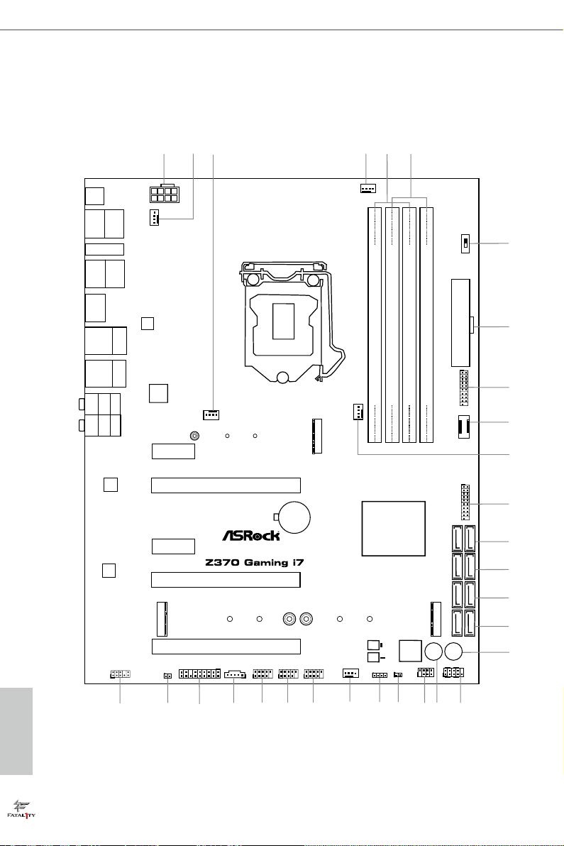
1.3 Motherboard Layout
English
8

Fatal1ty Z370 Professional Gaming i7 Series
No. Description
1 ATX 12V Power Connector (ATX12V1)
2 CPU Fan / Waterpump Fan Connector (CPU_OPT/W_PUMP)
3 Chassis Fan Connector (CHA_FAN1)
4 CPU Fan Connector (CPU_FAN1)
5 2 x 288-pin DDR4 DIMM Slots (DDR4_A1, DDR4_B1)
6 2 x 288-pin DDR4 DIMM Slots (DDR4_A2, DDR4_B2)
7 XMP Button (XMP_ON1)
8 ATX Power Connector (ATXPWR1)
9 USB 3.1 Gen1 Header (USB_5_6)
10 Front Panel Type C USB 3.1 Gen2 Header (F_USB31_TC_2)
11 Chassis Fan Connector (CHA_FAN2)
12 USB 3.1 Gen1 Header (USB_7_8)
13 SATA3 Connectors (SATA3_0_1)
14 SATA3 Connectors (SATA3_2_3)
15 SATA3 Connectors (SATA3_4_5)
16 SATA3 Connectors (SATA3_A1_A2)
17 Power Button (PW RBTN1)
18 System Panel Header (PANEL1)
19 Reset Button (RSTBTN1)
20 Power LED and Speaker Header (SPK_PLED1)
21 BIOS B Select Jumper (D_BIOS_TEST1)
22 RGB LED Header (RGB_LED1)
23 Chassis Fan / Waterpump Fan Connector (CHA_FAN3/W_PUMP)
24 USB 2.0 Header (USB_13_14)
25 USB 2.0 Header (USB_11_12)
26 USB 2.0 Header (USB_9_10)
27 underbolt AIC Header (TB1)
28 TPM Header (TPMS1)
29 Clear CMOS Jumper (CLRMOS1)
30 Front Panel Audio Header (HD_AUDIO1)
English
9
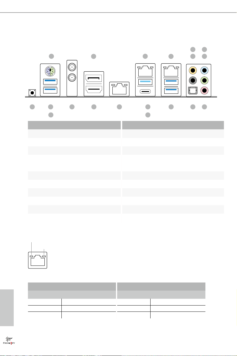
1.4 I/O Panel
1
7
2
3
4
658
17 11141519
18
16
13
91012
No. Description No. Description
1 PS/2 Mouse/Keyboard Port 11 USB 3.1 Gen1 Ports (USB_3_4) ****
2 DisplayPort 1.2 12 USB 3.1 Gen2 Type-A Port (USB31_TA_1)
3 LAN RJ-45 Port (Intel® I211AT)* 13 USB 3.1 Gen2 Type-C Port (USB31_TC_1)
GLAN RJ-45 Port (AQUANTIA®
4
AQC107)**
14 LAN RJ-45 Port (Intel® I219V)*
5 Central / Bass (Orange) 15 HDMI Port
6 Rear Speaker (Black) 16 Antenna Ports
7 Line In (Light Blue) 17 Fatal1ty Mouse Port (USB_1)
8 Front Speaker (Lime)*** 18 USB 3.1 Gen1 Port (USB_2)
9 Microphone (Pink) 19 Clear CMOS Button
10 Optical SPDIF Out Port
* ere are two LEDs on each LAN port. Please refer to the table below for the LAN port LED indications.
ACT/LINK LED
SPEED LED
LAN Por t
English
10
Activity / Link LED Speed LED
Status Description Status Description
O No Link O 10Mbps connection
Blinking Data Activity Orange 100Mbps connection
On Link Green 1Gbps connection
Fatal1ty Z370 Professional Gaming i7 Series
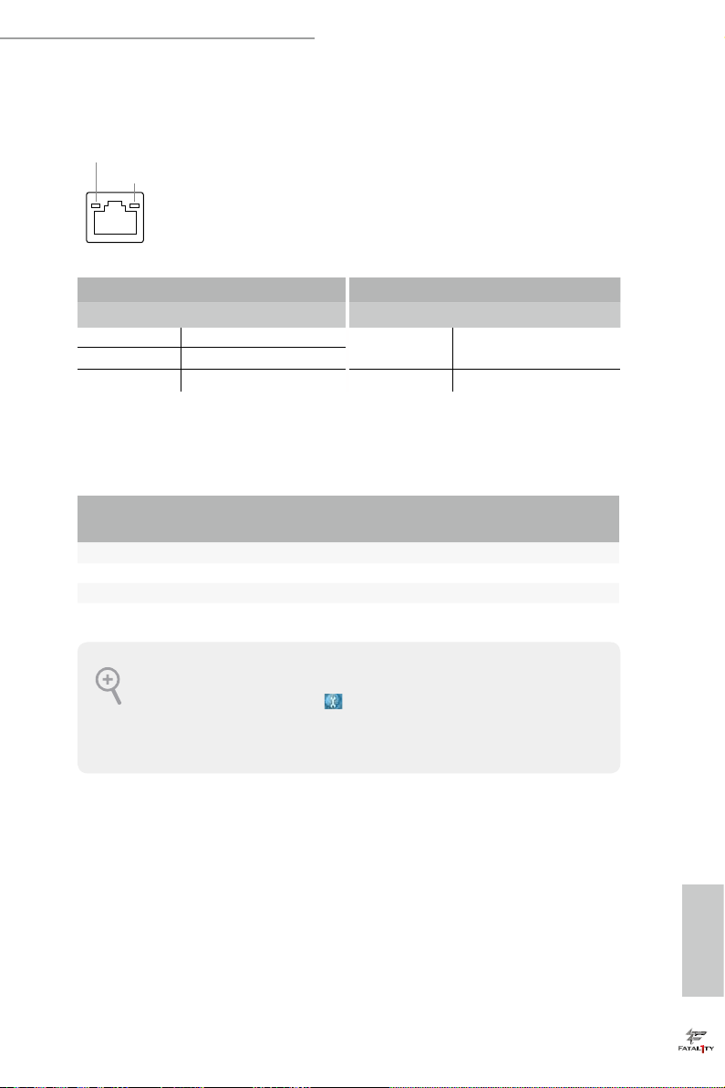
** ere are two LEDs on each LAN port. Please refer to the table below for the LAN port LED indications.
ACT/LINK LED
SPEED LED
LAN Por t
Activity / Link LED Speed LED
Status Description Status Description
O No Link Orange 100Mbps/1Gbps/2.5Gbps
Blinking Data Activity
On Link Green 10Gbps connection
*** If you use a 2-channe l speak er, plea se connect the speaker’s plug into “Front Speaker Jack”. See the table below
for connection d etails in accordance w ith the type of speaker you use.
/5Gbps connection
Audio Output
Channels
Front Speaker
(No. 8)
Rear Speaker
(No. 6)
Central / Bass
(No. 5)
2 V -- -- --
4 V V -- --
6 V V V --
8 V V V V
To enable Multi-Streaming, you need to connect a front panel audio cable to the front
panel au dio header. Aer re starting your computer, you will nd the “Mixe r” tool on your
system. Plea se sele ct “Mixe r To olBox” , click “Enable playback multi-streaming”, an d
click “ok”. Choose “2CH”, “4CH”, “6CH”, or “8CH” and then you are a llowed to select
“Realtek HDA Primary output” to u se the Rear Speaker, Central/Ba ss, and Front Speaker,
or select “Realtek HDA Audio 2nd output” to use the front panel audio.
**** ACPI wake-up function is not supported on USB_ 3_4 ports.
Line In
(No. 7)
English
11

1.5 WiFi-802.11ac Module and ASRock WiFi 2.4/5 GHz Antenna
WiFi-802.11ac + BT Module
is motherboard comes with an exclusive WiFi 802.11 a/b/g/n/ac + BT v4.2
module (pre-installed on the rear I/O panel) that oers support for WiFi 802.11 a/b/
g/n/ac connectivity standards and Bluetooth v4.2. WiFi + BT module is an easy-to-
use wireless local area network (WLAN) adapter to support WiFi + BT. Bluetooth
v4.2 standard features Smart Ready technology that adds a whole new class of
functionality into the mobile devices. BT 4.2 also includes Low Energy Technolog y
and ensures extraordinary low power consumption for PCs.
* e transmission speed may vary according to the environment.
English
12
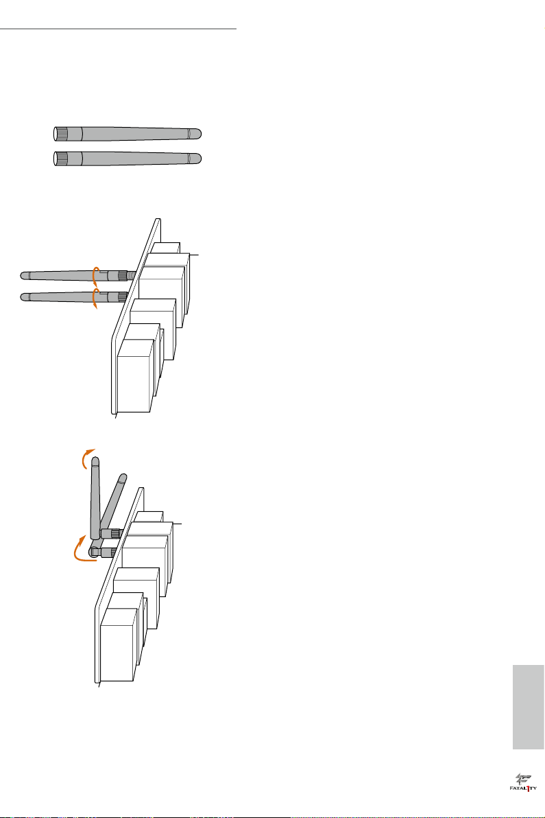
WiFi Antennas Installation Guide
Fatal1ty Z370 Professional Gaming i7 Series
Step 1
Prepare the WiFi 2.4/5 GHz Antennas that come
with the package.
Step 2
Connect the two WiFi 2.4/5 GHz Antennas to
the antenna connectors. Turn the antenna clock-
wise until it is securely connected.
Step 3
Set the WiFi 2.4/5 GHz Antenna as shown in the
illustration.
*You may need to adjust the direction of
the antenna for a stronger signal.
English
13

Chapter 2 Installation
is is an ATX form factor motherboard. Before you install the motherboard, study
the conguration of your chassis to ensure that the motherboard ts into it.
Pre-installation Precautions
Take note of the following precautions before you install motherboard components
or change any motherboard settings.
• Make sure to unplug the power cord before installing or removing the motherboard
components. Failure to do so may cause physical injuries and damages to motherboard
components.
• In order to avoid damage from static electricity to the motherboard’s components,
NEVER place your motherboard directly on a carpet. Also remember to use a grounded
wrist strap or touch a safety grounded object before you handle the components.
• Hold components by the edges and do not touch the ICs.
• Whenever you uninstall any components, place them on a grounded anti-static pad or
in the bag that comes with the components.
• When placing screws to secure the motherboard to the chassis, please do not over-
tighten the screws! Doing so may damage the motherboard.
English
14
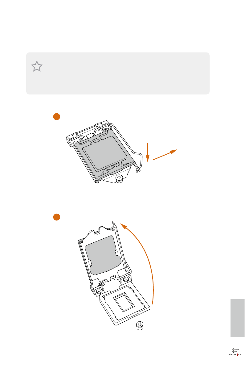
2.1 Installing the CPU
1. Before you insert the 1151-Pin CPU into the socket, please check if the P nP cap is on the
socket, if the CPU surface is unclean, or if there are any bent pins in the sock et. Do not
force to in sert the CPU into the socket if above situation is found . Otherwise, the CPU
will be seriously damaged.
2. Unplug all power c ables before in stalling the CPU.
1
Fatal1ty Z370 Professional Gaming i7 Series
A
B
2
English
15
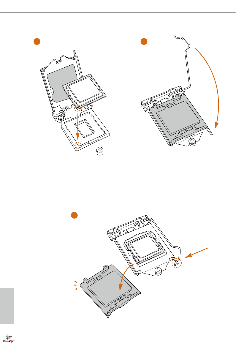
3
4
English
16
5

Fatal1ty Z370 Professional Gaming i7 Series
Please save and replace the cover if the processor i s removed. e cover must be placed if
you wish to return the motherboard for aer service.
17
English
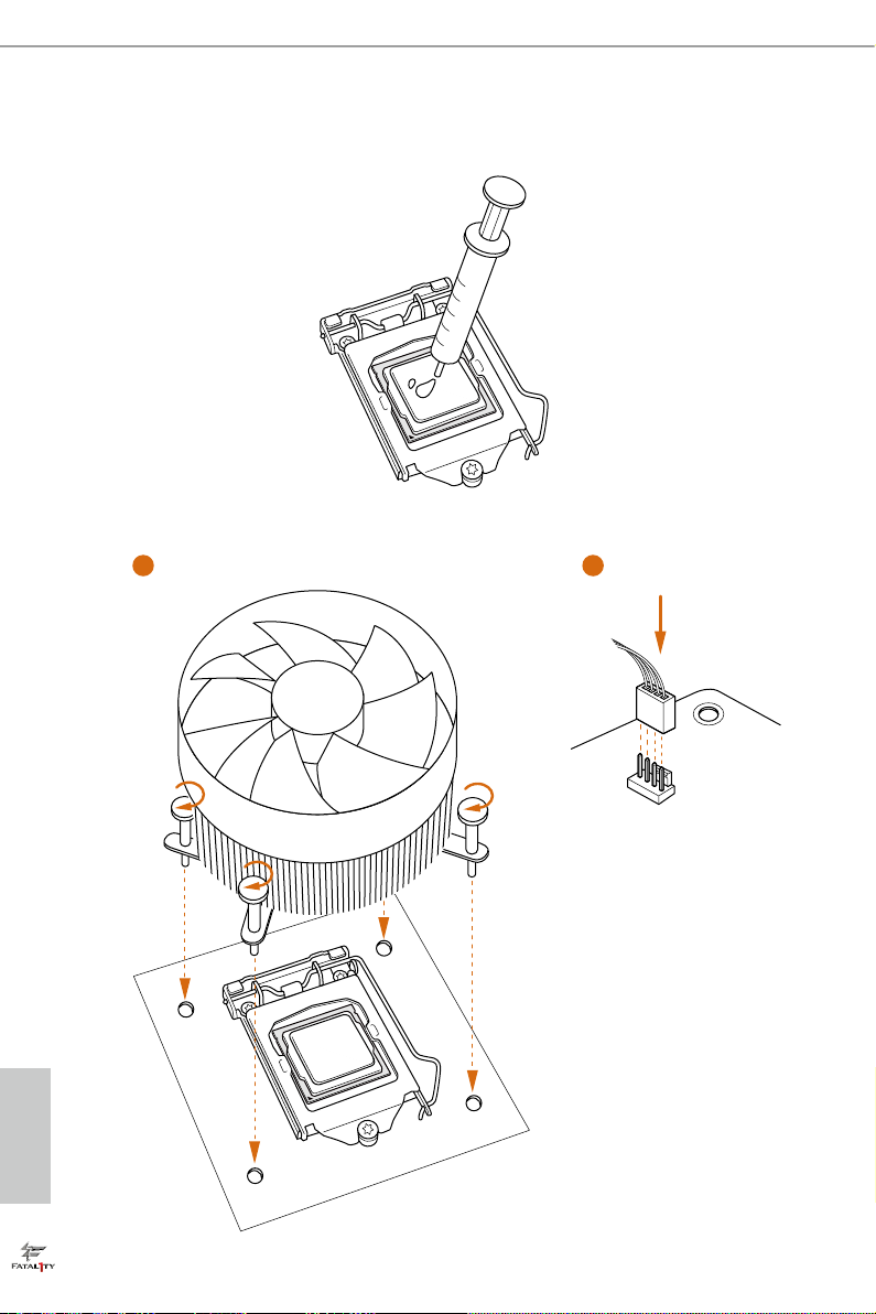
2.2 Installing the CPU Fan and Heatsink
1 2
English
18
FAN
CPU_
Fatal1ty Z370 Professional Gaming i7 Series
2.3 Installing Memory Modules (DIMM)
is motherboard provides four 288-pin DDR4 (Double Data Rate 4) DIMM slots,
and supports Dual Channel Memory Technology.
1. For dual channel cong uration , you always need to in stall identical (the same
brand, speed , size and chip-type) DDR4 DIMM pairs.
2. It is unable to activate Du al Channel Memory Technology with only one or three
memory module installed.
3. It is not allowed to install a DDR, DDR2 or DDR3 memory module into a DDR4
slot; otherwise, this motherboard and DIMM may be damaged.
Dual Channel Memory Conguration
Priority DDR4_A1 DDR4_A2 DDR4_B1 DDR4_B2
1 Populated Populated
2 Populated Populated Populated Populated
e DIMM only ts in one correct orie ntation. It will cause permanent dam age to
the motherboard and the DIMM if you force the DIMM into the slot at incor rect
orientation.
19
English

1
2
English
20
3

Fatal1ty Z370 Professional Gaming i7 Series
2.4 Expansion Slots (PCI and PCI Express Slots)
ere are 5 PCI Express slots on the motherboard.
Before installing an ex pansion card, please make sure that the power supply is
switched o or the power cord is unplugged. Plea se read the documentation of the
expan sion card and mak e necessary h ardware settings for the card before you start
the installation.
PCIe slots:
PCIE1 (PCIe 3.0 x1 slot) is used for PCI Express x1 lane width cards.
PCIE2 (PCIe 3.0 x16 slot) is used for PCI Express x16 lane width graphics cards.
PCIE3 (PCIe 3.0 x1 slot) is used for PCI Express x1 lane width cards.
PCIE4 (PCIe 3.0 x16 slot) is used for PCI Express x8 lane width graphics cards.
PCIE5 (PCIe 3.0 x16 slot) is used for PCI Express x4 lane width graphics cards.
PCIe Slot Congurations
PCIE2 PCIE4 PCIE5
Single Graphics Card x16 N/A N/A
Two Graphics Cards in
CrossFireXTM or SLITM
Mode
ree Graphics Cards in
3-Way CrossFireXTM Mode
For a better ther mal environme nt, ple ase connect a ch assis fan to the motherboard’s
chassis fan connector (CHA_ FAN1, CHA_ FAN2 or CH A_FAN3) when using multiple graphics cards.
x8 x8 N/A
x8 x4 x4
English
21
 Loading...