

Page 1
Type: TD25
Service manual
This service manual describes tumble dryer type TD25 and is a supplement to the general service manual
for the 700 series.
Contents
Introduction ................................................................................................................................................... 3
Product overview ..........................................................................................................................................
4
Programme ...................................................................................................................................................
5
Indication of programme sequence ...............................................................................................................
5
Options and settings .....................................................................................................................................6
Variant settings .............................................................................................................................................
7
Test programme ............................................................................................................................................
8
Troubleshooting ..........................................................................................................................................
10
Components and measurement values ......................................................................................................
12
Technical data .............................................................................................................................................
13
Wiring diagram
............................................................................................................................................14
Appendix: Timer diagram TD25 ......................................................................................................................
Page 2

Service manual TD25
2
Page 3
Service manual TD25
3
Introduction
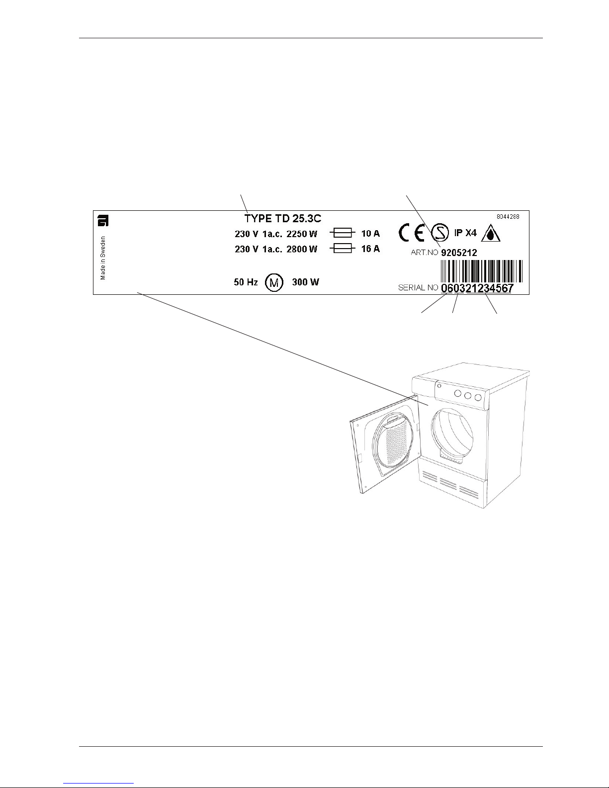
You are holding the service manual for the TD25 generation of tumble dryer.
There are two types of tumble dryer in the TD25 series: TD25.1 and TD25.3. The following page presents
the different versions, to help you identify the machine types. The variants are named differently from mar
ket to market. The type designation is the most important factor for identifying the machine type. The type
designation can be found on the machine plate, which is located inside the machine’s door.
It should be easy to service a tumble dryer. It is important that you, as a service technician, are given the
conditions to be able to carry out work in an efficient and satisfactory way. Our hope is that this service
manual is a useful tool for your daily work.
Typbeteckning Produktnummer
Löpnummer
År Vecka
Type designa-
Product number
Week
Serial number
Page 4
Service manual TD25
4
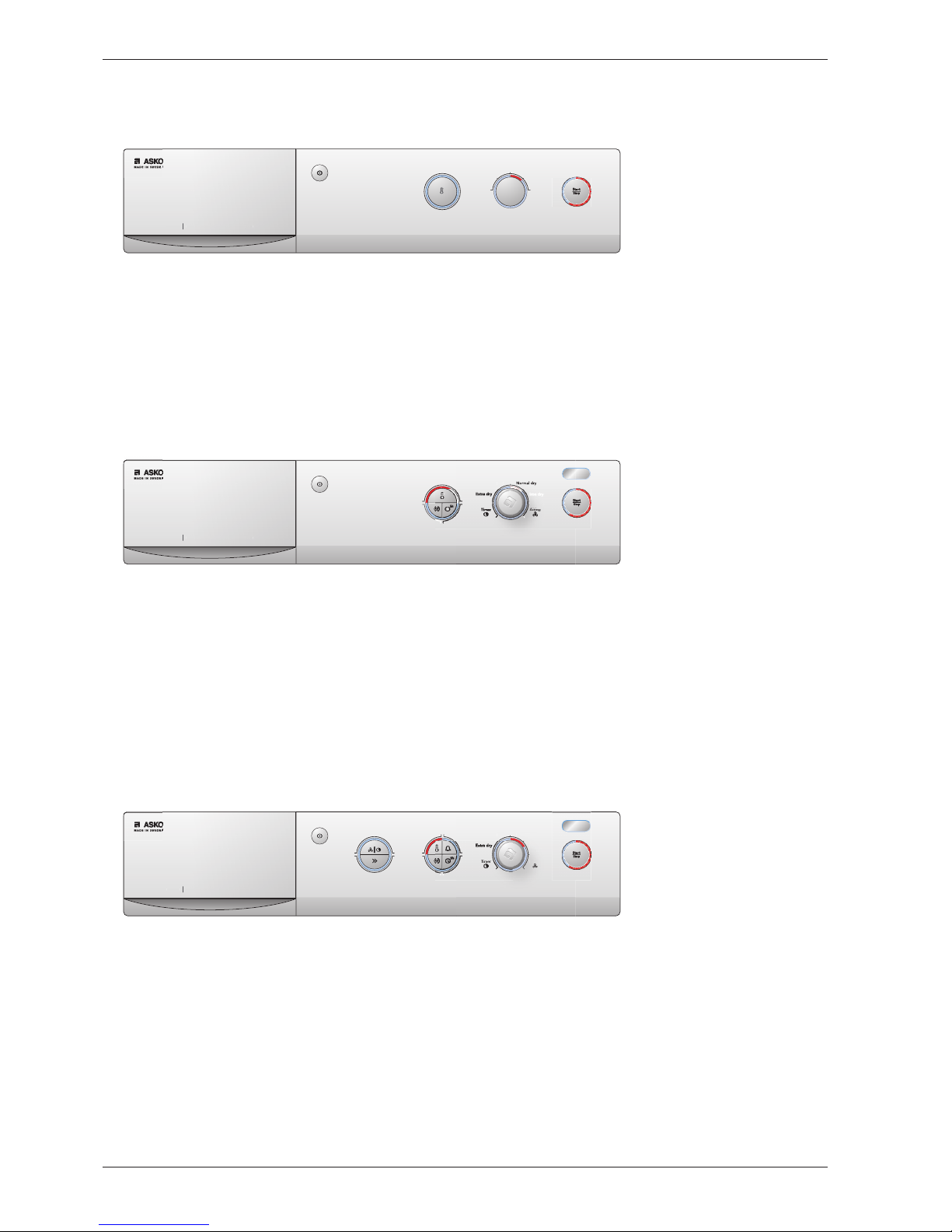
TD25.3
Programme: 4 automatic programmes, 1 timer programme and 1 airing programme (For further infor-
mation, see the timer diagram at the foot of the document.)
Options: 4 (designations differ depending on the market, see directions for use.)
Settings: Temperature.
2h
minm
in
Airin
g
Normal dr
y
Iron dr
y
Dr
y
T75 2
BUT T E R F L Y D R Y I N
G
Type overview
TD25.1
Programme: 4 automatic programmes (For further information, see timer diagram at the foot of the
document.)
Options None.
Settings: Temperature.
T 7 1 2
BUT T E R F L Y D R Y I N
G
Program
Temperature
Extra dry
Dry
Normal dr
y
Iron dr
y
TD25.3
Programme: 4 automatic programmes, 1 timer programme and 1 airing programme (For further infor-
mation, see the timer diagram at the foot of the document.)
Options: 2 (designations differ depending on the market, see directions for use.)
Settings: Temperature.
T73 2
BUT T E R F L Y D R Y I N
G
Dr
y
Page 5

Service manual TD25
5
Programme
When using tumble dryer TD25 it is possible to choose between four different programmes that automatically sense how damp the washing is. The machine dries to different levels depending on which of the four
programmes has been selected on the front panel. The machine only has one automatic programme that
runs for different lengths of time (and therefore dries to different levels) depending on which of the four programmes has been selected on the front panel. The automatic programme runs for a maximum of 3 hours.
The machine has a Timer programme that runs for the time that is set (20 minutes – 2 hours), regardless of
whether the washing is dry or not.
The machine has an Airing programme that blows cold air for the time that is set (5 minutes – 2 hours).
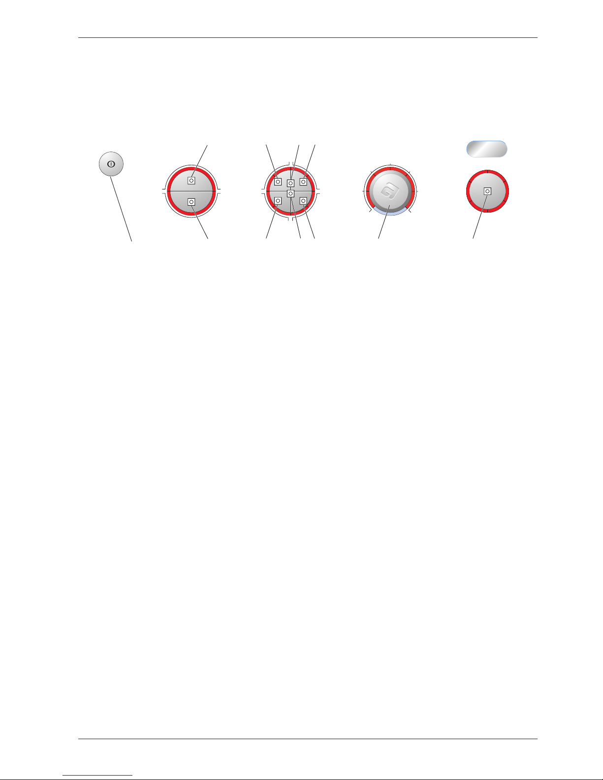
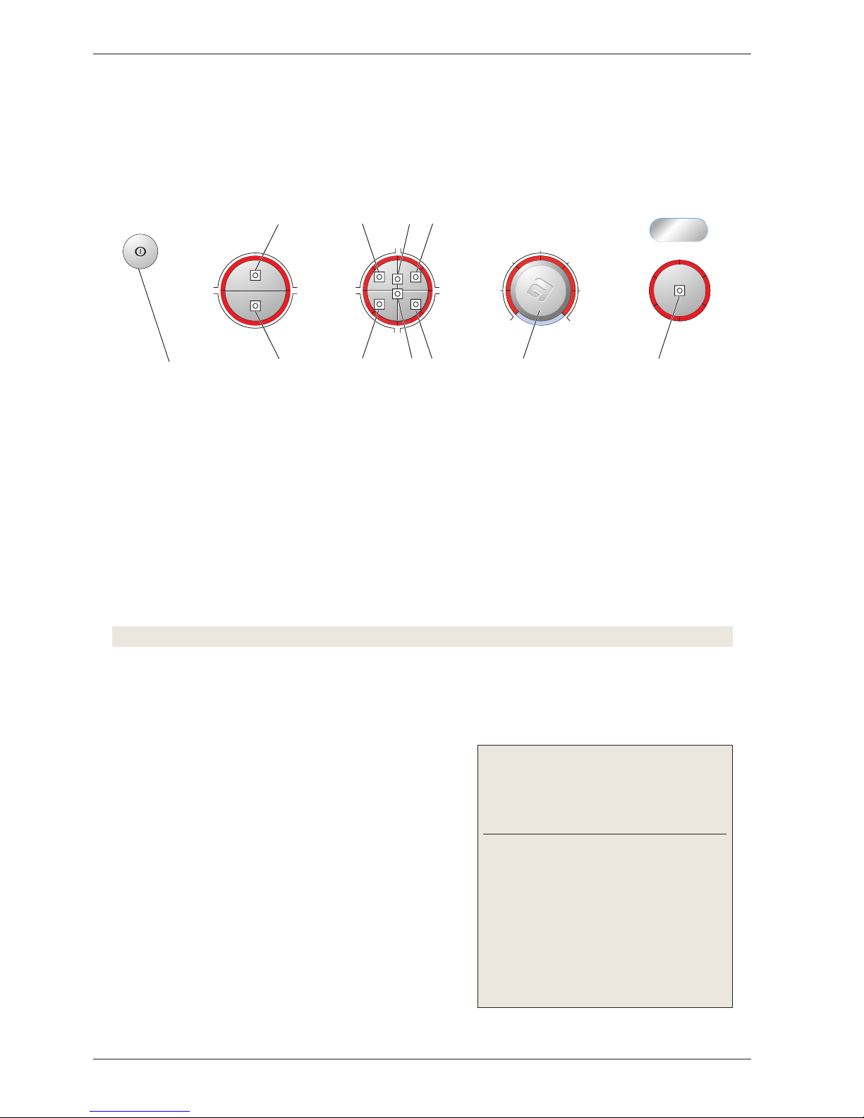
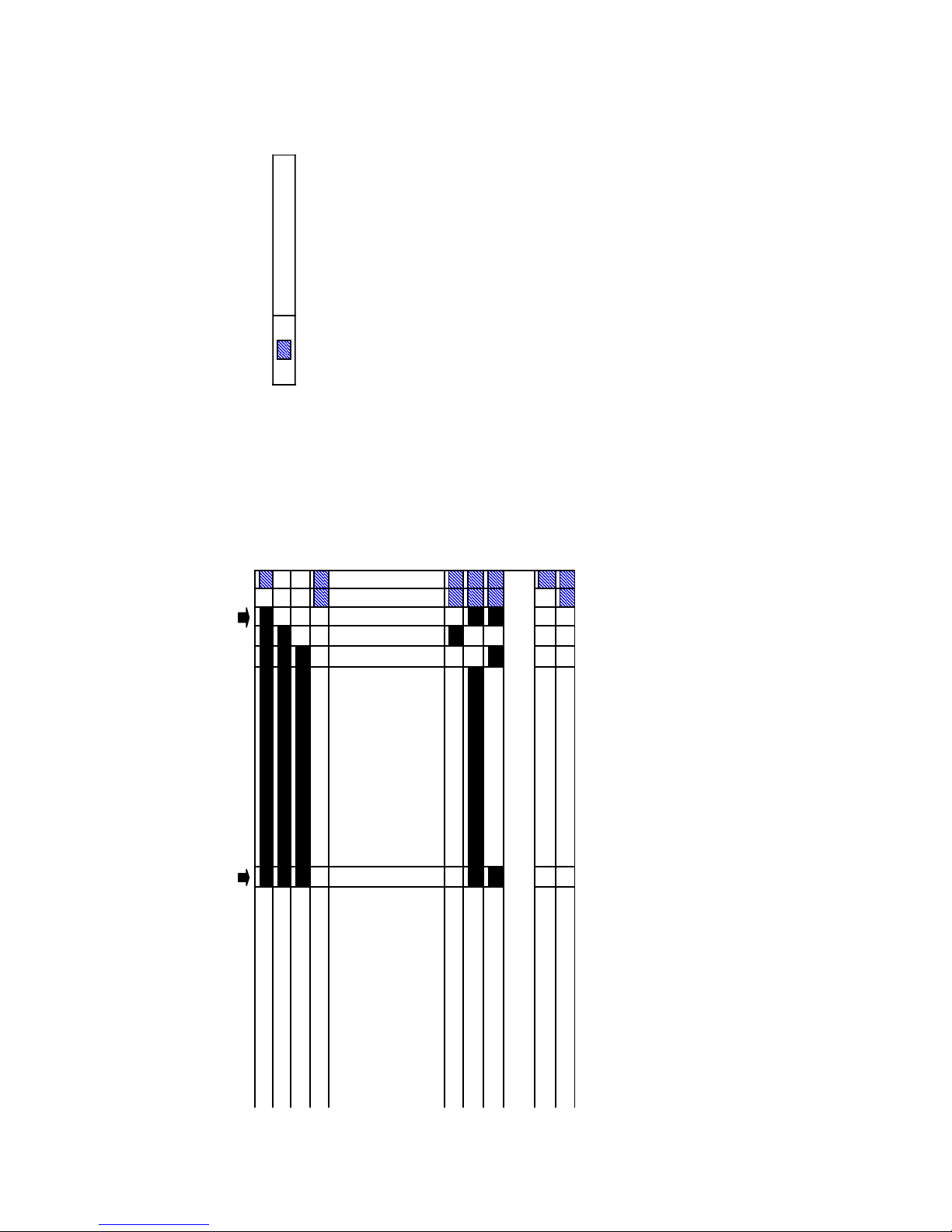
Indication of programme sequence
During the programme, the current programme sequence is indicated by a fixed light in the LEDs around
the start/stop button (see the image).
The cycle time is calculated during the start sequence.
Note!
If the door is opened whilst a programme is in operation, the programme will be interrupted and return to
the start position.
Start
End
Cooling
¼ cycle time
¾ cycle time ½ cycle time
Page 6
Service manual TD25
6
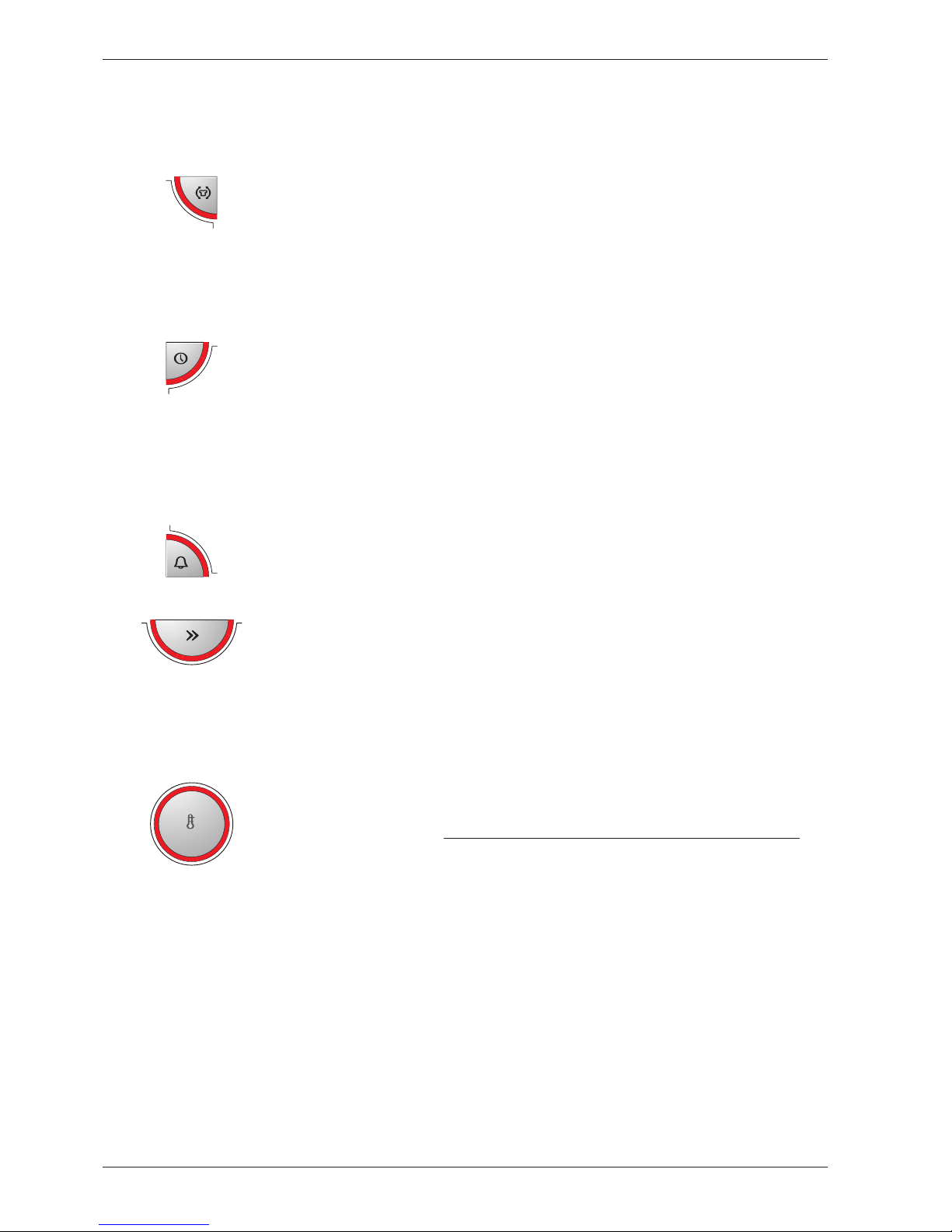
Options and settings
Options
2h
Means that the drum will rotate 3 seconds per minute for 2 hours once the drying
programme has finished. The option prevents the fabrics from remaining in the
same position and becoming creased, which is good if you are unable to remove
them immediately after tumble-drying has finished.
If the Buzzer is also activated
a signal will sound each time the drum rotates, as a reminder that the drying pro
-
gramme has finished.
5h
Delays the start of the machine by 5 hours.
Activated by pressing the Time-delayed start button and then the start/stop but
-
ton.
The number 5 in the display indicates that Time-delayed start has been activated.
The number of hours to start is displayed with a countdown from 5 to 1.
Deactivated by pressing the start/stop button for 3 seconds until the red field next to
Time-delayed start goes out.
This means that a buzzer will sound for 3 seconds when the drying programme
finishes.
Reduces cooling to 3 minutes.
Cannot be used in the Airing programme.
(In ”normal cases” when Short cooling is deselected, the machine cools for 15
minutes. )
Settings
Possible to set to a high or low temperature.
High temperature Low temperature
Airing dryer:
57°C 43°C
Condenser dryer:
73°C 50°C
Temperature setting cannot be carried out in the airing programme.
Page 7
Service manual TD25
7
Variant settings
The following version settings can be made after replacing the control unit.
Total reset
1. Hold the start/stop button (S1) in, start the machine by pressing the main power switch and keep the
start/stop button depressed until one of the LEDs on the panel lights.
Buzzer
1. Hold S5 or S6 pressed in, start the machine by pressing the main power switch and keep S5/S6
pressed in until L1, L13 and L15 start to flash.
2. Change the setting by pressing J1/S2. L8 lights when the buzzer is activated.
3. Confirm your selection by pressing the start/stop button (S1).
10 A or 16 A
1. Hold the start/stop button (S1) in, start the machine by pressing the main power switch and keep the
start/stop button depressed until one of the LEDs on the panel lights.
2. Press the start/stop button (S1) 5 times. L1 starts to flash.
3. Change the setting by pressing S2 or J1. L8 lights when 16 A is activated.
4. Confirm your selection by pressing the start/stop button (S1).
Adjusting drying time
1. Hold the start/stop button (S1) in, start the machine by pressing the main power switch and keep the
start/stop button depressed until one of the LEDs on the panel lights.
2. Press the start/stop button (S1) for a further 5 seconds until L1 starts to flash.
3. Change the setting by pressing S2 or J1. The selected setting is indicated as follows:
No adjustment: no LED:
+ 5 minutes:
L8
+10 minutes: L9
+15 minutes:
L10
+20 minutes:
L11
4. Confirm your selection by pressing the start/stop button (S1).
The control unit detects and adjusts automatically to the panel layout and machine model when the option
buttons are pressed several times.
L19
L1
L2
L3
L6
L4
L5
L10
L11
L12
L9
L7
L13
L14
L15
a
a
a
a
b
b
b
b
L16
L17
L18
L8
S1
S8 S4S6
S10
S9 S3
S5
S7
J1/S2
Main power switch
S = Push button
L = LED
Page 8
Service manual TD25
8
Total reset of programmes
To access the test programme, total reset of the programme must be carried out as follows:
1. Cancel the current programme and switch off the machine by pressing the main power switch.
2. Hold the start/stop button (S1) in and start the machine by pressing the main power switch.
3. Check that any of the LEDs around the programme knob (L7 – L12) lights. This indicates that total
reset has been carried out.
Starting the test programme
4. Press button S7 (left-hand button on divided options button) and keep it pressed for approximately 20
seconds.
Note! This must be done within 3 seconds after carrying out total reset.
• All LEDs except L17 and L18 light up continuously. This indicates that the test programme has been
activated.
Testing the motor and condensing waterpump
5. Press the start/stop button (S1).
• LED L6 lights up and is lit for the entire test program
-
me.
• Condenser dryer: LED L8 lights up.
• Airing dryer: LED L7 lights up.
• The motor and condensing waterpump starts.
• Water fills the housing for the water tank until the
machine stops (check that the switch for condensation
water works).
6. Press the start/stop button (S1) to start the motor and
pump out the condensation water.
• LED L 2 lights up and is lit for the remainder of the test
programme.
Indication of faults:
Fault indication/symptom
Cause
The condensing
waterpump pumps until
S1 is reactivated and
L7 lights up (applies to
airing dryers).
The rear thermistor
does not have any contact or is damaged.
The motor will not start. Motor or cable fault
The condensing water
-
pump does not start.
Switch or cable fault
Test programme
The entire test programme is run in a sequence as follows. You can cancel the test programme at any time
during the programme by opening the door or pressing the main power switch.
L19
L1
L2
L3
L6
L4
L5
L10
L11
L12
L9
L7
L13
L14
L15
a
a
a
a
b
b
b
b
L16
L17
L18
L8
S1
S8 S4S6
S10
S9 S3
S5
S7
J1/S2
Main power switch
S = Push button
L = LED
Page 9

Service manual TD25
9
Testing the element, thermistor and temperature regulation
7. Press the start/stop button (S1).
• LED L3 starts to flash and the large element loop acti
-
vates.
8. Press the start/stop button (S1).
• LED L3 lights continuously and the machine runs heat
regulation for 15 minutes.
• LED L4 starts flashing, which means that temperature
regulation is finished.
• Cooling runs for 5 minutes.
• The machine stops.
Indication of faults:
Fault indication/symptom
Cause
The element does not
start.
Element or cable fault
The programme stops.
F9 is shown in the dis
-
play (applies to machi
-
nes with a display).
The front thermistor is
not connected.
Testing the interval time and buzzer tone
9. Press the start/stop button (S1).
• LED L4 lights up.
• The motor starts and runs at intervals at the same time
as a buzzer sounds.
Indication of faults:
Fault indication/symptom
Cause
No buzzer tone Fault in control
Cancel the test programme.
10. Press the start/stop button (S1).
• The test programme stops and ”End” is shown in the display (applies to machines with a display).
Page 10
Service manual TD25
10
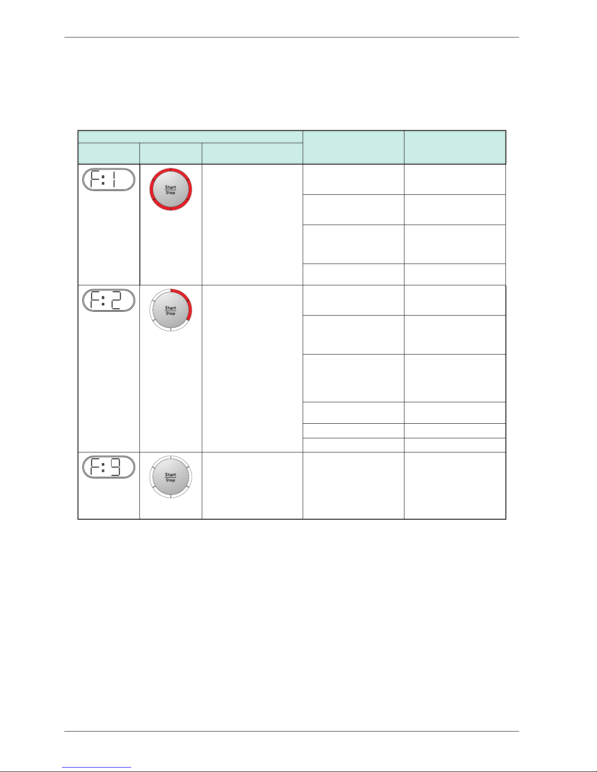
Troubleshooting
Fault indications
The following faults are indicated by a flashing red light in the start/stop button LEDs and as a trouble code
on the display (display not available on all machine versions).
Fault indication Cause Action
Display
LEDs
(flashing)
Meaning
Overfilling
The machine stops.
(applies to condenser
dryers)
The condensation water tank
is full.
Check if the customer has:
• Emptied the tank and
restarted the machine
Condensing waterpump or
hoses blocked.
• Clean hoses and check
voltage and resistance in
the drain pump.
Float/float switch is defective. • Check that the float has
not got “stuck” and check
the function of the microswitch.
The control unit is faulty (the
pump does not start).
• Replace control unit.
Maximum permitted programme time
The machine stops after 3
hours.
The washing has been spun
at too low a speed, i.e. less
than 800 rpm.
Check if the customer has:
• Tried spinning at a higher
speed
The control unit did not have
chance to reset, but added
the time to the next drying
cycle.
Check if the customer has:
• Has the machine switched
off for 30 minutes before
restarting
High ambient temperature
combined with low element
output and low drying tempe
rature leads to condensation
formation.
Check if the customer has:
• Attempted to select an
-
other programme
• Good ventilation in the
room
Poor condensation due to
blocked external air
• Ensure that the external air
has free passage.
Defective thermistor. • Replace the thermistor.
Defective control unit • Replace control unit.
(no indication in
LEDs)
Thermistor fault
The machine stops.
The front thermistor is de
fective or the control is not in
contact with it.
• Replace the thermistor.
After carrying out corrective actions as above, reset the fault indications by switching off the machine using
the main power switch.
Page 11
Service manual TD25
11
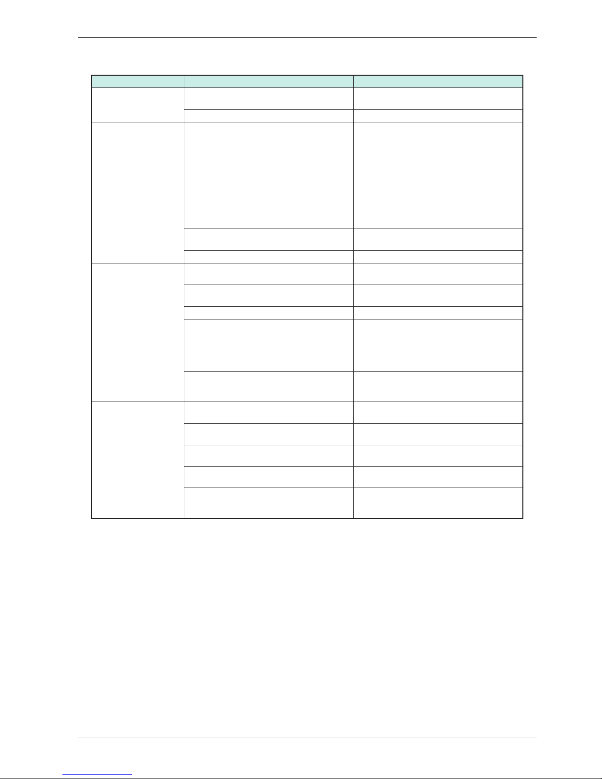
Other faults
Fault symptom Cause Action
The machine will not start. The outer door is not properly closed. • Check that the door pin is activating the door
switch.
The machine is not supplied with power. • Check the fuses and connections.
The machine stops. The automatic overheating protection has tripped.
Check if the customer has:
• Opened the door and cleaned the filter and
condenser unit
• Left the door open long enough for the overheating protection to be reset
and the display and LEDs to light up
• Attempted to restart the programme
Service action:
• Clean internal fan wheel, condenser, air ducts
and element.
• Check the seals.
The overheat protection in the motor has been
tripped.
• Clean and check the motor.
• If necessary, replace the motor.
Defective control unit • Replace control unit.
The washing does not
get dry.
Air leakage at the door seals is affecting the
drying results. • Check the sealing strips.
Air leakage around the motor shaft affects the
drying result.
• Check the seal around the motor shaft.
Defective rear thermistor • Replace the thermistor.
Defective control unit • Replace control unit.
Drying is uneven. Mixing of various types of items can lead to une
-
ven drying results.
Customer information:
• Check that different types of items are not
mixed in the same machine. Remove the dry
items.
How full the machine is affects the drying results.
Customer information:
• Check that the machine is not overfilled. Remove some of the washing if necessary.
Tumble-drying takes too
long.
The lint filter is blocked.
Customer information:
• Cleaning the lint filter.
The condenser unit is blocked.
Customer information:
• Clean the condenser.
The washing machine’s spinning affects drying.
Customer information:
• Spin at a minimum of 800 rpm.
The machine is in a room with poor ventilation.
Customer information:
• Open doors to adjacent rooms.
The evacuation hose is too long, blocked or bent.
Customer information:
• Try to make the hose length as short as pos
-
sible with as gentle bends as possible.
Page 12
Service manual TD25
12
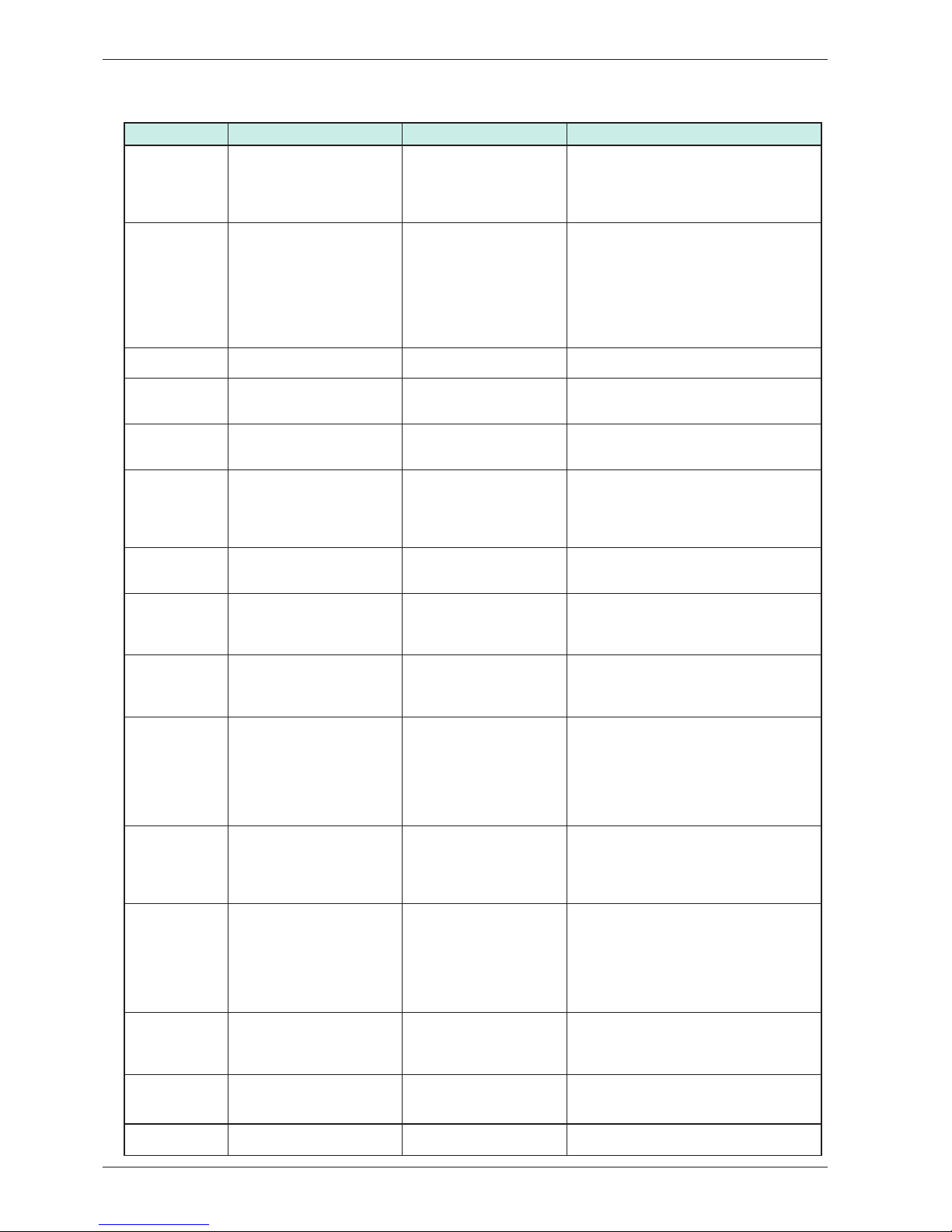
Components and measurement values
Item number Component Measurement value Comments
80 790 43 Motor 50 Hz,
220/240 V
Main winding: 23.8 Ω
Auxiliary winding: 28.1 Ω
Current: 1.1 A; 270 W;
2850 rpm
80 766 90 Motor 60 Hz, 220/240 V Winding resistance:
cable colour grey-blue
25.5 Ω
cable colour grey-red
16.0 Ω
Current: 0.9 A; 200 W;
3300 rpm
The motor is a 2-pin motor and is directly
connected to the fan for internal air and
gearing for driving the cylinder. The fan for
external air is also driven on condenser
dryers. All resistance values have toleran
-
ces of ±7 %.
80 801 19 Capacitor 8 μF, 400V The capacitor is mounted on the motor.
80 638 09 Condensing waterpump
25W
111 Ω
80 762 02 EMC filter with inductor The filter eliminates interference to and
from the machine.
80 762 24 Thermistor 40 – 60 kΩ (at room tem-
perature 20 – 30°C)
The thermistor controls temperature
regulation. If the thermistor is short-circuited or detaches from the control unit, the
programme is cancelled.
80 792 00 Thermostat (135°C) The thermostat automatically disconnects
the heating loop at too high temperatures.
80 773 85 Thermostat/Overheating
protection
(150°C automatic)
The thermostat
/overheating protection interrupts the
programme at too high temperatures.
80 797 37 Thermostat/Overheating
protection , 150°C (USA)
The thermostat/overheating protection
interrupts the programme at too high
temperatures.
80 761 04 Door switch The front door affects a door switch,
which interrupts the programme when
the door is opened. If the door has been
opened and closed during the programme
the machine must be restarted using the
start/stop button.
80 761 03 Microswitch float If both containers are overfilled the pro-
gramme is interrupted by a float switch
located on the lower holder. Overfilling is
indicated in the display.
Electrical connection The machine is delivered as single phase
and can be switched between 1950 W, 10
A and 2500 W, 16 A.
Adjustment between 1950 W / 10 A and
2500 W / 16 A is carried out using soft
-
ware via buttons.
80 771 30
80 771 32
Control Unit (TD25.1)
Control Unit (TD25..3)
The control unit contains microproces
sors for controlling programmes, motor,
element etc.
80 762 26 Heating Element 2500W
80 762 27 Heating Element 3000W
Page 13
Service manual TD25
13
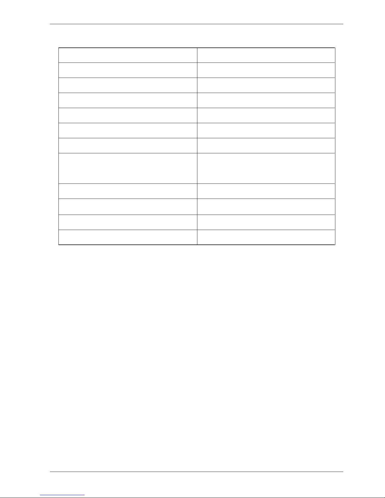
Technical data
Height: 850 mm
Width: 595 mm
Depth: 585 mm
Weight: 47 kg
Cylinder volume:
111 l
Max. washing capacity: 6.0 kg
RPM: 52 rpm
Rated power: 1950 W = 10 A
2500 W = 16 A
Adjustment between 10 and 16 A is carried out
using software via buttons.
Drying drum material:
Stainless steel
Outer casing material: Powder-coated and hot-galvanized sheet steel or
stainless steel
Set-up: Stacking or freestanding
Protection class:
IP X4
Page 14
Service manual TD25
14
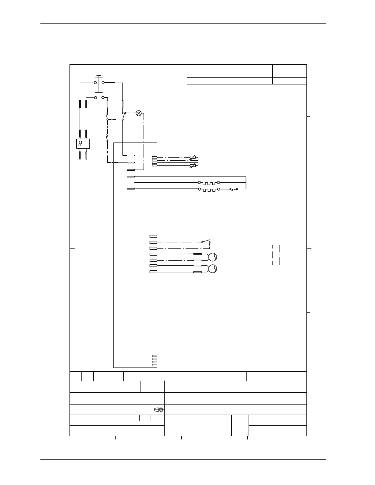
Wiring diagram
WIRES IN ALL MACHINES
INTERNAL CONNECTION
M
B
AP
550 / 1050 W
1950 W
AP: DRAIN PUMP
EL: HEATING ELEMENT
F: FILTER
NTC: THERMISTOR
TB: MAIN SWITCH
FB: FLOAT SWITCH
DO: DOOR SWITCH
T1: THERMOSTAT, OVERHEATING (HEATER)
T2: THERMOSTAT, FAN HOUSING
T3: THERMOSTAT (HEATER)
M: MOTOR
B: INTERIOR LIGHT
FB
T1
T3
TB
F
NTC 1
1
4
7
Home
L
N
E
L
T
B
3
4
5
6
4 23
FORMAT A4
1
A
F
C
Year Week
D
B
Revision
E
Appd
Rev ind
This document must not be copied without
our written permission, and the contents
thereof must not be imparted to a third party
nor be used for any unauthorized purpose.
Contravention will be prosecuted.
Asko Cylinda AB
Dimensions, Type, etc.
Pos.
Material
Name of item
Qty
Dens.Kg/dm3
Part No.
Material
ASKO CYLINDA
Description(ENG)
Gen.tolerance
Scale
Description(SE)
Replace
Gen.tol.Angle
Rev Ind
Designed by
Project
Week
Year
Iss by Dept
Released by
Pema
03 28
KOPPLINGSSCHEMA TD25
80 791 01-01
CIRCUIT DIAGRAM TD25
TD25
80 761 01
02
S:\U\WMD25\1_Tryckunderlag\Kopplingsschema\8076101 Kopplingsschema TD25\8076101 Circuit diagram TD25-02.dft , pema , 2005-11-10 15:00:44
UT
NTC 2
ALTERNATIVE WIRING
DB
*A
*B
*A
*A
*A CONDENSE DRYER
*B WITH INTERIOR LIGHT
T2
PM
PM 05 44
05 45
01
02
Drawing updated
Drawing updated
Page 15
Service manual TD25
15
Notes
80 800 48 Rev 1 Service maual
Page 16
Product information TD25
Пуск
Компоненты
Временные инт
Программа
Режимы
Предотвращение измятия
Охлаждени
е
Пояснения к таблице
По выбору
Зуммер
3 сек. вкл., 57 сек. В
ы
3 мин - 15 мин
3 сек
Проветривание
Автоматическая программа
Временная программа
Временная диаграмма (описание процесса выполнения программы) TD25
Электродвигатель
2'
Дренажный насос (30 сек. вкл., 210 сек.
Нагревательный элемент
Зуммер
Программа сушки (макс. 3 часа)
20 минут - 2 часа
5 минут - 2 часа
Appendix: Timer diagram Page 1
 Loading...