

Page 1

Dear Customer,
Read these instructions carefully and completely before you install the
machine. The installation should be carried out by a qualifi ed person who
is familiar with all local codes and ordinances for electrical and plumbing
connections. See also the general Safety Instructions in the Use & Care
Guide.
Cosmetic damage must be reported to the ASKO dealer within fi ve
days from the date of purchase. As soon as you unpack the machine,
thoroughly check it for cosmetic damage.
Installation instructions for condenser tumble dryer
DOMESTIC
Page 2

Installation instructions
WARNING!
WARNING - Risk of fi re.
Install the clothes dryer according to the
manufacturer's instructions and local codes.
To reduce the risk of of severe injury or death,
follow all installation instructions.
SAVE THESE INSTRUCTIONS FOR FUTURE
REFERENCE.
Freestanding
The tumble dryer can be positioned beside the
washing machine.
Stacking
The tumble dryer can be placed on top of an
ASKO washing machine. Use the two foot cups
found in the document bag included with the
machine and the two tip guards attached to the
bottom of the back of the machine.
Positioning the tumble dryer
The tumble dryer can be freestanding or
stacked. Remember that the tumble dryer
produces heat and should therefore not be
located in a room that is too small. If the room
is very small, drying will take longer due to the
limited quantity of air.
NOTE!
Do not install the machine in a room where
there is a risk of frost occurring. At temperatures
around freezing point the machine may not be
able to operate properly.
The room in which the appliance is installed
should be adequately ventilated, with
temperature between 15°C and 25°C.
WARNING!
• Clothes dryer installation must be performed
by a qualifi ed installer.
• For proper ventilation, the machine should
not be installed behind a door.
• The tumble dryer's toe kick ventilation must
not be blocked by a rug or the like.
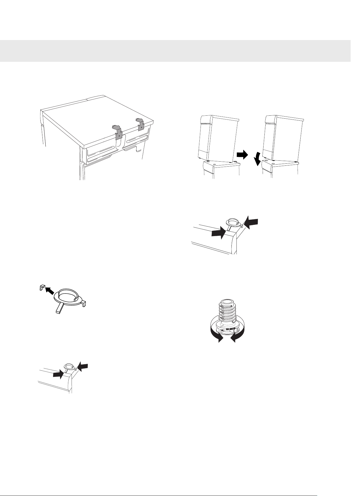
How to assemble the stacking kit:
1. Remove the two tip guards from the back of
the tumble dryer. Replace the screws that
held the tip guards in place.
2. Remove the two screws indicated on the
back of the washing machine.
NOTE!
If the unit must be installed behind a door, the
door should be louvered. (please see door
ventilation requirements in the Built-in chapter).
To improve ventilation, the door where the
tumble dryer is located should be left open
when the dryer is in use.
2
Customer Care Center
1-800-898-1879
www.askona.com
Page 3
Installation instructions
3. Secure the anti-tip device using the screws
as shown in the picture.
4. Attach the plastic cups for mounting the
tumble dryer’s front feet to the washing
machine’s top cover. This is essential, as
only when the tumble dryer’s feet are resting
in the plastic cups can you be sure that the
tumble dryer is correctly positioned on the
washing machine. Break off tab A on the cup
fi tted on the right side and tab B on the cup
fi tted on the left side. Then remove the paper
from the self-adhesive surface under the
plastic cups.
6. Push the tumble dryer in under the metal
brackets. At the same time keep the front
edge raised by 7/16" (10mm) to 7/8" (20mm) .
7. Lower the tumble dryer’s front feet into the
plastic cups and adjust the tumble dryer to
ensure it is level.
Adjusting the feet
Screw the feet in or out so that the tumble dryer
is both stable and level.
A
B
5. Fit the plastic cups so that the "tags" marked
with arrows are against the front edge or side
edge of the cover and press them fi rmly onto
the cover. Then break off the remaining tabs.
Customer Care Center
1-800-898-1879
www.askona.com
3
Page 4
Installation instructions
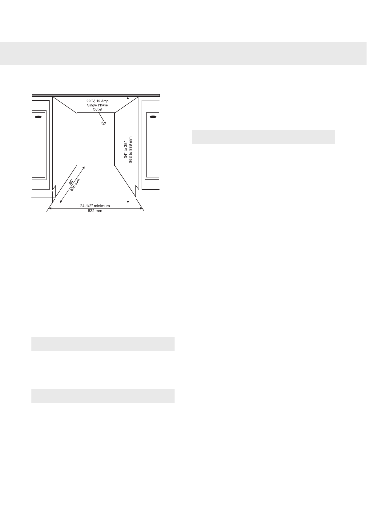
Built-in
ASKO dryers can be installed beneath a cabinet
or worktop with a minimum height of 34” (864
mm). There must be a gap of about 1/2” (12 mm)
all around the machine and a minimum gap of 1"
(25 mm) between the rear edge of the machine
top panel and the back wall. The opening
width must be at least 24-1/2” (622 mm). The
condensing models work best when they have
good air circulation.
Install the dryer so the condensed water will
continuously fl ow into a drain or sink, you
will need a drain outlet behind the unit. The
maximum drain height is 40” (1016 mm).
A buildup of heat could be avoided by:
• Creating a gap for the dryer in the kitchen
furniture plinth facing.
• Creating ventilation gaps in the kitchen unit.
When build under, drying times may be longer.
NOTE!
The dryer should not be installed next to a
refrigeration appliance. The warm air expelled
from the rear of the dryer would increase the
temperature around the refrigeration appliance
heat exchanger causing the compressor to
run continuously. If it is not possible to install
the dryer anywhere else, then the refrigeration
appliance must be sealed off from the dryer.
NOTE!
The height adjustment for the dryer is 33- 1/2”
to 34-1/2” (850 mm to 876 mm). Do not raise it
higher than 34-1/2” (876 mm).
NOTE!
It is very important to avoid a buildup of heat.
The warm air which is expelled from the rear of
the dryer must be able to dissipate.
Warm air which cannot dissipate could cause a
fault.
4
Customer Care Center
1-800-898-1879
www.askona.com
Page 5

Installation instructions
Install in a closet
ASKO's front panel controls make it possible
to install the washers and dryers in a closet.
Make sure there is a ½” (12 mm) minimum
clearance between units and cabinet or wall
and a 1" (25 mm) minimum clearance between
the rear edge of the machine top panel and the
cabinet or wall. To ensure proper ventilation,
we recommend louvered doors, particularly for
condenser dryers. Otherwise there must be
ventilation openings in the door. See illustration
for minimum ventilation openings:
Condensed water
Install the dryer so the condensed water will
continuously fl ow into a drain or sink. To do this,
follow the instructions below:
1 Connect the rubber hose supplied with the
dryer to the blue nipple.
2. Run the hose to a drain or sink, as illustrated.
NOTE!
The drain hose must not be more than 40”
(100 cm) above the fl oor.
NOTE!
Ensure the dryer door can be opened without
hindrance after installation.
NOTE!
NOTE!
• Do not pull on the drain hose and do not
stretch it or allow it to become kinked as it
could get damaged.
• Secure the hose carefully (e.g. by trying it to
a tap to make sure it cannot slip during use).
Otherwise there is a risk of overfl owing water
which could cause damage.
WARNING!
If the tumble dryer is to be connected to a
drainage system already in use by another
appliance it is essential to fi t a non-return valve.
The non-return valve will prevent the risk of
back-fl ow into the dryer which could cause
damage.
The cool air intake panel at the front of the dryer
must not be blocked or covered. Doing so could
cause a fault.
Customer Care Center
1-800-898-1879
www.askona.com
5
Page 6

Installation instructions
Electrical installation
WARNING!
The receptacle on the rear of the machine is
designed to accommodate ASKO washers
ONLY (rated 208–240 V.) To use this receptacle,
you must use the ready-fi tted plug supplied with
the washing machine or an equivalent.
ASKO washers rated 208–240 V have two
internal fuses of 15 A each.
The machine should only be connected to a
grounded wall socket.
WARNING!
This appliance must be properly grounded.
Refer to the “Important Safety Instructions” for
grounding instructions.
The power supply cord must be grounded. If the
machine is to be used in a wet area, the supply
must be protected by a residual current device.
Connection to a permanently wired supply point
must be made only by a qualifi ed electrician.
As supplied: Single-phase, 230 V, 60 Hz,
3000W heater rating 30 A circuit required.
NOTE!
Do not connect the machine to the mains
electricity supply by an extension lead.
Electrical Connections
WARNING!
Read the Electrical requirements and grounding
instructions before connecting the tumble dryer.
Electric models of the dryer are manufactured
for a 3-wire connection system. The dryer frame
is grounded by a link to the neutral conductor
on the dryer terminal block. If local codes do
not permit grounding through the neutral, the
grounding link from the terminal block must be
removed and a separate ground wire must be
used.
Only a 4-conductor cord shall be used when
the appliance is installed in a location where
grounding through the neutral conductor is
prohibited. Grounding through the neutral
conductor is prohibited for new branch-circuit
installations, mobile homes, recreational
vehicles, and areas where local codes prohibit
grounding through the neutral conductors. The
grounding link on the dryer must be removed for
all 4-wire installations.
These Electrical Connection instructions
provide for installing the dryer in the following
situations:
3-wire connection where local codes permit
grounding through the neutral. 3-wire
connection plus separate grounding connector
where local codes do not permit grounding
through the neutral.
4-wire connection.
Each of the above connections can be made
with an approved power supply cord or by direct
wiring. Each connection instruction identifi es
the appropriate Power Supply Cord and covers
requirements for direct wiring.
Remove cover to access
teminal box. (Requires- Torx
screwdriver.)
NOTE!
In Canada, the dryer is delivered ready-fi tted
with a four-prong plug intended for connection
to a single-phase supply.
6
Customer Care Center
1-800-898-1879
www.askona.com
Page 7

Installation instructions
Connecting a 3-wire Power Cord
WARNING!
Before starting this procedure, be sure the
power is turned off at the breaker/fuse box.
Ground
Ground
(center)
Power Supply Cord
You will need a 3-wire power supply cord with
three No. 10 copper wires and a matching
3-wire receptacle of NEMA Type 10-30R, as
illustrated below:
To connect a 3-wire power cord to the dryer,
follow the steps below.
5. Connect ground (center) wire of power
supply cord to the center, silver-colored
terminal screw. Tighten screw.
6. Connect the other wires to outer screws.
7. Tighten the strain relief screws.
8. Replace terminal box cover on back of dryer.
9. Plug dryer into wall receptacle.
10.Turn power on at breaker/fuse box.
Connecting a 4-wire Power Cord
WARNING!
Before starting this procedure, be sure the
power is turned off at the breaker/fuse box.
NOTE!
The numbers in the illustration correlate to the
step numbers.
1. Turn the power off at the breaker or fuse box.
2. Remove terminal block cover.
3. Use the strain relief attached below the
terminal block opening.
4. Loosen or remove center terminal block
screw.
4
6
5
Customer Care Center
1-800-898-1879
www.askona.com
7
Page 8

Installation instructions
Power Supply Cord
You will need a 4-wire power supply cord with
four No. 10 copper wires and a matching 4-wire
receptacle of NEMA Type 14-30R, as illustrated
below.
The fourth wire must be identifi ed with a white
cover and the ground conductor by a green
cover.
To connect a 4-wire power cord to the dryer,
follow the steps below.
NOTE!
The numbers in the illustration correlate to the
step numbers.
1. Turn the power off at the breaker/fuse box.
2. Remove terminal block cover.
3. Use the strain relief attached below the
terminal block opening.
4. Remove center terminal block screw.
4
7
8
6
5. Remove ground wire (green with yellow
stripes) from external ground connector
screw and remove from center terminal
block.
6. Connect ground (green) wire of cord to
external ground conductor screw.
7. Connect neutral (white) wire of cord under
center screw of terminal block.
8. Connect the other wires to outer screws.
9. Tighten the strain relief screws.
10.Replace terminal box cover on back of dryer.
11.Plug dryer into wall receptacle.
12.Turn power on at breaker/fuse box.
8
Customer Care Center
1-800-898-1879
www.askona.com
Page 9

Customer Care Center
1-800-898-1879
www.askona.com
9
Page 10

10
Customer Care Center
1-800-898-1879
www.askona.com
Page 11

Customer Care Center
1-800-898-1879
www.askona.com
11
Page 12

We reserve the right to make changes.
TD70.1C SPK
www.askona.com
en (05-16)
 Loading...