

Page 1

ASKO
USE AND CARE GUIDE
SAVE THESE INSTRUCTIONS FOR FUTURE REFERENCE
omom
om
omom
tingting
ting
tingting
aa
a
aa
or theor the
or the
or theor the
IMPORIMPOR
IMPOR
IMPORIMPOR
erer
er
et the best perfet the best perf
et the best perf
et the best perfet the best perf
o go g
o g
o go g
TT
T
TT
our drour dr
our dr
our drour dr
yy
y
yy
instrinstr
instr
instrinstr
st timest time
st time
st timest time
irir
ir
irir
ff
f
ff
erer
yy
y
yy
uctions befuctions bef
uctions bef
uctions befuctions bef
ANT!ANT!
ANT!
ANT!ANT!
TT
T
TT
ead all operead all oper
ead all oper
ead all operead all oper
r r
r
r r
,,
,
,,
..
.
..
mance frmance fr
mance fr
mance frmance fr
oror
or
oror
e using it fe using it f
e using it f
e using it fe using it f
oror
or
oror
ENGLISHENGLISH
ENGLISHENGLISH
ENGLISH
DRYER
CONTENTS
IMPORTANT SAFETY INSTRUCTIONS 2
SAFETY FEATURES 2
ASKO DRYER FEATURES 3
ENERGY SAVING TIPS 3
INSTALLATION INSTRUCTIONS 4
PREPARING THE LAUNDRY 10
T711 OPERATING INSTRUCTIONS 12
T721 OPERATING INSTRUCTIONS 13
T731 OPERATING INSTRUCTIONS 14
T761 AND T781 OPERATING INSTRUCTIONS 17
CARE AND MAINTENANCE INSTRUCTIONS 22
TROUBLESHOOTING 24
PRODUCT WARRANTY 25
INDEX 26
Page 1
Page 2

IMPORIMPOR
IMPOR
IMPORIMPOR
TT
ANT SAFETY INSTRANT SAFETY INSTR
T
ANT SAFETY INSTR
TT
ANT SAFETY INSTRANT SAFETY INSTR
UCTIONSUCTIONS
UCTIONS
UCTIONSUCTIONS
WARNING!
To reduce the risk of fire, electric shock, or injury to
persons when using your appliance, follow basic
precautions, including the following:
♦ Read all instructions before using the appliance.
♦ Do not wash or dry articles that have been previously
cleaned in, washed in, soaked in, or spotted with
gasoline, dry-cleaning solvents, cooking oils, other
flammable or explosive substances as they give off
vapors that could ignite or explode.
♦ Do not allow children to play on or in the appliance.
Children should be closely supervised when near the
appliance.
♦ Before the appliance is removed from service or
discarded, remove the door to the drying compartment.
♦ Do not reach into the appliance if the drum is moving.
♦ Do not install or store this appliance where it will be
exposed to the weather.
♦ Do not tamper with controls.
♦ Do not attempt to repair or replace any part of the
appliance or perform any servicing unless specifically
recommended in this guide.
♦ Do not use fabric softeners or dryer sheets unless the
manufacturer gives written assurance that the product
will not damage a tumble dryer.
♦ Do not heat-dry items containing:
• vinyl, plastic, foam rubber or similarly textured
rubberlike materials
• fiberglass
• wool unless the label specifies “washable”
♦ Clean the lint filter before or after each load.
♦ Keep the area around the exhaust opening and
adjacent surrounding areas free from the
accumulation of lint, dust and dirt.
♦ The interior of the machine should be cleaned
periodically by an authorized ASKO service agent.
♦ Do not place items exposed to cooking oils in your
dryer. Items contaminated with cooking oils may
contribute to a chemical reaction that could cause a
load to catch fire.
♦ Electrical installation, if required, must be done by a
licensed electrician.
♦ Do not operate appliance while away from the home.
♦ Do not heat dry items that have been dry-cleaned.
♦ The dryer is made and marked to facilitate recycling.
When it is no longer useful, contact your local refuse
collection service for advice on how to properly
dispose of the dryer for purposes of recycling.
WARNING!
This appliance must be properly grounded.
GROUNDING INSTRUCTIONS
A) Grounding instructions for a grounded, cordconnected appliance
In the event of malfunction or breakdown, grounding will
reduce the risk of electric shock by providing a path of
least resistance for electric current. This appliance is
equipped with a cord having an equipment-grounding
conductor and a grounding plug. The plug must be
plugged into an appropriate outlet that is properly
installed and grounded in accordance with all local codes
and ordinances.
To reduce the risk of fire, this appliance must be
exhausted outdoors or the equivalent. Do not exhaust
into a chimney, wall, ceiling or concealed space in a
building.
WARNING!
Improper connection of the equipment-grounding
conductor can result in a risk of electric shock.
Check with a qualified electrician or service
representative or personnel if you are in doubt as to
whether the appliance is properly grounded.
Do not modify the plug provided with the appliance.
If it will not fit the outlet, have a proper outlet installed
by a qualified electrician.
B) Grounding instructions for a permanently
connected appliance:
This appliance must be connected to a grounded metal,
permanent wiring system, or an equipment-grounding
terminal or lead on the appliance.
NOTE: This manual does not cover every possible
condition and situation that may occur. Use
common sense and caution when installing,
operating, and maintaining any appliance.
SAFETY FEASAFETY FEA
SAFETY FEA
SAFETY FEASAFETY FEA
CHILD-SAFE DOOR CACHILD-SAFE DOOR CA
CHILD-SAFE DOOR CA
CHILD-SAFE DOOR CACHILD-SAFE DOOR CA
ASKO dryers have a child-safe magnetic door catch that
allows the door to be easily opened from the inside.
CHILD-SAFE STCHILD-SAFE ST
CHILD-SAFE ST
CHILD-SAFE STCHILD-SAFE ST
You can program Models T731, T761 and T781 not to
start unless the Start button is held down for three
seconds. This is to prevent children from inadvertently
starting the machine. Refer to the operating instructions
for these models to program this safety feature.
Page 2
TURESTURES
TURES
TURESTURES
ARAR
T FEAT FEA
AR
T FEA
ARAR
T FEAT FEA
TT
CHCH
T
CH
TT
CHCH
TURETURE
TURE
TURETURE
AUTAUT
OMAOMA
AUT
AUTAUT
A door switch automatically stops the dryer when the
door is opened. The dryer will not start again until you
close the door and press the Start button.
OVERHEAOVERHEA
OVERHEA
OVERHEAOVERHEA
ASKO dryers have an overheat protection switch that
automatically turns off the machine if the temperature
gets too high. Refer to page 3 for more information.
TIC DOOR SWITTIC DOOR SWIT
OMA
TIC DOOR SWIT
OMAOMA
TIC DOOR SWITTIC DOOR SWIT
T PRT PR
T PR
T PRT PR
OO
TECTIONTECTION
O
TECTION
OO
TECTIONTECTION
CHCH
CH
CHCH
Page 3
ASKASK
ASK
ASKASK
O DRO DR
O DR
O DRO DR
YER FEAYER FEA
YER FEA
YER FEAYER FEA
TURESTURES
TURES
TURESTURES
Your new energy-efficient ASKO dryer is designed to
give you maximum drying performance using less
energy. To make the most of the dryer’s functions and
features, we recommend that you read this manual
carefully before using your machine for the first time.
For operating instructions, refer to the section in this
guide for your specific model.
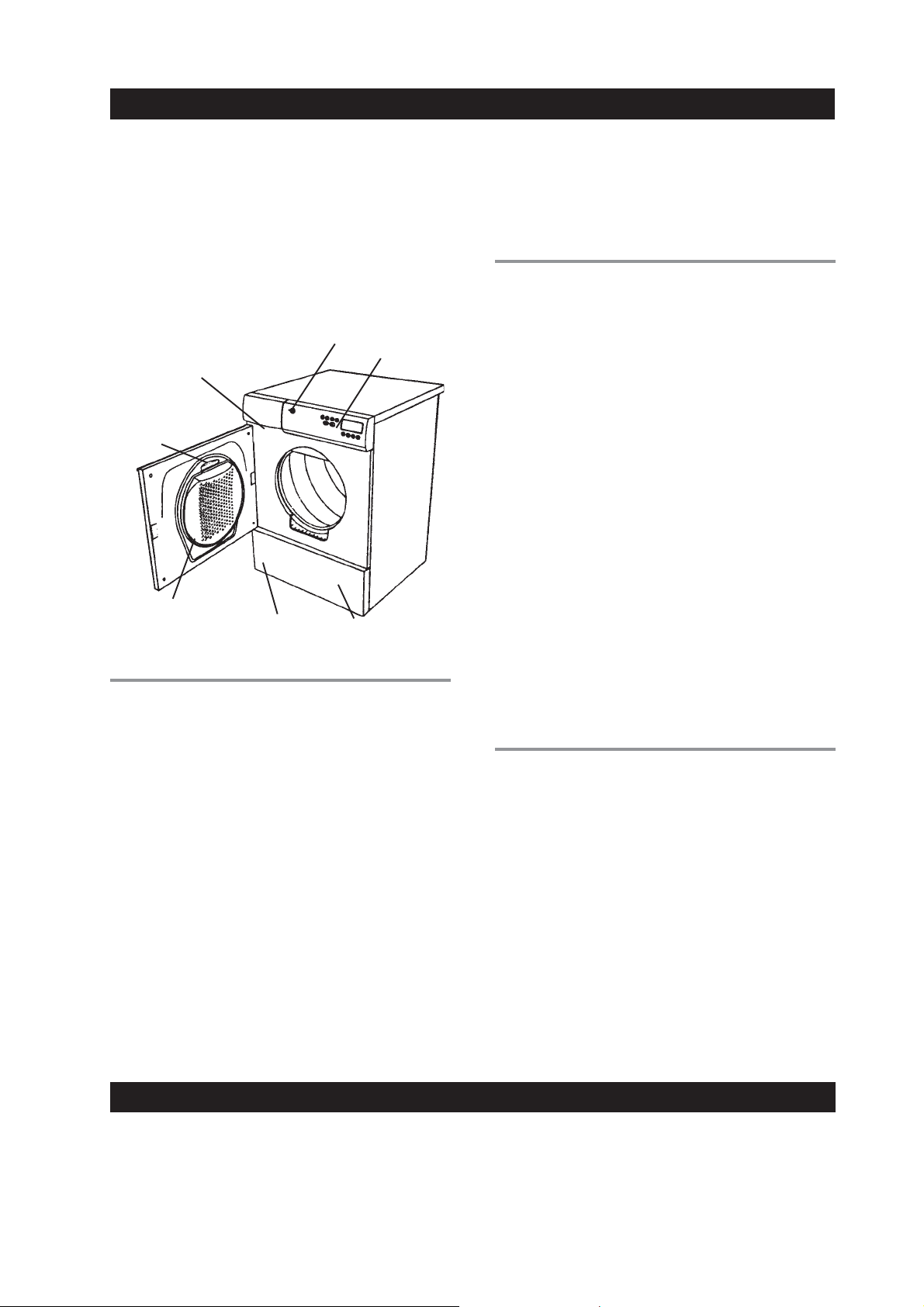
Below is an illustration of the parts and features of your
ASKO dryer.
Power
Button
Type Plate
(Type and Serial Number)
Lint Filter
Lint Filter
Holder
DRDR
YING SYYING SY
DR
YING SY
DRDR
YING SYYING SY
ASKO dryers come with three different drying systems:
Cleanable Fan
(behind panel)
STEMSSTEMS
STEMS
STEMSSTEMS
Control
Panel
Condenser Unit
(behind panel)
(T721 & T781 only)
Model T731 has timer-controlled drying in addition to
the four automatic programs.
When using a timed drying program, be careful not to
dry the clothes too long. It’s best to use a shorter time;
then if the load isn’t dry, you can set the timer for a few
more minutes.
OO
VERHEAVERHEA
O
VERHEA
OO
VERHEAVERHEA
ASKO dryers are designed with an overheat protection
switch that will automatically turn the machine off if the
temperature gets too high. The machine will not start
until it has cooled down sufficiently.
If the unit shuts down because of overheating, check
that the lint filter exhaust hose, vent duct, and the
condenser unit are free of lint. These components need
to be cleaned on a regular basis. Additionally, the lint
filter may need to be cleaned with warm, soapy water
and a soft brush a few times a year to ensure the filter
screen is not blocked. Using dryer sheets (not
recommended) can also cause this problem.
Should the machine turn itself off because of
overheating, it will not be possible to restart the unit
until it has cooled down sufficiently. This could possibly
take up to thirty minutes.
To restart the unit once it has cooled down, press the
“Start” button.
NOTE: If your dryer overheats frequently, it may not be
vented properly or the room in which it is located
may not have sufficient air circulation. Contact
your installer to have these issues checked out.
T PRT PR
T PR
T PRT PR
OO
TECTIONTECTION
O
TECTION
OO
TECTIONTECTION
ENGLISHENGLISH
ENGLISHENGLISH
ENGLISH
SensidrSensidr
Sensidr
SensidrSensidr
Models T731, T761 and T781 have our state-of-the-art
Sensidry system. These machines are equipped with a
humidity sensor that ensures different fabrics always
dry thoroughly. This sensor turns off the heat when the
laundry has reached the appropriate dryness.
TT
herher
T
her
TT
herher
Model T711 has a thermostat that controls the
temperature by turning the heating element on and off
to maintain the selected drying temperature (Normal or
Low) within +/- 5° F.
TimerTimer
Timer
TimerTimer
Model T711 has timer-controlled drying in addition to
the two automatic (thermostat-controlled) programs.
Model T721 offers only timed drying. You can set the
dryer to run from 30 minutes to 190 minutes.
ENERENER
ENER
ENERENER
♦ Dry consecutive loads to avoid reheating the dryer.
♦ Do not overload the dryer.
♦ Use the highest spin speeds allowed for the
garments.
♦ Do not put extremely wet clothes into the dryer.
y™y™
y™
y™y™
mostamosta
mosta
mostamosta
-Contr-Contr
-Contr
-Contr-Contr
GY SAGY SA
GY SA
GY SAGY SA
t-Contrt-Contr
t-Contr
t-Contrt-Contr
olol
ol
olol
VING VING
VING
VING VING
olol
ol
olol
TIPSTIPS
TIPS
TIPSTIPS
COCO
OL-DOWNOL-DOWN
CO
OL-DOWN
COCO
OL-DOWNOL-DOWN
Every program on an ASKO dryer ends with a cool-down
cycle to reduce wrinkling.
♦ Dry like fabrics together (i.e., heavy fabrics together,
light fabrics together).
♦ Clean the lint filter after each load.
♦ Do not over-dry clothes when using the timed program.
♦ Spin the clothes at no less than 800 rpm.
Page 3
Page 4
INSTINST
INST
INSTINST
ALLAALLA
ALLA
ALLAALLA
TION INSTRTION INSTR
TION INSTR
TION INSTRTION INSTR
UCTIONSUCTIONS
UCTIONS
UCTIONSUCTIONS
Read these instructions carefully and completely before
you install the machine. The installation should be
carried out by a qualified person who is familiar with all
local codes and ordinances for electrical and plumbing
connections.
SPECIFICASPECIFICA
SPECIFICA
SPECIFICASPECIFICA
Height 33-1/2”–34-1/2 (850–876 mm)
Width 23-7/16” (595 mm)
Depth T761/T781: 23-7/16" (595 mm)
Weight 86 lbs (39 kg)
Drum material Stainless Steel
CONNECTING CONNECTING
CONNECTING
CONNECTING CONNECTING
NOTE: You will need to purchase a UL-CSA-approved
4-inch ridged metal exhaust duct.
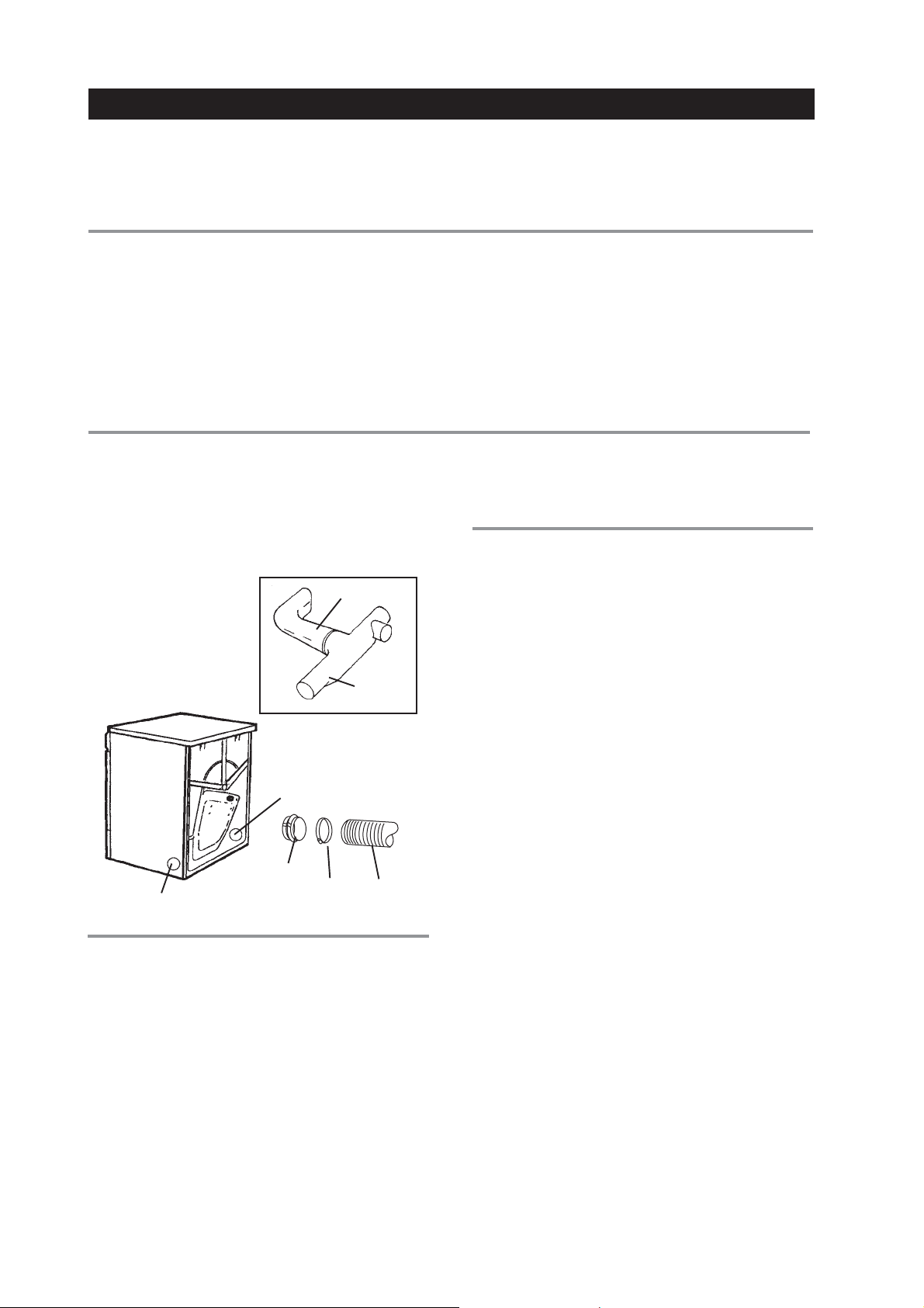
The dryer is delivered with the stub pipe attached to the
rear exhaust outlet, but the exhaust duct can be attached
to either the right or left exhaust outlet.
ASKO dryers have a
“T-style” exhaust vent
that allows you to
connect the duct on the
rear or on the left or
right side.
Side Exhaust Outlet
TIONSTIONS
TIONS
TIONSTIONS
Plus exhaust hose connection
T711/T721/T731: 24-7/16” (620 mm)
THE EXHATHE EXHA
THE EXHA
THE EXHATHE EXHA
Rear Exhaust Outlet
Stub
UST DUCT UST DUCT
UST DUCT
UST DUCT UST DUCT
Vent
T-Tube
Clamp Duct
(not supplied)
CONNECTING THE EXHAUST DUCT TO
THE REAR OUTLET
To connect the exhaust duct to the rear outlet, follow the
steps below:
1. Push the duct onto the stub pipe and secure it with a
clamp.
2. With the duct attached, insert the stub pipe into the
hole. It should snap into place.
3. After you push the dryer into place, check for kinks
in the duct.
NOTE: Excessive duct length and too many bends can
impede drying performance. We recommend
that you cut off any excess exhaust duct and
run the duct with as few bends as possible. Make
any necessary bends as gentle as possible.
NOTE: Cosmetic damage must be reported to your
dealer within five days from the date of purchase. After unpacking the dryer, thoroughly
check the unit for cosmetic damage.
Outer casing Stove-enamelled hot-dipped
galvanized steel
Power requirement 2800 watts (T711: 3300 watts)
For connection Single-phase, 230 V, 30 Amp
Internal fuse 15 amp. (T711: no fuses)
Heating element 2500 watts (T711: 3000 watts)
TT
O O
THE DRTHE DR
T
O
THE DR
TT
O O
THE DRTHE DR
NOTE: Maximum duct length of 22 feet is allowed.
Subtract 4 feet of duct for each 90° elbow.
YER YER
YER
YER YER
(T711/T731/T761)(T711/T731/T761)
(T711/T731/T761)
(T711/T731/T761)(T711/T731/T761)
CONNECTING THE EXHAUST DUCT TO
THE LEFT OR RIGHT SIDE OUTLET
To connect the exhaust duct to the left or right side outlet,
follow the steps below:
1. Using a flathead screw-driver, turn the exhaust outlet
cover you plan to use to the right or left to align the
tabs holding the cover in place.
2. Remove the exhaust outlet cover.
3. Remove the stub pipe from the rear exhaust outlet
and place it in the outlet you plan to use.
4. Push the duct onto the stub pipe and secure it with a
clamp.
5. With the duct attached, insert the stub pipe into the
hole. It should snap into place.
6. After you push the dryer into place, check for kinks
in the duct.
7. Use the exhaust outlet cover you removed from the
to cover the rear exhaust outlet.
WARNING!
To reduce the risk of fire, this appliance must be
exhausted OUTDOORS or the equivalent.
Never cover the end of the dryer stub or exhaust
duct with anything to catch lint, except for UL
approved vent basket.
Page 4
Page 5
CONNECTING CONNECTING
CONNECTING
CONNECTING CONNECTING
T
TT
TT
O O
O
O O
A A
VENTILAVENTILA
A
VENTILA
A A
VENTILAVENTILA
TION DUCT (T711/T731/T761)TION DUCT (T711/T731/T761)
TION DUCT (T711/T731/T761)
TION DUCT (T711/T731/T761)TION DUCT (T711/T731/T761)
You will need a UL-CSA-approved, 4-inch ridged metal
exhaust duct.
NOTE: The more bends and the longer the duct, the
less air will circulate through the machine,
which will impede drying performance. We recommend that you cut off any excess exhaust
duct and run the duct with as few bends as
possible. And make any necessary bends as
gentle as possible.
NOTE: Maximum duct length of 22 feet is allowed.
Subtract 4 feet of duct for each 90° elbow.
If more than 20 feet of duct is needed, the diameter
must be increased to 6” or 8” (152 mm or 203 mm).
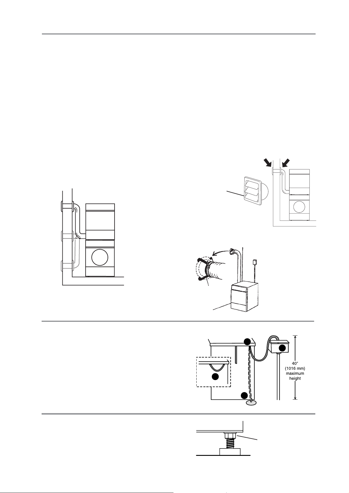
NOTE: When installing in warm climates (77° F and
above) with high humidity levels, do not
route the air exhaust duct upwards.
Installation Examples
Subtract 4 feet (122
cm) for every 90°
elbow.
To connect the exhaust duct to a ventilation outlet, follow
the steps below:
1. Connect the exhaust duct to a ventilation exhaust
fitting or to a discharge through the wall.
2. Secure the duct joint to the outlet stub on the machine.
3. Run the duct with as few bends as possible to the
point of discharge.
WARNING!
This appliance should not be exhausted into a chimney, a
wall, a ceiling, or a concealed space of a building. Only a
metal ventilation grill should be used.
If the duct is taken to a wall outlet, a ventilation grill
should be fitted to prevent reverse flow of cold air. Fit
the ventilation grill to the outside or inside of the wall.
Ventilation grill
Make sure nothing is blocking the
ventilation grill.
ENGLISHENGLISH
ENGLISHENGLISH
ENGLISH
CONDENSACONDENSA
CONDENSA
CONDENSACONDENSA
Install the dryer so the condensed water will
continuously flow into a drain or sink. To do this, follow
the instructions below:
1. Disconnect the short hose (1) from the blue
connection. (It’s okay to let the hose hang down.)
2. Connect the rubber hose supplied with the dryer to
the blue nipple (2).
3. Run the hose to a drain or sink, as illustrated.
NOTE: The drain hose must not be more than 40”
above the floor.
LEVELING LEVELING
LEVELING
LEVELING LEVELING
It is important that the machine is level. Each foot on
the dryer is adjustable, so you can level the unit on any
surface. Once it is level, securely tighten the lock nuts
on the feet.
TION DRAIN CONNECTION (T721 TION DRAIN CONNECTION (T721
TION DRAIN CONNECTION (T721
TION DRAIN CONNECTION (T721 TION DRAIN CONNECTION (T721
THE MATHE MA
THE MA
THE MATHE MA
CHINECHINE
CHINE
CHINECHINE
Vent spacer
AND AND
AND
AND AND
1
Back of dryer
T781)T781)
T781)
T781)T781)
2
3
If there is only one
vent duct from the
room, a vent spacer
must be fitted.
3
Be sure to tighten the lock
nuts securely when you
level the machine.
Page 5
Page 6
FREESTFREEST
FREEST
FREESTFREEST
The dryer can be placed next to the washing machine.
It is essential that the machine is leveled and the locknuts
are tight to eliminate vibration noise.
BB
UILUIL
B
UIL
BB
UILUIL
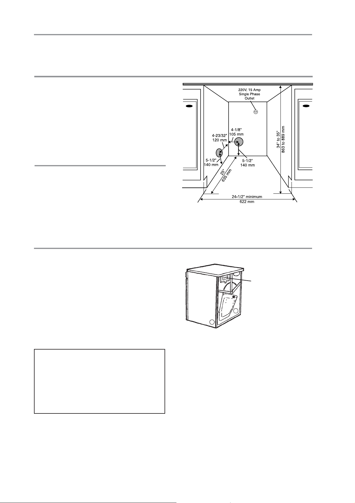
ASKO dryers can be installed beneath a cabinet or
worktop with a minimum height of 34” (864 mm). There
must be a gap of about 1/2” (12 mm) all around the
machine, including between the rear edge of the machine
top panel and the back wall. The opening width must be
at least 24-1/2” (622 mm).
Space must also be available for the exhaust hose on
the left, right or rear of the machine. See the diagram
for hole sizes and positions. Note that the hole
measurements are to the center of the hole.
CONDENSING DRYERS (T721/T781)
The condensing models work best when they have good
air circulation. Therefore, we don’t recommend they be
installed beneath a cabinet. If it is necessary, however,
be sure to leave a gap of at least 1/2” (12 mm) on all
sides.
Install the dryer so the condensed water will
continuously flow into a drain or sink, you will need a
drain outlet behind the unit. The maximum drain height
is 40” (1016 mm). (See page 4.)
ANDING INSTANDING INST
ANDING INST
ANDING INSTANDING INST
TT
-IN INST-IN INST
T
-IN INST
TT
-IN INST-IN INST
ALLAALLA
ALLA
ALLAALLA
ALLAALLA
ALLA
ALLAALLA
TIONTION
TION
TIONTION
TIONTION
TION
TIONTION
There should be at least 1/2” (12 mm) of space between
the washer and dryer.
NOTES: The height adjustment for the dryer is
33-1/2” to 34-1/2” (850 mm to 876 mm). Do
not raise it higher than 34-1/2”.
Hole measurements are from center of hole.
ELECTRICAL CONNECTIONSELECTRICAL CONNECTIONS
ELECTRICAL CONNECTIONS
ELECTRICAL CONNECTIONSELECTRICAL CONNECTIONS
WARNING!
This appliance must be properly grounded.
Refer to the “Important Safety Instructions” on
page 2 for grounding instructions.
The power supply cord must be grounded. If the
machine is to be used in a wet area, the supply must
be protected by a residual current device.
Connection to a permanently wired supply point must
be made only by a qualified electrician.
As supplied: Single-phase, 230 V, 60 Hz,
2500 Watt heater rating (T711: 3000 W)
30 A fuse required
WARNING:
The receptacle on the rear of the machine is
designed to accommodate ASKO washers ONLY
(rated 208–240 V.) To use this receptacle, you must
use the ready-fitted plug supplied with the washing
machine or an equivalent.
ASKO washers rated 208–240 V have two internal
fuses of 15 A each.
Remove cover to access
terminal box. (Requires a
20-Torx screwdriver.)
NOTE: In Canada, the dryer is delivered ready-fitted
with a four-prong plug intended for connection
to a single-phase supply.
Page 6
Page 7
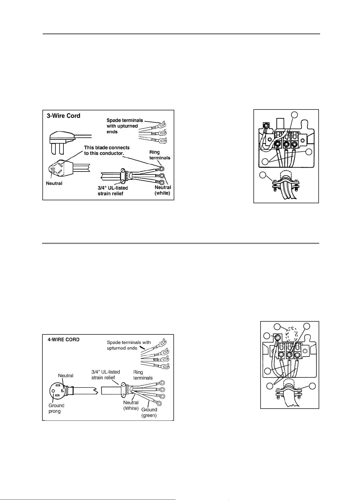
CONNECTING A 3-WIRE POWER CORD
WARNING!
Before starting this procedure, be sure the
power is turned off at the breaker/fuse box.
Power Supply Cord
You will need a 3-wire power supply cord with three No.
10 copper wires and a matching 3-wire receptacle of
NEMA Type 10-30R, as illustrated below:
To connect a 3-wire power cord to the dryer, follow the
steps below.
NOTE: The numbers in the illustration below corre-
late to the step numbers.
1. Turn the power off at the breaker/fuse box.
2. Remove terminal block cover.
3. Use the strain relief attached below the terminal
block opening.
4. Loosen or remove
center terminal
block screw.
5. Connect neutral
(white ) wire of
power supply cord
to the center, silvercolored terminal
screw. Tighten
screw.
6. Connect the other
wires to outer
screws.
7. Tighten the strain
relief screws.
8. Replace terminal box cover on back of dryer.
9. Plug dryer into wall receptacle.
10. Turn power on at breaker/fuse box.
6
7
4
5
ENGLISHENGLISH
ENGLISHENGLISH
ENGLISH
CONNECTING A 4-WIRE POWER CORD
WARNING!
Before starting this procedure, be sure the
power is turned off at the breaker/fuse box.
Power Supply Cord
You will need a 4-wire power supply cord with four No.
10 copper wires and a matching 4-wire receptacle of
NEMA Type 14-30R, as illustrated below. The fourth wire
must be identified with a green cover and the neutral
conductor by a white cover.
To connect a 3-wire power cord to the dryer, follow the
steps below.
NOTE: The numbers in the illustration below corre-
late to the step numbers.
1. Turn the power off at the breaker/fuse box.
2. Remove terminal block cover.
3. Use the strain relief attached below the terminal
block opening.
4. Remove center
terminal block screw.
5. Remove ground wire
(green with yellow
stripes) from external
ground connector
screw. Fasten under
center, silver-colored
terminal block screw.
6. Connect ground
(green) wire of cord to
external ground
conductor screw.
7. Connect neutral (white)
wire of cord under
center screw of terminal block.
8. Connect the other wires to outer screws.
9. Tighten the strain relief screws.
10. Replace terminal box cover on back of dryer.
11. Plug dryer into wall receptacle.
12. Turn power on at breaker/fuse box.
5
6
7
8
4
9
Page 7
Page 8
STST
AA
CKED INSTCKED INST
ST
A
CKED INST
STST
AA
CKED INSTCKED INST
ALLAALLA
ALLA
ALLAALLA
TIONTION
TION
TIONTION
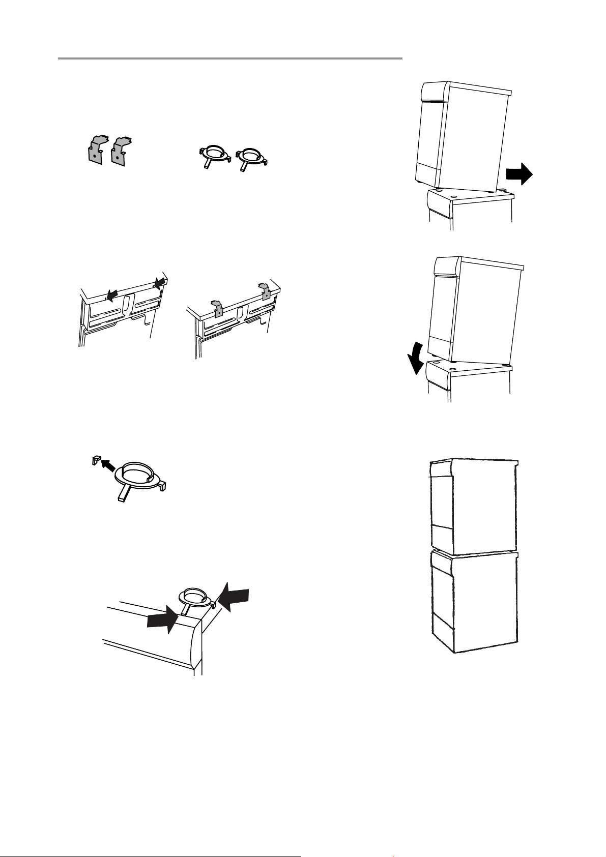
ASKO dryers can be mounted on top of any matching
ASKO washer. Mounts are supplied with the machine.
The metal brackets are attached to the lower back of
the unit. The plastic cups are packed inside the dryer.
Two metal brackets for
securing the dryer to the
washer
To install the dryer on top of the washer, follow the steps
below:
1. Remove the two outside screws (A) (20 torx) from
the back of the washer and use them to secure the
metal brackets (B), as illustrated below.
A
Washer back
2. To ensure the dryer is correctly positioned on top of
the washer, you will need to align the plastic cups
with the front top edge of the washer. To position the
plastic cups, break off the left tab on the cup to be
placed on the right side of the washer and break off
the right tab on the cup to be placed on the left side
of the washer.
Two plastic cups to
secure the dryer legs.
B
Washer back
5. Lift the dryer into
position. Raising the
front edge, push the
dryer backwards
until it engages with
the brackets on the
back of the washer.
6. Carefully lower
the front of the
dryer, making
sure the feet fit
into the plastic
cups.
StacStac
kk
Stac
k
StacStac
kk
ed Installaed Installa
ed Installa
ed Installaed Installa
tiontion
tion
tiontion
Plastic cups
3. Remove the protective paper from the self-adhesive
surface beneath the cups. Being careful not to press
the adhesive surface against the top of the washing
machine, use the tabs to position the cups (as
illustrated below) then press them firmly into place.
Washer front
4. Once the cups are correctly in place, break off the
remaining plastic tabs.
Tumble dryer
Washer
Total height 67”.
Adjustable to 69”.
WARNING!
Never stack a washer on top of a dryer!
Page 8
Page 9
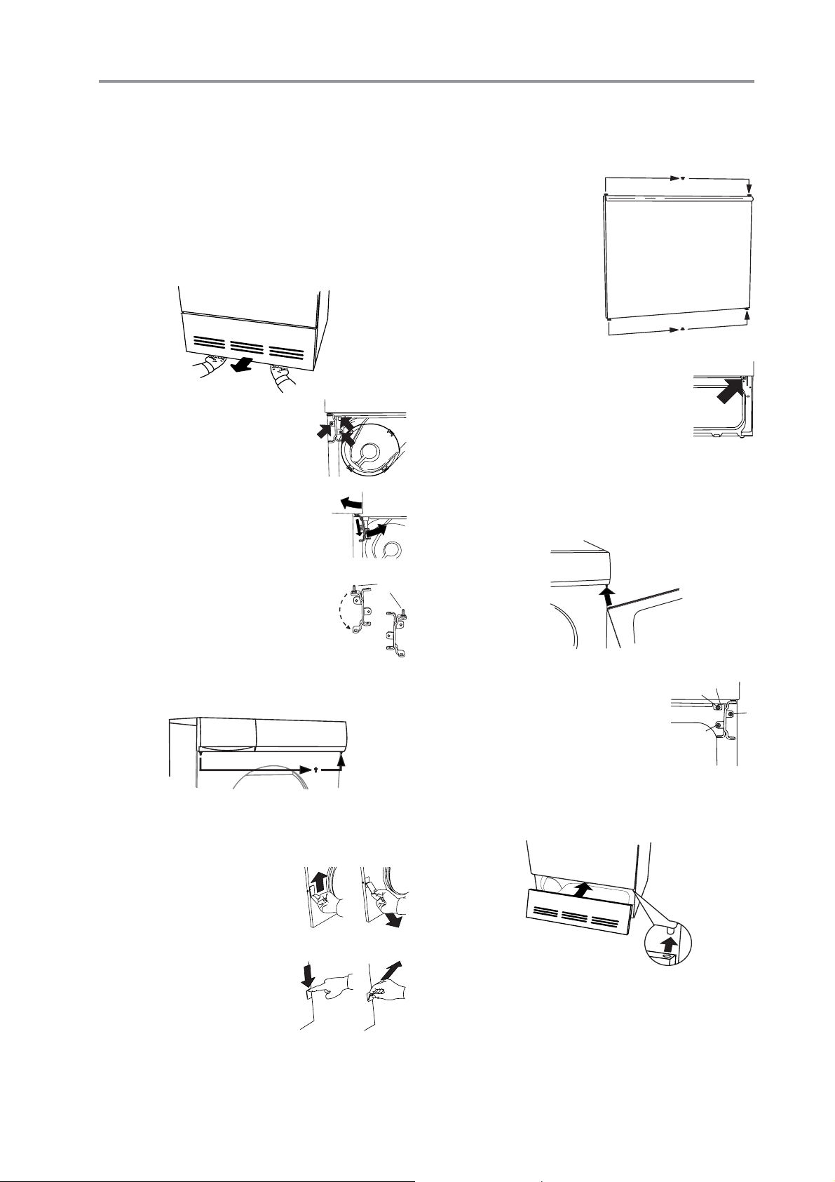
REVERSING THE DOOR HINGESREVERSING THE DOOR HINGES
REVERSING THE DOOR HINGES
REVERSING THE DOOR HINGESREVERSING THE DOOR HINGES
The door hinges on ASKO dryers are reversible. The
dryers are shipped left-hinged. To reverse them, follow
the steps below:
WARNING!
1. Remove the two 20 torx screws on the bottom of
the bottom panel then grasp the bottom of the panel
and pull it forward and down.
2. Remove the bottom hinge
bracket by removing the three
screws holding the bracket in
place.
3. Supporting the door from the
bottom, pull it out and to the left as
you turn the hinge bracket counterclockwise.
4. Remove the hinge pin at the top of
the hing bracket.
5. Turn the hinge bracket upside down
and put the hinge pin into the top hole.
Switch off the main power supply
before you start this procedure.
2
1
3
Hinge
pin
11. Tighten the screws on the sides of the doors to hold
the magnetic catch and cover plate in place.
12. Using a flathead
screwdriver, carefully
remove the plastic
plugs in the upper
and lower edge of the
door and place them
in the empty holes on
the opposite side.
13. Remove the screw in the top right
corner of the bottom panel. (If you
have a condenser dryer, you will have
to open the condenser unit door.)
14. Now you are ready to mount the door on the right
side. Holding the door at an angle (as illustrated),
fit the hinge pin into the top hole.
ENGLISHENGLISH
ENGLISHENGLISH
ENGLISH
6. Transfer the top hinge pin to the right side of the
dryer casing.
7. Loosen the two screws on both outer edges of the
door so you can remove the magnetic door catch
and the cover plate.
8. Remove the magnetic catch
by pushing it up then lifting it
out from the bottom.
9. Remove the cover plate on
the opposite side of the door
by pushing it down then lifting
it out from the top.
10. Reverse steps 8 and 9 to place the door catch and
cover plate into their new positions.
15. Position the bottom hinge bracket
and secure it with the screws in the
order illustrated at right (a, b, c).
16. Replace the screw you removed
in step 13 (d).
17. Replace the lower panel.
18. Turn back on the main power.
a
d
c
b
Page 9
Page 10

PREPPREP
PREP
PREPPREP
ARING ARING
ARING
ARING ARING
THE LATHE LA
THE LA
THE LATHE LA
UNDRUNDR
UNDR
UNDRUNDR
YY
Y
YY
With proper attention to how you prepare your laundry
items for washing and drying, your wardrobe and linens
will look like new for years.
SORSOR
TING TING
SOR
TING
SORSOR
TING TING
For best drying results, clothes should be sorted properly.
Most importantly, you should follow the care label
instructions (see next page).
Below are some suggestions on how to sort your laundry
for drying.
THE LATHE LA
THE LA
THE LATHE LA
UNDRUNDR
UNDR
UNDRUNDR
YY
Y
YY
♦ Permanent press items should be dried together. For
the most wrinkle-free results when drying permanent
press items, you should fill the machine only half
full. These items also should be removed promptly
from the dryer and hung up or folded right away.
♦ Dry heavy fabrics together and lightweight fabrics
together.
♦ Dry fabrics that shed lint (chenille, terry cloth, etc.)
separately from fabrics that collect lint (synthetics,
velveteen, corduroy, etc.).
♦ Separate non-colorfast fabrics from light-colored
items.
♦ If the care label says "Wash Separately," the fabric
is likely to lose color (excess dye) for the first few
washings. To minimize the possibility of the dye
transferring to white or lighter colored items, dry new
colored garments with items of similar color or alone.
Bright reds and oranges on cottons are the dyes most
likely to transfer colors.
NOTE: Refer to “Important Safety Instructions” on page
2 for a list of specific materials that should never
be put in a tumble dryer.
DRDR
YING YING
DR
YING
DRDR
YING YING
Drying times will vary due to the amount of laundry in
the machine, moisture content, type of fabric, air
temperature and humidity. The length of the vent hose
can also affect drying times. (See “Connecting to a
Ventilation Duct” on page 5 for the recommended
installation.)
GENERAL LAGENERAL LA
GENERAL LA
GENERAL LAGENERAL LA
♦
Read all recommended care labels carefully. If the
care label says “Drip dry,” “Line dry” or Dry flat,” do
not dry that item in the dryer. Certain fabrics will
melt or become dangerously flammable if heated,
while others may lose their shape.
TIMESTIMES
TIMES
TIMESTIMES
UNDRUNDR
UNDR
UNDRUNDR
Y Y
Y
Y Y
ADAD
AD
ADAD
VICEVICE
VICE
VICEVICE
♦ Remove any sharp ornaments, pins or buckles to
prevent snags.
♦ Empty pockets and turn them inside out.
♦ Close zippers and hooks to prevent snagging.
♦ Tie sashes and strings to prevent tangling.
♦ Mend any small rips to prevent them from enlarging.
♦ Turn colored cotton garments, velvet and finer
knitwear inside out before washing.
♦ Turn delicate items, sweaters and T-shirts inside out
to prevent pilling and to protect the prints.
♦ Prewash severely soiled items.
♦ Wash and dry colored fabrics separately the first
time.
♦ Thoroughly rinse down items, such as comforters
(Super rinse).
♦ Use fabric softener to eliminate static electricity in
synthetic garments and to soften cotton.
FF
ABRIC SOFTENER SHEETSABRIC SOFTENER SHEETS
F
ABRIC SOFTENER SHEETS
FF
ABRIC SOFTENER SHEETSABRIC SOFTENER SHEETS
We recommend that you do not use fabric softener
sheets in the dryer. Over time, the chemicals on these
sheets can build up inside the lint filter and clog the
holes that circulate the air.
RECOMMENDED RECOMMENDED
RECOMMENDED
RECOMMENDED RECOMMENDED
Different fabrics require different load sizes and drying
temperatures. The table below gives recommended
* Always refer to the care label on the garment to determine if it can be tumble dried. (See
page 11.) Some wool and silk and hand-washable items should not be tumble dried.
These items should be removed from the washer then pressed out in a terry towel to
remove excess water before being hung up or laid flat to dry.
TEMPERATEMPERA
TEMPERA
TEMPERATEMPERA
Fabric Type Setting Size
Cotton w/out elastic and/or decorative trim Normal Full
Linen – white and colorfast Normal Half
Cotton/polyester blends Low Half
Polyester/acrylic blends Low Half
Rayon and acetate Low Half
Washable silk and nylon * Low Third
TURE SETTINGS TURE SETTINGS
TURE SETTINGS
TURE SETTINGS TURE SETTINGS
AND LOAND LO
AND LO
AND LOAND LO
temperature settings and load sizes for different fabrics.
Temp Load
AD SIZESAD SIZES
AD SIZES
AD SIZESAD SIZES
Page 10
Page 11

CARE LABEL INSTRCARE LABEL INSTR
CARE LABEL INSTR
CARE LABEL INSTRCARE LABEL INSTR
Most clothes and other washable items have
recommended care labels. Read these labels carefully!
Care label instructions and warnings should be followed
for the best cleaning results.
The table below defines the symbols used on fabric care
labels. (NOTE: Some manufacturers may use slightly
different symbols.)
UCTIONSUCTIONS
UCTIONS
UCTIONSUCTIONS
CARE LABEL SYMBOLSCARE LABEL SYMBOLS
CARE LABEL SYMBOLS
CARE LABEL SYMBOLSCARE LABEL SYMBOLS
As an example, the symbols in the label illustrated below
mean: wash in warm water on permanent press setting.
Use non-chlorine bleach. Dry on permanent press setting.
Iron on low temperature setting.
ENGLISHENGLISH
ENGLISHENGLISH
ENGLISH
Page 11
Page 12

T711 OPERAT711 OPERA
T711 OPERA
T711 OPERAT711 OPERA
WARNING! To reduce the risk of electric shock or injury to persons, read the ”Important Safety
Instructions” section on page 2 before operating this appliance.
TING INSTRTING INSTR
TING INSTR
TING INSTRTING INSTR
UCTIONSUCTIONS
UCTIONS
UCTIONSUCTIONS
THE CONTRTHE CONTR
THE CONTR
THE CONTRTHE CONTR
Power Button
Turns power to the
machine off and on.
Power Indicator Light
Glows when the power is
turned on.
Signal Button
Turns the end-ofprogram signal off
and on.
POWER BUTTONPOWER BUTTON
POWER BUTTON
POWER BUTTONPOWER BUTTON
The Power button turns the power to the machine on
and off. When the power is on, the power indicator light
glows red. The power must be on before you can start
the machine.
STST
ARAR
ST
STST
This button starts the dryer. If you open the door during
a program, the dryer will stop tumbling automatically.
To continue the program, close the door and press Start.
PRPR
PR
PRPR
This model has two preset programs:
Heavy – for heavy items, such as jeans or thick towels
T BUTTT BUTT
AR
T BUTT
ARAR
T BUTTT BUTT
OGRAM CONTROGRAM CONTR
OGRAM CONTR
OGRAM CONTROGRAM CONTR
OL POL P
ANELANEL
OL P
ANEL
OL POL P
ANELANEL
Power Signal
Wrinkle-free Button
Turns the wrinkle-free
cycle on and off.
ONON
ON
ONON
OLOL
OL
OLOL
Start Button
Press to start a
program.
Wrinkle
Cool-down Start
free
Cool-down Button
Lets you select a 3-minute or
18-minute cool-down cycle.
Temperature/Air Fluff Control
Turn to select Normal or Low drying
temperatures or the Air Fluff program.
Temperature Programs
Normal
Air fluff
Low
Air fluff
Timed dry:
30 min
60 min
90 min
Program Control
Turn to select an automatic program
or timed drying.
Heavy
Normal
Low
This temperature setting should be used for lighter,
more delicate fabrics, such as synthetics, permanent
press, acrylics, etc.
Air Fluff
This setting does not activate the heating element. It
simply circulates the air as the clothes tumble to shake
out the dust and refresh the clothes.
OPTIONSOPTIONS
OPTIONS
OPTIONSOPTIONS
Signal
When this button is depressed (on), a signal will sound
for three seconds when the program is complete.
Note: The Cool-down button must also be pressed in
for the signal to sound.
Normal – for cottons, permanent press, synthetics, etc.
These programs work with a thermostat that measures
the exhaust temperature coming out of the dryer and
automatically turns the machine off when the clothes
are appropriately dry.
Timed Drying (30, 60 or 90 minutes)
If you prefer, you can set the Program Control knob to a
specific number of minutes to dry the laundry. When
you choose timed drying, you must set the Temperature
Control knob to Normal or Low.
Air Fluff Program
The Air Fluff program is designed to shake dust out of
fabrics, air them, or soften them. This program does
not activate the heating element.
TEMPERATEMPERA
TEMPERA
TEMPERATEMPERA
TURE CONTRTURE CONTR
TURE CONTR
TURE CONTRTURE CONTR
OLOL
OL
OLOL
Normal
This temperature setting should be used for heavier
fabrics, such as denim, cotton, linen, etc.
Page 12
Wrinkle-free
The Wrinkle-free option prevents garments from
wrinkling if you’re unable to remove them right away.
When this button is depressed (on), the drum will
continue to rotate for three seconds every minute after
they drying program is complete, until the door is opened
or one hour has passed. If the signal is on, it will sound
each time the wrinkle-free program activates.
Cool-down
When this button is depressed (on), the cool-down time
is increased from 3 minutes to 18 minutes. This option
can not be selected with the Anti-crease option.
INTERRINTERR
INTERR
INTERRINTERR
CANCELLING A PROGRAMCANCELLING A PROGRAM
CANCELLING A PROGRAM
CANCELLING A PROGRAMCANCELLING A PROGRAM
To interrupt a program, simply open the door. The dryer
will stop tumbling automatically. To continue the
program, close the door and press Start. The program
will continue from the point it was interrupted.
To cancel a program, press the Power button to turn off
the power or turn the Program Control knob clockwise
until the dryer stops.
UPTING ORUPTING OR
UPTING OR
UPTING ORUPTING OR
Page 13

T721 OPERAT721 OPERA
T721 OPERA
T721 OPERAT721 OPERA
WARNING! To reduce the risk of electric shock or injury to persons, read the ”Important Safety
Instructions” section on page 2 before operating this appliance.
TING INSTRTING INSTR
TING INSTR
TING INSTRTING INSTR
UCTIONSUCTIONS
UCTIONS
UCTIONSUCTIONS
THE CONTRTHE CONTR
THE CONTR
THE CONTRTHE CONTR
Power Button
Turns power to the
machine off and on.
Power Indicator Light
Glows when the power is
turned on.
Signal Button
Turns the end-ofprogram signal off
and on.
POWER BUTTONPOWER BUTTON
POWER BUTTON
POWER BUTTONPOWER BUTTON
The Power button turns the power to the machine on
and off. When the power is on, the power indicator light
glows red. The power must be on before you can start
the machine.
STST
ARAR
ST
STST
Press this button to start the dryer. If you open the door
during a program, the dryer will stop tumbling
automatically. To continue the program, close the door
and press Start.
TIMER CONTRTIMER CONTR
TIMER CONTR
TIMER CONTRTIMER CONTR
Use this knob to set the number of minutes you want to
dry the laundry.
T BUTTT BUTT
AR
T BUTT
ARAR
T BUTTT BUTT
OL POL P
OL P
ANELANEL
ANEL
OL POL P
ANELANEL
ONON
ON
ONON
OL KNOBOL KNOB
OL KNOB
OL KNOBOL KNOB
Start Button
Press to start a
program.
Power Signal
Wrinkle-free Button
Turns the wrinkle-free
cycle on and off.
Wrinkle
free
Cool-down Start
Air Fluff Program
The Air Fluff program is designed to shake dust out of
fabrics, air them, or soften them.
Temperature/Air Fluff Control
Turn to select Normal or Low drying temperatures or
the Air Fluff program.
Temperature Programs
Normal
Air fluff
Cool-down Button
Lets you select a 9-minute or
18-minute cool-down cycle.
OPTIONSOPTIONS
OPTIONS
OPTIONSOPTIONS
Low
Air fluff
Timer Control
Turn to set the
drying time.
Timed dry:
180 min
150 min
120 min
90 min
60 min
30 min
Signal
When this button is depressed (on), a signal will sound
for three seconds when the program is complete.
Note: The Cool-down button must also be pressed in
for the signal to sound.
Wrinkle-free
The Wrinkle-free option prevents garments from
wrinkling if you’re unable to remove them right away.
When this button is depressed (on), the drum will
continue to rotate for three seconds every minute after
they drying program is complete, until the door is opened
or one hour has passed. If the signalis on, it will sound
each time the wrinkle-free program activates.
Cool-down
When this button is depressed (on), the cool-down time
is increased from 9 minutes to 18 minutes. This option
cannot be selected with the Wrinkle-free option.
ENGLISHENGLISH
ENGLISHENGLISH
ENGLISH
TEMPERATEMPERA
TEMPERA
TEMPERATEMPERA
TURE CONTRTURE CONTR
TURE CONTR
TURE CONTRTURE CONTR
OLOL
OL
OLOL
Normal
This temperature setting should be used for heavier
fabrics, such as denim, cotton, linen, etc.
Low
This temperature setting should be used for lighter,
more delicate fabrics, such as synthetics, permanent
press, acrylics, etc.
Air Fluff
This setting does not activate the heating element. It
simply circulates the air as the clothes tumble to shake
out the dust and refresh the clothes.
INTERRINTERR
INTERR
INTERRINTERR
CANCELLING A PROGRAMCANCELLING A PROGRAM
CANCELLING A PROGRAM
CANCELLING A PROGRAMCANCELLING A PROGRAM
To interrupt a program, simply open the door. The dryer
will stop tumbling automatically. To continue the
program, close the door and press Start. The program
will continue from the point it was interrupted.
To cancel a program, press the Power button to turn off
the power or turn the Timer Control knob clockwise until
the dryer stops.
UPTING ORUPTING OR
UPTING OR
UPTING ORUPTING OR
Page 13
Page 14

T731 OPERAT731 OPERA
T731 OPERA
T731 OPERAT731 OPERA
WARNING! To reduce the risk of electric shock or injury to persons, read the ”Important Safety
Instructions” section on page 2 before operating this appliance.
TING INSTRTING INSTR
TING INSTR
TING INSTRTING INSTR
UCTIONSUCTIONS
UCTIONS
UCTIONSUCTIONS
THE CONTRTHE CONTR
THE CONTR
THE CONTRTHE CONTR
Power Button
Turns power to
the machine on
and off.
Power Indicator
Light
Glows when the
power is turned on.
POPO
WER BUTTWER BUTT
PO
WER BUTT
POPO
WER BUTTWER BUTT
The Power button turns the power to the machine on
and off. When the power is on, the power indicator light
glows red. The power must be on before you can start
the machine.
PRPR
OGRAM KNOBOGRAM KNOB
PR
OGRAM KNOB
PRPR
OGRAM KNOBOGRAM KNOB
Turn this knob to select a program. The programs are
described on the following page.
12:00 Position – This is where the line on the knob
aligns with the line above the knob. When the knob is in
this position, “00” displays on the LED to indicate no
program has been chosen.
STST
ARAR
ST
STST
After you have selected a program and the desired
options, press this button to start the dryer. The red
indicator light next to the Start button will come on. The
indicator light will go off when the program ends or has
been cancelled.
STST
ST
STST
You can stop or cancel a program by pressing and
holding the Stop button until the dryer stops. When you
press Start, the program will start from the beginning.
T BUTTT BUTT
AR
T BUTT
ARAR
T BUTTT BUTT
OP BOP B
OP B
OP BOP B
UTTUTT
UTT
UTTUTT
OL POL P
OL P
ONON
ON
ONON
ANELANEL
ANEL
OL POL P
ANELANEL
Power
Time set
Wrinkle free
Delay
Temperature
Signal
Quick cool-down
Program Knob
Turn to select a program.
ONON
ON
ONON
ONON
ON
ONON
Iron dry
Timed dry
Air fluff
LED Window
Displays program number, dry time
selected, remaining program time, etc.
Programs
until the Stop indicator light goes off (approximately 3
seconds). You will have to reselect a program and press
Start to restart the dryer.
LED WINDOWLED WINDOW
LED WINDOW
LED WINDOWLED WINDOW
The LED window displays the program number for the
Sensidry programs, as illustrated below:
Heavy
Normal
Delicate
Option Buttons
Press to select a
program option.
Start Button
Press to start a
program.
Stop Button
Press to stop a
program.
P1
The corresponding program numbers are:
Heavy = P1 Delicate = P3
Normal = P2 Iron Dry = P4
When you select Timed Dry, the LED displays the
number of minutes selected, plus the cool-down time,
as illustrated below:
20
When you select Air Fluff, the LED displays the number
of minutes selected, as illustrated above. With both
programs 5 and 6, as the program advances, the LED
displays the remaining time.
“End” on the LED indicates the program is complete.
“C” indicates the program is in the cool-down cycle.
INTERRINTERR
INTERR
INTERRINTERR
A PRA PR
A PR
A PRA PR
To interrupt a program, simply open the door. The dryer
will stop tumbling automatically. To continue the
program, close the door and press Start. The program
will continue from the point it was interrupted.
To cancel a program, press and hold the Stop button
Page 14
UPTING OR CANCELLINGUPTING OR CANCELLING
UPTING OR CANCELLING
UPTING OR CANCELLINGUPTING OR CANCELLING
OGRAMOGRAM
OGRAM
OGRAMOGRAM
Page 15

PRPR
OGRAMSOGRAMS
PR
OGRAMS
PRPR
OGRAMSOGRAMS
Your ASKO dryer has our state-of-the-art Sensidry
system. This means it has a humidity sensor that
ensures different fabrics always dry thoroughly. This
sensor turns off the heat when the laundry has reached
the appropriate dryness.
The Heavy, Normal, Delicate and Iron Dry programs
are automatic (Sensidry) programs designed for certain
types of loads, as defined in the table below. The sensor
detects different levels of humidity with each program.
It is important, therefore, to select the appropiate
program for the type of load you are drying.
If you prefer, you can select Timed Dry, which does not
activate the humidity sensor. You should be careful
when using this option not to overdry the fabrics. This
program automatically uses the Low temperature
setting, but you can change it to Normal by depressing
the Temperature button.
When using Timed Dry, it’s best to use a shorter time;
then if the load isn’t dry, you can set the timer for a few
more minutes.
NOTE: Always follow the care label instruction.
Program Definition
Heavy (P1) For items that are extremely difficult to dry, such as jeans and thick towels.
Normal (P2) Cotton w/out elastic and/or decorative trim.
Delicate (P3) Cotton with elastic and/or decorative trim, linen (white and colorfast).
Iron dry (P4) Synthetics, polyester, cotton/polyester blends.
Timed Dry Any fabric that can be machine dried. (See note below.)
Air Fluff This setting does not heat. It simply circulates the air as the clothes tumble to shake out
the dust and refresh the clothes. (See note below.)
NOTE: When using Timed Dry and Air Fluff, you must set the number of minutes for the program to run. (See “Time”
in the “Option Buttons” section below for details.)
ENGLISHENGLISH
ENGLISHENGLISH
ENGLISH
OPTION BOPTION B
OPTION B
OPTION BOPTION B
The option buttons allow you to select program time,
normal or low temperature, anti-crease, delayed start,
buzzer and quick cooling. Each of these options is
defined in more detail in the following paragraphs.
UTTUTT
UTT
UTTUTT
ONSONS
ONS
ONSONS
TIME SET
If you set the program knob to Timed Dry or Air Fluff, you
must select the length of drying time by pressing this
button until the number of minutes you wish to dry the
load displays on the LED. The time advances in 5minute increments and you can select between 5 and
90 minutes. If you pass the time you wanted to select,
continue to press the button until the correct time
displays.
WRINKLE-FREE
The Wrinkle-free option prevents garments from
wrinkling if you’re unable to remove them right away.
You can select one, two, or three hours by pressing the
Wrinkle-free button until the number of hours you prefer
displays, as illustrated below:
1h
DELAY
This option lets you set the dryer to start at the most
convenient time. This feature is also useful in areas
where utility companies offer discount rates during offpeak hours. You can set delayed start from 1 hour to 24
hours, in one-hour increments.
To set a delayed start time, press the button until the
number of hours you wish to delay starting the machine
displays on the LED, as illustrated below:
1h
If you pass the time you wanted to select, continue to
press the button until the correct time displays. If you
decide not to delay starting the unit, continue to press
the button until “0” displays.
Press Start and the unit will start after the number of
hours you selected has passed.
To cancel Delay Start after you have pressed the Start
button, press and hold the Stop button until the LED
displays the program number or, if the program knob is
set on 5 or 6, the number of minutes. You can then
press Start and the unit will start right then.
NOTE: “0” on the LED indicates the option is not active.
When you set a time, the drum will continue to rotate
after the program is complete for three seconds every
minute until the door is opened or the selected time (1–
3 hours) has passed. If the buzzer is on, it will sound
each time the anti-crease program activates.
TEMPERATURE
You have two temperature options: Normal and Low.
The Normal setting should be used for heavier fabrics,
such as denim, cotton, linen, etc. The Low setting should
be used for lighter, more delicate fabrics, such as
synthetics, permanent press, acrylics, etc.
The indicator light will stay lit when Low is selected. It
will remain off when Normal is selected.
Page 15
Page 16

SIGNAL
Press this button to set a signal to sound for three
seconds when a program is complete. The indicator
light will stay lit when this option is on.
If you selected the Wrinkle-free option, the signal will
sound every time the drum rotates.
PRPR
OGRAM MEMOROGRAM MEMOR
PR
OGRAM MEMOR
PRPR
OGRAM MEMOROGRAM MEMOR
The dryer is designed to retain the settings last selected
with each program. For example, if you select Normal,
the Low temperature option, a 2-hour anti-crease, and
Quick cool-down, next time you select Normal these
options will automatically be selected.
YY
Y
YY
CHILD-SAFE STCHILD-SAFE ST
CHILD-SAFE ST
QUICK COOL-DOWN
Every program, except Air Fluff, ends with a cool-down
cycle that tumbles the clothes without heat to reduce
wrinkling. The Cool-down button lets you choose
between the Normal cool-down cycle (15 minutes) or a
Quick cool-down cycle (5 minutes). The indicator light
will stay lit when Quick is selected.
CHANGING OPTION SETTINGSCHANGING OPTION SETTINGS
CHANGING OPTION SETTINGS
CHANGING OPTION SETTINGSCHANGING OPTION SETTINGS
You cannot change the option settings after you have
pressed Start. To change a setting, hold down the Stop
button until the unit stops, make your change, then press
Start again. The program will restart from the beginning.
T731 ERRT731 ERR
T731 ERR
T731 ERRT731 ERR
Error messages will display on the LED if a fault occurs
while a program is in progress. The table below defines
each possible error message. If the message still
MESSAGE ERROR
F1 Call a service technician.
F2 There may have been a power outage. Check the breaker box and fuses.
F3 This indicates a thermistor fault. Call a service technician.
F4 This indicates the overheat protection device has activated. Clean the lint filter and try running
F5 This indicates a fault in the moisture sensor. Running a dry program with dry clothes or an
OR MESSAOR MESSA
OR MESSA
OR MESSAOR MESSA
The dryer is programmed to stop after a maximum of 3 hours drying time. If it has run this long,
let it cool and try to start the program again.
Try turning the power off then on again. If the message remains, call a service technician.
the program again.
empty machine could also cause this error. Try opening the door. If the message remains, call a
service technician.
GESGES
GES
GESGES
CHILD-SAFE STCHILD-SAFE ST
You can program the dryer not to start unless the Start
button is held down for three seconds. This is to prevent
children from inadvertently starting the machine. To
program this function, follow the steps below:
1. Turn the machine off then on again. (“00” should show
on the LED.)
2. Press the Start button five times in succession then
press the Wrinkle-free button five times. (This must
be done within 15 seconds.)
3. Within three seconds, press the Wrinkle-free button
again to select Child-safe start. The LED will display
“3” to indicate the Child-safe start is active. (If the
child-safe start has already been activated, “0” will
display after you press the Wrinkle-free button.)
displays after you have checked the possible solutions,
call a service technician.
ARAR
AR
ARAR
T FEAT FEA
T FEA
T FEAT FEA
TURETURE
TURE
TURETURE
Page 16
Page 17

T761 T761
T761
T761 T761
WARNING! To reduce the risk of electric shock or injury to persons, read the ”Important Safety
Instructions” section on page 2 before operating this appliance.
AND AND
AND
AND AND
T781 OPERAT781 OPERA
T781 OPERA
T781 OPERAT781 OPERA
TING INSTRTING INSTR
TING INSTR
TING INSTRTING INSTR
UCTIONSUCTIONS
UCTIONS
UCTIONSUCTIONS
THE CONTRTHE CONTR
THE CONTR
THE CONTRTHE CONTR
Power Button
Press to turn power to
the machine on and off.
Power Indicator Light
Glows when the power is
turned on.
POPO
WER BUTTWER BUTT
PO
WER BUTT
POPO
WER BUTTWER BUTT
The Power button turns the power to the machine on
and off. When the power is on, the power indicator light
glows red. The power must be on before you can set
the programs or start the machine.
STST
ARAR
ST
STST
Once you have selected a program (P1–P4) and set the
desired options, press this button to start the dryer.
T BUTTT BUTT
AR
T BUTT
ARAR
T BUTTT BUTT
OL POL P
OL POL P
ONON
ON
ONON
ONON
ON
ONON
ANELANEL
ANEL
ANELANEL
OL P
Start Button
Press to start a
program.
Preset Programs
Press one of these buttons
to select a program.
P1 P2 P3 P4
Stop Button
Press to stop a
program.
LCD Window
Displays the program, temperature
settings, and program run time.
Start Stop
Program Selection Controls
These buttons allow you to customize the preset
program settings, such as temperature settings,
turning the buzzer off, setting delay start time, etc.
INTERRINTERR
INTERR
INTERRINTERR
A PRA PR
A PR
A PRA PR
To interrupt a program, simply open the door. The dryer
will stop tumbling automatically. To continue the
program, close the door and press Start. The program
will continue from the point it was interrupted.
To cancel a program, press and hold the Stop button
until the dryer stops (about three seconds). To restart
the dryer, you will have to reselect a program and press
Start.
UPTING OR CANCELLINGUPTING OR CANCELLING
UPTING OR CANCELLING
UPTING OR CANCELLINGUPTING OR CANCELLING
OGRAMOGRAM
OGRAM
OGRAMOGRAM
ENGLISHENGLISH
ENGLISHENGLISH
ENGLISH
STST
OP BUTTOP BUTT
ST
OP BUTT
STST
OP BUTTOP BUTT
You can stop or cancel a program by pressing Stop until
the dryer stops (about three seconds). If you stop the
dryer this way, it cancels the program in progress.
UNDERSTUNDERST
UNDERST
UNDERSTUNDERST
The LCD window is easy to read and understand. The
illustration below explains each item on the LCD window.
The LCD window also displays the menus and options
Program
When you press the Power button,
the display toggles between the
program numbers and the program
names, (e.g., Extra Dry, Dry, etc.)
Preset Programs
Displays the program that is
selected/running.
ONON
ON
ONON
ANDING ANDING
ANDING
ANDING ANDING
THE LTHE L
THE L
THE LTHE L
CD CD
WINDOWINDO
CD
WINDO
CD CD
WINDOWINDO
P1 Extra Dry
P2 Dry
P3 Normal Dry
P4 Iron Dry
Start
Indicates that you pressed Start and
the program is running.
WW
W
WW
available when you customize the preset programs (see
page 18).
Program Time
When you start a program, the total
time the program runs is displayed.
As the program progresses, the time
remaining displays. The program
time toggles between minutes (e.g.,
23) and hours (e.g., 1h).
Stop
Indicates that the program has ended
or that you pressed Stop.
Page 17
Page 18

THE PRESET PRTHE PRESET PR
THE PRESET PR
THE PRESET PRTHE PRESET PR
ASKO dryers are delivered with the four most commonly used programs. The table below lists the preset programs
and the settings for each. To select a program, simply press one of the program buttons and press Start. For
additional programming options, refer to “Customizing the Preset Program Buttons” below.
With ASKO’s Sensidry™ system, you need never worry about over-drying your laundry. Just select the proper program
for the type of fabric you’re drying and Sensidry does the rest. Once you select a program, Sensidry monitors the
temperature and measures the humidity level. When it detects the appropriate measurements, it automatically shuts
off the machine.
Preset Dry Cooling Anti Program Dry Cycle Temp Time Buzzer Crease
P1 Heavy Normal Quick
P2 Normal Normal Quick On 1 hr.
P3 Delicate Normal Quick On 1 hr.
P4 Iron Dry Low
OGRAMSOGRAMS
OGRAMS
OGRAMSOGRAMS
(1)
(2)
Quick On 1 hr.
On 1 hr.
NOTES:
WARNING!
CUSTCUST
CUST
CUSTCUST
In addition to the preset programs listed above, you can customize the preset buttons to use any of the programs listed
in the table below. This table also lists the pre-programmed settings for each program. For example, if you select
Normal dry on the program menu, it is automatically programmed to dry at the low temperature, cool-down for 15
minutes (normal time), run the anti-crease cycle for one hour, and set off the buzzer when the program ends. You can
modify some of these settings. (See “Dry Program Options” below.)
OMIZING OMIZING
OMIZING
OMIZING OMIZING
(1) The Quick cooling time is 5 minutes.
(2) On Model T781, the dry temperature for program P4 is Normal.
Some fabrics may not be able to withstand extremely hot temperatures. Always refer to the
garment care label to recommended wash temperatures.
THE PRESET PRTHE PRESET PR
THE PRESET PR
THE PRESET PRTHE PRESET PR
OGRAM BOGRAM B
OGRAM B
OGRAM BOGRAM B
UTTUTT
UTT
UTTUTT
ONSONS
ONS
ONSONS
AVAILABLE PROGRAMS
Program Dry Temp Cooling Time Anti-Crease Buzzer
Heavy Normal 15 minutes 1 hour On
Normal Normal 15 minutes 1 hour On
Delicate Low 15 minutes 1 hour On
Iron Dry Low 15 minutes 1 hour On
Air fluff n/a n/a 1 hour On
Timed dry Low 15 minutes 1 hour On
PROGRAM OPTIONS
The table below defines the program options. The next table lists all of the programs on the Program menu as well as
the settings and options available with each.
OPTION DEFINITIONS
Options Definitions
Quick
Cool-down
Signal If this option is on, a signal sounds for 3 seconds at the end of the program.
Wrinkle-free This option is designed to prevent wrinkling if you’re unable to remove them from the dryer
Temperature You have three temperature options: Normal, Low, and Air Fluff. Normal is for heavier fabrics,
Delay You can set a delayed start from 1 to 24 hours. This option is useful in areas where utility
Timed Dry You can set the program length, from 5 to 90 minutes.
Page 18
This option tumbles the clothes without heat for a few minutes after the program ends to
reduce wrinkling. The Normal cool-down tumbles for 15 minutes; the Quick for 5 minutes.
right away. After the program ends, the drum will continue to rotate for three seconds every
minute until the door is opened or one hour has passed. You can turn this option off or
choose 1, 2, or 3 hours.
such as denim, cotton, and linen. Low is for lighter, more delicate fabrics, such as synthetics.
Air Fluff does not activate the heating element. It simply circulates the air as it tumbles to
shake out the dust and refresh the clothes.
companies offer discount rates for off-peak hours.
Page 19

The table below lists the options available with each dry program. These options can be temporary or permanent,
depending on your preference. Refer to the “Programming Instructions” setting below for detailed instructions on how
to navigate the program menu and make temporary and permanent changes to the programs.
OPTIONS AVAILABLE WITH EACH PROGRAM
Program Dry Temp Cooling Time
Extra Dry Normal or Low Normal or Quick 1, 2, or 3 hours On or Off 1 to 24 hours
Dry Normal or Low Normal or Quick 1, 2, or 3 hours On or Off 1 to 24 hours
Normal Dry Normal or Low Normal or Quick 1, 2, or 3 hours On or Off 1 to 24 hours
Iron Dry Normal or Low Normal or Quick 1, 2, or 3 hours On or Off 1 to 24 hours
(2)
Air fluff
Timed dry
(2)
n/a n/a 1, 2, or 3 hours On or Off 1 to 24 hours
Normal or Low Normal or Quick 1, 2, or 3 hours On or Off 1 to 24 hours
(1)
Anti-Crease Buzzer Delay Start
ENGLISHENGLISH
ENGLISHENGLISH
ENGLISH
NOTES:
(1) The Normal cool-down cycle is 15 minutes; the Quick cycle is 5 minutes.
(2) The Air fluff and Timed dry programs require you to select a program time. You can select from 5 to 90
minutes, in 5-minute increments.
PROGRAMMING INSTRUCTIONS
Below are the basic instructions for changing a preset program. The following paragraphs explain the menus and how to
navigate through them. You can make temporary (one-time) program changes, or you can make permanent changes.
1. Press the button for the preset program
you want to change (P1–P4). The
program you select will display in the
lower left corner of the LCD window.
2. Press MENU until the menu you want
to change displays (e.g., Programs,
Temperature, etc.).
3. Press
available options or to toggle between off and on.
4. Press ENTER to save you settings and return to the Main Program screen. The LCD will display your new settings.
5. If you want to use this setting temporarily (for this one load), START. When the program ends it will revert back to
the previous setting.
6. If you want to save this setting permanently, press ENTER again then press START. The program will retain the change.
See “Navigating the Menus” below for detailed instructions on creating customized programs.
to scroll through the
P1 P2 P3 P4
Start Stop
NAVIGATING THE MENUS
The following paragraphs explain how to navigate
through the menus and change the preset programs.
If you don’t want to make changes in all of the menus,
continue to press MENU until the one you do want to
change displays.
To restore a preset program to the factory default settings,
simply press the button for the preset program (P1–P4)
you want to restore and hold it down while you press
ENTER. The program will revert to the factory default
settings.
If you change your mind in the process of changing a
program, press the Power button to switch the dryer off.
When you switch the power back on, the program will
be as originally set.
Remember, the first step to customizing a preset
program is to press the button for the program
you want to customize (P1–P4).
The Program Menu
The Program menu lets you set the dry program you
prefer. You would also use this menu to set the machine
for a Timed Dry or Air Fluff program. (See “Timed Dry
and Air Fluff” on this page.)
1. Press MENU until “Select Program” displays.
2. Press
(Extra Dry, Dry, Normal Dry, etc.)
3. When your preference displays, press ENTER. The
LCD will display the new program setting.
4. If you only want to use this setting temporarily (for
this one load), press START. When the program
ends it will revert back to the previous setting.
5. If you want to save this setting permanently, press
ENTER again then press START. The program will
retain the change.
to scroll through the program choices
Page 19
Page 20

Timed Dry and Air Fluff
When you select Timed Dry or Air Fluff on the program
menu, the word “Time” and a number (of minutes) will
flash in the upper right corner of the LCD window. This
indicates you must select a program time (5 to 90 minutes
in 5-minute increments).
1. Press MENU until “Select time” displays.
2. To change the number, simply press an Arrow button
until the length of time you want the program to run
displays.
3. If you only want to use this setting temporarily (for
this one load), press START. When the program
ends it will revert back to the previous setting.
4. If you want to save this setting permanently, press
ENTER again then press START. The program will
retain the change.
When you press START, the time remaining for the
program to run displays in the bottom right-hand corner
of the LCD window, as illustrated below:
The Delayed Start Program
This program lets you delay starting the dryer for up to
24 hours. This feature is useful in areas where utility
companies offer discount rates during off-peak hours.
When you select Delayed Start on the program menu,
you must select a delay time (1 to 24 hours).
1. Press MENU until “Select time for delayed start”
displays.
2. In the bottom right corner of the LCD window, a
clockface and a zero will flash. To change the zero,
simply press an Arrow button until the LCD displays
the number of hours you want to delay starting the
program (1–24 hours).
3. If you only want to use this setting temporarily (for
this one load), press START. When the program
ends it will revert back to the previous setting.
4. If you want to save this setting permanently, press
ENTER again then press START. The program will
retain the change.
When you press START, the clockface and the hours
you set for the delay will display, as illustrated below:
The remaining time toggles between the minutes
remaining (e.g., 23) and the hour(s) remaining (e.g., 1h).
The Temperature Menu
This menu lets you select a Normal or Low temperature.
Only the temperatures available for the dry program you
selected will display.
1. Press MENU until “Select temperature” displays.
2. Use the Arrow buttons to toggle between the
Normal and Low temperature settings.
3. If you only want to use this setting temporarily (for
this one load), press START. When the program
ends it will revert back to the previous setting.
4. If you want to save this setting permanently, press
ENTER again then press START. The program will
retain the change.
Selecting Options
This lets you select Buzzer, Anti-crease, and Normal or
Quick Cooling. Only the options available with the
program you selected will display. (See tables on page
14.)
1. Press MENU until “Select Options” displays.
2. Continue to press MENU to scroll through the options.
3. Press an Arrow button to toggle between Off and On
4. If you only want to use this setting temporarily (for
this one load), press START. When the program
ends it will revert back to the previous setting.
5. If you want to save this setting permanently, press
ENTER again then press START. The program will
retain the change.
RESTREST
REST
RESTREST
PRPR
PR
PRPR
To restore a preset program to its factory default settings,
simply press the button (P1–P4) for the preset program
you want to restore and hold it down while your press
ENTER. The program will revert to its factory default
settings.
ORING ORING
ORING
ORING ORING
OGRAMOGRAM
OGRAM
OGRAMOGRAM
A PRESETA PRESET
A PRESET
A PRESETA PRESET
Page 20
Page 21

CHANGING CHANGING
CHANGING
CHANGING CHANGING
THE LTHE L
THE L
THE LTHE L
There are eleven languages available for the LCD
window:
CD DISPLACD DISPLA
CD DISPLA
CD DISPLACD DISPLA
♦ English
♦ French
♦ Spanish
♦ Portuguese
♦ Italian
THE LANGUTHE LANGU
THE LANGU
THE LANGUTHE LANGU
YY
Y
YY
♦ Swedish
♦ Danish
♦ Norwegian
♦ Netherlands
♦ Finnish
AA
GE ONGE ON
A
GE ON
AA
GE ONGE ON
♦ German
To change the language, follow the steps below:
1. Turn the machine off then on again.
2. Press
3. When the Language menu displays, press an Arrow
4. Once the correct language displays, press ENTER
ENTERENTER
ENTER five times in succession then press
ENTERENTER
P1 five times. (This must be done within 15 seconds.)
button to advance through the menu to the desired
language.
to program the LCD window to display the language
you selected.
CHILD-SAFE STCHILD-SAFE ST
CHILD-SAFE ST
CHILD-SAFE STCHILD-SAFE ST
As a safety measure, you can program the T761 and
T781 not to start unless the Start button is held down
for three seconds. To do this, follow the steps below:
1. Turn the machine off then on.
2. Press ENTER five times, then press P3 five times.
(This must be done within 15 seconds.)
3. “Delayed start” displays with “0” flashing in the lower
right corner. Press the Right Arrow button to toggle
the display to “3.”
CHILD-SAFE MENU BUTTON
Please note that when you set the child-safe Start button,
the Menu button is automatically programmed to delay
for three seconds before it becomes active. This prevents
a child from accidentally changing the program settings.
When you want to change a program, press the Menu
button for three seconds to activate the menus. The
Menu button will work normally (without the 3-second
delay) until you have completed your changes. If it is
not pressed for two minutes, it will automatically revert
back to the child-safe mode.
ARAR
AR
ARAR
TT
T
TT
ENGLISHENGLISH
ENGLISHENGLISH
ENGLISH
T761 T761
T761
T761 T761
Error messages will display in the LCD window if a fault
occurs while a program is in progress. The table below
defines each possible error message. If the message
ERROR MESSAGE SOLUTION
AND AND
AND
AND AND
Maximum program time
Overflow (T781)
Sensor
Thermistor
T781 ERRT781 ERR
T781 ERR
T781 ERRT781 ERR
OR MESSAOR MESSA
OR MESSA
OR MESSAOR MESSA
Make sure both fuses are intact.
Clean the lint filter.
Make sure exhaust hose is clear (T761).
Clear message by turning the power off then on.
Make sure the condensed water container is empty. If draining into a drain pipe,
make sure the black rubber hose is not kinked or blocked. The drain should not be
higher than 40 inches from the floor.
Make sure the condensation pump is not blocked.
This can appear if there are dry clothes in the drum when the unit is started. Cancel
the error message by opening the door or turning the power off then on.
Call a service technician.
GESGES
GES
GESGES
still displays after you have checked the possible
solutions, call a service technician.
Page 21
Page 22

CARE CARE
CARE
CARE CARE
AND MAINTENAND MAINTEN
AND MAINTEN
AND MAINTENAND MAINTEN
ANCE INSTRANCE INSTR
ANCE INSTR
ANCE INSTRANCE INSTR
UCTIONSUCTIONS
UCTIONS
UCTIONSUCTIONS
CLEANING CLEANING
CLEANING
CLEANING CLEANING
The wear on fabrics in a tumble dryer is insignificant.
The lint caught in the lint filter is dust and fiber residue
that has been formed when the garments have been
worn. The lint filter must be cleaned after each load. If
this is not done, drying performance will suffer, as
insufficient air will pass through the drum. The machine
may also overheat after a while, which will cause it to
stop automatically.
To clean the lint filter, follow the steps below:
1. Grasp the handle
and pull it toward
you.
2. Remove the filter
from the holder.
3. Open the filter and
gently brush away
any lint.
4. Fold the filter
together and return
it to the holder on
the door.
5. Push the holder in
until it snaps into
place.
THE LINT FILTHE LINT FIL
THE LINT FIL
THE LINT FILTHE LINT FIL
TERTER
TER
TERTER
CLEANING CLEANING
CLEANING
CLEANING CLEANING
HOSE–HOSE–
HOSE–
HOSE–HOSE–
T711,T711,
T711,
T711,T711,
About once a year you should remove the exhaust hose
and clean it. At this time, you should also clean the
exhaust outlet on the machine and the ventilation duct.
Periodically, you should check the dryer exhaust outside
to be sure the air flow is strong and nothing is blocking
the vent.
T731,T731,
T731,
T731,T731,
THE EXHATHE EXHA
THE EXHA
THE EXHATHE EXHA
AND AND
AND
AND AND
T761 ONLT761 ONL
T761 ONL
T761 ONLT761 ONL
USTUST
UST
USTUST
YY
Y
YY
NOTE: If you use dryer sheets (not recommended),
you may occasionally need to wash the lint
filter with warm water and a soft brush to clean
any blocked holes.
CLEANING THE CONTROLCLEANING THE CONTROL
CLEANING THE CONTROL
CLEANING THE CONTROLCLEANING THE CONTROL
PP
ANELANEL
P
ANEL
PP
ANELANEL
To clean the control panel, use only a soft, warm, damp
(not wet) cloth. To prevent penetration of water into the
door lock and electrical components, never spray water
or cleaning solvent of any kind on the control panel.
Also, never use abrasive cleaners or scouring pads on
the outer surfaces because they will scratch the finish
and possibly remove the writing on the control panels.
Some paper towels may also scratch the finish.
Page 22
Page 23

CLEANING CLEANING
CLEANING
CLEANING CLEANING
THE FTHE F
THE F
THE FTHE F
ANAN
AN
ANAN
The fan should be cleaned at least once a year. If you
have pets, you should clean it more often. To clean the
fan, follow the steps below:
1. Turn off the main power to the machine.
2. Remove the two 20-torx
screws on the bottom of
the front panel then grasp
the bottom of the panel and
pull it forward and down.
3. Unscrew the two 10-torx safety
screws (A) on the bottom of the
A
B
B
fan cover and fold out the four
tabs (B).
B
B
A
CLEANING THE CONDENSER-CLEANING THE CONDENSER-
CLEANING THE CONDENSER-
CLEANING THE CONDENSER-CLEANING THE CONDENSERT721 AND T781T721 AND T781
T721 AND T781
T721 AND T781T721 AND T781
The condenser should be cleaned on a regular basis,
preferably monthly. If you have pets, you should probably
clean it more often. To clean the condenser, follow the
steps below:
1. Turn off the main power to the machine.
2. Remove the two 20-torx
screws on the bottom of
the front panel then grasp
the bottom of the panel and
pull it forward and down.
3. Turn the levers on the
condenser cover counterclockwise to release it then pull
it down.
ENGLISHENGLISH
ENGLISHENGLISH
ENGLISH
4. Remove the fan cover.
5. Hold the fan in place while you
unscrew the nut.
6. Pull out the fan and clean it
with a brush and water.
7. Replace the fan and screw the
nut securely.
8. Replace the fan cover and fold
the lugs back into place.
Replace the safety screws.
4. Pull out the condenser.
5. Spray the filter with warm
water until all of the lint is
removed.
WARNING!
Do not put the condenser
into a dishwasher. Do not
use any sharp metal objects or
a wire brush to clean the
condenser. Also, do not poke
anything between the fins.
6. Make sure the side marked
“UP” does face up and carefully
replace the condenser into the
unit.
7. Close the condenser cover.
P
P
U
P
U
N
E
B
O
9. Replace the front panel.
10. Turn back on the main power.
2
2
8. Replace the front panel.
2
2
9. Turn back on the main power.
Page 23
Page 24

TRTR
8
7
7
7
OUBLESHOOOUBLESHOO
TR
OUBLESHOO
TRTR
OUBLESHOOOUBLESHOO
TINGTING
TING
TINGTING
If you experience a problem with your dryer, you should
review the following list of frequently encountered
situations or go to our website at www.askousa.com. It
could save you the cost and inconvenience of a service
call.
Even though the product is under warranty, if the problem
is not caused by defective product workmanship or
materials, you will be charged for a service call. Refer
to page 25 to determine what is and is not covered under
your warranty. If you’re still not sure, contact the AM
Advisory Center before you call a serviceman.
BEFORE BEFORE
BEFORE
BEFORE BEFORE
Before calling for service or contacting ASKO regarding
a warranty issue, make a note of the model name, type
number and serial number. The model is on the left front
of the control panel. The type plate with the type name
and serial numbers is located behind the door in the
upper left corner. (See illustration at right.)
YY
OU CALLOU CALL
Y
OU CALL
YY
OU CALLOU CALL
Model Name
(e.g., T711, T761, etc.)
Type plate
(see below)
Type Name
23456
23456
Type: TDxx
23456
xx x xxxxxxxxMxxxxxxxW
12-digit
Serial
Number
2345678901234567
000000000000
The machine won’t start.
♦ Make sure the door is closed securely.
♦ Models T721/T781: Make sure the condensation tank
is empty. (See page 22).
♦ Make sure the Power is turned on.
♦ Check that you set the program or time correctly.
♦ Check that the electric plug is securely in the socket.
♦ Check the house breaker/fuses and the fuses on the
back of the dryer.
♦ If all of the above options are eliminated, the overheat
protection has probably been activated. See
“Overheat Protection” on page 3 for possible causes
and instructions on how to restart the unit.
The machine starts but it stops when I
release the power button.
♦ The overheating protection has probably activated.
See “Overheat Protection” on page 3 for possible
causes and instructions on how to restart the unit.
The machine takes too long to dry my
laundry.
♦ Check that the lint filter is clean.
♦ If you use dryer sheets (not recommended), you may
need to wash the lint filter with warm water and a
soft brush to clean any blocked holes.
♦ Be careful not to overload the dryer because the
warm air needs sufficient room to circulate properly
and the clothes need room to tumble freely.
♦ The laundry should only be damp when it comes
out of the ASKO washer. If it seems too wet, try
using a faster or longer spin cycle.
♦ Make sure the outside vent exhaust is not blocked.
My clothes are coming out wrinkled.
♦ You should remove the clothes as soon as the dryer
signals the end of the cycle. If you can’t remove the
clothes right away, use the Anti-crease option.
♦ Dry heavy fabrics together and light fabrics together.
♦ Dry only permanent press items together.
♦ Dry in smaller loads.
♦ Use slower spin speeds.
♦ Use fabric softener in the rinse program.
♦ You may be using the wrong wash temperature. Try
using a lower wash temperature, especially for
permanent press and delicate items.
The motor is running but the drum isn’t
turning.
♦ This usually means a belt is broken. Call a servicer.
The machine makes a funny noise.
♦ A slight rumbling may be heard when you first turn
on the dryer. This is normal and it should only last a
few seconds.
Page 24
Page 25

ASKO PRODUCT WARRANTY
MODELS T711, T721, T731, T761, T781
Be sure to complete the Warranty Registration Card you received with your appliance and mail it to AM
Appliance Group to validate your appliance warranty.
Cosmetic damage must be reported to your dealer within five days from the date of purchase. After unpacking
the dryer, thoroughly check the unit for cosmetic damage.
FOR RESIDENTIAL INSTALLATIONS ONLY
AM APPLIANCE GROUP WILL PAY FOR:LENGTH OF WARRANTY
Three-Year Full
From date of purchase.
Fourth & Fifth Year Limited
Three year full plus fourth and fifth year
limited from date of purchase.
Lifetime
ASKO replacement parts and/or repair labor to correct defect in
materials or workmanship. Service must be provided by an
authorized ASKO service agent.
ASKO replacement parts (labor cost not included) for any defective
solid-state controls, timers, motors, or pumps. Service must be
provided by an authorized ASKO service agent.
ASKO replacement parts (labor cost not included) of the stainless
steel drum if it fails to hold water due to a manufacturing defect,
such as rusting or cracking. Service must be provided by an
authorized ASKO service agent.
FOR NON-RESIDENTIAL INSTALLATIONS
Six-Month Full Warranty
From date of purchase.
ASKO replacement parts and/or repair labor to correct defect in
materials or workmanship. Service must be provided by an
authorized ASKO service agent.
AM APPLIANCE GROUP WILL NOT PAY FOR:
A. Service calls to:
1. Correct the installation of the appliance.
2. Repair damage due to shipment, delivery, installation, misuse or abuse.
3. Instruct how to use the appliance.
4. Replace house fuses or correct house wiring.
5. Correct house plumbing, including drainage problems related to improper installation.
6. Clean or service air device in drain line.
B. Repair and/or replacement parts for failure of product if appliance is used for other than home/residential use.
C. Damage resulting from accident, fire, floods, acts of God, alteration, misuse, abuse, improper installation, or
installation not in accordance with local electrical or plumbing codes.
D. Any shipping costs for parts during the limited warranty period.
E. Replacement parts or repair labor costs for units operated outside the Continental United States.
F. Pickup and delivery. ASKO washers are designed to be repaired in the home.
ENGLISHENGLISH
ENGLISHENGLISH
ENGLISH
IN NO EVENT SHALL AM APPLIANCE GROUP BE RESPONSIBLE
FOR ANY INCIDENTAL OR CONSEQUENTIAL DAMAGES.
Some states will not allow the exclusion or limitation of incidental or consequential damages, so this exclusion or
limitation may not apply to you. This warranty gives you specific legal rights and you may also have other rights which
vary from state to state.
For warranty service, contact the dealer from whom you purchased the unit or an authorized ASKO service
agent. Service will be provided during normal business hours. Should you have a service problem that can not be
resolved locally, contact AM Appliance Group at the numbers listed below. Before calling for service or contacting AM
Appliance Group regarding a warranty issue, make a note of the model, type name, and serial number (see page 24).
Write to us at:
AM Appliance Group
P. O. Box 851805
Richardson, Texas 75085-1805
www.askousa.com
ASKO Advisory Center a
Division of AM Appliance Group at
Or call our
800-898-1879 or
972-238-0794
Page 25
Page 26

INDEXINDEX
INDEX
INDEXINDEX
AA
A
AA
Air Fluff program
T711 12
T721 13
T731 15
T761 & T781 19
Anti-crease option
T711 12
T721 13
T731 15
T761-T781 18
Automatic door switch 2
BB
B
BB
Built-in installation 6
Buzzer option
T711 12
T721 13
T731 16
T761/T781 18
CC
C
CC
Care and cleaning 22
Care label symbols 11
Changing the LED readouts (T761/T781) 20
Child-safe start 2
T731 16
T761/T781 20
Condensation container, emptying (T721/T781) 22
Condensation drain connection (T721/T781) 5
Condenser, cleaning (T721/T781) 23
Control panel
T711 12
T721 13
T731 14
T761/T781 17
Control panel, cleaning 22
Cool-down 3
T711 12
T721 13
T731 16
T761/T781 18
Cosmetic damage 4, 25
Customizing the preset programs (T761/T781) 18
DD
D
DD
Damage, cosmetic 4, 25
Delayed start
T731 15
T761 and T781 18, 20
Door, cleaning 22
Door hinges, reversing 9
Dryer features 3
Drying problems 11, 24
Drying times 10
Duct connection 4
EE
E
EE
Electrical connections 6, 7
Energy saving tips 3
Error messages
T731 16
T761 & T781 21
Exhaust duct
cleaning 22
connecting 4
FF
F
FF
Fabric softener sheets 10
Fan, cleaning 23
Freestanding installation 6
HH
H
HH
Hinges, reversing 9
II
I
II
Installation instructions 4–9
LL
L
LL
Languages, changing the LED (T761/T781) 20
Laundry tips 10
LCD window (T761/T781) 17
LED window (T731) 14
Lint filter 22
Load sizes, recommended 10
MM
M
MM
Magnetic door lock 2
Menus, programming (T761/T781) 19
OO
O
OO
Operating instructions
T711 12
T721 13, 14
T731 14–16
T761/T781 17–20
Overheat protection 3
PP
P
PP
Power cord connection 7
Preset programs (T761/T781)
customizing 18
restoring 20
Problem-solving 24
Program menu (T761/T781) 19
Programs and program options
T711 12
T721 13
T731 15
T761/T781 18
RR
R
RR
Remaining time indication 14
Restoring a preset program (T761/T781) 20
SS
S
SS
Safety features and instructions 2
Sensidry 3
Service 25
Solutions to problems 24
Sorting the laundry 10
Specifications 4
TT
T
TT
Temperature control
T711 12
T721 13
T731 15
T761 & T781 18, 20
Temperature menu (T761/T781) 20
Temperature settings 10
Thermostat Control 3
Troubleshooting 24
VV
V
VV
Ventilation duct connection 4, 5
WW
W
WW
Warranty information 25
Page 26
Page 27

ENGLISHENGLISH
ENGLISHENGLISH
ENGLISH
Page 27
Page 28

Page 28
Art. No. 8076530 . Rev.01.
 Loading...