

Page 1

Dear customer!
Thank you for choosing this quality product from ASKO. We hope it will
meet your expectations and fulfi l your needs for many years to come.
Scandinavian design combines clean lines, everyday functionality and
high quality. These are key characteristics of all our products and the
reason they are greatly appreciated throughout the world.
Installation Instructions
Page 2

Page 3
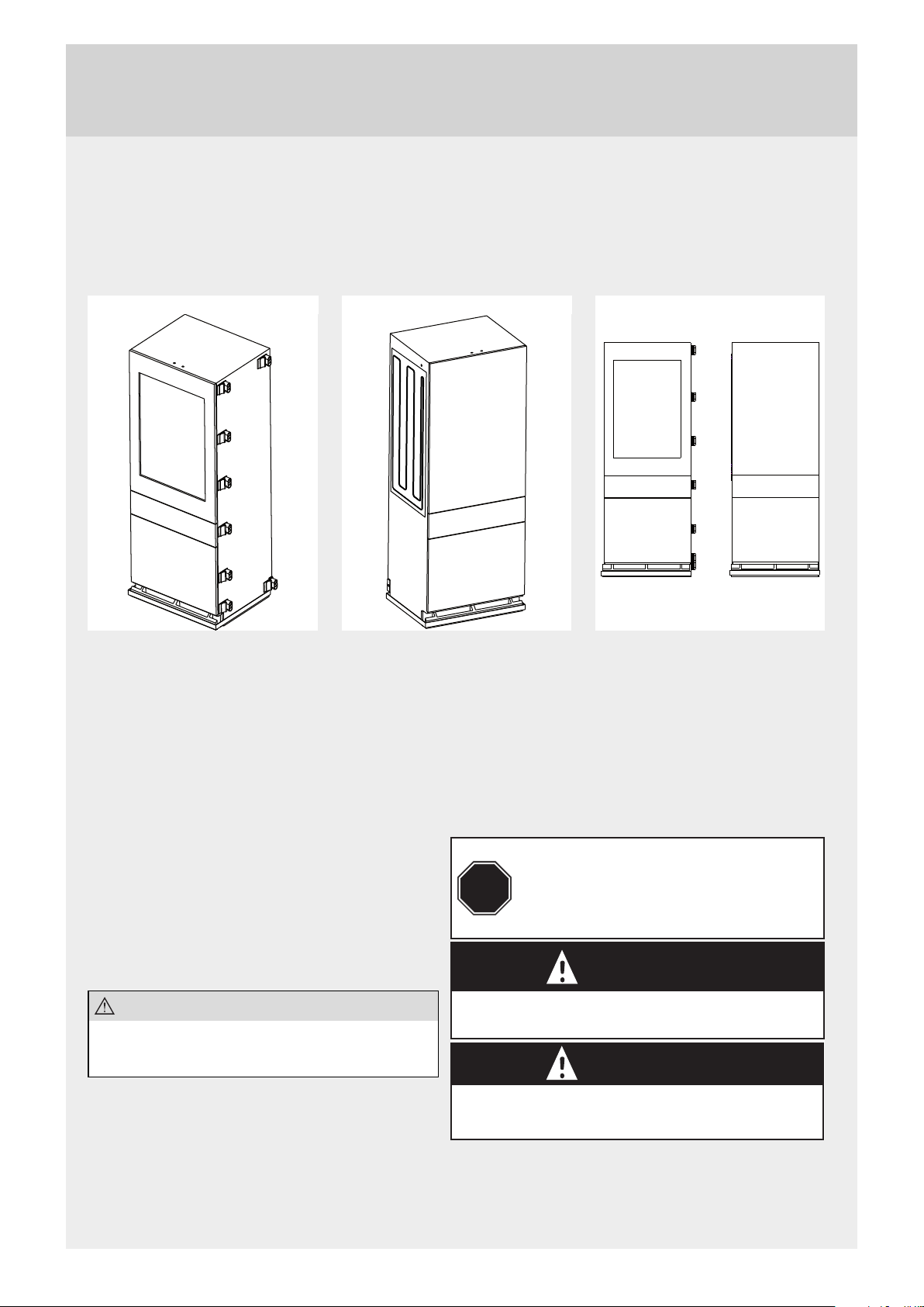
TO BE USED WITH HOUSEHOLD
REFRIGERATORS
BUILT-IN
BOTTOM - FREEZER, 2 DRAWER
Unit 1 - Spacer Clips Installed Unit 2 - Heater Installed
ALL REFERENCES TO ASSEMBLY ARE FROM THE FRONT OF THE UNITS
PARTS PROVIDED:
Installation Instructions (1)
Heater (1)
Transformer (1)
Plastic Cover (1)
Brackets (2)
Tools Required:
#2 Phillips Head Screw Driver
Step Ladder
Open Wrench Set
5 mm. Allen Wrench
Spacer Clips (8)
Strain Relief (1)
Screw, 4,8 x 13 (4)
Bolt, M4 x 45 (1)
Nut, M4 (1)
PPE Required:
Safety Glasses
Safety Gloves
STOP
Washer, star (2)
Bolt, M6 x 45 (3)
Nut, M6 (3)
Washer, fl at (6)
Wiring ”Y” Splitter (1)
BEFORE YOU BEGIN
Read these instructions
completely and carefully
Unit 1
WARNING
Unit 2
NOTE!
While performing installations described in this
book, safety glasses or goggles should be worn.
Disconnect power to the appliance before beginning installation.
Do not operate the refrigerator until the installation is complete.
WARNING
This refrigerator is top heavy and must be handled with care.
Failure to do so can result in the unit tipping over and result in death or serious injury.
Do not cut lower banding on units.
Do not remove foam base pad from front of units.
IMPORTANT SAFETY NOTICE:
This kit is to be installed by a qualifi ed service technician only. Any attempt to repair a major appliance may result in
personal injury and property damage. Neither the manufacturer nor the seller can be responsible for the interpretation of
this information or assume any liability in connection with its use.
3
Page 4
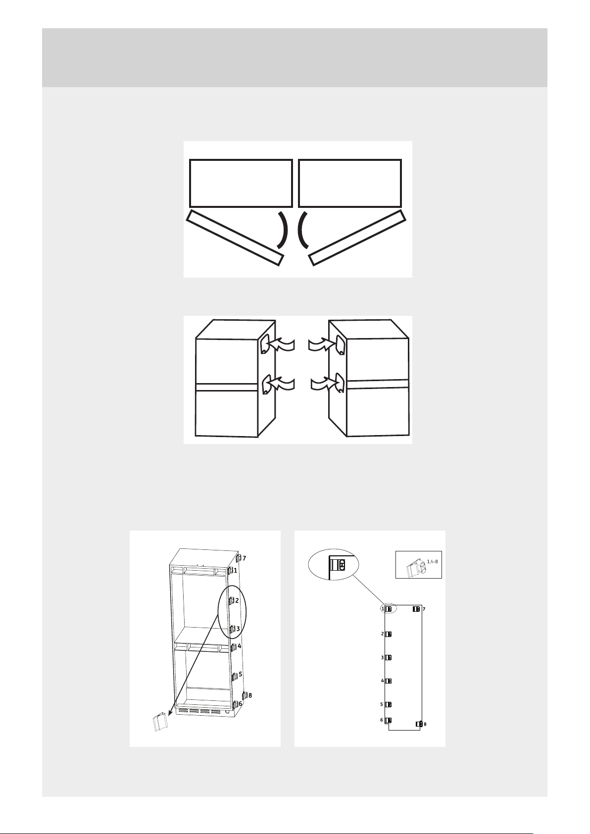
1. The heater kit will only fi t two units, if the doors face each other when opened. Door swing of unit 1 must be
switched from right hand swing to left hand swing.
Required Door Swing (view from above)
Unit 1 Unit 2
2. On sides of refrigerators, remove white stickers from top and center location, to reveal holes in the case. Remove any
labels from sides of refrigeratos and clean the surfaces.
Unit 1
3. Attach spacer clips to the inner side wall of Unit 1. Line up holes in Spacer Clips 1 and 4 with holes in case. Attach
clips 2 and 3 evenly spaced between 1 and 4. Note that clips 2 and 3 are diff erent that the six other clips. It is very
important that you use clips 2 and 3 in those locations only. Clip 6 attaches on the bottom front corner, along the front
edge of Unit 1, same as clips 1 and 4. Clip 5 should be spaced evenly between clip 4 and 6. Clip 7 attaches to the top,
rear corner of Unit 1. Orientation in not critical, Clip 8 is attached in a later step.
Unit 1 Unit 2
Unit 2
Spacer Clips
Unit 2
Spacer Clips 2,3
4
Page 5

4. On Unit 2, use top and center holes to locate the fail heater. There is a hole in the foil heater. The lines up with the hole
at the center of the case. The ”V” notch at the top of the heater, lines up with the top hole in the side of the case.
Remove paper backing from heater and carfully apply heater using these two holes as guides.
Unit 2
Rear
5. In front of cabinet enclosure, move units next to each other, with holes lined up. Make sure heate wire is dressed
towards front of units for use in a late step. Tape heater lead wires to side of Units 2 so that leads are sticking out the
front, below clip 6, and easily reached for use in a later step. Using bolts, washers and nuts, join the two units together
at the front - top and center. Tighten bolts until spacer slips touch Unit 2.
Front
Unit 2
Unit 1
Heater lead wires
5
Page 6

6. Attach joining brackets to rear of each unit, using screws provided with kit, add spacer between brackets. Join with
bolt, washers and nut. Do not cut lower banding strap during this step.
7. Connect water lines to units, plug units into electrical outlets, push units into cabinet enclosure and fasten to anti-tip
brackets.
8. After fastening the anti-tip brackets to ach unit, cut lower banding straps on Units 2 and 2 and remove foam base pad
from front of units.
9. Next, the heater will be joined to the wiring of Unit 2. The heater is a low voltage, DC type heater, so this step consists
of adding a transformer between line voltage and the heater, and the steps needed to mount and wire the transformer.
Remove toekick and air vent cover from front of Unit 2 by emoving four Phillips head screws.
Metal Plate
Vent Cover
To ek i ck
6
Page 7

Fasten heater leads to open slot in vent cover, using the strain relief provided with the kit.
Vent cover
Strain relief
Heater leads
Locate the vertical, metal plate behind the vent cover. There are two holes in the plate for mounting the transformer.
Locate the transformer on the plate and attach using bolts, nuts and washers supplied.
Transformer
Metal plate
7
Page 8

In front of unit, unplug the power cord and replace with the ”Y” splitter supplied in the kit. On the ends of the splitter, plug
in the transformer (black and white leads) and the power cord plug.
To transformer
Y splitter
Unplug main power cord
Attach heater lead wires to transformer lead wires (blue and green leads connect to the heater).
Main power cord
From Transformer
Strain relief
Heater leads
10. Reattach front toekick and air vent cover.
11. Attach front trim piece, provided in kit, along lenght of units from top to botton, by snapping into the clips that werw
attached in step 3.
Vent Cover
Trim cover snaps into the front six spacer clips
8
Page 9

9
Page 10

10
Page 11

Page 12

en (08-15)
 Loading...