

Page 1

Installation
Instructions
Wall-hung
combination boiler
Type C Boilers
G.C.N:
LEAVE THESE INSTRUCTIONS
WITH THE END-USER
Country of destination: GB
MT2002CAL007701001
Page 2

2
TABLE OF CONTENTS
1. GENERAL INFORMATION
1.1 General Instructions
1.2 Overall View
2. INSTALLATION
2.1 Reference Standards
2.2 Siting the Appliance
2.3 Overall Dimensions
2.4 Clearances
2.5 Mounting the Appliance
2.6 Electrical Connection
2.7 Gas Connection
2.8 Water Connections
2.9 Flue Connection
2.10 Room Thermostat Connection
2.11 Electrical/System Diagrams
2.12 Water Circuit Diagrams
3. COMMISSIONING
3.1 Initial Preparation
3.2 Control Panel
3.3 Removing the Front Panel
3.4 Initial Start up
3.5 Operational Adjustments
3.6 Combustion Analysis
3.7 Boiler Safety Systems
3.8 Draining the System
4. GAS ADJUSTMENTS
Gas Adjustment Table
4.1 Changing the Type of Gas
5. MAINTENANCE
6. MISCELLANEOUS
6.1 Wiring Diagram for Two Heating Zones
6.2 Wiring Diagram for Connection to an Ariston Unvented Cylinder
7. Technical Information
Page 3

3
This manual is an integral and essential part of the product. It should be kept
with the appliance so that it can be consulted by the user and our authorised
personnel.
Please carefully read the instructions and notices about the unit contained in
this manual, as they provide important information regarding the safe
installation, use and maintenance of the product.
For operating instructions please consult the separate User Manual.
Read the instructions and recommendations in these Installation Instructions
carefully to ensure proper installation, use and maintenance of the appliance.
Keep this manual in a safe place.You may need it for your own reference while
our Service Centre Technicians or your installer may need to consult it in the
future.
This is a combined appliance for the production of central heating (C.H.) and
domestic hot water (D.H.W.).
This appliance must be used only for the purpose for which it is designed.
The manufacturer declines all liability for damage caused by improper or
negligent use.
No asbestos or other hazardous materials have been used in the fabrication of
this product.
Before connecting the appliance, check that the information shown on the data
plate and the Technical Information table on the back page comply with the
electric, water and gas mains of the property. You will find the data plate on the
reverse of the control panel.
The gas with which this appliance operates is also shown on the label at the
bottom of the boiler.
Do not install this appliance in a damp environment or close to equipment
which spray water or other liquids.
Do not place objects on the appliance.
Do not allow children or inexperienced persons to use the appliance without
supervision.
If you smell gas in the room, do not turn on or off light switches, use the
telephone or any other object which might cause sparks.
Open doors and windows immediately to ventilate the room.
Shut the gas mains tap (on the gas meter) or the valve of the gas cylinder and
call your Gas Supplier immediately.
If you are going away for a long period of time, remember to shut the mains gas
tap or the gas cylinder valve.
Always disconnect the appliance either by unplugging it from the mains or
turning off the mains switch before cleaning the appliance or carrying out
maintenance.
In the case of faults or failure, switch off the appliance and turn off the gas
tap.Do not tamper with the appliance.
For repairs, call your local Authorised Servicing Centre and request the use of
original spare parts. For in-guarantee repairs contact MTS (GB) Limited.
Check the following at least once a year:
1 - Check the seals for the water connections;replace any faulty seals.
2 - Check the gas seals; replace any faulty gas seals.
3 - Visual check of the entire unit.
4 - Visual check of the combustion process or analysis of combustion by-
products (see section 3.6) and cleaning of the burner if needed.
5 - If called for by point. 3, dismantling and cleaning of the combustion
chamber.
6 - If called for by point.4, dismantling and cleaning of the burner jets.
1. GENERAL
INFORMATION
1.1 GENERAL INSTRUCTIONS
Page 4
4
7 - Visual check of the primary heat exchanger:
- check for overheating in the blade assembly;
- clean the exhaust fan if needed.
8 - Adjustment of the gas pressures: ignition pressure, partial load and full load.
9 - Check the heating safety systems:
- safety device for maximum temperature;
- safety device for maximum pressure.
10- Check the gas safety systems:
- safety device for lack of gas or flame ionisation (detection electrode);
- safety device for gas cock.
11- Check the electrical connection (make sure it complies with the instructions in
this manual).
12- Check domestic hot water production efficiency (flow rate and temperature)
13- General check of the combustion by-products of the discharge/ventilation
system.
14- Check the general performance of the unit.
1
2
3
7
11
10
13
21
20
22
23
25
24
18 1914 15
8
6
4
9
12
5
17
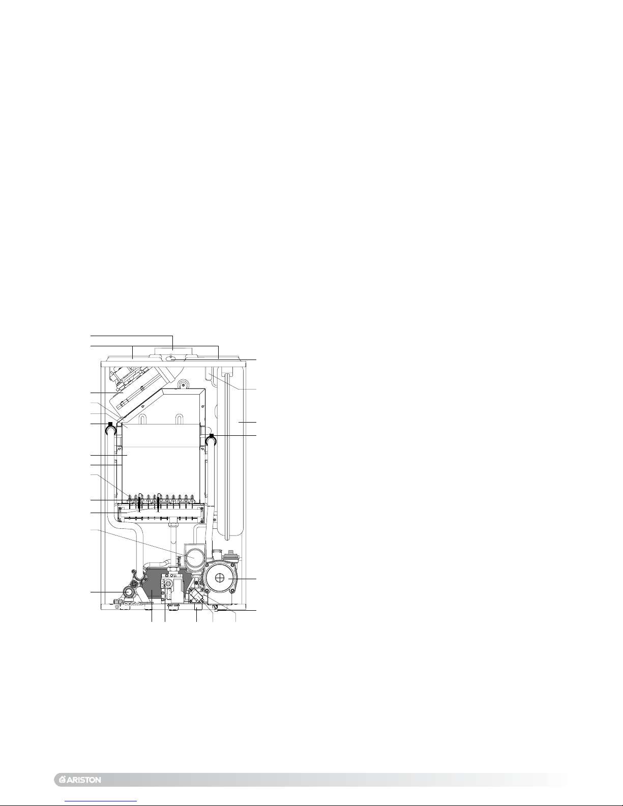
LEGEND:
1. Flue connector
2. Air intake for twin pipe flue systems
3. Fan
4. Combustion chamber hood
5. Main heat exchanger
6. Main circuit temperature probe (flow sensor)
7. Combustion chamber
8. Combustion chamber insulation panel
9. Burner
10. Detection electrode
11. Ignition electrodes
12. Motorised diverter valve
13. Safety valve (3 bar)
14. Secondary heat exchanger
15. Gas valve
17. Domestic cold water inlet filter
18. Spark generator
19. Domestic hot water flow switch
20. Boiler drain valve
21. Circulation pump with automatic air release valve
22. Main circuit temperature probe (return sensor)
23. Expansion vessel
24. Air pressure switch
25. Combustion analysis intakes
1.2 OVERALL VIEW
FIG. 1.0
IN013A
Page 5

5
The technical information and instructions provided herein below are
intended for the installer so that the unit may be installed correctly and
safely.
The installation and initial start up of the boiler must be by a CORGI
Approved Installer in compliance with the installation standards currently in
effect, as well as with any and all local health and safety standards i.e..
CORGI .
This appliance must be installed by a competent installer in
accordance with current Gas Safety (installation & use)
Regulations.
The installation of this appliance must be in accordance with the relevant
requirements of the current Gas Safety (installation & use) Regulations, the
Local Building Regulations, the current I.E.E. Wiring Regulations, the
byelaws of the local water authority, and in Scotland, in accordance with the
Building Standards (Scotland) Regulation and Health and Safety document
No.635 “Electricity at work regs.1989”.
Installation should also comply with the following British Standard Codes of
Practice:
The appliance may be installed in any room or indoor area, although
particular attention is drawn to the requirements of the current I.E.E. Wir ing
Regulations, and in Scotland, the electrical provisions of the Building
Regulations applicable in Scotland, with respect to the installation of the
combined appliance in a room containing a bath or shower.
Where a room-sealed appliance is installed in a room containing a bath
or shower the boiler and any electrical switch or appliance control,
utilising mains electricity should be situated so that it cannot be
touched by a person using the bath or shower.
The location must permit adequate space for servicing and air circulation
around the appliance as indicated in paragraph 2.4.
The location must permit the provision of an adequate flue and termination.
For unusual locations special procedures may be necessary.
BS 6798-1987 gives detailed guidance on this aspect.
A compartment used to enclose the appliance must be designed specifically
for this purpose. No specific ventilation requirements are needed for the
installation within a cupboard.
This appliance is not suitable for outdoor installation.
The type C appliances (in which the combustion circuit, air vent intake
and combustion chamber are air-tight with respect to the room in
which the appliance is installed) can be installed in any type of room.
There are no limitations with respect to ventilation and the volume of the
room itself.The boiler must be installed on a solid, permanent wall to prevent
access to the electrical parts (when live) through the aperture on the back
frame.
2.1 REFERENCE STANDARDS
2. INSTALLATION
Low pressure
pipes BS 6891 1988
Boilers of rated input
not exceeding 60 kW BS 6798 1987
Forced circulation hot
water system BS 5449 1990
Installation of gas hot water
supplies for domestic purposes
( 2ndfamily gases) BS 5546 1990
Flues BS 5440-1 1990
Air supply BS 5440-2 1989
2.2 SITING THE APPLIANCE
Page 6
6
For safety purposes, have a competent person carefully
check the electrical system in the property, as the
manufacturer will not be held liable for damage caused by
the failure to earth the appliance properly or by anomalies
in the supply of power. Make sure that the residential
electrical system is adequate for the maximum power
absorbed by the unit, which is indicated on the rating plate.
In addition, check that the section of cabling is appropriate
for the power absorbed by the boiler.
The boiler operates with alternating current, as indicated in
the technical information table in section 6, where the
maximum absorbed power is also indicated. Make sure
that the connections for the neutral and live wires
correspond to those indicated in the diagram. The
appliance electrical connections are situated on the
reverse of the control panel (see the servicing manual for
further information)
IMPORTANT!
In the event that the power supply cable must be changed,
replace it with one with the same specifications. Make the
connections to the terminal board located within the
control panel, as follows:
- The yellow-green wire should be connected to the
terminal marked with the “”symbol; make sure to re-
use the ferrule mounted on the other supply cord;- The
blue wire should be connected to the terminal marked “N”;
- The brown wire should be connected to the terminal
85 mm
220 mm
Fasten the boiler in place using the template and anchors
supplied with the unit. It is highly recommended that a
spirit level be used to position the boiler so that it is
perfectly level.
For additional information, please consult the instructions
contained in the connection kit and the flue kit.
2.6 ELECTRICAL CONNECTION
2.5 MOUNTING THE APPLIANCE
68 65
400 135
116
120
700
15
25.2
40.2
35
67 67 65 68
acqua
gas
250
200 200
123,5 123,5
250
20
450
300
20
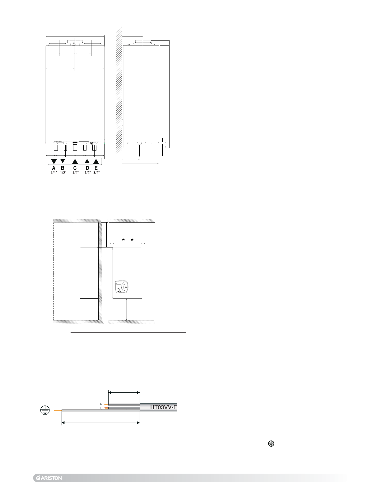
LEGEND:
A = Central Heating Flow (3/4”)
B = Domestic Hot Water Outlet (1/2”)
C = Gas Inlet (3/4”)
D = Domestic Cold Water Inlet (1/2”)
E = Central Heating Return (3/4”)
2.3 OVERALL DIMENSIONS
In order to allow for access to the interior of the boiler for
maintenance purposes, the boiler must be installed in
compliance with the minimum clearances indicated in FIG.2.1
2.4 CLEARANCES
FIG. 2.0
F
IG. 2.1
F
IG. 2.2
*A minimum distance of 20mm is required to each side
of the boiler to allow removal of the outer casing.
Page 7

7
VIEW OF THE BOILER CONNECTIONS
LEGEND:
A= Central Heating Flow
B= Domestic Hot Water Outlet
C= Gas Inlet
D= Domestic Cold Water Inlet
E= Central Heating Return
F= Safety Valve
G = Boiler drain valve
CENTRAL HEATING
Detailed recommendations are given in BS 6798:1987 and BS 5449-1:1990,
the following notes are given for general guidance.
PIPE WORK:
Copper tubing to BS EN 1057:1996 is recommended for water pipes.
2.8 WATER CONNECTIONS
E
A
B
D
C
2.7 GAS CONNECTION
The local gas region contractor connects the gas meter to the service pipe.
If the gas supply for the boiler serves other appliances ensure that an
adequate supply is available both to the boiler and the other appliances
when they are in use at the same time.
Pipe work must be of an adequate size. Pipes of a smaller size than the
boiler inlet connection should not be used.
marked “L”.
Note:The diagrams for the electrical system are indicated in section 2.11.
Warning,this appliance must be earthed.
External wiring to the appliance must be carried out by a qualified technician
and be in accordance with the current I.E.E. Regulations and applicable
local regulations.The UNO range of boilers are supplied for connection to a
230 V
~
50 Hz supply.
The supply must be fused at 3 A.
The method of connection to the electricity supply must facilitate complete
electrical isolation of the appliance, by the use of a fused double pole
isolator having a contact separation of at least 3 mm in all poles or
alternatively, by means of a 3 A fused three pin plug and unswitched
shuttered socket outlet both complying with BS 1363.
The point of connection to the Electricity supply must be readily accessible
and adjacent to the appliance unless the appliance is installed in a bathroom
when this must be sited outside the bathroom.
FIG. 2.4
F
G
E
A
B
C
D
FIG. 2.3
Page 8

8
8
Jointing should be either with capillary soldered or compression fittings.
Where possible pipes should have a gradient to ensure air is carried
naturally to air release points and water flows naturally to drain taps.
The appliance has a built-in automatic air release valve, however it should
be ensured as far as possible that the appliance heat exchanger is not a
natural collecting point for air.
Except where providing useful heat, pipes should be insulated to prevent
heat loss and avoid freezing.
Particular attention should be paid to pipes passing through ventilated
spaces in roofs and under floors.
B
Y-PASS:
The appliance includes an automatic by-pass valve, which protects the main
heat exchanger in case of reduced or interrupted water circulation through
the heating system, due to the closing of thermostatic valves or wheel head
valves within the system.
S
YSTEM DESIGN:
This boiler is suitable only for sealed systems.
Drain Cocks:
These must be located in accessible positions to permit the draining of the
whole system. The taps must be at least 15mm nominal size and
manufactured in accordance with BS 2870:1980.
S
AFETY VALVE DISCHARGE:
The discharge should terminate facing downward on the exterior of the
building in a position where discharging (possibly boiling water & steam) will
not create danger or nuisance, but in an easily visible position, and not
cause damage to electrical components and wiring.
The discharge must not be over an entrance or a window or any other type
of public access.
A
IR RELEASE POINTS:
These must be fitted at all high points where air naturally collects and must
be sited to facilitate complete filling of the system.
The appliance has an integral sealed expansion vessel to accommodate the
increase of water value when the system is heated.
It can accept up to 7 l (1.5 gal) of expansion water. If the heating circuit has
an unusually high water content, calculate the total expansion and add an
additional sealed expansion vessel with adequate capacity.
M
AINS WATER FEED - CENTRAL HEATING:
There must be no direct connection to the mains water supply even through
a non-return valve, without the approval of the Local Water Authority.
F
ILLING:
A temporary method for initially filling the system and replacing lost water
during servicing in accordance with Water Supply Byelaw 14 must be
provided.
D
OMESTIC WATER
The domestic water must be in accordance with the relevant
recommendation of BS 5546:1990. Copper tubing to BS EN 1057:1996 is
recommended for water carrying pipe work and must be used for pipe work
carrying drinking water.
RESIDUAL HEAD OF THE BOILER
600
500
400
300
200
100
0
0 100 200 300 400 500 600 700 800 900 1000 1100 1200
l/h
mbar
Page 9

9
Ø 60/100 mm
F
IG. 2.6
A
BC
D
E
F
G
J
K
HI
L
G
F
The boiler is designed to be connected to a coaxial flue discharge system.
2.9 FLUE CONNECTIONS
FLUE SYSTEM
The provision for satisfactory flue ter mination must be made as described
in BS 5440-1.
The appliance must be installed so that the flue terminal is exposed to outdoor air.
The terminal must not discharge into another room or space such as an
outhouse or lean-to.
It is important that the position of the terminal allows a free passage of air
across it at all times.
The terminal should be located with due regard for the damage or
discolouration that might occur on buildings in the vicinity.
In cold or humid weather water vapour may condense on leaving the flue
terminal.
The effect of such “steaming”must be considered.
If the terminal is less than 2 metres above a balcony, above ground or above
a flat roof to which people have access, then a suitable terminal guard must
be fitted. When ordering a ter minal guard, quote the appliance model
number.
A suitable terminal guard is available from:
TOWER FLUE COMPONENTS
Morley Road
Tonbridge
Kent TN9 1RA
The minimum acceptable spacing from the terminal to obstructions and
ventilation openings are specified in F
IG.2.5.
T
ERMINALPOSTION
mm
A - Directly below an open window or other opening 300
B - Below gutters, solid pipes or drain pipes 75
C - Below eaves 200
D - Below balconies or car-port roof 200
E - From vertical drain pipes and soil pipes 75
F - From internal or external corners 300
G - Above ground or below balcony level 300
H - From a surface facing a terminal 600
I - From a terminal facing a terminal 1200
J - From an opening in the car port
(e.g.door, window) into dwelling 1200
K - Vertically from a terminal in the same wall 1500
L - Horizontally from a terminal in the same wall 300
FIG. 2.5
135.9
Page 10

10
123,5 135
230 MIN *
200
132
Ø 80 mm
The components marked * in FIG 2.8 are present or absent
depending on the type of flue system used by the installer.
In addition, it is also possible to use a split (twin pipe)
system by fitting a special adaptor to the flue connector
and using the aperture for the air vent intake located on
the top part of the combustion chamber.
To utilise the air intake it is necessary to:
1.Remove the air intake cover;
2. Inser t the adaptor into the opening (it is not necessary
to use a gasket or sillicone seal;
3.Inser t the elbow into the air inlet and secure with the
screws supplied (Fig.2.7)
FIG. 2.7
F
IG. 2.8
When fitting the twin pipe
system with a minimum
distance of 60mm to the
wall, it is necessar y to
create a hole 100mm in
diameter to allow the pipe
to be connected to the
elbow (F
IG.2.10).
123,5
200
107
25
ø 100
60 mm
* When running the twin flue pipes to the side from the
boiler, it is neccessary to reduce the height of the air
intake elbow by cutting 25mm from the bottom (F
IG.2.9).
FIG. 2.9
F
IG. 2.10
Page 11

11
IMPORTANT!
For all flue systems, a restrictor
may need to be inserted into the
boilers flue connector; the
restrictor must be ø 42 in
diameter depending on the length
of piping indicated in Table 2.1.
The diagrams illustrate some of the
various designs for coaxial or twin
pipe flue systems (F
IG.2.11 &
FIG.2.12).
For further information on
discharge/ventilation accessories,
see the F
LUE PIPE ACCESSORIES
MANUAL.
Exhaust
Type
C12 (xy)
C32 (xy)
C42 (xy)
C52 (xy)
C82 (xy)
Restrictor
ø 42 mm
L max = 11 m
L max = 18 m
Maximum
Extension
Exhaust/Air
42 m
42 m
42 m
43 m
NO
Restrictor
L min = 11 m
L max = 42 m
L min = 18 m
L max = 43 m
Risk of Condensation Forming
Twin Pipe
Systems
ø 80/80
Piping not insulated
ø 42
restrictor NO
5 m 5 m
5 m 5 m
Piping insulated
ø 42 restrictor NO
5 m 5 m
16 m 16 m
L = Sum of the total length of exhaust + air intake piping.
COAXIAL SYSTEMS
FIG. 2.11
Exhaust
Type
C12 (xx)
C32 (xx)
C42 (xx)
Restrictor
ø 42 mm
L min = 0.5 m
L max = 1 m
Maximum
Extension
Exhaust/Air
L = 3 m
NO
Restrictor
L min = 1 m
L max = 3 m
Risk of Condensation Forming
Coaxial
Systems
ø 60/100
Piping not insulated
ø 42
restrictor NO
NONE NONE
Piping insulated
ø 42 restrictor NO
NONE NONE
TABLE 1.0
Page 12

12
To connect a room thermostat, it is necessary to:
1. - Remove the front panel as indicated in section 3.3.
2.- Rotate the control panel (see fig. 1).
3. - Rotate the two plastic screws (see fig.2).
4. - Pull foward the P.C.B. (see fig. 3).
3. - Insert the thermostat cable through the cable grommet and fasten it by means of the
cable-clamp provided.
4. - Then connect the thermostat wires to the terminal block.
5.- If a remote time clock is to be fitted, disconnect the integral time clock from the P.C.B.
6. - Using a volt-free switching time clock, connect the switching wires from the time clock
following points 1-4 above.
7. - If using an external time clock and room thermostat, these must be connected in
series as points 1-6 above.
Note: Only a two-wire type room thermostat can be used.
An anti-frost device is built-in to the appliances electronic regulation
system.
2.10 ROOM THERMOSTAT
CONNECTION
TWIN PIPE
SYSTEMS
FIG. 2.12
In calculating the lengths of the pipes, the
maximum length “L” must also take into
consideration the values for the
exhaust/air intake end terminals, as well
as 90° elbows for coaxial systems.
The C52 types must comply with the
following requirements:
1 - The exhaust/ air intake pipes must
have the same diameter of
ø 80 mm.
2 - If elbows are to be inserted into the
air intake and/or exhaust system, the
calculation of the overall length must
take into consideration the values for
each elbow, see the F
LUE PIPE
ACCESSORIES MANUAL.
3 - The exhaust pipe must protrude by at
least 0.5 m above the top of the roof
in the event that it is located on the
opposite side of the building to the air
intake (this condition is not obligatory
when the air intake and exhaust are
located on the same side of the
building).
4 - It is not possible to install the C52 type
flues on opposite sides of the building
1
2
3
Page 13

13
LN
FUSE
FUSE
LC 100
CN 202
CN 200
CN 301
1
1
CN 201
CN 204
4
CN 100
CN 205
CN 100
verde
13
3
B
A
CN 104
2
CN 101
1
CN 102
giallo
rosso
H I
J
K
G
A
D
E
F
B
C
R
L
P
O
N
M
Q
1
CN 301
Blk
Blk
Gry
Gry
Gry
Gry
Gry
Gry
Gry
Gry
Blk
Blk
Gry
2
A01
A11
A02 A03 A04 A05
3 456789101112
Az
Rd
Vi
Gry
Wh
1
CN 201
2
A06
A07 A08 A09 A10
3 456789101112
Vi
O
N
P
M
4
CN 100
3
BA
CN 104
2
CN 101
1
CN 102
2.11 ELECTRICAL DIAGRAM
LEGEND:
A = Central Heating Selection (Winter) and
Temperature Adjustment
B = Domestic Hot Water Temperature Adjustment
C = On/Off/Reset Switch
D = Ignition Failure (Lockout) L.E.D.
E = Fume Sensor L.E.D.
F = Ignition L.E.D.(Burner On)
G = Time Clock Connector
H = Circulation Pump Relay
I = Motorised Diverter Valve Relay
J =Fan Relay
K =Gas V alve Relay
L = Remote Control Connection
M =Jumper (Self Test Pressure Adjustment -
see table 3.0)
N =Jumper Ignition Delay (Anti-cycling) Adjustment
O =Jumper Low Temperaure installation (under floor)
P =Jumper (Soft-light Adjustment/Maximum
Heating Adjustment)
Q =Transformer
R = Room Thermostat Connector
A01 =Fan
A02 =Gas Valv e Supply
A03 = Motorised Diverter Valve
A04 = Circulation Pump
A05 = Spark Generator
A06 =Main Circuit Temperature Probe (Flow Sensor)
A07 =Main Circuit Temperature Probe (Return Sensor)
A08 = Air Pressure Switch
A09 = Domestic Hot Water Flow Switch
A10 = Modulator
A11 = Flame Detection Circuit
Colours:
Gry = Grey
Wh = White
Rd = Red
Bl = Azzurro
Vi = Violet
Blk =Black
FIG. 2.14
Page 14

14
1
4
5
8
9
14
15
16
17
18
10
11 12
6
2
7
3
LEGEND:
1. Air Pressure Switch
2. Fan
3. Main Heat Exchanger
4. Main Circuit Temperature Probe (Flow
Sensor)
5. Burner
6. Detection Electrode
7. Ignition Electrode
8. Pressure Gauge
9. Safety V alve
10. Secondary Heat Exchanger
11. Gas Valv e
12. D.H.W.Flow Switch
14. Boiler drain valve
15. Motorised Diverter Valve
16. Automatic By-pass
17. Circulation Pump with Automatic
Air Release Valve
18. Expansion V essel
A. Central Heating Flow
B. Domestic Hot Water Outlet
C. Inlet Gas
D. Domestic Cold Water Inlet
E. Central Heating Return
2.12 WATER CIRCUIT DIAGRAM
FIG. 2.15
SI017A
Page 15

15
MTS (GB) Limited support the initiative.Within the information pack
you will find a copy of the Log Book. It is impor tant that this is
completed in the presence of your customer, they are shown how to use it,
and it is signed by them. Please instruct your customer that they must have
their Log Book with them whenever they contact a service engineer
or us.
Preliminary electrical system checks to ensure electrical safety must be
carried out by a competent person i.e. polarity, earth continuity, resistance to
earth and short circuit.
F
ILLING THE HEATING SYSTEM:
Remove the panels of the case and lower the control panel (see section
3.3 for further information).
Open the central heating flow and return cocks supplied with the
connection kit.
Unscrew the cap on the automatic air release valve one full turn and leave
open permanently.
Close all air release valves on the central heating system.
Gradually open valve(s) at the filling point (filling-loop) connection to the
central heating system until water is heard to flow, do not open fully.
Open each air release tap starting with the lower point and close it only
when clear water, free of air, is visible.
Purge the air from the pump by unscrewing anticlockwise the pump
plug and also manually rotate the pump shaft in the direction
indicated by the pump label to ensure the pump is free.
Close the pump plug.
Continue filling the system until at least 0.7 bar registers on the pressure
gauge.
Inspect the system for water soundness and remedy any leaks
discovered.
F
ILLING OF THE D.H.W. SYSTEM:
Close all hot water draw-off taps.
Open the cold water inlet cock supplied with the connection kit.
Open slowly each draw-off tap and close it only when clear water, free of
bubbles, is visible
G
AS SUPPLY:
Inspect the entire installation including the gas meter, test for soundness
and purge, all as described in BS 6891:1988.
Open the gas cock (supplied with the connection kit) to the appliance and
check the gas connector on the appliance for leaks.
When the installation and filling are completed turn on the central heating
system (section 3.4) and run it until the temperature has reached the boiler
operating temperature. The system must then be immediately flushed
through.
The flushing procedure must be in line with BS 7593:1992 code of practice
for treatment of water in domestic hot water central heating systems.
During this operation, we highly recommend the use of a central heating
flushing detergent (Fernox Superfloc or equivalent), whose function is to
dissolve any foreign matter that may be in the system.
Substances different from these could create serious problems to the
pump or other components.
The use of an inhibitor in the system such as Fernox MB-1 or equivalent is
strongly recommended to prevent corrosion (sludge) damaging the boiler
and system.
Failure to carry out this procedure may invalidate the appliance
warranty.
3. COMMISSIONING
3.1 INITIAL PREP ARATION
Page 16

16
In order to access the inside of the boiler, it is necessary to:
1- Unscrew the two screws “A” on the top of the boiler
2- Remove the screws beneat the boiler
(see below), rotate the case catches
inwards
3- Gently pull the side panels away from the boiler and pull forward to remove the
casing panel.
3.4. INITIAL START-UP
3.3 REMOVING THE
FRONT PANEL
THE CHECKS TO BE RUN BEFORE INITIAL START-UP ARE AS FOLLOWS:
1. Make sure that:
-the screw on the automatic air valve has been loosened when the
system is full;
- If the water pressure in the system is below 0.7 bar, bring it up to the
appropriate level;
- Check to see whether the gas cock is closed;
-Make sure that the electrical connection has been made properly and
that the earth wire is connected to an efficient earthing system;
- Supply power to the boiler by turning the On/Off switch “C” (see F
IG.3.0)
in the position “I” - the L.E.D. “F” will illuminate - turn the selector knob
“A” to the winter /central heating position. This will start the circulation
pump. After 10 seconds, the boiler will signal a shutdown due to ignition
failure. Leave the boiler as it is until all of the air has been bled from the
lines.
- Loosen the cap on the head of the pump to eliminate any air pockets;
- Repeat the procedure for bleeding the radiators of air;
-Open the taps for a brief period;
0
I
4
3
2
5
6
4
3
2
5
6
A
B
C
D
EG F
LEGEND:
A - Central heating selection (winter) and temperature
adjustment knob
B - Ignition failure (lockout) L.E.D. (red)
C - On/Off/ Reset knob
D - Fume sensor L.E.D. (yellow)
E - Domestic hot water temperature adjustment knob
F -On/Off L.E.D. (green)
G - Heating system pressure gauge
3.2 CONTROL PANEL
FIG. 3.0
FR025A
In the event that the red L.E.D. “B” and the yellow L.E.D. “D” light
together, this is due to the water pressure in the system being too
low or a lack of water circulation.
Every time the boiler is turned on the three L.E.D’s “B”, “D” and “F”
will light for approx.1 second.
1 3
2
Page 17

17
(See section 3.2 for references) it is possible to:
- Set the temperature of the heating system by adjusting the knob “A”
- Set the temperature of the domestic hot water by turning knob “E”
To access the areas in which adjustments are made, it is necessary to open
the control panel, as indicated in section 3.3, then rotate the control panel
forward and remove the P.C.B. cover. Access is thereby provided to the
P.C.B. and to the following components:
1. the power supply cable connector;
2. the fuses;
3. Slow Ignition Adjustment and Maximum Heating Adjustment
Jumper “P” used to set the maximum heating adjustment and the slow
ignition adjustment is set to position “B” for normal operation.
To change the factory setting move the jumper “P” from postion “”B” to
postion “A”. The red L.E.D. will begin flash. This indicates that it is now
possible to adjust the slow ignition and the maximum heating adjustment.
The slow ignition adjustment can be carried out by turning knob “E”
(D.H.W. temperature adjustment), the maximum heating adjustment can
be carried out by turning knob “A” (C.H. temperature adjustment)
To store the new settings, return jumper “P” to its original position “B”.
During this operation the boiler must be powered at all times.
4. Setting the Ignition Delay
Jumper “N” controls the ignition delay and is factory set to 2 minutes
(position “B”). By moving the jumper to position “A” the ignition delay is
cancelled (0 minutes).
3.5 OPERATIONAL
ADJUSTMENTS
- Check the system pressure and, if it has dropped, open the filling loop
again to bring the pressure back up to 0.7 bar.
2. Check the exhaust flue for the fumes produced by combustion.
3. Make sure that all gate valves are open;
4. Turn on the gas cock and check the seals on the connections, including
the one for the burner, making sure that the meter does not signal the
passage of gas.Check the connections with a soap solution and
eliminate any leaks.
5. Turn and release the knob “C” to the RESET position for the lighting
system; the spar k will light the main burner. If the burner does not light
the first time, repeat the procedure.
6. Check the minimum and maximum pressure values for the gas going to
the burner; adjust it if needed using the values indicated in the table in
section 4 (See the relative section for burner pressure adjustment within
the servicing manual).
 Loading...