

ARISTON PK 755D GH X LPG IL User Manual
PK 644D GH X LPG IL
PK 755D GH X LPG IL
English
Operating Instructions
HOB
Contents
Operating Instructions,1
Warnings,2
Assistance,3
Description of the appliance,4
Installation,5
Start-up and use,8
Precautions and tips,8
Maintenance and care,9
Troubleshooting,9
שומישו הנקתה תוארוה
םיניינעה ןכות
1 ,שומישו הנקתה תוארוה
14 ,םייריכב שומישו לוחתא
14 ,תוצעו תוריהז יעצמא
18 ,ץראה יבחרב תוריש תונחת
תירבע
םינבומ םייריכ
2 ,תורהזא
3 ,הריכמה רחאל תורש
4 ,םייריכה רואית
13 ,הנקתה
17 ,יוקינו הקוזחת
17 ,תולקת רותיא
Warnings
WARNING: The appliance and its accessible parts
become hot during use. Care should be taken to
avoid touching heating elements. Children less than 8
years of age shall be kept away unless continuously
supervised. This appliance can be used by children
aged from 8 years and above and persons with
reduced physical, sensory or mental capabilities or
lack of experience and knowledge if they have been
given supervision or instruction concerning use of the
appliance in a safe way and understand the hazards
involved. Children shall not play with the appliance.
Cleaning and user maintenance shall not be made
by children without supervision.
WARNING: Unattended cooking on a hob with fat or
oil can be dangerous and may result in re. NEVER
try to extinguish a re with water, but switch off the
appliance and then cover ame e.g. with a lid or a
re blanket.
תורהזא
.שומישה ןמזב םיממחתמ םישיגנה םיקלחהו םייריכה :הרהזא
םידלי .םירעבמב עגממ ענמיהל ידכ תוריהזה יעצמא לכב וטקנ
חוקיפב םה םא אלא םייריכהמ קיחרהל שי םינש 8 ליגל תחתמ
ינבו 8 ליג לעמ םידלי שומישב תויהל םילוכי ולא םייריכ .ףיצר
וא תותחפומ תוישפנ וא תויתשוחת ,תויזיפ תולוכי םע םדא
דציכ וכרדות וא חוקיפב םיאצמנ םה םא ,עדיו ןויסינ ירסח
.תוכורכה תונכסה תא וניבהו חוטב ןפואב םייריכב שמתשהל
תקוזחתו יוקינ .םייריכה םע קחשל םידליל ורשפאת לא
.החגשה אלל םידלי ידי לע עצובת אל שמתשמה
לולע החגשה אלל ןמש וא ןמוש םע םייריכה לע לושיב :הרהזא
םע שא תובכל וסנת לא םלועל .הפירשל םורגלו ןכוסמ תויהל
וא הסכמ םע הבהל תא וסכ ןכמ רחאלו םייריכה תא ובכ .םימ
.שא תכימש
.לושיבה יחטשמ לע םיטירפ ןסחאל ןיא :שא תנכס :הרהזא
תוקנל ידכ ץחלב וא רוטיקב יוקינ ירישכמב ושמתשת לא םלועל
.םייריכה
WARNING: Danger of re: do not store items on the
cooking surfaces.
Never use steam cleaners or pressure cleaners on
the appliance.
Remove any liquid from the lid before opening it. Do
not close the glass cover (if present) when the gas
burners or electric hotplates are still hot.
The appliance is not intended to be operated by
means of an external timer or separate remote
control system.
CAUTION: the use of inappropriate hob guards can
cause accidents.
הסכמ תא ורגסת לא .ותחיתפ ינפל הסכמהמ והשלכ לזונ וריסה
.םימח ןיידע זגה ירעבמ רשאכ )םייק םא( תיכוכזה
תכרעמ וא ינוציח רמייט תועצמאב םייריכה תא וליעפת לא
.תדרפנ קוחרמ הטילש
םורגל לולע ,םימיאתמ אל םייריכל השיג ינגמב שומיש :תוריהז
.תונואתל
2
Assistance
Communicating:
• the type of problem encountered.
• appliance model (Mod.)
• serial number (S/N)
This information is found on the data plate located on the appliance and/or
on the packaging.
הריכמה רחאל תורש
ףוסבש המישרב ונייע( םכירוגמ םוקמ בורקה תורישה זכרמ םע רשק ורצ ,תכשמנ היעבהו
:םיאבה םיטרפב םתוא ונכדעו )תרבוחה
.היעבה גוס •
וא תוירחאה תדועתב םושרש יפכ )Mod.) םכתושרבש םגדה יוהיזל תוביתה ישאר •
.םייריכל תקבדומה םינותנה תיוותב
םניאש ףוליח יקלח לבקל וברסו ,ןרציה ידי לע םיכמסומ םניאש םיאנכטל ונפת לא םלוע •
.םיירוקמ
3
Description of the appliance
1
1
2
4
3
םייריכה רואית
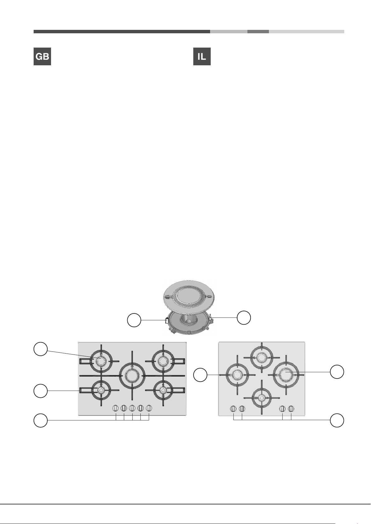
Overall view
1. Support Grid for COOKWARE
2. GAS BURNERS
3. Control Knobs for GAS BURNERS
4. Ignition for GAS BURNERS
5. SAFETY DEVICES
• GAS BURNERS differ in size and power. Use the diameter of the cookware
to choose the most appropriate burner to cook with.
• Control Knobs for GAS BURNERS adjust the power or the size of the
ame.
• GAS BURNER IGNITION enables a specic burner to be lit automatically.
• SAFETY DEVICE stops the gas flow if the flame is accidentally
extinguished.
! The largest slot should be inserted into the ignition.
תיללכ הריקס
.1לושיבה יריסל הכימת תשר
.2זגה ירעבמ
.3זגה ירעבמ תרקב ירותפכ
4 .זגה ירעבמל תצמ
.5תוחיטב ןקתה
רתויב םיאתמה רעבמה תא ורחב .םומיחה תמצועבו לדוגב םינוש םייריכב זגה ירעבמ •
.םישמתשמ םתא ובש ריסה רטוקל
.הבהלה לדוג תא תא םינווכמ זגה ירעבמ תרקב ירותפכ •
.יוצרה רעבמה תא יטמוטוא ןפואב תיצהל םירשפאמ זגה ירעבמ לש םיתצמה •
.תוימואתפב הבכש רעבמל זגה תמירז תא רצוע תוחיטבה ןקתה •
.תצמה ךותל סינכהל שי רעבמה תעבט לש בחרה ץירחה תא !
5
2
3
4
Installation
555 mm
55 mm
475 mm
600mm min.
420mm min.
650mm min.
! Before operating your new appliance please read this instruction booklet
carefully. It contains important information for safe use, installation and care
of the appliance.
! Please keep these operating instructions for future reference. Pass them on
to possible new owners of the appliance.
Positioning
! Keep packaging material out of the reach of children. It can become a choking
or suffocation hazard (see Precautions and tips).
! The appliance must be installed by a qualied professional according to the
instructions provided. Incorrect installation may cause harm to people and
animals or may damage property.
! This unit may be installed and used only in permanently ventilated rooms
in accordance with current national regulations. The following requirements
must be observed:
• The room must be equipped with an air extraction system that expels
any combustion fumes. This may consist of a hood or an electric fan that
automatically starts each time the appliance is switched on.
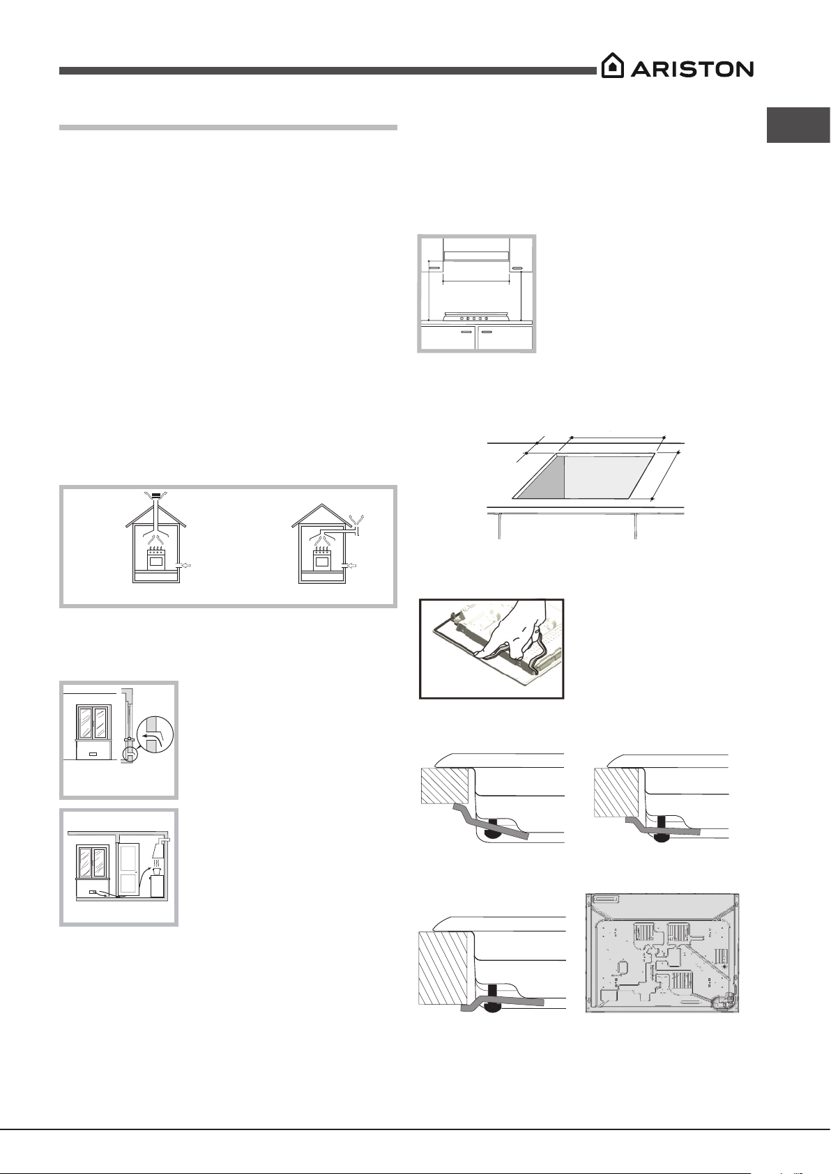
Fitting the appliance
The following precautions must be taken when installing the hob:
• Kitchen cabinets adjacent to the appliance and taller than the top of the
hob must be at least 200 mm from the edge of the hob.
• Hoods must be installed according to their relative installation instruction
manuals and at a minimum distance of 650 mm from the hob )see gure(.
• Place the wall cabinets adjacent to the hood at a minimum height of 420
mm from the hob )see gure(.
If the hob is installed beneath a wall cabinet,
the latter must be situated at a minimum of 700
mm above the hob.
• The installation cavity should have the dimensions indicated in the gure.
Fastening hooks are provided, allowing you to fasten the hob to tops that
are between 20 and 40 mm thick. To ensure the hob is securely fastened
to the top, we recommend you use all the hooks provided.
GB
In a chimney stack or branched flue.
(exclusively for cooking appliances)
Directly to
the Outside
• The room must also allow proper air circulation, as air is needed for
combustion to occur normally. The ow of air must not be less than 2 m3/h
per kW of installed power.
The air circulation system may take air directly
from the outside by means of a pipe with an
inner cross section of at least 100 cm
2
; the
opening must not be vulnerable to any type
Examples of
ventilation holes
for comburant air.
Adjacent
Room
A
Room to be
Vented
of blockages.
The system can also provide the air needed for
combustion indirectly, i.e. from adjacent rooms
tted with air circulation tubes as described
above. However, these rooms must not be
communal rooms, bedrooms or rooms that
may present a re hazard.
Enlarging the ventilation slot
between window and floor.
• Liquid petroleum gas sinks to the oor as it is heavier than air. Therefore,
rooms containing LPG cylinders must also be equipped with vents to allow
gas to escape in the event of a leak. As a result LPG cylinders, whether
partially or completely full, must not be installed or stored in rooms or
storage areas that are below ground level (cellars, etc.). It is advisable to
keep only the cylinder being used in the room, positioned so that it is not
subject to heat produced by external sources )ovens, replaces, stoves,
etc. ) which could raise the temperature of the cylinder above 50°C.
Before the installation remove the grids and burners from the hob and turn it
upside down, making sure you don’t damage the thermocouples and spark
plugs.
Apply the seals that come with the
appliance along the outer edges of
the hob to prevent any passage of air,
humidity and water (see Figure).
For proper application make sure the
surfaces to be sealed are clean, dry and
free of any grease/oil.
Hook fastening diagram
Hooking position for top
H=20mm
Hooking position for top
H=30mm
Front
Hooking position for top
!
Use the hooks contained in the “accessory pack”.
H=40mm
Back
5
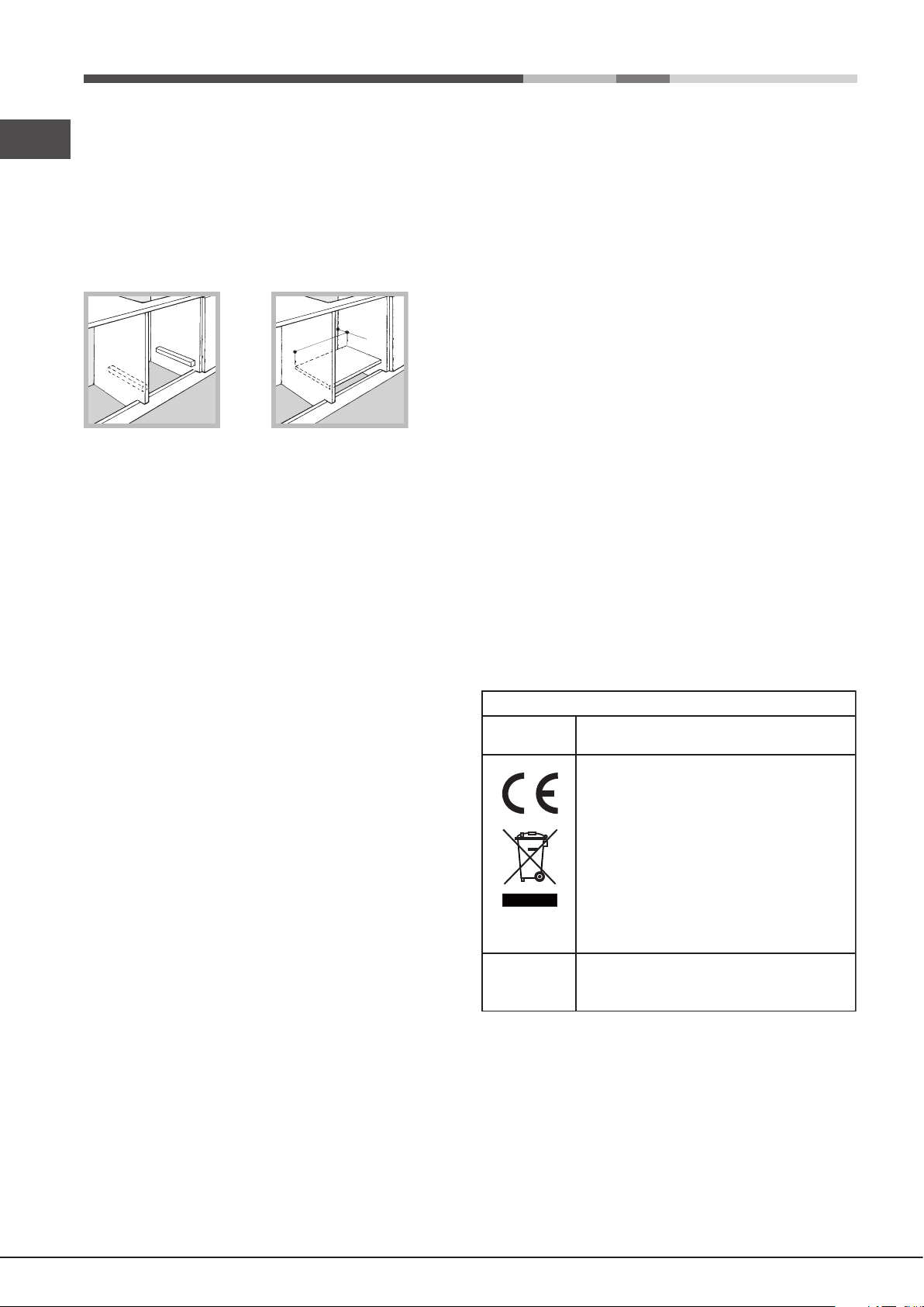
• Where the hob is not installed over a built-in oven, a wooden panel must
GB
be installed as insulation. This must be placed at a minimum distance of
20 mm from the lower part of the hob.
Ventilation
To ensure adequate ventilation, the back panel of the cabinet must be
removed. It is advisable to install the oven so that it rests on two strips of
wood, or on a completely at surface with an opening of at least 45 x 560
mm (see diagrams).
45 mm.
560 mm.
! The hob can only be installed above built-in ovens with a cooling ventilation
system.
Electrical connection
Hobs equipped with a three-pole power supply cable are designed to operate
with alternating current at the voltage and frequency indicated on the data
plate (this is located on the lower part of the appliance). The earth wire in the
cable has a green and yellow cover. If the appliance is to be installed above
a built-in electric oven, the electrical connection of the hob and the oven must
be carried out separately, both for electrical safety purposes and to make
extracting the oven easier.
Connecting the supply cable to the mains
Install a standardised plug corresponding to the load indicated on the data
plate.
The appliance must be directly connected to the mains using an omnipolar
circuit-breaker with a minimum contact opening of 3 mm installed between the
appliance and the mains. The circuit-breaker must be suitable for the charge
indicated and must comply with current electrical regulations (the earthing
wire must not be interrupted by the circuit-breaker). The supply cable must
not come into contact with surfaces with temperatures higher than 50°C.
! The installer must ensure that the correct electrical connection has been
made and that it is compliant with safety regulations.
Before connecting to the power supply, make sure that:
• The appliance is earthed and the plug is compliant with the law.
• The socket can withstand the maximum power of the appliance, which is
indicated on the data plate.
• The voltage is in the range between the values indicated on the data plate.
• The socket is compatible with the plug of the appliance. If the socket is
incompatible with the plug, ask an authorised technician to replace it. Do
not use extension cords or multiple sockets.
Gas connection
The appliance should be connected to the main gas supply in compliance
with current national regulations. Before carrying out the connection, make
sure the cooker is compatible with the gas supply you wish to use.
! Check that the pressure of the gas supply is consistent with the values
indicated in Table 1 )“Burner and nozzle specications”(. This will ensure the
safe operation and longevity of your appliance while maintaining efcient
energy consumption.
Connection with a rigid pipe (copper or steel)
! Connection to the gas system must be carried out in such a way as not to
place any strain of any kind on the appliance.
There is an adjustable L-shaped pipe tting on the appliance supply ramp
and this is tted with a seal in order to prevent leaks. The seal must always
be replaced after rotating the pipe tting )seal provided with appliance(. The
gas supply pipe tting is a threaded 1/2 gas cylindrical male attachment.
Connecting a flexible jointless stainless steel pipe to a threaded
attachment
The gas supply pipe tting is a threaded 1/2 gas cylindrical male attachment.
These pipes must be installed so that they are never longer than 2000 mm
when fully extended. Once connection has been carried out, make sure that
the exible metal pipe does not touch any moving parts and is not compressed.
! Only use pipes and seals that comply with current national regulations.
Checking the tightness of the connection
! When the installation process is complete, check the pipe ttings for leaks
using a soapy solution. Never use a ame.
DATA PLATE
Electrical
connections
ECODESIGN
see data plate
This appliance conforms to the following
European Economic Community directives:
- 2006/95/EC dated 12/12/06 (Low Voltage)
and subsequent amendments
- 2004/108/EC dated 15/12/04
(Electromagnetic Compatibility) and
subsequent amendments
- 93/68/EEC dated 22/07/93 and subsequent
amendments.
- 2009/142/EC dated 30/11/06 (Gas) and
subsequent amendments
- 2012/19/EU and subsequent amendments.
EU Regulation no. 66/2014 implementing
Directive 2009/125/EC.
standard EN 30-2-1
! Once the appliance has been installed, the power supply cable and the
electrical socket must be easily accessible.
! The cable must not be bent or compressed.
! The cable must be checked regularly and replaced by authorised technicians
only (see Assistance).
! The manufacturer declines any liability should these safety measures not
be observed.
6
 Loading...