ARISTON PHN 962 TS/IX/A User Manual

0 (0)

PHN 962 TS/IX/A

یبرع

ليغشتلاتاميلعت

نيخستفر

تايوتحم

1،ليغشتلاتاميلعت

3،تاريذحت

4،ةدعاسملا

5،زاهجلافصو

21،بيكرتلا

22،مادختسلااوليغشتلا

22،حئاصنوريذحتلئاسو

24،ةيانعلاوةنايصلا

24،اهلحولكاشملافاشكتسا

English

Operating Instructions

HOB

Contents

Operating Instructions,1

Warnings,2

Assistance,4

Description of the appliance,5

Installation,6

Start-up and use,10

Precautions and tips,10

Maintenance and care,11

Troubleshooting,11

Français

Mode d’emploi

TABLE DE CUISSON

Sommaire

Mode d’emploi,1

Avertissements,2

Assistance,4

Description de l’appareil,5

Installation,13

Mise en marche et utilisation,17

Précautions et conseils,17

Nettoyage et entretien,18

Anomalies et remèdes,19


Warnings

Avertissements

WARNING: The appliance and its accessible parts become hot during use. Care should be taken to avoid touching heating elements. Children less than 8 years of age shall be kept away unless continuously supervised. This appliance can be used by children aged from 8 years and above and persons with reduced physical, sensory or mental capabilities or lack of experience and knowledge if they have been given supervision or instruction concerning use of the appliance in a safe way and understand the hazards involved. Children shall not play with the appliance. Cleaning and user maintenance shall not be made by children without supervision.

WARNING: Unattended cooking on a hob with fat or oilcanbedangerousandmayresultinfire.NEVER try to extinguish a fire with water, but switch off the appliance and then cover flame e.g. with a lid or a fire blanket.

WARNING:Dangeroffire:donotstoreitemsonthe cooking surfaces.

Never use steam cleaners or pressure cleaners on the appliance.

Remove any liquid from the lid before opening it. Do not close the glass cover (if present) when the gas burners or electric hotplates are still hot.

The appliance is not intended to be operated by means of an external timer or separate remote control system.

CAUTION: the use of inappropriate hob guards can cause accidents.

ATTENTION : Cet appareil ainsi que ses parties accessibles deviennent très chauds pendant leur fonctionnement. Il faut faire attention à ne pas toucher les éléments chauffants. Ne pas faire approcher les enfants de moins de 8 ans à moins qu’ils ne soient sous surveillance constante. Le présent appareil peut être utilisé par des enfants de plus de 8 ans et par des personnes présentant des capacités physiques, sensorielles ou mentales réduites ou n’ayant pas l’expérience ou les connaissances indispensables, à condition qu’ils soient sous bonne surveillance ou qu’ils aient reçu les instructions nécessaires pour une utilisation de l’appareil en toute sécurité et à condition qu’ils se rendent compte des dangers encourus. Les enfants ne doivent pas jouer avec l’appareil. Les opérations de nettoyage et d’entretien ne doivent pas être effectuées par des enfants non surveillés.

ATTENTION : Laisser un récipient de cuisson avec de l’huile ou de la graisse sur un foyer est dangereux et risque d’entraîner un incendie. Il ne faut JAMAIS essayer d’éteindre une flamme ou un incendie avec de l’eau ! Il faut éteindre l’appareil et couvrir la flamme avec un couvercle, par exemple, ou avec une couverture anti-feu.

ATTENTION : Risque d’incendie : ne pas laisser d’objets sur les surfaces de cuisson.

Ne jamais nettoyer l’appareil avec des nettoyeurs vapeur ou haute pression.

Essuyer tout liquide pouvant se trouver sur le couvercle avant de l’ouvrir. Ne pas abaisser le couvercle en verre (s’il y en a un) tant que les brûleurs gaz ou la plaque électrique sont chauds.

Cet appareil ne peut pas être allumé au moyen d’un temporisateur extérieur ou d’un système de commande à distance séparé.

ATTENTION : l’utilisation de protections de table inappropriées peut causer des incendies.

2

تاريذحت

.مادختسلاا ءانثأ ةنخاس ةفوشكملا ءازجلأاو زاهجلا حبصي :ريذحت نأ بجي .نيخستلا رصانعلا ةسملام بنجتل صرحلا مازتلا بجي ةظحلام كانه نكت مل ام نيديعب ماوعأ 8 نم لقلأا لافطلأا لظي 8 رمعنملافطلأاةطسوبزاهجلااذهمادختسانكمي.مهلةرمتسم تاردقلاوأ،ةيدسجلاتاقاعلإايوذةطساوبكلذكو،رثكأفتاونس ةفرعمو ةليلق ةبرجت مهيدل نمم وأ ،ةدودحملا ةيلقعلاو ةيسحلا زاهجلامادختسابقلعتياميفمهبيردتوأمهداشرإمتاذإلاإ،ةدودحم ثبعي لاأ بجي .اهيلع يوطني يتل رطاخملا اومهفو ةنمآ ةقيرطب ةطساوب زاهجلا ةنايصو فيظنت متي لاأ بجي .زاهجلاب لافطلأا

.مهيلع فارشإ نودب لافطلأا

تويزلا وأ نوهدلا مادختساب ماعطلا يهط يدؤي نأ نكمي :ريذحت لا.قيرحبوشنليدؤيدقوًارطخفارشإنودبنيخستلافرىلع زاهجلاءافطإبمقنكلو،ءاملامادختسابنارينلادامخإًاقلطملواحت

.لاثمً ةيناطب وأ ءاطغ مادختساب بهللا ةيطغت مث

حطسأ ىلع ءايشأ نيزختب مقت لا :قيرحلا بوشن رطخ :ريذحت

.يهطلا

.زاهجلا عم طغضلاب تافظنملا وأ راخبلاب تافظنملا ادبأ مدختست لا

امنيب )دجو نإ(ءاطغلاقلغت لا .هحنفلبق ءاطغلا نملئاسلا جرخأ

.ةنخاس تلاز ام وأ ةلعتشم قراحملا نوكت

ماظنوأتقولليجراخدادعةطساوبليغشتللدعمُريغزاهجلااذه

.دعب نع مكحتلل يجراخ

ىلإ نيخستلا ففرلأ ةبسانم ريغ ةيطغأ مادختسا يدؤي دق :ريذحت

.ثداوح عوقو

3

Assistance

Communicating:

the type of problem

appliance model (Mod.)

serial number (S/N)

This information is found on the data plate located on the appliance and/or on the packaging.

Assistance

Indiquez-lui:

le type de défaut

le modèle de votre appareil (Mod.)

son numéro de série (S/N)

Ces informations figurent sur la plaquette signalétique apposée sur votre appareil et/ou sur son emballage.

ةدعاسملا

:لاصتلاا

.هدمآدوجوبلاکشاعون

.)Mod.(هاگتسدلدم

.)S/N(نآلایرسهرامش

.ةوبعلاىلعوأ/وزاهجلاىلعةدوجوملاتانايبلاةحولىلعاهدجتنأنكميتامولعملاهذه

4

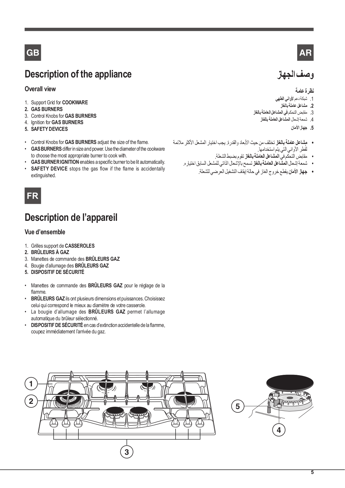
Description of the appliance

Overall view

1.Support Grid for COOKWARE

2.GAS BURNERS

3.Control Knobs for GAS BURNERS

4.Ignition for GAS BURNERS

5.SAFETY DEVICES

Control Knobs for GAS BURNERS adjust the size of the flame.

GASBURNERSdiffer in size and power. Use the diameter of the cookware to choose the most appropriate burner to cook with.

GAS BURNER IGNITION enablesaspecificburnertobelitautomatically.

SAFETY DEVICE stops the gas flow if the flame is accidentally extinguished.

زاهجلافصو

ةماعةرظن

يهطلايناولأمعدةكبش1 .

زاغلابةلماعلعاشم2 . زاغلابةلماعلالعاشملايفمكحتلاضباقم3 .

زاغلابةلماعلالعاشملالاعشإةعمش4 .

ناملأازاهج5 .

ةمئلامرثكلأالعشملارايتخابجي.ةردقلاوداعبلأاثيحنمفلتختزاغلابةلماعلعاشم•

.اهمادختسامتييتلايناولأارطقلُ

.ةلعشلاطبضبموقتزاغلابةلماعلالعاشملايفمكحتلاضباقم•

.هرايتخاقباسلالعشملليتاذلالاعشلإابحمستزاغلابةلماعلالعاشملالاعشإةعمش•

.ةلعشلليضرعلاليغشتلافاقيإةلاحيفزاغلاجورخعطقيناملأازاهج•

Description de l’appareil

Vue d’ensemble

1.Grilles support de CASSEROLES

2.BRÛLEURS À GAZ

3.Manettes de commande des BRÛLEURS GAZ

4.Bougie d’allumage des BRÛLEURS GAZ

5.DISPOSITIF DE SÉCURITÉ

Manettes de commande des BRÛLEURS GAZ pour le réglage de la flamme.

BRÛLEURS GAZ ils ont plusieurs dimensions et puissances. Choisissez celui qui correspond le mieux au diamètre de votre casserole.

La bougie d’allumage des BRÛLEURS GAZ permet l’allumage automatique du brûleur sélectionné.

DISPOSITIFDESÉCURITÉ encasd’extinctionaccidentelledelaflamme, coupez immédiatement l’arrivée du gaz.

1


2

5


4

3

5

ARISTON PHN 962 TS/IX/A User Manual

GB Installation

!Before operating your new appliance please read this instruction booklet carefully. It contains important information for safe use, installation and care of the appliance.

!Please keep these operating instructions for future reference. Pass them on to possible new owners of the appliance.

Positioning

!Keep packaging material out of the reach of children. It can become a choking or suffocation hazard (see Precautions and tips).

!Theappliancemustbeinstalledbyaqualifiedprofessionalaccordingtothe instructions provided. Incorrect installation may cause harm to people and animals or may damage property.

!This unit may be installed and used only in permanently ventilated rooms in accordance with current national regulations). The following requirements must be observed:

• The room must be equipped with an air extraction system that expels any combustion fumes. This may consist of a hood or an electric fan that automatically starts each time the appliance is switched on.


In a chimney stack or branched flue.

Directly to


(exclusively for cooking appliances)

the Outside


The room must also allow proper air circulation, as air is needed for combustiontooccurnormally.Theflowofairmustnotbelessthan2m3/h per kW of installed power.


The air circulation system may take air directly


from the outside by means of a pipe with an


inner cross section of at least 100 cm2; the


opening must not be vulnerable to any type

A

of blockages.


Examples of ventilation holes for comburant air.

Adjacent

Room to be

Room

Vented

Enlarging the ventilation slot

between window and floor.

The system can also provide the air needed for combustion indirectly, i.e. from adjacent rooms fitted with air circulation tubes as described above. However, these rooms must not be communal rooms, bedrooms or rooms that may present a fire hazard.

Intensive and prolonged use of the appliance may necessitate supplemental ventilation, e.g. opening a window or increasing the power of the air intake system (if present).

Liquidpetroleumgassinkstothefloorasitisheavierthanair.Therefore, rooms containing LPG cylinders must also be equipped with vents to allow gas to escape in the event of a leak. As a result LPG cylinders, whether partially or completely full, must not be installed or stored in rooms or storage areas that are below ground level (cellars, etc.). It is advisable to keep only the cylinder being used in the room, positioned so that it is not subject to heat produced by external sources(ovens, fireplaces, stoves, etc. ) which could raise the temperature of the cylinder above 50°C.

Fitting the appliance

The following precautions must be taken when installing the hob:

Kitchen cabinets adjacent to the appliance and taller than the top of the hob must be at least 200 mm from the edge of the hob.

Hoods must be installed according to their relative installation instruction manualsandataminimumdistanceof650mmfromthehob(seefigure).

Place the wall cabinets adjacent to the hood at a minimum height of 420 mm from the hob (see figure).


If the hob is installed beneath a wall cabinet,


the latter must be situated at a minimum of 700


650mm min.


600mm min.


420mm min.


mm above the hob.


Theinstallationcavityshouldhavethedimensionsindicatedinthefigure.

Fastening hooks are provided, allowing you to fasten the hob to tops that are between 20 and 40 mm thick. To ensure the hob is securely fastened

to the top, we recommend you use all the hooks provided.

min. 55 mm.

475

mm .

835 mm.

Before the installation remove the grids and burners from the hob and turn it upside down, making sure you don’t damage the thermocouples and spark plugs.

Apply the seals that come with the appliance along the outer edges of the hob to prevent any passage of air, humidity and water (see Figure).

For proper application make sure the surfaces to be sealed are clean, dry and free of any grease/oil.

Hook fastening diagram

Hooking position for top H=20mm Hooking position for top H=30mm

Front

Hooking position for top H=40mm Back

! Use the hooks contained in the “accessory pack”.

Where the hob is not installed over a built-in oven, a wooden panel must be installed as insulation. This must be placed at a minimum distance of 20 mm from the lower part of the hob.

6

Ventilation

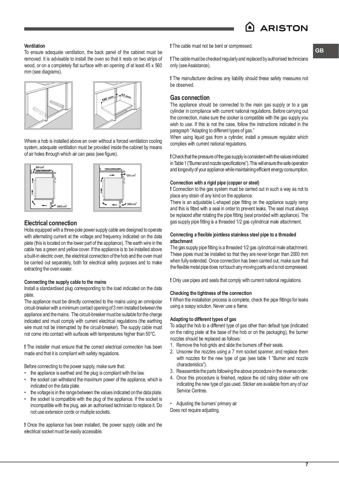
To ensure adequate ventilation, the back panel of the cabinet must be removed. It is advisable to install the oven so that it rests on two strips of wood, or on a completely flat surface with an opening of at least 45 x 560 mm (see diagrams).

.

45

mm.

mm


560


Where a hob is installed above an oven without a forced ventilation cooling system, adequate ventilation must be provided inside the cabinet by means of air holes through which air can pass (see figure).

Electrical connection

Hobs equipped with a three-pole power supply cable are designed to operate with alternating current at the voltage and frequency indicated on the data plate (this is located on the lower part of the appliance). The earth wire in the cable has a green and yellow cover. If the appliance is to be installed above a built-in electric oven, the electrical connection of the hob and the oven must be carried out separately, both for electrical safety purposes and to make extracting the oven easier.

Connecting the supply cable to the mains

Install a standardised plug corresponding to the load indicated on the data plate.

The appliance must be directly connected to the mains using an omnipolar circuit-breaker with a minimum contact opening of 3 mm installed between the appliance and the mains. The circuit-breaker must be suitable for the charge indicated and must comply with current electrical regulations (the earthing wire must not be interrupted by the circuit-breaker). The supply cable must not come into contact with surfaces with temperatures higher than 50°C.

! The installer must ensure that the correct electrical connection has been made and that it is compliant with safety regulations.

Before connecting to the power supply, make sure that:

the appliance is earthed and the plug is compliant with the law.

the socket can withstand the maximum power of the appliance, which is indicated on the data plate.

the voltage is in the range between the values indicated on the data plate.

the socket is compatible with the plug of the appliance. If the socket is incompatible with the plug, ask an authorised technician to replace it. Do not use extension cords or multiple sockets.

! Once the appliance has been installed, the power supply cable and the electrical socket must be easily accessible.

! The cable must not be bent or compressed.

GB

!The cable must be checked regularly and replaced by authorised technicians only (see Assistance).

!The manufacturer declines any liability should these safety measures not be observed.

Gas connection

The appliance should be connected to the main gas supply or to a gas cylinder in compliance with current national regulations. Before carrying out the connection, make sure the cooker is compatible with the gas supply you wish to use. If this is not the case, follow the instructions indicated in the paragraph “Adapting to different types of gas.”

When using liquid gas from a cylinder, install a pressure regulator which complies with current national regulations.

!Checkthatthepressureofthegassupplyisconsistentwiththevaluesindicated inTable1(“Burnerandnozzlespecifications”).Thiswillensurethesafeoperation andlongevityofyourappliancewhilemaintainingefficientenergyconsumption.

Connection with a rigid pipe (copper or steel)

! Connection to the gas system must be carried out in such a way as not to place any strain of any kind on the appliance.

There is an adjustable L-shaped pipe fitting on the appliance supply ramp and this is fitted with a seal in order to prevent leaks. The seal must always be replaced after rotating the pipe fitting(seal provided with appliance).The gas supply pipe fitting is a threaded 1/2 gas cylindrical male attachment.

Connecting a flexible jointless stainless steel pipe to a threaded attachment

Thegassupplypipefittingisathreaded1/2gascylindricalmaleattachment.

These pipes must be installed so that they are never longer than 2000 mm when fully extended. Once connection has been carried out, make sure that theflexiblemetalpipedoesnottouchanymovingpartsandisnotcompressed.

! Only use pipes and seals that comply with current national regulations.

Checking the tightness of the connection

! When the installation process is complete, check the pipe fittings for leaks using a soapy solution. Never use a flame.

Adapting to different types of gas

To adapt the hob to a different type of gas other than default type (indicated on the rating plate at the base of the hob or on the packaging), the burner nozzles should be replaced as follows:

1.Remove the hob grids and slide the burners off their seats.

2.Unscrew the nozzles using a 7 mm socket spanner, and replace them with nozzles for the new type of gas (see table 1 “Burner and nozzle characteristics”).

3.Reassemble the parts following the above procedure in the reverse order.

4.Once this procedure is finished, replace the old rating sticker with one indicating the new type of gas used. Sticker are available from any of our Service Centres.

• Adjusting the burners’ primary air Does not require adjusting.

7

GB

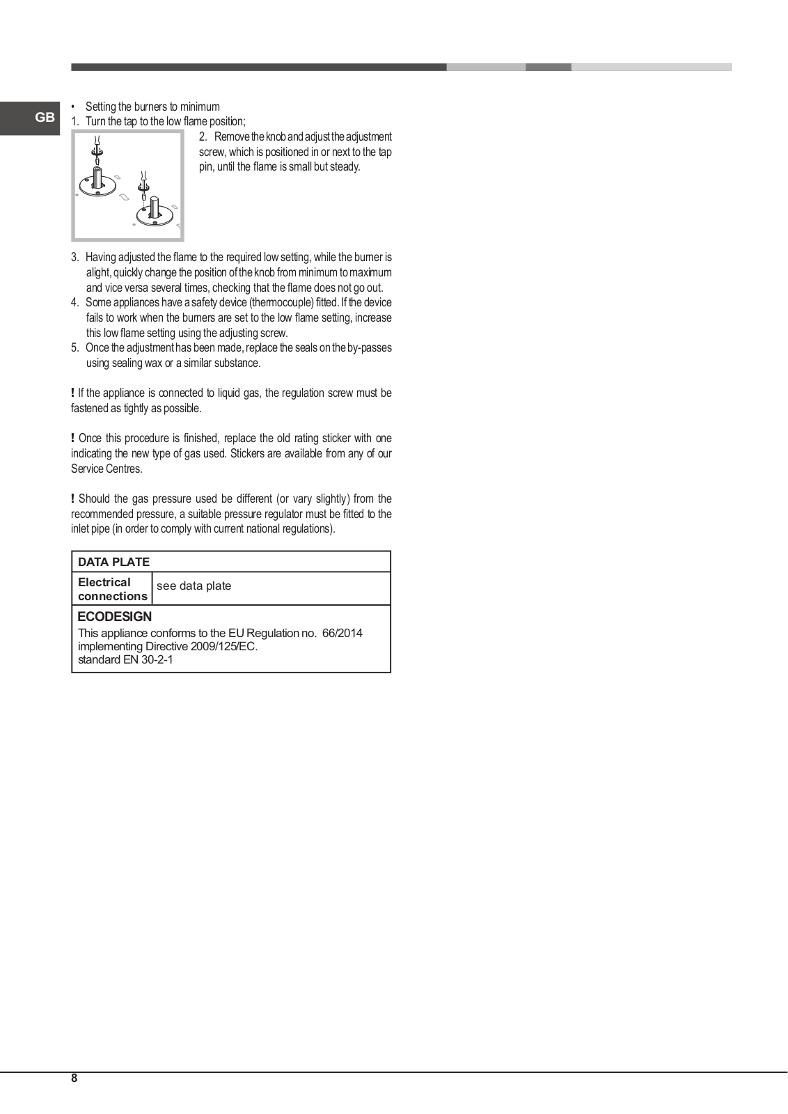
Setting the burners to minimum

1.

Turn the tap to the low flame position;


2. Removetheknobandadjusttheadjustment


screw, which is positioned in or next to the tap


pin, until the flame is small but steady.

3.Having adjusted the flame to the required low setting, while theburneris alight, quickly change the position of the knob from minimum to maximum and vice versa several times, checking that the flame does not go out.

4.Someapplianceshaveasafetydevice(thermocouple)fitted.Ifthedevice fails to work when the burners are set to the low flame setting, increase this low flame setting using the adjusting screw.

5.Once the adjustment has been made, replace the seals on the by-passes using sealing wax or a similar substance.

!If the appliance is connected to liquid gas, the regulation screw must be fastened as tightly as possible.

!Once this procedure is finished, replace the old rating sticker with one indicating the new type of gas used. Stickers are available from any of our Service Centres.

!Should the gas pressure used be different (or vary slightly) from the recommended pressure, a suitable pressure regulator must be fitted to the inlet pipe (in order to comply with current national regulations).

DATA PLATE

Electrical

see data plate

connections

ECODESIGN

This appliance conforms to the EU Regulation no. 66/2014 implementing Directive 2009/125/EC.

standard EN 30-2-1

8

Loading...
+ 16 hidden pages