

Page 1
Merloni Elettrodomestici
Service Manual
WASHING MACHINE 2000
Language Issue/Edition Page
GB 2001-04-23/01 1-56
Page 2
Merloni Elettrodomestici
Service Manual
WASHING MACHINE 2000
Language Issue/Edition Page
GB 2001-04-23/01 2-56
Page 3
5
12
13
14
15
16
Merloni Elettrodomestici
Contents
1 CONTROL PANEL
1.1 Timer Selector 5
1.2 Timer Delay Setting 6
1.3 Buttons 10
1.4 Detergent drawer 11
2 SPECIAL PROGRAMMES
3 WASH CYCLE PERFORMANCE AND DURATION
4 PARTICULAR PHASES
5 BLEACH - STAIN REMOVAL BUTTON
6 ELECTRONIC CARD
6.1 Removing the EEprom 19
6.2 The Hardware key 21
6.3 Autotest 23
6.4 List of Faults LVB 2000 and procedures to follow to solve the problems 24
7 CONDUCTIVITY SENSOR
Service Manual
WASHING MACHINE 2000
28
Language Issue/Edition Page
GB 2001-04-23/01 3-56
Page 4
29
Merloni Elettrodomestici
8 DISMANTLING AND REPLACING COMPONENTS
8.1 Top 29
8.2 Microdelayer 30
8.3 Control panel 32
8.4 Top Counterweight 35
8.5 Front counterweight 35
8.6 Driven Pulley 37
8.7 Engine 39
8.8 Temperature Probe 41
8.9 Programme Selector 42
8.10 Door Seal 44
8.11 Module 45
8.12 Door Handle 45
8.13 Drainage Pump 46
8.14 Shock absorbers 47
8.15 Enlarged Wash Dry 48
Service Manual
WASHING MACHINE 2000
Language Issue/Edition Page
GB 2001-04-23/01 4-56
Page 5
4
7
Merloni Elettrodomestici
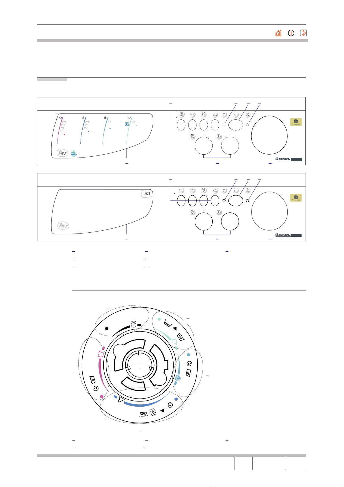
1 CONTROL PANEL
Fig. 1 Model AL68XIT Control Panel and Model AL109XIT Control Panel
2
5
3
6
1
3
5
2
4
1
11,3
60˚
40˚
40˚
COTTON
90˚
4
energy
1
normal
2
3
40° class A
delicate coloured
stop/reset
60˚
5
40˚
6
daily 300‘
7
stop/reset
energy
delicate
WOOL-CACHEMIRESYNTHETIC
40˚ 30˚
89
hand
wash
stop/reset
SILK-CURTAIN
extra delicate
stop/reset
5
15,40
6 7
1
15,40
1 Buttons Option
Door Lock Led
ON/OFF
5
StandBy/O Led
Detergent Drawer
Component Knobs
6 7
2 3 4
ON
OFF
2 3 4
ON
OFF
Programme Selector
MARGHERITA 2000
AL68X
digital
MARGHERITA 2000
AL109X
digital
1.1 Timer Selector
Fig. 2
1
1h
1
2
3
2
4
5
Timer Delay
Cotton
3h
6
6h
12h
7
3
Synthetic
Wool
5
9
4
8
Silk/Curtains
Service Manual
WASHING MACHINE 2000
Language Issue/Edition Page
GB 2001-04-23/01 5-56
Page 6
Merloni Elettrodomestici
Led
There are three ON-StandBy led management modes:
A. StandBy mode: the user is informed when the machine is not carrying out
a programme; this flashing mode is active after stopping and resetting. The
led flashes at a frequency of about 1 Hz
B. Programme Acceptance Mode: the led flashes for about 3" at a frequency
of 10 Hz
C. ON mode: the led is always alight
Programme Setting
Normal programme setting:
• The machine starts from a StandBy position (led in mode A)
• The user selects a programme
• If the selector remains in the same position for at least 5" the machine
passes to the programme acceptance mode (led in mode B) and then to
ON (led in mode C)
• At this point the programme starts
• It does not change if the selector position is modified
• The user can stop the cycle by moving to the Reset position (marked with
a dot)
1.2 Timer Delay Setting
• The machine starts from a StandBy position (led in mode A)
• The user turns the selector to the desired delay
• If the selector remains in the same position for at least 5" the machine
passes to the delay acceptance mode (led in mode B) and then to ON (led
in mode C)
• The user selects a programme
• If the selector remains in the same position for at least 5" the machine
passes to the programme acceptance mode (led in mode B) and then to
ON (led in mode C)
• It is not changed if the selector position is modified
• The user can stop the delay count by moving to one of the Reset positions
for at least 5" (marked with a dot on the programme disc)
• When the count down is completed the machine starts its cycle and passes
to ON (led in mode C)
• It is not changed if the selector position is modified
• The user can stop the cycle by moving to one of the 5 Reset positions for
at least 5"
Service Manual
WASHING MACHINE 2000
Language Issue/Edition Page
GB 2001-04-23/01 6-56
Page 7
Merloni Elettrodomestici
By resetting a programme the machine returns to the StandBy position (led in
mode A).
The Door Lock led is only a user feedback to know when it is possible to
open the door.
Even if the power supply is interrupted the programme that has been selected re-
N.B.
mains.
1.2.1 Wash Intensity Knob
Fig. 3
R
This knob allows the characteristics of the selected wash programme to be
changed. By turning it the wash becomes more intensive and the programme
duration increases (Relative symbols).
By turning it ANTICLOCKWISE the wash becomes more delicate and the cycle
duration decreases.
N.B.
It can be used only with the programmes for resistant and synthetic fabrics, except 3 and 7 (see timer selector).
Service Manual
WASHING MACHINE 2000
Language Issue/Edition Page
GB 2001-04-23/01 7-56
Page 8
Merloni Elettrodomestici
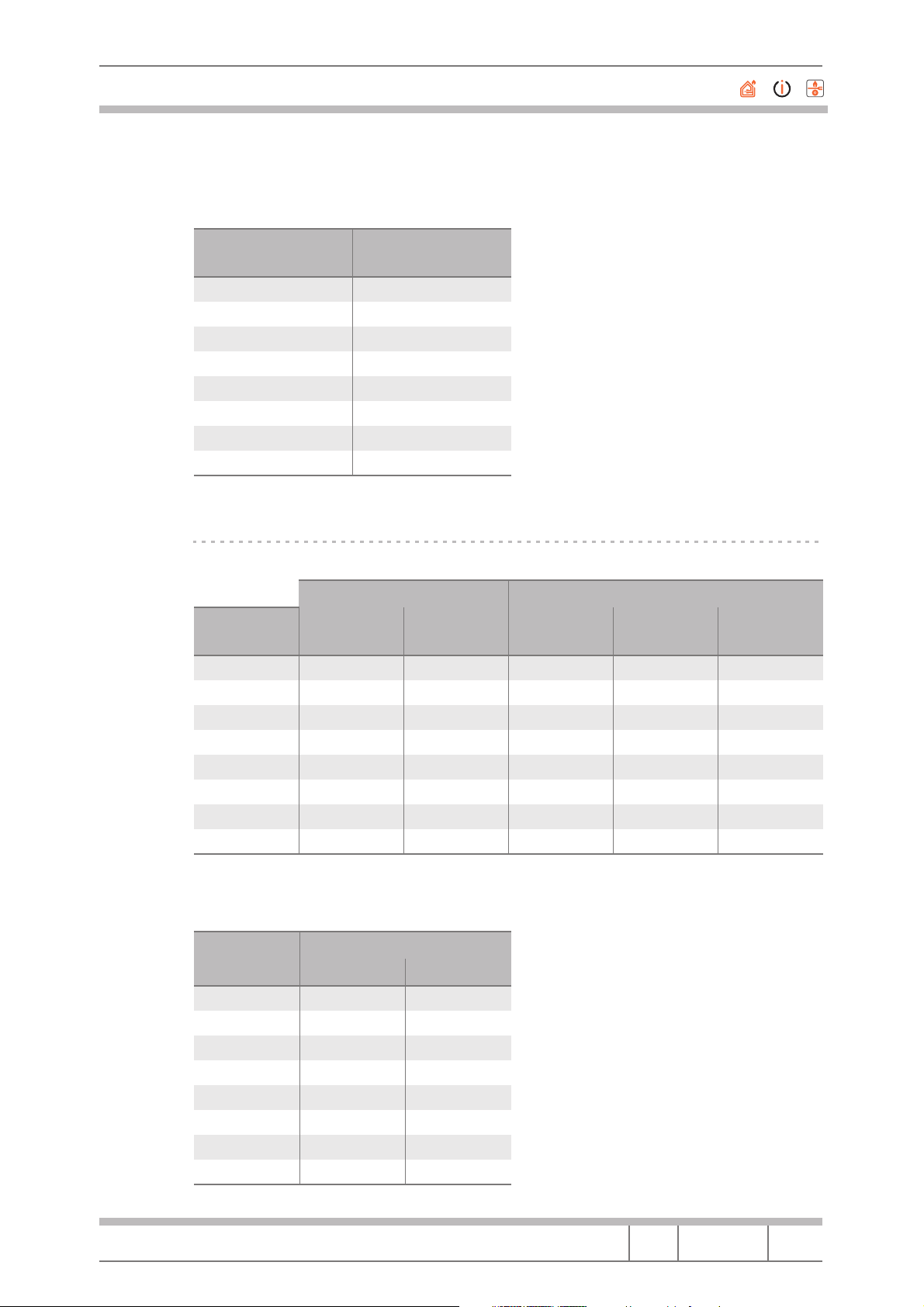
The total duration reduction specification regarding the IEC cycle is the following:
Location Reduction
1
2 20
3 17
4 13
5 10
6 6
7 3
8 0
%
30
1
The time variation set with the knob is the following:
IEC cycle 60˚
Cycle Steps
Location Time Decrease
%
94
2
3
4
5
6
7
8
106
111
116
121
126
130
134
30
20
17
13
10
6
3
0
Decrease
%
73
50
41
32
24
15
7
0
Mech
(Min)
Biol
(Min)
12.2 2.7
22.5 5.0
26.6 5.9
30.6 6.8
34.2 7.6
38.3 8.5
41.9 9.3
45.0 10.0
In relation to the movements the knob action is the following (difference
compared to standard setting):
Location
1
Handling Procedures
ON [s] OFF [s]
–4 +4
2 –3 +3
3 –2 +2
4 –1 +1
5 0 0
6 0 0
7 0 0
8 0 0
Service Manual
WASHING MACHINE 2000
Language Issue/Edition Page
GB 2001-04-23/01 8-56
Page 9
Merloni Elettrodomestici
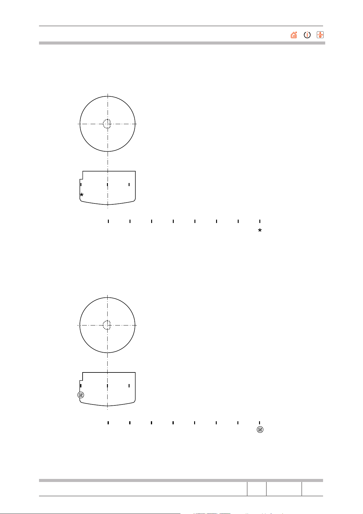
1.2.2 Temperature Adjustment Knob
Fig. 4
max
max807060504030
80
This knob is used to reduce the programme recommended temperature until
giving a cold wash.
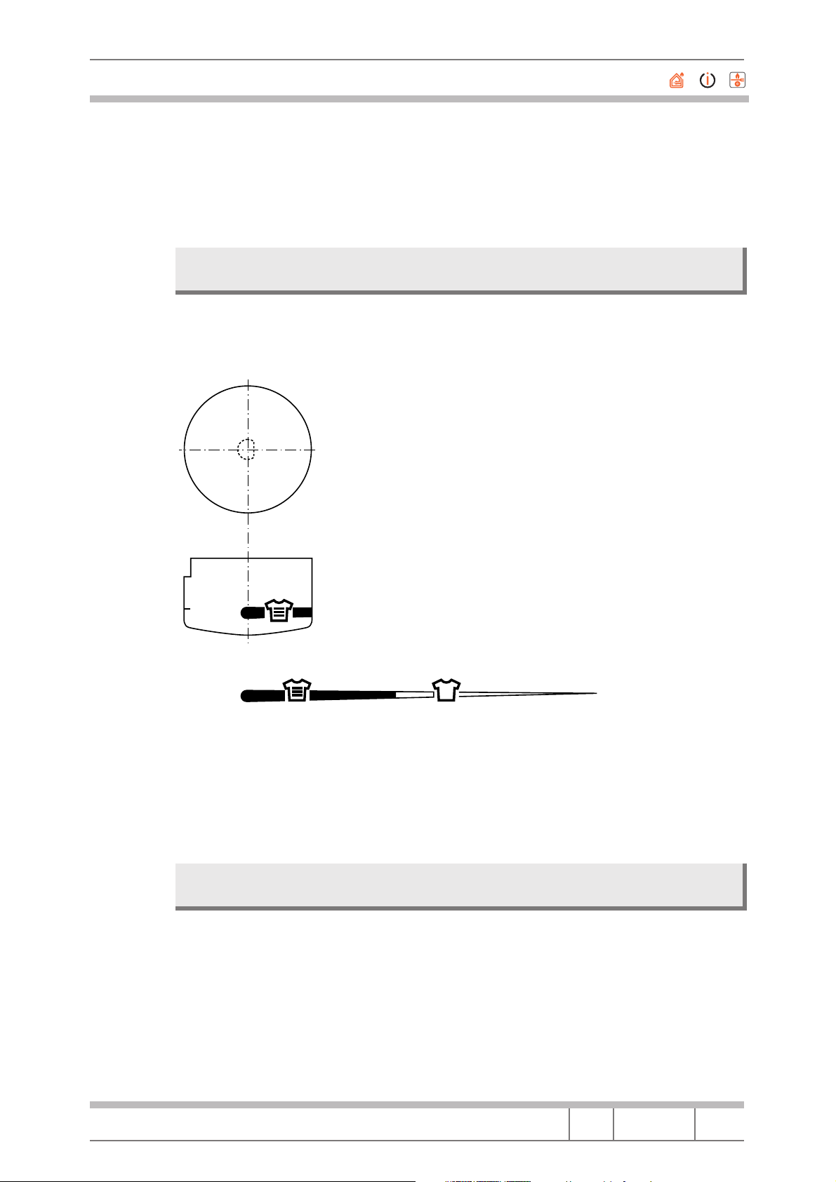
1.2.3 Spin Speed Adjustment Knob
Fig. 5
This knob is used to reduce the spin speed, until reaching no spin.
Service Manual
WASHING MACHINE 2000
1000
900
9001000 800 700 600 500 400
Language Issue/Edition Page
GB 2001-04-23/01 9-56
Page 10
Merloni Elettrodomestici
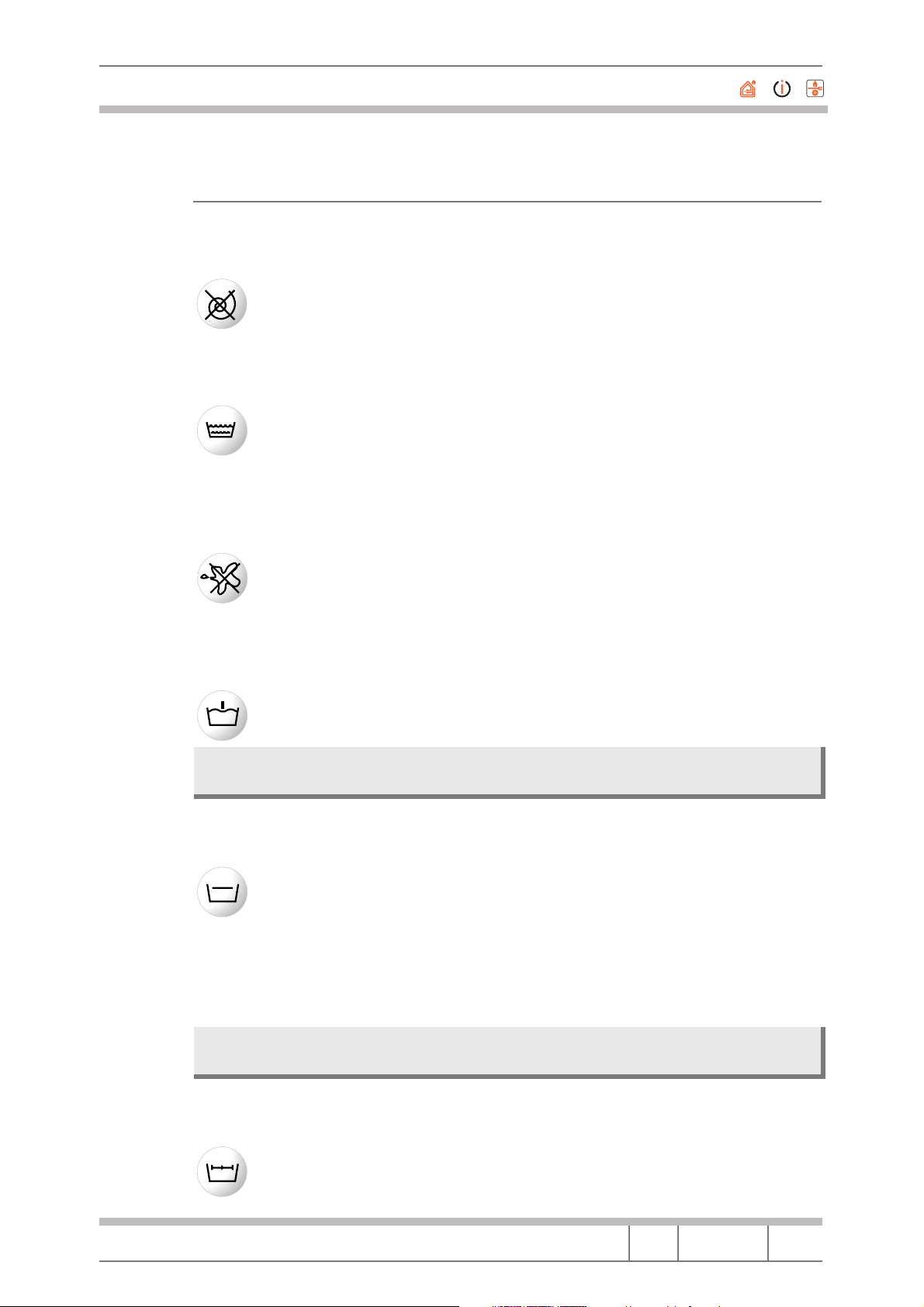
1.3 Buttons
1.3.1 No spin button
By pressing this button the washing machine does not spin, but rotates
the basket at moderate speed. It should be used when the garments
that are being washed are difficult to iron.
1.3.2 Extra rinse button
This button is used to increase the number of rinses in the programmes for resistant fabrics. It is recommended that this should be
used to improve the rinse when the machine has a full load and a lot
of detergent.
1.3.3 Stain removal button
By pressing this button the washing machine performs a more intensive
wash that improves the effectiveness of liquid additives (see chap. 5
BLEACH - STAIN REMOVAL BUTTON) thus allowing elimination of
even the most resistant stains.
1.3.4 Prewash button
This button allows a prewash to be performed in all programmes EXCEPT wool.
N.B. When using this function the bleach cycle cannot be performed (Stain removal
button).
1.3.5 Anti-crease button
When this button is combined with programmes for synthetic fabrics
and silk/curtains it interrupts the wash programme leaving the garments to soak before draining.
This function is important as it avoids creasing delicate and synthetic
fabrics (e.g. when it is not possible to take the laundry out at the end
of the wash but only a few hours later). The programme can be completed by excluding the button.
N.B. If the machine is not provided with this button the programme can be completed
by turning the selector knob one notch.
1.3.6 Rapid Button
Press this button to reduce the wash programme duration by about
30%. It cannot be used with special programmes and with those for
wool and silk.
Service Manual
WASHING MACHINE 2000
Language Issue/Edition Page
GB 2001-04-23/01 10-56
Page 11
Merloni Elettrodomestici
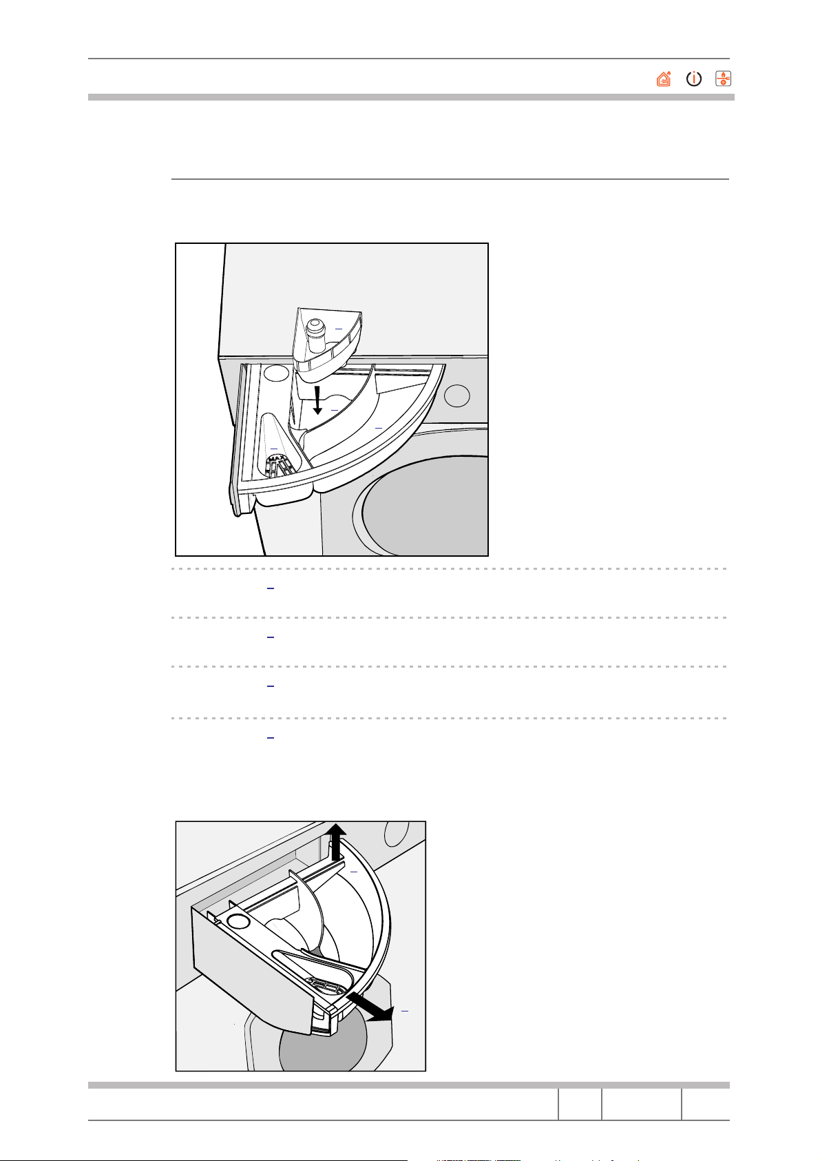
1.4 Detergent drawer
The detergent drawer can be opened by rotating it outwards. Pour the detergent and the additive, if any, following the detergent dosage indications.
Fig. 6
X
A
M
3
4
1
2
Fig. 7
Compartment 1
Prewash detergent (powder).
Compartment 2
Wash detergent (powder or liquid).
Compartment 3
Softeners, …
Compartment 4
Bleach and delicate bleach.
The detergent drawer is extractable. To remove it pull it upwards and then
outwards as shown in the following figure.
1
Service Manual
WASHING MACHINE 2000
2
Language Issue/Edition Page
GB 2001-04-23/01 11-56
Page 12
Merloni Elettrodomestici
2 SPECIAL PROGRAMMES
40° AS 60°
It is a special programme that allows very good washing results to be obtained even at low temperatures.
By setting programme 3 at 40 ˚C and thanks to a special action of the washing
machine and an increase of the washing time, the results will be the same as
washing at 60 ˚C.
N.B. When using this programme the Intensive/Delicate knob is not active.
Daily
This machine has a programme for daily washing.
By setting programme 7 at 30 ˚C it is possible to wash lightly soiled garments
together, even if they are of different types and colours (max 3 KG).
This programme allows savings in time and energy because the cycle lasts
about 30 minutes.
N.B. Liquid detergent is recommended.
Service Manual
WASHING MACHINE 2000
Language Issue/Edition Page
GB 2001-04-23/01 12-56
Page 13
Merloni Elettrodomestici
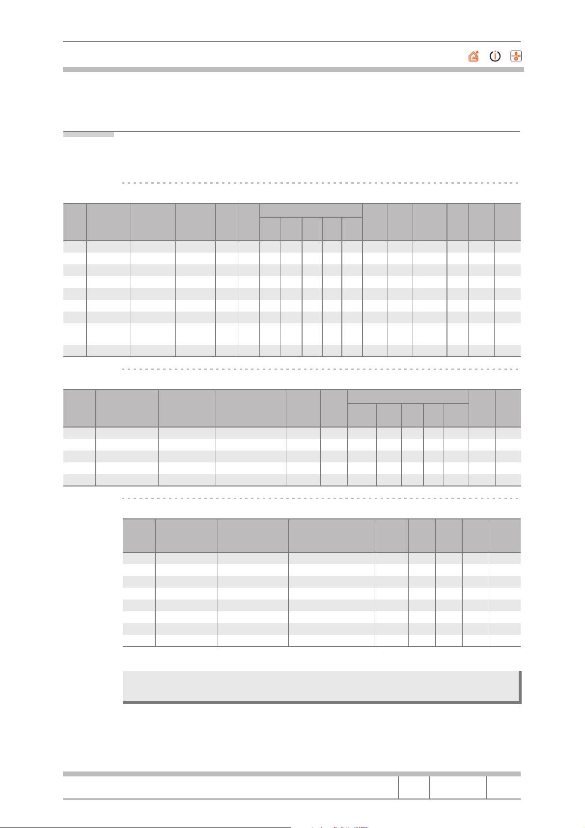
3 WASH CYCLE PERFORMANCE AND DURATION
Tab. 1 MODEL AL68XIT
Performance summary of all the Standard wash cycles
Start
Progr.
Cycle LoadkgDetergent Wash
1 90˚ Cotton 5 (Cotton) IEC (134 g) 87 '147 '67.4 57.0 39.0 79.4 60.7 15.3 nd 1.09 1.57 A E
2 60˚ Cotton 5 (Cotton) IEC (134 g) 82 '134 '62.4 55.8 37.9 76.1 58.1 15.2 nd 1.05 0.95 A A
3 40˚ = 60˚ 5 (Cotton) IEC (134 g) 108 '163 '60.8 56.8 39.0 76.1 58.2 15.4 nd 1.05 0.74 A A
4 40˚ Cotton 5 (Cotton) IEC (134 g) 39 '95 '47.1 47.8 31.5 69.3 48.9 15.4 nd 0.88 0.50 F A
5 60˚ Synth. 2.5 (Ter/Cot) IEC ( 94 g) 61 '102 '66.0 56.5 40.4 76.7 59.9 8.5 35.1 1.08 0.68 A D
6 40˚ Synth. 2.5 (Ter/Cot) IEC ( 94 g) 33 '73 '55.9 52.7 34.6 68.9 53.0 9.3 36.7 0.95 0.37 D A
7 30˚ Daily 3 (Cotton) IEC (102 g) 16 '34 '35.4 46.7 32.1 61.3 43.9 11.2 31.2 0.80 0.21 G A
7 30˚ Daily 3 (Cotton) Dash liq.
(120 g)
9 30˚ Silk 1 (Ter/Cot) IEC (120 g) 31 '54 '47.5 47.8 32.5 62.0 47.5 20.1 72.4 0.86 0.39 G F
Cy-
Soiled Garment Reflectance Wash
Dur.
cle
Blood Choc.
Dur.
16 '34 '47.1 48.6 31.6 56.8 46.0 11.2 31.2 0.84 0.20 G A
Milk
Coal
Oil
Wine Total
Water
Total
Water
Ratio
Wascator
Ener-
gy
kWh
Wash
Class
Wash cycle performance using the stain button
Start
Progr.
1 90˚ Cotton 5 (Cotton) Ace (150 cc) 96 '175 '70.1 68.4 40.3 80.7 64.8 16.2 74.0
2 60˚ Cotton 5 (Cotton) Ace (150 cc) 86 '160 '60.7 68.2 37.5 80.1 61.6 14.9 74.0
4 40˚ Cotton 5 (Cotton) Ace (150 cc) 52 '125 '50.6 49.4 31.9 78.4 52.6 16.3 72.4
5 60˚ Synthetics 2.5 (Ter/Cot) Ace gent. (150 g) 76 '134 '70.1 61.3 41.8 77.1 62.6 9.7 48.5
6 40˚ Synthetics 2.5 (Ter/Cot) Ace gent. (150 g) 47 '100 '58.3 55.6 37.0 73.5 56.1 9.4 47.8
Cycle Load
kg
Additive Wash
Duration
Cycle
Dura-
tion
Soiled Garment Reflectance Wash
Blood Choc.
Milk
Coal
Oil
Wine Total
Water
Ener-
gy
Class
Total
Water
Wash intensity knob functionality
Start
Progr.
1 60˚ Cotton 5 (Cotton) 1 - Minimum 42 '94 '15.0 nd 0.80
2 60˚ Cotton 5 (Cotton) 5 - Recommended 61 '113 '14.3 nd 0.85
4 40˚ Cotton 5 (Cotton) 1 - Minimum 22 '74 '14.5 nd 0.51
4 40˚ Cotton 5 (Cotton) 5 - Recommended 34 '107 '14.5 nd 0.57
5 60˚ Synthetics 2.5 (Ter/Cot) 1 - Minimum 34 '70 '9.1 38.1 0.66
5 60˚ Synthetics 2.5 (Ter/Cot) 5 - Recommended 51 '86 '8.4 38.3 0.70
6 40˚ Synthetics 2.5 (Ter/Cot) 1 - Minimum 20 '53 '7.2 38.9 0.34
6 40˚ Synthetics 2.5 (Ter/Cot) 5 - Recommended 30 '65 '8.5 38.9 0.39
N.B. In the other models duration of the cycle corresponding to the rapid button is the
Service Manual
WASHING MACHINE 2000
Cycle Load
kg
Knob
Position
Wash
Duration
Cycle
Dura-
tion
same as that obtained with the wash intensity knob in position 1.
Language Issue/Edition Page
GB 2001-04-23/01 13-56
Wash
Water
Total
Water
Energy
kWh
Page 14

Merloni Elettrodomestici
4 PARTICULAR PHASES
Antishock
In the event that the machine goes to a draining phase (e.g. Spin) and the water temperature is higher than the set limit (e.g. 60˚), the machine performs a
particular cycle before draining:
e.g.
1. Load 5 litres from Wash SV
2. Move 5" ON, 5" OFF, 25 rpm per 4'
3. If Temperature > Limit go to 1 otherwise go to 4
4. Drain + Spin
Antifoam
If there is too much foam in the machine during the spin it will carry out the
following cycle:
1. Stop for 2'
2. Load 10 litres from Wash SV
3. Move 5" ON, 5" OFF, 25 rpm per 2'
4. Restart the Spin that was interrupted at the beginning
This procedure is repeated until the foam problem is solved.
Service Manual
WASHING MACHINE 2000
Language Issue/Edition Page
GB 2001-04-23/01 14-56
Page 15
Merloni Elettrodomestici
5 BLEACH - STAIN REMOVAL BUTTON
In case of bleaching it is necessary to insert an extra chamber 4 in the deter-
1; when pouring the bleach be careful not to ex-
Fig. 8
gent drawer compartment
ceed the max level indicated in the following figure.
X
A
M
X
A
M
This washing machine is provided with a special function TO BE USED FOR
BLEACHING (Stain removal button).
When bleaching is carried out separately pour the bleach into the supplementary chamber
4, press the stain removal button, switch the machine on and turn
the selector to the rinse position after programme 4.
When bleaching is carried out during a normal washing cycle, pour the detergent and the additives into the appropriate compartments, press the stain removal button, switch the machine on and select the desired washing cycle.
N.B. Bleaching is not possible with the silk programme.
When the bleach chamber is used it is not possible to use the prewash function.
Service Manual
WASHING MACHINE 2000
Language Issue/Edition Page
GB 2001-04-23/01 15-56
Page 16
Merloni Elettrodomestici
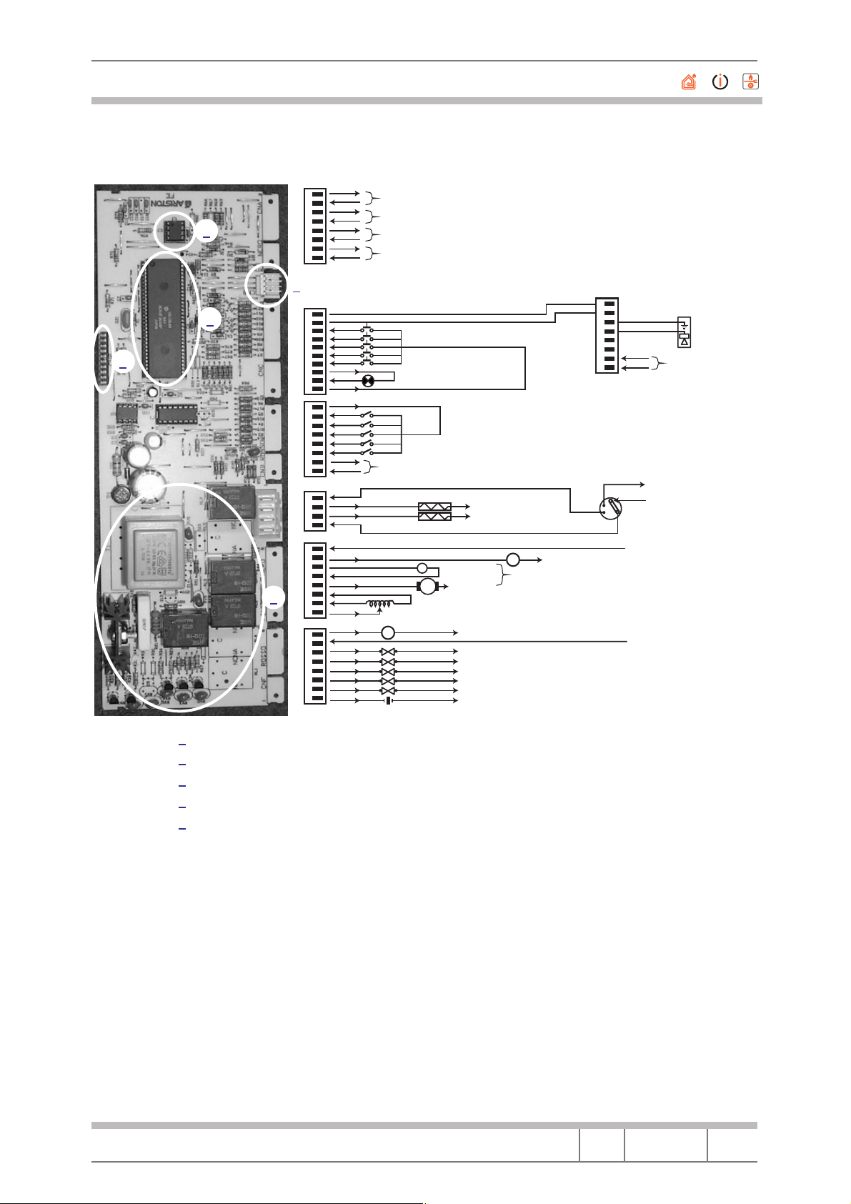
6 ELECTRONIC CARD
The card inside the machine:
Fig. 9
1
1
The position of the card inside the machine is the usual electronic module position
Service Manual
WASHING MACHINE 2000
Language Issue/Edition Page
GB 2001-04-23/01 16-56
Page 17
Merloni Elettrodomestici
Fig. 10
8
7
C
6
5
N
2
4
3
2
A
1
1
3
4
10
9
8
C
7
6
N
5
4
3
C
2
1
8
7
C
6
5
N
4
3
D
2
1
C
4
3
N
2
1
1
8
7
C
6
5
N
4
3
5
2
E
1
8
7
C
6
5
N
4
3
F
2
1
Variable or switch resistance. Potentiometer or Exterior key button. Between 0 VCC and XXVCC
Variable or switch resistance. Potentiometer or Exterior key button. Between 0 VCC and XXVCC
NTC of Drying Cycle. 15°C xxVCC; xxΩ; 20°C xxVCC; xxΩ; 30°C xxVCC; xxΩ; 40°C xxVCC; xxΩ;
NTC of Washing Cycle. 15°C xxVCC; xxΩ; 20°C xxVCC; xxΩ; 30°C xxVCC; xxΩ; 40°C xxVCC; xxΩ;
Key button +XVCC
Pilot ON/Standby +XVCC/XΩ
+XVCC
“Timer” Motor xxVAC; XXΩ
Wash Cycle Resistance
Neutral
Neutral
Dryer Cycle Resistance
T
Dryer Fan
MV
EV Pre-wash
EV Hot water
EV Wash cycle
EV Drying cycle
EV Water stop
Micro door
Emptying Pump
Tachometer
M
Phase 220 V
Phase 220 V
Fase 220 V
Phase 220 V
Phase 220 V
Phase 220 V
Phase 220 V
Phase 220 V
Phase 220 V
Phase 220 V
From +XmVCC
To +XmVCC
Full Level
Empty Level
PS
Motor
Earth
Phase 220 V
16
14
8
7
6
5
4
3
2
1
Overflow
Earth
From +XmVCC
To +XmVCC
Emptying Pump
11
Neutral 220 VAC
12
PRESSURE SENSOR
Phase 220 VAC
Neutral 220 V
Conductivity
Sensor
220 VAC Direct
1 Digital Connection WRAP
2 EEPROM
3 Microprocessor
4 Serial Connection
5 Power Zone
Service Manual
WASHING MACHINE 2000
Language Issue/Edition Page
GB 2001-04-23/01 17-56
Page 18

Merloni Elettrodomestici
Tab. 2 NTC temperature positioned in tub valid for washing cycle and wash dry cycle
CHARACTERISTICS
T° (°C)
R (Ω)
Agitated Water
Min
B = 4263
25 18.80 K 20.00 K
80 2.03 M 2.23 K
Tab. 3 NTC temperature positioned on the washing cycle resistance
T° (°C)
Agitated Water
R. min R. max
R (Ω)
25 °C 19600 20400
30 °C 15710 16470
60 °C 4737 5149
80 °C 2362 2622
90 °C 1713 1919
100 °C 1261 1427
Card Replacement
The card is a neutral element, in the sense that the component is not tied to a
particular line graph or a particular machine.
Max
B = 4200
Fig. 11
The card is customised using the EEProm, so that should it be necessary to replace the card, the EEProm must be removed from the old card and the same
EEProm will have to be fitted on the new card before remounting it in the machine.
1
1 Digital Connection
Service Manual
WASHING MACHINE 2000
Language Issue/Edition Page
GB 2001-04-23/01 18-56
Page 19

Merloni Elettrodomestici
6.1 Removing the EEprom
First of all, pay attention to which side the EEProm is mounted. There are two
reference marks,
mounted.
Fig. 12
Ref. A and Ref. B, that must be aligned when the EEProm is re-
Ref. A
1
Fig. 13
Ref. B
The EEProm is extracted with a specific device. The EEProm must be extracted as shown in the figure.
Service Manual
WASHING MACHINE 2000
Language Issue/Edition Page
GB 2001-04-23/01 19-56
Page 20

Merloni Elettrodomestici
The extracted EEProm must be remounted as shown in the figure, always using the specific device.
Fig. 14
Service Manual
WASHING MACHINE 2000
Language Issue/Edition Page
GB 2001-04-23/01 20-56
Page 21

Merloni Elettrodomestici
6.2 The Hardware key
The hardware key is a tool that puts the pc into contact with the machine or
that forces the machine to perform the self-test cycle (the operation must be
performed by turning the small switch on the device to TEST for at least 5";
the machine carries out a set cycle described in position 35 of the line graph).
Fig. 15
1 Slot for introduction of the HW key
Service Manual
WASHING MACHINE 2000
1
Language Issue/Edition Page
GB 2001-04-23/01 21-56
Page 22

Merloni Elettrodomestici
Fig. 16
Fig. 17
Service Manual
WASHING MACHINE 2000
Language Issue/Edition Page
GB 2001-04-23/01 22-56
Page 23

Merloni Elettrodomestici
6.3 Autotest
Should the washing machine not be found to be in error, it is possibile to
check by means of a Hardware key and using a specific autotest cycle, activated as follows:
1. Take LB to reset (coloured ball) for at least 5" and wait for the led to flash
in reset mode
2. Insert the hardware key through the serial socket
3. Turn the switch on the serial key to Test
4. Wait for the hatch to lock and the switch to start turning.
5. Turn the switch on the serial key to PC
The machine will carry out the following cycle:
• The switch will turn to position 0 (12h if the machine has a delay, programme 1 if the machine does not have a delay)
• Wash solenoid valve loads for approx. 10"
• Pre-wash solenoid valve loads for approx. 10"
• Wash and pre-wash solenoid valves load at the same time until the pressure switch is complete
• Heats up to 30° and moves the motor in both directions
• Moves the switch forward by 9 turns
• Unloads and spins
• The switch will turn to one of the reset positions
• STOP
The test cycle can be repeated as many times as necessary using the same
method.
The test cycle can be stopped by turning the switch to one of the reset positions.
Service Manual
WASHING MACHINE 2000
Language Issue/Edition Page
GB 2001-04-23/01 23-56
Page 24

Merloni Elettrodomestici
6.4 List of Faults LVB 2000 and procedures to follow to solve the problems
For each fault the procedure must be followed step by step in order; obviously once the problem has been solved, the procedure must be stopped.
F01: Triac Short Circuit
1. Check effectiveness of contacts on the CNE connector card
2. Check for any water leaks that could reach the CNE contact
3. Check motor terminal board(for any problems due to attacks by chemical
work residues on the contacts)
4. Replace card
F02: Motor shutdown, Tachymeter in Short/Open
1. Check the effectiveness of contacts on CNE connector card
2. Overhaul motor connector
3. Check continuity of CNE/Motor connector
4. Check motor winding
5. Check Tachymeter winding
6. Replace card
F03: Detection of NTC Open/Short Circuit
1. Check the effectiveness of contacts on CAN connector card
2. Check NTC wiring
3. Check continuity of wiring in CNA/NTC connectors
4. Replace NTC
5. Replace card
F04: Detection of Overflow and Pressure Switch Vacuum at the same time
(Pressure Switch blocked on Vacuum)
1. Check the effectiveness of contacts on CN1 connector card
2. Overhaul Pressure Switch contacts
3. Check continuity of CN1 wiring/Pressure switch
4. Replace pressure switch
5. Replace card
Service Manual
WASHING MACHINE 2000
Language Issue/Edition Page
GB 2001-04-23/01 24-56
Page 25

Merloni Elettrodomestici
F05: detection of Blocked Pump or Pressure Switch stuck on Vacuum
1. Check the effectiveness of contacts on the CNF connecter card (pump con-
nector)
2. Overhaul the Pump Connector
3. Check Pump Filter
4. Check Pump winding
5. Change pump
6. Replace card
F06: Switch error (no code is found)
1. Check the effectiveness of contacts on the CND connector card(switch
connector)
2. Check effectiveness of Switch connector
3. Check continuity of Switch/CND
4. Check motor switch
5. Replace switch
6. Replace card
F07: Stuck resistance relay
1. Check effectiveness of contacts on CN1 connector card
2. Overhaul CN1
3. Overhaul resistance connection
4. Replace card
5. Overhaul resistance connection
6. Replace Card
F08: Detection of Lack of Resistance or Pressure Switch Stuck on Full
1. Check effectiveness of contacts on CN1 connector card
2. Overhaul Resistance Connector
3. Overhaul Pressure Switch Connector
4. Replace resistance
5. Replace Pressure Switch
6. Replace Card
F09: Detection of Machine Setup Error
1. Check Microprocessore Version
2. Request Eeprom Spare Part stating Microprocessor version
Service Manual
WASHING MACHINE 2000
Language Issue/Edition Page
GB 2001-04-23/01 25-56
Page 26

Merloni Elettrodomestici
F10: Detection of Pressure Switch Vacuum and Full or Pressure Switch neither Vacuum nor Full
1. Check the effectiveness of contacts on CN1 Connector Card
2. Overhaul Pressure Switch Wiring
3. Check continuity of CN1/Pressure Switch
4. Replace Pressure Switch
5. Replace card
F11: Detection of Absence of Pump Feedback
1. Check the effectiveness of contacts on the CN1 Connector Card
2. Check the effectiveness of contacts on the CNF Connector Card
3. Overhaul Pump Connector
4. Overhaul Pressure Switch Connector
5. Check pump Winding
6. Replace pump
7. Replace Card
F12: Lack of Display card-Main Card Communication
1. Check the effectiveness of contacts on CNC Connector Card
2. Overhaul 8-way connector on Display card
3. Check continuity of CNC-CN 8 way connector
4. Replace Main Card
5. Replace Display Card
F13: NTC wiring harness disconnected from the dryer system
1. Check the efficiency of the terminals on the CNA connector board
2. Check NTC wiring harness
3. Check the wiring harness continuity of the CNA / NTC connectors
4. Replace NTC
5. Replace terminal board
F14: Dryer connector open or not connected
1. Check the efficiency of the terminals on the CNI connector board
2. Overhaul CN1
3. Overhaul connector connection
4. Replace the board
Service Manual
WASHING MACHINE 2000
Language Issue/Edition Page
GB 2001-04-23/01 26-56
Page 27

Merloni Elettrodomestici
F15: Dryer connector is always active
1. Check the efficiency of the terminals on the CNI connector board
2. Overhaul connector connection
3. Overhaul the pressure sensor connection
4. Replace the connector
5. Replace pressure sensor
6. Replace the board
N.B. From Fault F01 to fault F11
These are shown by LEDs in stand by/on in LVB2000 machines Ariston/Indesit.
From fault F01 to fault F12
These are shown in a display located on the instrument panel of LVB2000 machines Evolution Indesit.
From fault F01 to fault F15
Are those that are indicated according to the version via LED stand by/on or
display positioned on the Wash Dry machine Ariston/Indesit panel.
6.4.1 Reading the Fault
The fault on the machine is shown by:
1. The continuous rotation of the switch
2. The activation for the first 4", of the solenoid valve and discharge pump
3. The hatch is blocked
4. The LED flashes:
the number of flashes is equal to the fault code; l code must be read as follows:
• Each rapid flash (2/3 very rapid flashes of the LED) represents a code
value.
• The fault code is assessed counting the number of flashes in a time of _
seconds one from the other.
• The count is stopped when the LB waits for approx. 8/9" between two
flashes.
• The procedure is repeated cyclically by the machine.
Fig. 18 Esp. F03
1
2 3
1 2/3 Rapid Flashes = 1 code
2
Approx. 4"
3 Approx. 8/9"
Service Manual
WASHING MACHINE 2000
Language Issue/Edition Page
GB 2001-04-23/01 27-56
Page 28

Merloni Elettrodomestici
7 CONDUCTIVITY SENSOR
Fig. 19
Service Manual
WASHING MACHINE 2000
Language Issue/Edition Page
GB 2001-04-23/01 28-56
Page 29

Merloni Elettrodomestici
8 DISMANTLING AND REPLACING COMPONENTS
CAUTION
When dismantling/replacing the tub components be careful not to lever on
the plate tub as it could be damaged irreparably.
8.1 Top
The top is snap fitted to the control panel at the front and is secured to the back
of machine with two screws from behind.
Fig. 20
To dismantle the top remove the screws and then slide it horizontally backwards.
Service Manual
WASHING MACHINE 2000
Language Issue/Edition Page
GB 2001-04-23/01 29-56
Page 30

Merloni Elettrodomestici
8.2 Microdelayer
1. Using a screwdriver, remove the ring fixing the gasket to the casing
Fig. 21
Fig. 22
2. Detach the door seal
Service Manual
WASHING MACHINE 2000
Language Issue/Edition Page
GB 2001-04-23/01 30-56
Page 31

Merloni Elettrodomestici
3. And with a Phillips screwdriver remove the two screws and replace the
component
Fig. 23
4. Refit the door seal on the machine and replace the ring fixing the gasket to
the casing
Service Manual
WASHING MACHINE 2000
Language Issue/Edition Page
GB 2001-04-23/01 31-56
Page 32

Merloni Elettrodomestici
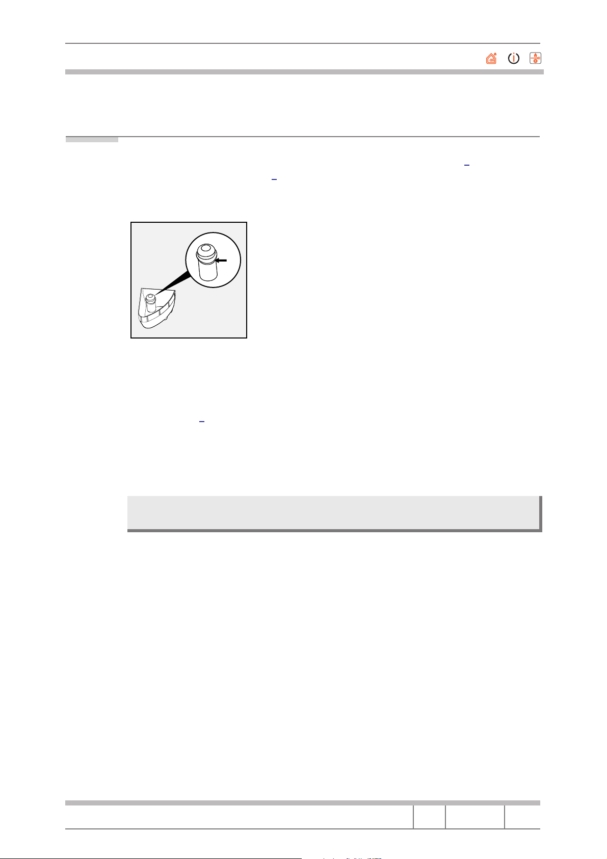
8.3 Control panel
1. Remove the top
2. Extract the component knobs and the programme selector knob lid
3. Remove the internal screw of the programme selector knob
4. Extract the programme selector push-push mechanism
5. Open the detergent drawer and press on the point indicated in the photo
to release it
Fig. 24
and then extract the detergent drawer
Fig. 25
Service Manual
WASHING MACHINE 2000
Language Issue/Edition Page
GB 2001-04-23/01 32-56
Page 33

Merloni Elettrodomestici
6. Remove the two hopper screws and the two control panel screws
Fig. 26
7. With a Phillips screwdriver dismantle the potentiometers
Service Manual
WASHING MACHINE 2000
Language Issue/Edition Page
GB 2001-04-23/01 33-56
Page 34

Merloni Elettrodomestici
8. With a screwdriver lever to release the switch
Fig. 27
By pulling the switch release it from the button
Then remove the ON/OFF indicator and the micro opening indicator
9. Extract the programme selector by removing the three screws that secure
the bracket to the control panel, and recover the buttons that will be used
in the new control panel
To reassemble, perform the above operations in reverse order.
Service Manual
WASHING MACHINE 2000
Language Issue/Edition Page
GB 2001-04-23/01 34-56
Page 35

Merloni Elettrodomestici
8.4 Top Counterweight
With a 13 mm hexagonal wrench remove the two screws and extract the
counterweight.
Fig. 28
8.5 Front counterweight
After extracting the swing element from the casing (see dismantling the TUB
CROSS) remove the 8 screws.
Fig. 29
Service Manual
WASHING MACHINE 2000
Language Issue/Edition Page
GB 2001-04-23/01 35-56
Page 36

Merloni Elettrodomestici
and extract the counterweight.
Fig. 30
Should it be difficult to extract, lever it with a screwdriver in correspondence
with the anchor points of the counterweight to the tub.
Service Manual
WASHING MACHINE 2000
Language Issue/Edition Page
GB 2001-04-23/01 36-56
Page 37

Merloni Elettrodomestici
8.6 Driven Pulley
1. Remove the back panel
2. Remove the drive belt
3. Remove the screw on the pulley with a TORX T40 wrench, by blocking the
pulley rotation movement
Fig. 31
Bearing in mind that the screw was fixed originally using a sealing material, it
might be difficult to release it.
Service Manual
WASHING MACHINE 2000
Language Issue/Edition Page
GB 2001-04-23/01 37-56
Page 38

Merloni Elettrodomestici
4. Lever with two screwdrivers and extract the pulley
Fig. 32
In order to ensure that the screw is properly locked it is advisable to apply a
drop of Loctite 270 (cod. 001109) on the thread.
Once it is fixed thoroughly wait for 3 hours before using the washing machine.
Service Manual
WASHING MACHINE 2000
Language Issue/Edition Page
GB 2001-04-23/01 38-56
Page 39

Merloni Elettrodomestici
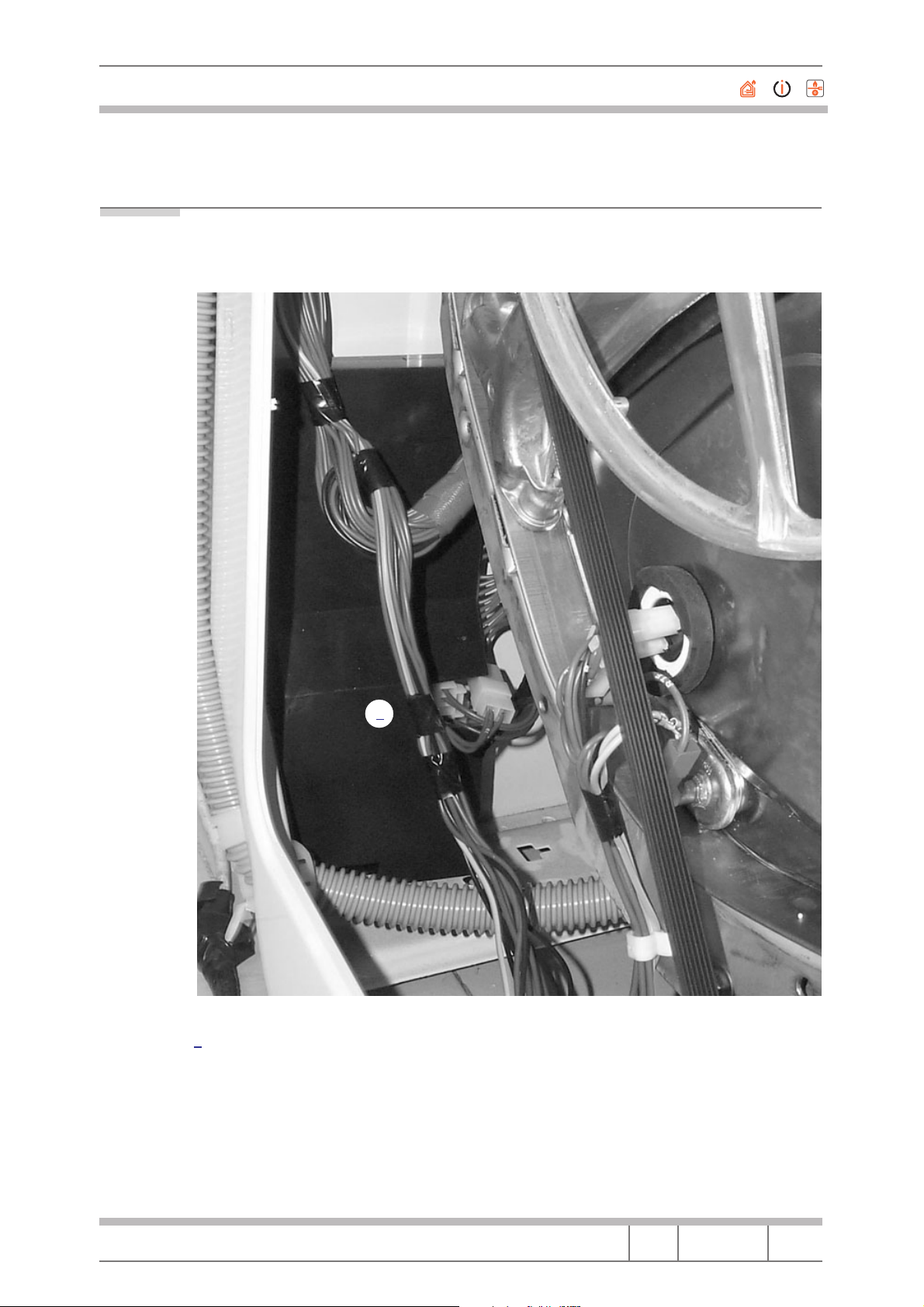
8.7 Engine
1. Remove the back panel
2. Tilt the machine forwards and lean it in a stable manner. Be careful not to
damage the electrical components on the control panel or the microdelayers
3. Dismantle the drive belt
4. Disconnect the motor from the wiring by extracting the terminal board and
disconnect the earth wire
Fig. 33
Service Manual
WASHING MACHINE 2000
Language Issue/Edition Page
GB 2001-04-23/01 39-56
Page 40

Merloni Elettrodomestici
5. Remove the two 8 mm self-threading hexagonal screws.
Fig. 34
Fig. 35
6. Lower the motor and push it towards the back of the machine to extract it
Recover the three rubber elements and the 2 plastic supports that will be used
for the new motor.
To reassemble, perform the above operations in reverse order.
Service Manual
WASHING MACHINE 2000
Language Issue/Edition Page
GB 2001-04-23/01 40-56
Page 41

Merloni Elettrodomestici
8.8 Temperature Probe
1. Remove the back panel
2. Extract the faston
3. Extract the probe with a screwdriver
Fig. 36
Service Manual
WASHING MACHINE 2000
Language Issue/Edition Page
GB 2001-04-23/01 41-56
Page 42

Merloni Elettrodomestici
8.9 Programme Selector
1. Remove the TOP
2. Dismantle the knob and the push-push mechanism by following the operations in paragraph 8.3 Control panel
3. Disconnect the programme selector terminal board
4. Locate the programme disk as shown in the photo
Fig. 37
and press the clamp as shown in the photo, then slide the selector upwards.
Service Manual
WASHING MACHINE 2000
Language Issue/Edition Page
GB 2001-04-23/01 42-56
Page 43

Merloni Elettrodomestici
5. Finally, extract the selector by pulling it towards the inside of the machine
When remounting the selector make sure that the clamping guides are correctly aligned with the programme selector plate support as shown in the
following photo.
Fig. 38
To complete assembly perform the above operations in reverse order.
Service Manual
WASHING MACHINE 2000
Language Issue/Edition Page
GB 2001-04-23/01 43-56
Page 44

Merloni Elettrodomestici
8.10 Door Seal
1. Prize off the front seal ring by inserting a small screwdriver between the ring
and the seal and using it as a lever
Fig. 39
Fig. 40
2. Free the seal from the machine and push it towards the inside of the basket
3. Tilt the machine backwards and lean it on a stable support
4. Release the door ring from the door opening on the casing, using the usual
thin-nose pliers (cod. 57902) (see Fig. 40 and Fig. 41)
Service Manual
WASHING MACHINE 2000
Language Issue/Edition Page
GB 2001-04-23/01 44-56
Page 45

Merloni Elettrodomestici
Fig. 41
5. Remove the seal
To mount fit the seal onto the lip of the tub lid, checking that the seal is located correctly. In particular the small tongue must be located vertically at the
top.
8.11 Module
1. Remove the back panel
2. Remove the screws fastening the module to the casing and extract the
module
3. Disconnect all connectors
8.12 Door Handle
1. Remove the screws fixing the door frame and counterframe and separate
them.
2. Extract the handle support from its housing
3. Replace the handle
To replace, perform the above operations in reverse order.
Service Manual
WASHING MACHINE 2000
Language Issue/Edition Page
GB 2001-04-23/01 45-56
Page 46

Merloni Elettrodomestici
8.13 Drainage Pump
1. Lever off the base using a screwdriver on the three fixing points as shown
in the following photo
Fig. 42
2. Remove the 4 screws (or if only 1 screw is fitted, remove it and then rotate
the pump body)
3. Unhook the pipes
4. Replace the pump
Service Manual
WASHING MACHINE 2000
Language Issue/Edition Page
GB 2001-04-23/01 46-56
Page 47

Merloni Elettrodomestici
8.14 Shock absorbers
1. Lean the machine on one side with care
2. With a 10 mm wrench completely unfasten the nut that fixes the shock absorber to the casing
Fig. 43
3. Push the shock absorber on the rod until it comes out of the casing
4. With 17 mm and 15 mm wrenches, remove the screw securing the shock
absorber to the group and extract it.
To mount the new shock absorber perform the above operations in reverse
order.
Service Manual
WASHING MACHINE 2000
Language Issue/Edition Page
GB 2001-04-23/01 47-56
Page 48

Merloni Elettrodomestici
8.15 Enlarged Wash Dry
N.B. The new W&D has been importantly modified in relation to the positioning of
Service Manual
WASHING MACHINE 2000
the vapour filter, that in the preceding model was positioned inside the tub and
therefore difficult to reach in servicing, whereas in the new models the vapour
filter has been positioned between the tub and the condenser, thereby simplifying maintenance and servicing interventions.
Language Issue/Edition Page
GB 2001-04-23/01 48-56
Page 49

Merloni Elettrodomestici
Fig. 44 Electrical Connections Models AL68XIT, AL89XIT and AL109XIT
CE006000
BLU
BRO
RED
BRO
RED
BLU
BLU
RED
RED
RED
BLU
BRO
RED
RED
RED RED
RED
RED
RED
RED
BLA
BLA
RED
RED
RED
RED
RED
RED
RED
BRO
BLA
BLA
BLU
RED
RED
Service Manual
WASHING MACHINE 2000
Language Issue/Edition Page
GB 2001-04-23/01 49-56
Page 50

Merloni Elettrodomestici
Key to Wiring Diagram Models AL68XIT, AL89XIT and AL109XIT
AQS Water Stop Solenoid Valve
B Buzzer or Door Lock
BF Terminal Board Contacts, fan motor and Drying Resistance
BP Door locking
C Capacitor
CA Capacitor
DV Two-way switch
EF/CL Cold water/bleach solenoid valve
EF/L Cold water/wash solenoid valve
EF/P Cold water/prewash solenoid valve
ER No heating element
ET No Thermostat
EV Solenoid valve
EVA Drying solenoid valve
EVC Warm water solenoid valve
EVF Cold water solenoid valve
EVL Wash solenoid valve
EVP Prewash solenoid valve
FA Radio interference suppressor
FD Delicate drying thermostat
FE Energetic drying thermostat
FRT Thermofuse heating element
I Reverser
I1..2..3.. Switches/two-way switches
IA ON/OFF
IC NC switch / 1/2 load
ID No Spin switch
IE Hydro-eco or NC switch
IF Spin reduction switch
IP Door switch
IR Line switch
IS Hydro-stop
L Line or Indicator
LB Low level
LN Normal level
LS Indicator light
M Mass-earth symbol or drying Motor
MC Spin Motor or Spin Winding
MI Induction motor
ML Wash Motor or Wash winding
MO Junction block
MP Door Microswitch
MR Microdelayer
MT Timer Motor
MV Fan Motor
MV -Ras Drying Fan Motor (RA)
Mzbn/M zbn timer motor
N Neutral or Terminal board
NC No spin
Service Manual
WASHING MACHINE 2000
Language Issue/Edition Page
GB 2001-04-23/01 50-56
Page 51

Merloni Elettrodomestici
P Pressure switch
P1 1st level pressure switch
P2 2nd level pressure switch
PA High speed potentiometer
PB Low speed potentiometer
PL Pure wool
PM Motor thermal protection
PR Timer programmer or Pressure switch
PS Drainage pump
R Heating resistor
Ras/RA Drying resistor
RE Relay
RR Heating Element
RV Fan-coil speed regulator
S Indicator lamp
SL Line indicator
SO Door indicator
SR Heating indicator
ST Temperature selector or Stop with water
SV Spin speed selector
T Timer contacts
TA Drying timer contacts
TB Low temperature thermostat
TC Cross earth
TFL Flange earth
TG Main earth
TH Thermostat
TH1 1st temperature thermostat
TH2 2nd temperature thermostat
TH3 3rd temperature thermostat
THF Operation thermostat
THR Adjustable thermostat
TM Motor earth
TMB Base unit earth
TMP Motor thermoprotection
TMS Thermostop
TP Thermoprotetion or Pump earth
TPS Drainage pump earth
TR Heater element earth
TS Safety thermostat or Support earth
TT Earth Timer
TTH Thermostat earth
TV Tub earth
ZBN Timer
Service Manual
WASHING MACHINE 2000
Language Issue/Edition Page
GB 2001-04-23/01 51-56
Page 52

Merloni Elettrodomestici
Fig. 45 Functional Diagram Model AL68XIT
SE025800
On/Off
Delay Part.
LINE TOOL
FAN
MICRO
EMPTY
FULL
NEUTRAL
HALF
FIELD
INTERNAL
FIELD
Service Manual
WASHING MACHINE 2000
Language Issue/Edition Page
GB 2001-04-23/01 52-56
Page 53

Merloni Elettrodomestici
Fig. 46 Functional Diagram Models AL89XIT and AL109XIT
SE025900
COND. SENSOR
Neutral
Line
On/Off
Delay Part.
Earth
Sensor
LINE TOOL
FAN
MICRO
EMPTY
FULL
NEUTRAL
HALF
FIELD
INTERNAL
FIELD
PILOT CONDUCTIVITY
Service Manual
WASHING MACHINE 2000
SENSOR
Language Issue/Edition Page
GB 2001-04-23/01 53-56
Page 54

Merloni Elettrodomestici
Fig. 47 Operation Chart LVB2000 Models with Hybrid Timer
= A
= C
= D
= E
= F
X
X
X
X
KEY FOR CONNECTORS
SENSOR
PILOT CONDUCTIVITY
Rx
GND
GND
5
678
Sensor
Neutral
234
Line
1
HALF
FIELD
Delay
On/Off
TF
3
1
COND. SENSOR
BIT1
BIT0
BIT4
BIT3
BIT2
COM
PART KK
MT2
MT1
1 2345678
1
876543
S In
Dry.
2
sh
Wa
1
12
AL
4
FIELD
INTERN
3
3
5
NEUTRAL
7
FULL
4
EMPTY
1
MICRO
FAN
8654321
EVP
EVC
EVL
EVA
AQS
S Out
5
Test
GND
Vcc
Rx
910
GND
1
4567823
8
T
7
M
1
3
2
8 7654
LINE
812
87654
45673
2
Part
2
R
R
R
TF
A
R
1
14
11 16
12
N
L
3
1
Service Manual
WASHING MACHINE 2000
KK
IB
B2
B2X
S.L.
I1
B3
AQS
LA
CP
S.O.
B3
Part
Device
EVC
EVA
AQS
Buttons
Overflow
On/Off Delay
Conductivity Sensor
Potentiometers/Buttons
Language Issue/Edition Page
GB 2001-04-23/01 54-56
Page 55

Merloni Elettrodomestici
Service Manual
WASHING MACHINE 2000
Language Issue/Edition Page
GB 2001-04-23/01 55-56
Page 56

Merloni Elettrodomestici
Merloni Elettrodomestici spa
viale Aristide Merloni, 47 - 60044 Fabriano
tel. 0732/6611 - telex 560196 - fax 0732/662954
www.Merloni.com
Language Issue/Edition Page
GB 2001-04-23/01 56-56
 Loading...