

Page 1

ELECTRIC WATER HEATER
ЭЛЕКТРИЧЕСКИЙ ВОДОНАГРЕВАТЕЛЬ
ASSEMBLY AND OPERATION INSTRUCTIONS
РУКОВОДСТВО ПОЛЬЗОВАТЕЛЯ
Page 2

GENERAL SAFETY INSTRUCTIONS
1. Read the instructions and warning in this manual carefully, they
contain important information regarding safe installation, use
and maintenance.
This manual is an integral part of the product. Hand it on to the
next user/owner in case of change of property.
2. The manufacturer shall not be liable for any injury to people, animals or damage to property caused by improper, incorrect or unreasonable use or failure to follow the instructions reported in this
publication.
3. Installation and maintenance must be performed by professionally
qualified personnel as specified in the relative paragraphs.
Only use original spare parts. Failure to observe the above instruc-
tions can compromise the safety of the appliance and relieves the
manufacturer of any liability for the consequences.
4. DO NOT leave the packaging materials (staples, plastic bags, expanded polystyrene, etc.) within the reach of children, they can
cause serious injury.
5. The appliance may not be used by persons under 8 years of age,
with reduced physical, sensory or mental capacity, or lacking the
requisite experience and familiarity, unless under supervision or
following instruction in the safe use of the appliance and the hazards attendant on such use. DO NOT permit children to play with
the appliance. User cleaning and maintenance may not be done
by unsupervised children.
6. DO NOT touch the appliance when barefoot or if any part of your
body is wet.
7. Before using the device and after routine or extraordinary maintenance, we recommend filling the appliance’s tank with water and
draining it completely to remove any residual impurities.
8. If the appliance is equipped with a power cord, the latter may only
be replaced by an authorised service centre or professional technician.
9. It is mandatory to screw the water inlet pipe of the unit safety valve
in accordance with national regulations. In countries which have
enacted EN 1487, the safety group must be calibrated to a maxi-
2 / EN
Page 3

mum pressure of 1487 MPa (0,7 bar) and include at least a cock,
check valve and control, safety valve and hydraulic load cutout.
10. Do not tamper with the overpressure safety device (valve or safety
group), if supplied together with the appliance; trip it from time to
time to ensure that it is not jammed and to remove any scale deposits.
11. It is normal water drips from the overpressure safety device when
the appliance is heating. For this reason, the drain must be connected, always left open to the atmosphere, with a drainage pipe
installed in a continuous downward slope and in a place free of ice.
12. Make sure you drain the appliance and disconnect it from the power grid when it is out of service in an area subject to subzero temperatures.
13. Water heated to over 50 °C can cause immediate serious burns if
delivered directly to the taps. Children, disabled persons and the
aged are particularly at risk. We recommend installing a thermostatic mixer valve on the water delivery line, marked with a red collar.
14. Do not leave flammable materials in contact with or in the vicinity of
the appliance.
15. Do not place anything under the water heater which may be damaged by a leak.
3 / EN
Page 4

Dear customer,
We would like to congratulate you on having purchased the new series water heater.
We are convinced that new series will fully satisfy your needs, because it is the result of our
experience in top quality and technology which ensures that all ARISTON products measure
up to the confidence placed in them by families all over the world.
We recommend reading this handbook carefully in order to gain all the advantages from new
series.
We strongly suggest you to keep the handbook for your easy access to any further information on installation and maintenance.
DESCRIPTION OF WATER HEATER
A. Temperature regulation knob
B1. Hot water outlet
B2. Cold water inlet
C. Display
Package material list
- Electric water heater, 1;
- Instruction manual, 1;
- Safety valve, 1;
- 30L/ 50L expand screws,2
80L/100L expand screws,4
- Soft tube
C
A
B1 B2
ARISTON series
Electric water heater is one of the necessities for modern life. Its features:
1. Stainless Steel inner tank, durable, corrosion-resistant and shock-esistant;
2. High eciency heating element;
3. Over-heat and over-pressure safety devices;
4. Extra-large magnesium anode, corrosion-resistant and incrustation-resistant;
5. Temperature-setting adjustment;
6. Soft white light display design.
4 / EN
Page 5

Technical characteristics
MODEL
Rated
Voltage [V]
Rated
Power [W]
Rated
Pressure [kPa]
Net
weight [kg]
Product
size [mm]
Installation
30L 230V/50Hz 800W+1200W 700 11 563x433x230 Vertical
50L 230V/50Hz 800W+1200W 700 14 848x433x230 Vertical
80L 230V/50Hz
800W+1200W
700 20
957x493x263 Vertical
100L 230V/50Hz 800W+1200W 700 24 1177x493x263 Vertical
Electric wiring diagram
ELCB
8.7A 230V~
tes t butto n
Res et butt on
L: Line
N: Neutral
Therma l cu t- ou t
Operator
mai n contr oller
Tempe ratur e senso r
Functions
Electronic thermostat + LED + Lighters +Power selection
1. Press knob once, the product would be on display would show pres-
ent water temperature.
Press knob again, the product would be o, only display show
Present water temperature all other lights would be o.
2. Temperature Setting: rotate the knob to set dierent temperature. The
knob rotation is of 360 degrees.
3. Press button “ I ” once, “
Press button “ II ” once,“
4. When the product is heating, “
temperature reaches the set point “
” lights up, it means 1200W working.
1.2KW
” lights up, it means 2000W working.
2.0K W
HE ATING
” will be on all the time, when the
HE ATING
” will be o, “
SAV E
” will be on.
HEATING
1.2KW
I II
5 / EN
SAVE
2.0KW
Page 6
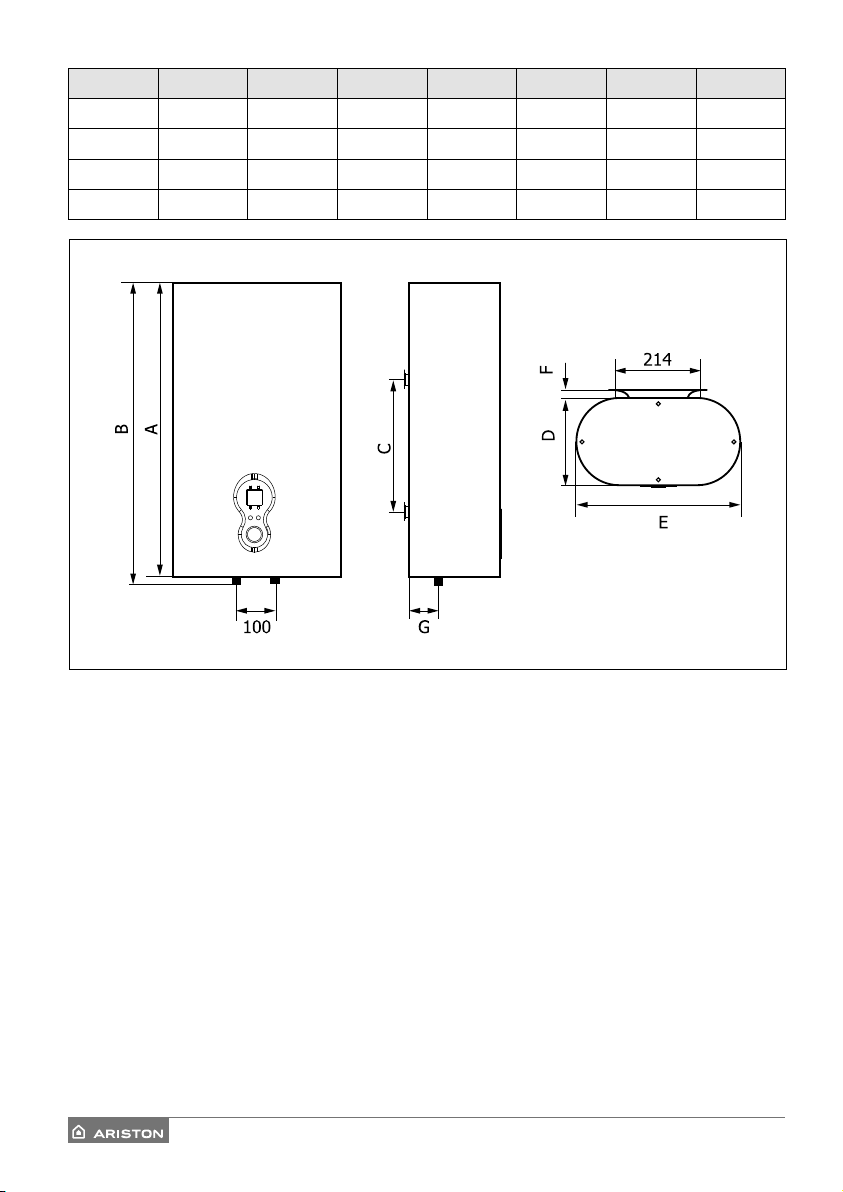
Capacity A B C D E F G
30 588 563 245 230 433 20 69
50 873 848 450 230 433 20 69
80 982 957 500 263 493 20 85
100 1202 1177 650 263 493 20 85
6 / EN
Page 7

Installation Method
dist ance
Note: the product must be installed by qualified personnel.
A. Drill two holes of 100mm in depth on the solid wall in horizontal/vertical direction by percussion drill
based on the exact model(b).
B. Insert the expansion bolt into the holes, then screw tightly the hook and let it upward (Figure A)
C. Put the hand rack which is on the upper of electric water heater,on the hook of expansion bolt cor-
rectly and tightly.
D. All the tubes are G1/2’, Connect properly the quipped water mixing valve,
One-way release valve,three-way inlet tube and three-way outlet tube according to dierent models
E. While in the case of little space,the electric water heater can be installed in the places where are
weather resistant,but in order to protect the thermal loss of the pipeline,the installation location
should be as close as possible to the water using location
F. Before use,you should completely check and verify the unit current is matching with the power sup-
ply and the wire capacity etc
Warning: you should check the wall which is to be installed the electric water heater onto is solid and
can undertake the weight of full capacity,the expansion bolts are prohibited installed in the joint part.
Figure A Figure B
7 / EN
Page 8

INSTALLING NORMS (for the installer)
This product is a device that must be installed vertically in order to operate correctly. Once installation is complete, and before any water is added or the power supply is connected, use a measuring
instrument (i.e. a spirit level) to check that the device has been installed perfectly vertical.
The appliance heats water to a temperature below boiling point. It must be linked up to a mains water
supply according to the appliance performance levels and capacity.
Before connecting the appliance, it is first necessary to:
- Check whether the characteristics (please refer to the data plate) meet the customer’s requirements.
- Make sure the installation conforms to the IP degree (of protection against the penetration of liquids)
of the appliance according to the applicable norms in force.
- Read the instructions provided on the packaging label and on the appliance data plate.
This appliance was designed to be installed only inside buildings in compliance with the applicable
norms in force. Furthermore, installers are requested to keep to the following advice in the presence of:
- Humidity: do not install the appliance in closed (unventilated) and damp rooms.
- Frost: do not install the appliance in areas where the temperature may drop critically and there may be
a risk that ice may form.
- Sunlight: do not expose the appliance to direct sun rays, even in the presence of windows.
- Dust/vapours/gas: do not install the appliance in the presence of particularly dangerous substances
such as acidic vapours, dust or those saturated with gas.
- Electrical discharges: do not install the appliance directly on electrical supplies that aren’t protected
against sudden voltage jumps.
In the case of walls made of bricks or perforated blocks, partition walls featuring limited static, or ma-
I
sonry dierent in some way from those stated, you first need to carry out a preliminary static check of
the supporting system. The wall-mounting fastening hooks must be designed to support a weight that is
three times higher than the weight of the water heater filled with water.
Fastening hooks with a diameter of at least 12 mm are recommended.
We recommend installing the appliance as close as possible to the delivery points to minimise heat loss
along the pipes. Local regulations may provide for restrictions on installation in bathrooms; observe any
regulatory minimum distances. To facilitate maintenance, make sure there is a clearance of at least 50
cm inside the enclosure for access to the electrical equipment.
Hydraulic connection
Connect the water heater’s inlet and outlet with pipes or fittings that are able to withstand temperature
in excees of 90°C at a pressure exceeding that of the working pressure. Therefore, we advise against
the use of any materials which cannot resist such high temperatures.
The appliance must not be supplied with water of hardness less than 12°F, nor with especially hard water
(greater than 25°F); we recommend installing a water softener, properly calibrated and controlled - do
not allow the residual hardness to fall below 15°F.
Screw a “T” piece union to the water inlet pipe with the blue collar. On one side of the “T” piece union,
screw a tap for draining the appliance that can only be opened with the use of a tool.
On the other side of the “T” piece union screw the safety valve supplied.
8 / EN
Page 9

Electrical connection
It is mandatory, before installing the appliance, to perform an accurate control of the electrical system by
verifying compliance with current safety standards, which is adequate for the maximum power absorbed
by the water heater (refer to the data plate) and that the section of the cables for the electrical connection is suitable and complies with local regulations.
The manufacturer is not liable for damage caused by lack of grounding or anomalous power supply.
Before starting up the appliance, check that the power rating matches that given on the nameplate.
The use of multiplugs, extensions or adaptors is strictly prohibited.
It is strictly forbidden to use the piping from the plumbing, heating and gas systems for the appliance
earthing connection. If the appliance is supplied with a power supply cable, should the latter need replacing, use a cable featuring the same characteristics must be routed into the hole in the back of the
appliance and connected to the thermostat terminals block.
Use a two-pole switch conforming with national laws in force (contact gap of at least 3 mm, preferably
equipped with fuses) to disconnect the appliance’s power supply.
The appliance must be grounded with a cable yellow/green and longer than the phase cable) connected
to the terminals marked . Before starting up the appliance, check that the power rating matches that
given on the nameplate.
Startup and commissioning
Before powering up the appliance, fill the heater with mains water.
To do so, open the mains cock and the hot water tap until all the air has been vented from the boiler.
Check for water leaks from the flanges, from the by-pass pipe, tighten down the bolts not too much, if
necessary and/or the rings.
Power the appliance by actuating the switch.
The appliances are EAC certified and compliant according to the associated relevant Regulations:
- TP TC 004/2011 “Technical regulations of the Customs Union on safety of low voltage equipment”
- TP TC 020/2011 “Technical regulations of the Customs Union on electro-magnetic compatibility”
9 / EN
Page 10

MAINTENANCE REGULATIONS (for qualified personnel)
All maintenance operations and service visits should be performed by a competent person (who
have the skills required by the applicable norms in force).
Before calling your Technical Servicing Centre, check that the fault is not due to lack of water or power
failure.
WARNING: disconnect the appliance from the mains before conducting any maintenance work.
Emptying the appliance
The appliance must be emptied if it is to be left unused for a long period and/or in premises subject to
frost.
To drain the appliance, proceed as follows:
- disconnect the appliance from the electricity mains;
- close the cut-o valve, if installed, or the main household water valve, if not;
- turn on the hot water tap (wash basin or bathtub);
- open the drain valve.
Replacing parts (when necessary)
Remove the plastic housing to access the electrical equipment.
The product is equipped with two dry heating elements (not in direct contact with the water) which,
therefore, can be replaced without emptying the appliance.
To replace a malfunctioning heating element disconnect the cable. Remove the damaged heating element and replace it. To access the anodes, first empty out the appliance.
Undo the bolts and remove the flanges. Replace the flange gasket every time you reassemble the
flange.
CAUTION!
Use only original parts from authorized service centres authorized by the manufacturer.
Periodical maintenance
The heating element should be descaled every two years to ensure it works properly (the frequency
must be increased, if water is very hard).
If you pre- fer not to use special liquids for this operation, simply crumble away the lime deposit without
damaging the heating element.
The magnesium anodes must be replaced every two years (this does not apply to appliances with stainless steel boilers); however, the anode should be checked every year if the water is corrosive or chloride
rich. To replace them, remove the heating elements and unscrew them from the brackets.
After routine or extraordinary maintenance, - recommend filling its tank with water and draining it completely so as to remove any residual impurities. Use only original spare parts supplied by the manufacturer’s authorised service centres.
Safety valve
Regularly check that the overpressure device is not jammed or damaged; if it is, remove any scale or
replace it. If the device has a lever or knob, operate it to:
- Drain the appliance, if necessary
- Check its operation from time to time.
10 / EN
Page 11

USEFUL INFORMATION
Before you clean the unit, make sure you have turned it o by setting its external switch to OFF.
Do not use insecticides, solvents or aggressive detergents: these can damage the unit’s painted and
plastic parts.
If the water comes out cold
Disconnect the appliance from the power supply and have the following checked:
- the presence of voltage on the power terminal block
- the circuit board;
- the heating element
If the water comes out boiling hot (steam in the taps)
Disconnect the appliance from the electricity supply and have the following checked:
- the circuit board
- the amount of scale on the boiler and components;
- the sensor
The hot water delivery is insucient
Disconnect the appliance from the electricity supply and have the following checked:
- the pressure of the water mains;
- the condition of the deflector on the cold water intake pipe;
- the condition of the hot water pipe;
- the electrical components
Water trickling from the pressure safety device
During the healing phase, some water may trickle from the tap. This is normal. To prevent the water
trickling, a suitable expansion vessel must be installed on the flow system. If the trickling continues even
after the healing phase, have the following checked:
- device calibration;
- the pressure of the water mains.
Caution: Never obstruct the appliance outletl
IF THE PROBLEM PERSISTS,NEVER ATTEMPT TO REPAIR THE APPLIANCE YOURSELF - ALWAYS
HAVE THIS DONE BY A QUALIFIED TECHNICIAN.
The indicated data and specifications are not binding; the manufacturer reserves the right to modify
them at his own discretion notification or replacement.
11 / EN
Page 12

ОБЩИЕ ТРЕБОВАНИЯ
1. Внимательно изучите данную инструкцию. В руководстве содержится
необходимая информация о мерах безопасности при установке,
эксплуатации и обслуживании водонагревателя.
2. Эксплуатация неправильно установленного прибора может привести
к травмам и повреждению имущества. Производитель не несет
ответственности за повреждения, полученные в результате неправильного
монтажа оборудования.
3. Все работы по монтажу и техническому обслуживанию должен выполнять
квалифицированный специалист в соответствии с действующими
нормами и правилами, а также с требованиями фирмы-изготовителя, с
использованием запасных частей, произведенных фирмой-изготовителем.
При несоблюдении данного требования производитель снимает с себя все
гарантийные обязательства
4. Храните упаковочные материалы (зажимы, полиэтиленовые пакеты,
пенополистирол и т.д.) в недоступном для детей месте. Упаковочный
материал вреден для здоровья.
5. Прибор не предназначен для использования лицами (включая детей)
с пониженными физическими, чувственными или умственными
способностями или при отсутствии у них жизненного опыта или знаний,
если они не находятся под контролем или не проинструктированы об
использовании прибора лицом, ответственным за их безопасность.
6. Не касайтесь прибора, если Вы без обуви или у Вас мокрые руки и/или ноги
7. Перед использованием прибора, после внепланового или очередного
технического обслуживания, мы рекомендуем заполнить бак устройства
водой, а затем полностью слить, чтобы удалить остаточные загрязнения.
8. Замена шнура питания производится только работниками авторизованных
сервисных центров.
9. Установка предохранительного клапана, входящего в комплект поставки,
является обязательным требованием. Запрещается устанавливать любую
запорную арматуру между предохранительным клапаном и входом в бак,
а также блокировать сливное отверстие предохранительного клапана.
Использование водонагревателя при давлении воды в водопроводной сети
свыше 5 бар, без установки редуктора давления воды ведет к досрочному
прекращению гарантийного срока.
10. Строго запрещается модифицировать или заменять предохранительный
12 / RUS
Page 13

клапан на другой, не соответствующий действующим требованиям и
нормам, если он не включен в комплект. Регулярно проверяйте, чтобы
предохранительный клапан (устройство защиты от избыточного давления)
не был заблокирован или поврежден. При необходимости замените его или
удалите известковый налет.
11. В режиме нагрева из дренажного отверстия предохранительного клапана
возможно появление капель воды. Это является естественным процессом,
связанным с тепловым расширением воды в процессе нагрева
12. Необходимо слить воду из водонагревателя, если в месте установки прибора
существует вероятность снижения температуры ниже 0°С.
13. Горячая вода свыше 50°С может вызвать сильные ожоги, вплоть до
смертельного исхода. Дети, пожилые люди и люди с ослабленным здоровьем
наиболее подвержены риску ожога.
14. Не храните легковоспламеняющиеся вещества в непосредственной близости
от оборудования.
15. Из водонагревателя может капать вода, поэтому не оставляйте под ним
ценные вещи и предметы.
16. Если установка электрического водонагревателя повлечет за собой
переоборудование (переустройство) жилых и нежилых помещений в жилых
домах, то допускается производить его установку только после получения
соответствующих разрешений в установленном порядке.
17. Транспортировать водонагреватель необходимо в вертикальном или
горизонтальном положении (в зависимости от модели) любым видом
крытого транспорта, надежно закрепив его, чтобы исключить возможные
удары, перемещения и падения внутри транспортного средства
18. Запрещается подвергать водонагреватель ударным нагрузкам при
погрузочно-разгрузочных работах.
19. При необходимости захвата упаковки зажимами при транспортировке
рекомендуется осуществлять захват сбоковых сторон упаковки.
20. В складских помещениях, где хранятся изделия, должна обеспечиваться
температура воздуха от +5°С до +40°С и относительная влажность воздуха
не более 80% при температуре +25°С.
21. И зделие должно храниться в упаковке в складских помещениях, защищающих
от воздействия атмосферных осадков, при отсутствии в воздухе паров
кислот, щелочей и других примесей
13 / RUS
Page 14

Уважаемый клиент,
Поздравляем Вас с приобретением электрического водонагревателя, произведенного
компанией «Аристон Термо Групп».
Мы убеждены, что данный водонагреватель полностью удовлетворит Ваши потребности. Наш
продукт - это результат многолетнего опыта в области высоких технологий. Мы гарантируем
качество продукции ARISTON, которому доверяют семьи во всем мире.
Мы просим Вас внимательно прочитать данную инструкцию для обеспечения корректной
установки и эксплуатации водонагревателя, а также настоятельно рекомендуем сохранить
руководство для быстрого доступа к дополнительной информации по обслуживанию.
ОСНОВНЫЕ ЭЛЕМЕНТЫ
A. Ручка управления
B1. Выход горячей воды
B2. Вход холодной воды
C. Дисплей
Комплект поставки
- Электрический водонагреватель, 1;
- Инструкция по эксплуатации, 1;
- Предохранительный клапан , 1;
- Крепежные элементы
30/50 L - 2 шт.
80/100 L - 4 шт.
- Гибкая подводка
C
A
B1 B2
Преимущества водонагревателя Ariston :
1) Внутренний бак из нержавеющей стали, устойчивый к коррозии, обеспечивает повышенную
прочность и ударостойкость.
2) Высокоэффективный нагревательный элемент
3) Устройство защиты от перегрева и избыточного давления
4) Увеличенный магниевый анод, для защиты от коррозии
5) Регулировка температуры
6) Стильный дисплей для управления настройками
14 / RUS
Page 15

технические характеристики
Модель
Номинальное
напряжение (В)
Номинальная
мощность (W )
Номинальное
давление (Бар)
Вес нетто (кг)
Габаритные
размеры (мм)
Монтаж
30л 230V/50Hz 800W+1200W 5 бар 11 563x433x230 Вертикальный
50л 230V/50Hz 800W+1200W 5 бар 14 848x433x230 Вертикальный
80л 230V/50Hz 800W+1200W 5 бар 20 957x493x263 Вертикальный
100л 230V/50Hz 800W+1200W 5 бар 24 1177x493x263 Вертикальный
Электрическая схема
ELCB
8.7A 23 0V~
кнопка
индикатор
L : ФАЗА
N : НЕЙТРАЛЬНЫЙ
тестирования
Кнопка сброса
тепловой выключатель
Главный
контроллер
Датчик температуры
Нагревательный элемент
Нагревательный элемент
оператор
Включение и работа
Ввод в работу
1. Для того чтобы включить прибор нажмите на центральную кнопку,
тем самым вы активируете режим нагрева. В режиме нагрева (не в
состоянии ожидания) водонагреватель готов к мгновенному нагреву.
HEATING
SAVE
Для того чтобы отключить прибор, нажмите на центральную кнопку.
2. Для установки температуры, вращайте ручку на 360 градусов по
часовой стрелке.
3. При нажатии кнопки I один раз загорится индикатор
означает, что водонагреватель работает в режиме мощностью 1200 Вт.
При нажатии кнопки II один раз загорится индикатор,
1.2KW
2.0K W
это
это
1.2KW
I II
2.0KW
означает, что водонагреватель работает в режиме мощностью 2000 Вт.
4. При нагревании загорается индикатор “
пока значение температуры не достигнет заданного. При достижении
заданной температуры индикатор “
индикатор “
SAV E
” .
HE ATING
” он будет включен
HE ATING
” будет выключен, загорится
15 / RUS
Page 16

Модель A B C D E F G
30л
50л
80л
100л
588 563 245 230 433 20
873 848 450 230 433 20
982 957 500 263 493 20
1202 1177 650 263 493 20
69
69
85
85
16 / RUS
Page 17

Монтаж
расстояние
водонагреватель
Предохранительный
клапан
Ручка
Воздухонепроницаемая шайба
Водоразборное
устройство
Подключение
к источникам
водоразбора
Вход холодной воды
горячая
вода
холодная
вода
Внимание! Монтаж и настройку водонагревателя должен выполнять квалифицированный специалист в
соответствии с действующими правилами и санитарно-гигиеническими нормами, а так же требованиями,
содержащимися в данном руководстве.
• Просверлите два отверстия глубиной 100 мм в капитальной стене. Установите в отверстия дюбеля,
вкрутите в них крепежный элемент и туго затяните. Установите водонагреватель на крюки при помощи
монтажной планки Все трубы имеют диаметр 1/2 “.
• Для сокращения теплопотерь, прибор следует установить на минимальном расстоянии от
водоразборного узла.
• Убедитесь, что параметры источника электропитания соответствуют техническим характеристикам
водонагревателя.
Установка водонагревателя производится на капитальной стене, способной выдержать вес
электроприбора в заполненном состоянии.
Рисунок A Рисунок B
17 / RUS
Page 18

УСТАНОВКА
Прибор должен быть установлен вертикально.
Данный прибор разработан для установки внутри зданий и предназначен для нагрева воды ниже точки
кипения, с возможностью снабжения горячей водой и дальнейшего поддержания заданной температуры.
Время нагрева воды зависит от объема водонагревателя и мощности нагревательного элемента.
Перед началом работы:
Проверьте, что параметры источника электропитания соответствуют техническим характеристикам
водонагревателя, указанным на идентификационной табличке.
- Убедитесь, что место установки прибора соответствует классу IP (степень защиты оболочки).
- Данный прибор разработан для установки внутри зданий, в бытовых и хозяйственных помещениях.
Запрещается.
- Устанавливать прибор в непроветриваемых и сырых помещениях.
- Эксплуатировать водонагреватель при отрицательных температурах..
- Подвергать прибор воздействию прямых солнечных лучей
- Устанавливать прибор в помещениях с концентрацией особо опасных газов или паров в воздухе.
- Устанавливать прибор в системе электроснабжения, не защищенной от внезапных скачков напряжения.
Установка водонагревателя производится на капитальной стене, с помощью кронштейна и крюков.
Рекомендуется использовать крюки с диаметром не менее 12 мм, крепление должно выдерживать
троекратный вес наполненного водой прибора. Рекомендуется устанавливать водонагреватель как
можно ближе к точке водоразбора, чтобы минимизировать потери тепла при прохождении по трубам.
Для облегчения технического обслуживания убедитесь, что под водонагревателем есть минимум 50 см
I
свободного пространства для доступа к оборудованию.
Гидравлическое соединение
Присоедините входной патрубок предохранительного клапана к магистрали холодной воды с помощью
трубы или гибкого шланга. Подсоедините к выходу горячей воды из водонагревателя трубу или
гибкий шланг для отвода горячей воды к месту водоразбора. Используйте материалы которые могут
выдерживать температуру свыше 90°С. При давлении превышающем рабочее установите редуктор перед
предохранительным клапаном.
Устройство не рассчитано на работу с водой, жесткостью менее 12°F. При воде с жесткостью выше 25°F, для
уменьшения образования накипи и вероятности выхода из строя нагревательного элемента, необходимо
использовать умягчитель. При этом жесткость воды не должна опускаться ниже 15°F.
Предохранительный клапан (A рис. 2), входящий в комплект поставки, необходимо установить на
входе холодной воды в водонагреватель (помечен синим кольцом). Для удобства обслуживания
рекомендуется установить тройник с запорным краном между входом холодной воды в водонагреватель
и предохранительным клапаном. Это позволит слить воду из водонагревателя, не демонтируя
предохранительный клапан. Для облегчения доступа воздуха в бак при сливе воды рекомендуется
установить тройник с запорным краном на выходе горячей воды из водонагревателя.
18 / RUS
Page 19

Электрическое подключение
Внимание! Фирма-изготовитель не несет ответственности за повреждения прибора вследствие
неправильного заземления или неправильных параметров источника электропитания. Убедитесь, что
параметры источника электропитания соответствуют техническим характеристикам водонагревателя,
указанным в табличке “Технические характеристики”.
Использование штекеров, удлинителей или адаптеров строго запрещено.
Категорически запрещается использовать трубопроводы из водопроводной, отопительной и газовой
систем для заземления прибора. При необходимости замены кабеля электропитания, используйте кабель
с такими же характеристиками.
Используйте автоматический выключатель в соответствии с действующим законодательством для
отключения электропитания
Провод заземления (желто-зеленого цвета) следует подсоединить к клемме, обозначенной символом .
Закрепите кабель электропитания с помощью кабельных зажимов.
Перед запуском прибора убедитесь, что номинальная мощность соответствует данным, указанным в
таблице “Технические характеристики”.
Включение и ввод в эксплуатацию
Перекройте подачу горячей воды системы центрального водоснабжения.Перед подключением
водонагревателя к источнику электропитания обязательно заполните бак водой. Для этого откройте
кран горячей воды на смесителе, потом кран подачи холодной воды в водонагреватель. Как только
водонагреватель наполнится, из смесителя потечет вода. Проверьте фланец и соединительную трубку на
наличие протечек. При необходимости отцентрируйте и подтяните гайки на фланце и соединительной
трубке. Закройте кран горячей воды на смесителе. Включите прибор в источник электропитания.
Настоящее изделие соответствует международной сертификации EAC и изготовлено в соответствии со
следующими техническими регламентами:
- TP TC 004/2011 Технический регламент Таможенного союза “О безопасности низковольтного оборудования”
- TP TC 020/2011 Технический регламент Таможенного союза “Электромагнитная совместимость технических
средств”
19 / RUS
Page 20

ТЕХНИЧЕСКОЕ ОБСЛУЖИВАНИЕ И РЕМОНТ
Внимание! Не пытайтесь ремонтировать прибор самостоятельно. Все работы по техническому
обслуживанию и ремонту должен выполнять квалифицированный специалист с соблюдением
правил техники безопасности, а так же требованиями, содержащимися в данном руководстве.
Прежде, чем обратиться в сервисный центр, убедитесь, что неисправность не связана с перебоями
водоснабжения или электропитания
ВНИМАНИЕ: Перед проведением любой операции по ремонту или обслуживанию отключите
прибор от электрической сети.
Слив воды
Необходимо слить воду из водонагревателя, если в месте установки прибора существует вероятность
снижения температуры ниже 0°С. Для слива воды выполните следующие действия :
- отключите электропитание прибора
- убедитесь, что вода внутри прибора имеет безопасную температуру
- перекройте подачу холодной воды в водонагреватель
- откройте кран горячей воды на смесителе для сброса давления внутри бака
- откройте сливной клапан
- после слива убедитесь в отсутствии воды внутри водонагревателя
Замена деталей (при необходимости)
Перед началом работ отключите прибор от источника электропитания и слейте воду из водонагревателя.
Снимите пластиковый корпус для доступа к электрооборудованию. Для замены неисправного
нагревательного элемента отсоедините клеммы от нагревательного элемента, отключите клемму
заземления, извлеките поврежденный нагревательный элемент и замените его. Обязательно используйте
новую прокладку каждый раз, когда меняете нагревательный элемент.
ВНИМАНИЕ!
Применяйте запасные части, выпускаемые только заводом-изготовителем
Рекомендуется регулярно осматривать и при необходимости удалять накипь с поверхности
нагревательного элемента с помощью средства для удаления накипи. Гарантия на нагревательный элемент
не действительна при выполнении одного или нескольких условий:
- жесткость воды превышает 25°F;
- толщина слоя накипи на поверхности ТЭНа составляет более 5 мм;
- остаточный размер магниевого анода составляет менее 30% от первоначального
Магниевый анод является неотъемлемой составной частью системы защиты водосодержащей емкости и
нагревательного элемента (ТЭНа) от коррозии. Необходимо ЕЖЕГОДНО проверять состояние магниевого
анода. При сильном изнашивании магниевый анод необходимо заменить. Необходимо производить замену
магниевого анода не реже 1 раза в 24 месяца (за исключением водонагревателей с водосодержащей
емкостью из нержавеющей стали).
Предохранительный клапан
Регулярно проверяйте, чтобы предохранительный клапан (устройство защиты от избыточного давления)
не был заблокирован или поврежден. При необходимости замените его или удалите известковый налет.
Если предохранительный клапан оснащен рычагом, поднятие последнего можно использовать для
регулярной проверки исправной работы клапана.
20 / RUS
Page 21

ПОЛЕЗНАЯ ИНФОРМАЦИЯ
Перед чисткой устройства убедитесь, что вы выключили его, установив его внешний выключатель в
положение OFF. Не используйте инсектициды, растворители или агрессивные
моющие средства: они могут повредить окрашенные и пластиковые детали устройства.
Если вода выходит холодной,
отключите прибор от источника питания и проверьте следующее :
- наличие напряжения на клеммной колодке питания
- исправность работы печатной платы
- исправность работы нагревательного элемента
Если вода подается кипящей,
отключите прибор от источника питания и проверьте следующее:
- исправность работы печатной платы
- Количество накипи в баке нагревателя
- Исправность термостата
Если проток горячей воды недостаточный,
отключите прибор от источника питания и проверьте следующее :
- давление воды в водопроводе
- состояние дефлектора на патрубке выхода холодной воды
- состояние труб горячей воды
- электрические компоненты
Течет вода из предохранительного клапана
В режиме нагрева из дренажного отверстия предохранительного клапана возможно появление воды.
Это является естественным процессом, связанным с тепловым расширением воды в процессе нагрева.
Для устранения течи рекомендуется установка расширительного бака подходящего объема в систему.
Если после этих действий вода продолжает течь, проверьте следующее :
- настройку прибора
- давление в водопроводе
Перед проведением любой операции по ремонту или обслуживанию отключите прибор от электрической
сети.
НЕ ПЫТАЙТЕСЬ РЕМОНТИРОВАТЬ ПРИБОР САМОСТОЯТЕЛЬНО. ВСЕ РАБОТЫ ПО ТЕХНИЧЕСКОМУ
ОБСЛУЖИВАНИЮ И РЕМОНТУ ДОЛЖЕН ВЫПОЛНЯТЬ КВАЛИФИЦИРОВАННЫЙ СПЕЦИАЛИСТ.
Производитель оставляет за собой право вносить любые незначительные изменения в
конструкцию, дизайн, комплектацию и иные характеристики изделия без предварительного
уведомления.
21 / RUS
Page 22

ГАРАНТИИНЫЙ ТАЛОН
ЭЛЕКТРИЧЕСКИЕ ВОДОНАГРЕВАТЕЛИ
Просим Вас хранить талон в течение всего гарантийного срока. При покупке изделия требуйте
заполнения гарантийного талона. Просим Вас осмотреть водонагреватель и проверить комплектность
до заполнения гарантийного талона. Претензии по механическим повреждениям внешней поверхности
и некомплектности изделия после продажи не принимаются. Для гарантийного ремонта предъявляйте
отрывной талон вместе с чеком, где указана дата покупки. Без предъявления данного талона, его
неправильном заполнении или при отсутствии печати торгующей организации претензии к качеству
не принимаются и ремонт не производится.
Модель _ _ _ _ _ _ _ _ _ _ _ _ _ _ _ _ _ _ _ _ _ _ _ _ _ _ _ _ _ _ _ _ _ _ _ _ _ _ _ _ _ _ _ _ _ _ _ _ _ _ _ _ _ _ _ _ _ _ _ _ _ _ _ _ _ _ _ _ _ _ _ _ _ _ _ _ _ _ _ _ _ _
Код модели _ _ _ _ _ _ _ _ _ _ _ _ _ _ _ _ _ _ _ _ _ _ _ _ _ _ _ _ _ _ _ _ _ _ _ _ _ _ _ _ _ _ _ _ _ _ _ _ _ _ _ _ _ _ _ _ _ _ _ _ _ _ _ _ _ _ _ _ _ _ _ _ _ _ _ _ _ _ _ _
Серийный номер _ _ _ _ _ _ _ _ _ _ _ _ _ _ _ _ _ _ _ _ _ _ _ _ _ _ _ _ _ _ _ _ _ _ _ _ _ _ _ _ _ _ _ _ _ _ _ _ _ _ _ _ _ _ _ _ _ _ _ _ _ _ _ _ _ _ _ _ _ _ _ _
(наименование, место нахождение и печать предприятия-продавца)
_ _ _ _ _ _ _ _ _ _ _ _ _ _ _ _ _ _ _ _ _ _ _ _ _ _ _ _ _ _ _ _ _ _ _ _ _ _ _ _ _ _ _ _ _ _ _ _ _ _ _ _ _ _ _ _ _ _ _ _ _ _ _ _ _ _ _ _ _ _ _ _ _ _ _ _ _ _ _ _ _ _ _ _ _ _ _ _ _ _ _ _
Торгующая организация _ _ _ _ _ _ _ _ _ _ _ _ _ _ _ _ _ _ _ _ _ _ _ _ _ _ _ _ _ _ _ _ _ _ _ _ _ _ _ _ _ _ _ _ _ _ _ _ _ _ _ _ _ _ _ _ _ _ _ _ _ _ _ _ _
(ФИО, подпись продавца)
Дата продажи « _ _ _ _ _ _ _ _ _ _ _ _ _ _ _ » _ _ _ _ _ _ _ __ _ _ _ _ _ _ _ _ _ _ _ _ _ _ _ _ _ _ _ _ _ _ _ _ _ _ _ _ _ _ _ _ _20 _ _ _ _ _ _ _ _ _года
С условиями гарантии согласен_ _ _ _ _ _ _ _ _ _ _ _ _ _ _ _ _ _ _ _ _ _ _ _ _ _ _ _ _ _ _ _ _ _ _ _ _ _ _ _ _ _ _ _ _ _ _ _ _ _ _ _ _ _ _ _ _ _ _
1. Гарантийный срок
Гарантийный срок на все водонагреватели - 1 год.
На перечисленные ниже составные части отдельных серий:
Сталь с эмалевым покрытием
- Водосодержащая емкость серий LEXIS 50, LEXIS 80, LEXIS 100 - 5 лет;
- Водосодержащая емкость серий JOVIS 50, JOVIS 80, JOVIS 100- 5 лет;
2. Условия гарантийного обслуживания
Данный гарантийный талон при соблюдении предусмотренных условий дает право на бесплатный
гарантийный ремонт водонагревателя и его составных частей. Гарантийный ремонт осуществляется
по месту установки водонагревателя силами авторизованного сервисного центра, информация
о котором находится в приложении к данному талону. При ее отсутствии или недостоверности,
а так же нарушении сервисным центром условий гарантии, Вы можете обратиться в торговую
организацию или в представительство компании-производителя.
Указанные в п. 1 гарантийные сроки исчисляются со дня продажи изделия. Дата продажи изделия
указывается в гарантийном талоне и чеке покупки. При отсутствии в талоне или чеке даты продажи,
гарантийный срок исчисляется с момента изготовления изделия.
Дата изготовления и технические характеристики водонагревателя указаны на идентификационной
табличке, размещенной на корпусе изделия. Гарантийные сроки в отношении водонагревателей
и их составных частей, переданных потребителю взамен водонагревателей и их составных частей
ненадлежащего качества, истекают в последний день гарантийного срока, установленного на
замененный водонагреватель или составную часть.
Магниевый анод является расходным материалом и не подлежит замене по гарантии.
(ФИО, подпись продавца)
22 / RUS
Page 23

3. Срок службы изделия
При соблюдении правил установки, эксплуатации и технического обслуживания срок службы
составляет не менее 3 лет.
На перечисленные ниже отдельные серии срок службы составляет:
- Водосодержащая емкость серий LEXIS 50, LEXIS 80, LEXIS 100 - 5 лет;
- Водосодержащая емкость серий JOVIS 50, JOVIS 80, JOVIS 100- 5 лет;
4. Досрочное прекращение гарантийного сроке
Гарантийный срок прекращается до истечения указанного в п.1 периода времени, при наличии
одного или нескольких обстоятельств:
- Нарушение потребителем правил установки, хранения, транспортировки и эксплуатации изделия;
- Магниевый анод не был заменен в период, превышающий 24 месяца;
- Самостоятельный ремонт и замена запасных частей, нарушающие работоспособность
изделия; - Самостоятельный демонтаж водонагревателя с места установки. Осмотр,
проверка качества и экспертиза вышедшего из строя водонагревателя производится
авторизованным сервисным центром производителя только по месту установки прибора;
- Нанесение изделию механических повреждений;
- Несоответствие параметров сетей электро- или водоснабжения существующим нормам и
стандартам;
- Использование изделия не по назначению;
- Отсутствие на корпусе изделия идентификационной таблички с серийным номером; Отсутствие перед предохранительным клапаном редуктора дла понижения давления при
давлении водопроводной сети выше 5 бар;
- Отсутствие непосредственно на входе в водонагреватель предохранительного клапана,
его повреждение или засорение.
5. Дополнительная информация
Для установки и регулярного сервисного обслуживания приобретенного оборудования
мы рекомендуем воспользоваться услугами наших сервисных центров. Через сеть наших
сервисных центров Вы можете приобрести запасные части и комплектующие изделия к
водонагревателю, а также получить необходимую техническую консультацию.
Перед установкой и использованием изделия внимательно изучите прилагающуюся
инструкцию
Импортер, уполномоченная организация:
ООО «Аристон Термо Русь», Россия, 188676, Ленинградская область, Всеволожский район,
г. Всеволожск, Промышленная зона производственная зона города Всеволожска, ул.
Индустриальная, д. № 9, корпус лит. А
Импортер, уполномоченная организация:
Представительство ООО «Аристон Термо Русь» (РФ) в Республике Беларусь, Беларусь, 220053,
г. Минск, ул. Мирная, д.37 Г, пом.5
Найдите ближайший к Вам сервисный центр:
www.ariston.com
service.ru@aristonthermo.com
+7 (495)-777-33-00
23 / RUS
Page 24

Viale Aristide Merloni 45 - 60044 Fabriano (AN) Italy
Ariston Thermo SpA
Telefono 0732 6011 - Fax 0732 602331
info.it@aristonthermo.com
www.aristonthermo.com
 Loading...