

Ariston TVM631EUHA, AS600VXFR, AS600VKW, AS600VEX, AS600VXAG Service Information
Information
Indesit Company UK Limited
© 2008 Reg. Office: Peterborough PE2 9JB. Registered in London: 106725
Service
6 kg
Vented
Electro
Mechanical
Tumble Dryers
Models Comm.
Covered Code
Hotpoint-Ariston
TVM631EUHA 48890
Ariston
AS600VXFR 49613
AS600VKW 51893
AS600VEX 51891
AS600VXAG 51896
5407394 Issue 1 May 2008

2
SAFETY NOTES & GENERAL SERVICING ADVICE
1. This manual is NOT intended as a comprehensive repair/maintenance guide to the appliance.
2. It should ONLY be used by suitably qualified persons having technical competence applicable
product knowledge and suitable tools and test equipment.
3. Servicing of electrical appliances must be undertaken with the appliance disconnected (unplugged)
from the electrical supply.
4. Servicing must be preceded by Earth Continuity and Insulation Resistance checks.
5. Personal safety precautions must be taken to protect against accidents caused by sharp edges on
metal and plastic parts.
6. After Servicing the appliance must be rechecked for Electrical Safety. In the case of appliances which
are connected to a water supply (i.e.: Washing Machines, Dishwashers & Food Centres etc.) checks
must be made for leaks from seals gaskets and pipe work and rectification carried out where
necessary.
7. It can be dangerous to attempt ‘DIY’ repairs / maintenance on complex equipment and the Company
recommends that any problem with the appliance is referred to its own Service Organisation.
8. Whilst the Company has endeavoured to ensure the accuracy of the data within this publication they
cannot hold themselves responsible for any inconvenience or loss occasioned by any error within.
SERIAL NUMBER / INDUSTRIAL CODE EXPLANATION
Serial Number Example
3 10 02 0895
Four remaining digits = Build number that day 895
th
built
Third two digits = Day of manufacture 2
nd
of month
Second two digits = Month of manufacture October
First digit = Year of manufacture 2003
Industrial Code Example
37 24455 0010
Last four digits = 0000 original production.
Second five digits = COMMERCIAL CODE*
First two digits = Factory of origin
* Vital for correct model information and system identification
Other numbers denote major production changes

3
INDEX
Safety Notes & General Servicing Advice . . . . . . . . . . . . . . . . . . . . . . . . . . . .2
Serial Number / Industrial Code Explanation. . . . . . . . . . . . . . . . . . . . . . . . . .2
Technical Specifications . . . . . . . . . . . . . . . . . . . . . . . . . . . . . . . . . . . . . . . . . .4
Machine Function . . . . . . . . . . . . . . . . . . . . . . . . . . . . . . . . . . . . . . . . . . . . . 5 - 6
Console . . . . . . . . . . . . . . . . . . . . . . . . . . . . . . . . . . . . . . . . . . . . . . . . . . . . . . . .7
Programmes . . . . . . . . . . . . . . . . . . . . . . . . . . . . . . . . . . . . . . . . . . . . . . . . . . . .8
Component Description. . . . . . . . . . . . . . . . . . . . . . . . . . . . . . . . . . . . . . . 9 - 12
Dismantling Instructions . . . . . . . . . . . . . . . . . . . . . . . . . . . . . . . . . . . . . 13 - 17
Timer Sequence Charts . . . . . . . . . . . . . . . . . . . . . . . . . . . . . . . . . . . . . . 18 - 19
Wiring Diagram - Models TVM631EUHA, AS600VEX, AS600VXFR
Invensys Timer. . . . . . . . . . . . . . . . . . . . . . . . . . . . . . . . . . . . . . . . . . . . . . .20
ELBI Timer . . . . . . . . . . . . . . . . . . . . . . . . . . . . . . . . . . . . . . . . . . . . . . . . . .21
Wiring Diagram - AS600VXAG, AS600VKW
Invensys Timer. . . . . . . . . . . . . . . . . . . . . . . . . . . . . . . . . . . . . . . . . . . . . . .22
ELBI Timer . . . . . . . . . . . . . . . . . . . . . . . . . . . . . . . . . . . . . . . . . . . . . . . . . .23

4
TECHNICAL SPECIFICATION
General All models Polar White
Features Reversing - Dual Heat - 140 minutes Programme Timer,
Easy Iron (crease removal) and Auto Drying options, 12 hour
Delay Timer and End of Programme Alarm (with Switch and
Start Switch).
Energy Efficiency C
Noise 69 dB
Country of Origin Great Britain
Dimensions
Height 850 mm
Width 595 mm
Depth 550 mm
Weight 35 kg (packed)
Drum Speed 55 rpm Reversing
Drying Load Dry Weight Maximum 6 kg
Drum Volume 100 litres
Door Operation Lever operated door catch
Heater High Heat - 2200W @ 230V
Low Heat - 1100W @ 230V
Heater Controls Heat Selection Push Button out for High Heat
Control Thermostats
Cycling Thermostat 120°C
One Shot 150°C
Eco Thermostats
Full Load 55°C White Spot
Half Load 60°C Purple Spot
All thermostats are rated at 10 amps @ 230 Volts
Timer Range up to 140 minutes including 7.5 minutes Cool Tumble.
Two Eco Programmes and Easy Iron (crease removal)
programme.
Motor - Type 358 Capacitor run, single phase, 2 Pole, induction type
Motor Speed 2800 rpm
Capacitor 7.5 uF

5
MACHINE FUNCTION
Cold air is drawn into the dryer cabinet interior thro ug h lo uvr es in the cabi ne t ba se, pa sse s throu gh
the large hole in the inner back panel adjac ent to th e fan a nd is driv en th rough the elemen t hous ing
on the inner back panel. After passing through the element windings and through holes in the drum
back plate into the drum interior, the now warm air is driven through the load to the front of the drum.
A webbing seal, fixed to the inside of the inner back panel, prevents warm air being driven into the
cabinet interior. As the drum revolves, the load is tumbled through the warm air stream, that extracts
moisture from the damp fabric. The now mo ist and coo led air passes through the filter in the air duct
on the back of the front panel, where any fluff picked up from the load is removed. The air then travels
through the front to rear air duct, leaving the dryer at the rear outlet.
If required, a vent hose may be attached to the outlet, to take exhaust air away from the dryer.
A cut-out on the element housing, cuts the electricity Live supply to the element, if the air temperature
in the housing becomes too high due to a restriction in the air flow, e.g a blocked filter. The cut-out
automatically resets when the air temperature drops to an acceptable level and cycles if the fault
persists.
A second 'one shot' cut-out, mounted alongside the 'auto reset' cut- out, is fitted as a safety device to
break the element Neutral connection, if the air temperature reaches an unsafe level due to failure of
the 'auto reset' cut-out.
There are two thermostats in the front air duct when only on e is in use at any one time de pending on
which programme is selected. These sense the exhaust temperature rise when the load becomes
dry and energise the timer motor on the main timer. This allows it to advance to cool run.
AIRFLOW DIAGRAM

6
AUTOMATIC DRYING - Fitted to some models only
To work correctly High Heat has to be enabled and between 3 kg to 6 kg of Cottons dried. If smaller
or delicate loads are dried using the automatic setting, erratic results will be achieved.
Automatic Drying Explanation
NOTE: - The heat switch must be set to the high p osition otherwise there will be no circuit to the timer
motor or heater when the exhaust thermostat signals tha t the clot he s are dry.
Sequence of Automatic Drying System
• First 20 minutes, full heat controlled by the timer. This is to pre -heat the clothes and drum before
the exhaust thermostats take control.
• The timer moves to its next cam position. The timer motor is now disconnected and the dryer
tumbles and heats.
• When the clothes are dry, the exhaust thermostat opens. This provides a Live supply to the timer
motor. The timer moves to the next cam position.
• 5 minutes of tumbling with the lower element only. The timer moves to the next cam position.
• Finally 7.5 minutes of tumble with no heat.
7
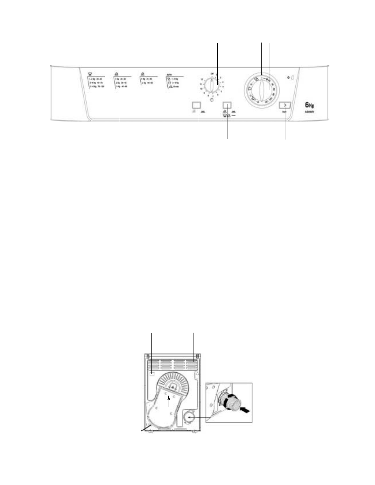
CONSOLE
NOTE: - Not all of the above functions and options are available on all models covered in this
manual.
The START button begins drying a selected
programme.
The HEAT button selects the drying
temperature.
OUT: Low Heat. IN: High Heat.
The ALARM buzzer signals the end of a
drying cycle.
OUT: Buzzer OFF. IN: Buzzer ON.
The ACTIVE indicator light signals that the
dryer is in use. This light will glow when the
START button is pressed. It will remain on
until the door is opened or the power is turned
off. this light will be on during a delayed start
programme.
The Drying Guide allows the customer to
consult a user friendly table of fabric types and
load capacities and shows a guide of the
programmes available.
The DELAY knob sets a delay on the dryers
start time, it can be rotated clockwise until you
reach the number of hours you want to delay
the start time. If you have gone too far, turn the
knob anti-clockwise.
The TIMER / PROGRAMMES knob sets the
drying time or programme. Rotate it clockwise,
never anti-clockwise, until the indicator is
pointing to the time or programme you want to
select.
p
Drying Guide
PROGRAMMES
Knob
TIMER
Knob
START
Button
Indicator
ACTIVE
Light
HEAT
Button
ALARM
Button
Air Intake Vent
Vent Tube fitted here
Caution: Hot!
Rating plate
 Loading...