


Instructions for use
Splendide
by
®
WASHING MACHINE
NA
English, 1
ARWXF 129 W
Contents
Important safety instructions 2-3
Important safety instructions
Grounding Instructions
Safety
Installation instructions 4-5-6
Unpacking and leveling
Minimum Installation Spacing
Connecting Water Inlet
Drainage
Connecting the drain hose
Electrical
Under Sink Method
Technical data
Description of the washing machine
and starting a wash cycle 7-8
Control panel
Indicator lights
Starting a wash cycle
Wash cycles 9
Table of wash cycles
Special wash cycles
NA
Personalisation 10-11
Setting the temperature
Setting the spin speed
Functions
Detergents and laundry 12
Detergent dispenser drawer
Bleach cycle
Preparing the laundry
Garments requiring special care
Load balancing system
Helpful Hints
Care and maintenance instructions 13
Cutting off the water and electricity supplies
Cleaning the washing machine
Cleaning the detergent dispenser drawer
Caring for the door and drum of your appliance
Cleaning the pump
Checking the water inlet hose
Troubleshooting 14
Service 15
Warranty, 16-17
1

Important safety instructions
NA
IMPORTANT SAFETY INSTRUCTIONS
WARNING - To reduce the risk of fire, electrical shock, or
injury to persons when using your appliance, follow basic
precautions, including the following:
• Read all instructions before using the appliance.
• Do not wash articles that have been previously cleaned
in, washed in, soaked in, or spotted with gasoline, dry
cleaning solvents, other flammable, or exlosive substances as they give off vapors that could ignite or explode.
• Do not allow children to play on or in the appliance. Close supervision of children is necessary when the appliance is used near children.
• Before the appliance is removed from service or discarded, remove the door to the washing compartment.
• Do not add gasoline, dry cleaning solvents, or other flammable or explosive substances to the wash water. These
substances give off vapors that could ignite or explode.
• Do not install or store this appliance where it will be
exposed to the weather.
• Do not tamper with controls.
• Under certain conditions Hydrogen gas may be produced in a hot water system that has not been used for 2
weeks or more. HYDROGEN GAS IS EXPLOSIVE. If the
hot water system has not been used for such a period,
before using the appliance, turn on all hot water faucets
and let the water flow from each for several minutes.
This will release any accumulated hydrogen gas. As the
gas is flammable do not smoke or use an open flame
during this time.
• Turn off water faucets to relieve pressure on hoses and
valves and to minimize leakage if a break or rupture
occurs.
• Do not reach into the appliance if the tub or drum is
moving.
• Do not repair or replace any part of the appliance or
attempt any servicing unless specifically recommended
in the user-maintenance instructions or in published
user-repair instructions that you understand and have
the skills to carry out.
• Good, safe practices and caution MUST be applied
when installing, operating, and maintaining any appliance. Follow basic precaution.
• Disconnect power to the washer at the circuit breaker
or fuse box, or unplug the machine in an emergency or
when servicing required. Have the installer show you and
label the proper switch or fuse at the electrical disconnect box.
• The interior of the appliance should be cleaned periodically by qualified service personnel.
• Before loading the washer, make sure the drum is empty.
SAVE THESE INSTRUCTIONS
GROUNDING INSTRUCTIONS
This appliance must be grounded. In the event of malfunction or breakdown, grounding will reduce the risk of
electric shock by providing a path of least resistence for
electric current. This appliance is equipped with a cord having an equipment-grounding conductor and a grounding
plug. The plug must be plugged into an appropriate outlet
that is properly installed and grounded in accordance with
all local codes and ordinances.
WARNING - Improper connection of the equipment-grounding conductor can result in a electric shock.
Check with a qualified electrician or service representative
or personnel if you are in doubt as to whether the appliance is properly gounded.
Do not modify the plug provided with the appliance: if it will
not fit outlet, have a proper outlet installed by a qualified
electrician.
2
Safety
!
!
C
U
L
US LISTED
®
!
CAUTION RISK
OF ELECTRIC
SHOCK DO
NOT OPEN
CAUTION:
To reduce the risk of electric shock, DO NOT remove cover (or back)/no user servicable parts inside.
Refer for servicing to qualified services personnel.
The model number of this product may be found on the back of the unit; the serial number of the label affixed inside the door
and to the back of the unit.
You should note the model and serial numbers of this unit in the space provided. Retain this booklet as a permanent record
of your purchase to aid in identification in the event of theft.
MODEL N.
SERIAL N.
WARNING:
TO PREVENT FIRE OR SHOCK HAZARD DO NOT EXPOSE THIS PRODUCT TO RAIN OR MOISTURE.
NA
The linghtning flash with arrowhead symbol, within an equilateral triagle, is intended to alert the user to the presen-
ce of uninsulated “dangerous voltage” within the product’s enclosure that may be of sufficient magnitude to constitu-
te a risk of electric shock to persons.
The exclamation point within an equilateral triangle is intended to alert the user to the presence of important opera-
ting and maintenance (servicing) instructions in the booklet.
Indesit Company offers to his customers products with the ENERGY STAR Label.
This appliance was tested by UL and conforms with both Canadian and U.S. UL safety requirements
and displays their Mark
3
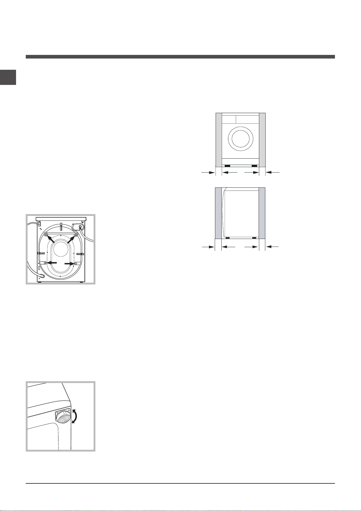
0" *
0" *
Recessed Front View
1" *
1"
Side View
Installation instructions
NA
! This instruction manual should be kept in a safe place
for future reference. If the washer is sold, transferred or
moved, make sure that the instruction manual remains with
the machine so that the new owner is able to familiarise
himself/herself with its operation and features.
! Read these instructions carefully: they contain vital infor-
mation relating to the safe installation and operation of the
appliance.
Unpacking and levelling
Unpacking
1. Remove the washer from its packaging.
2. Make sure that the washer has not been damaged
during the transportation process. If it has been damaged,
contact the retailer and do not proceed any further with the
installation process.
3. Remove the 4 protective
screws (used during transportation) and the rubber
washer with the corresponding spacer, located on the
rear part of the appliance
(see figure).
Levelling the machine correctly will provide it with stability,
help to avoid vibrations and excessive noise and prevent it
from shifting while it is operating.
Minimum Installation Spacing
This appliance may be installed in a recessed area, closet
or alcove. The installation spacing is in inches and is the
minimum acceptable.
4. Close off the holes using the plastic plugs provided.
5. Keep all the parts in a safe place: you will need them
again if the washer needs to be moved to another location.
! Packaging materials should not be used as toys for
children.
Levelling
1. Install the washer on a flat sturdy floor, without resting it
up against walls, furniture cabinets or anything else.
2. If the floor is not perfectly
level, compensate for any
unevenness by tightening
or loosening the adjustable
front feet (see figure); the an-
gle of inclination, measured
in relation to the worktop,
must not exceed 2°.
*Additional spacing should be considered for easy installation, servicing and compliance with local codes and
ordinances. Installations must conform with the minimum
dimensions indicated.
4
A & B = 25" (62 cm) min. / 34" (86 cm) max.
Floor Standpipe
Wall Standpipe
A
B
Fig. 4
25" (62 cm) min.
with an air break
Laundry Sink Drain
Fig. 5
Sink Drain W/ "Y" Branch Tailpiece
!
H
C
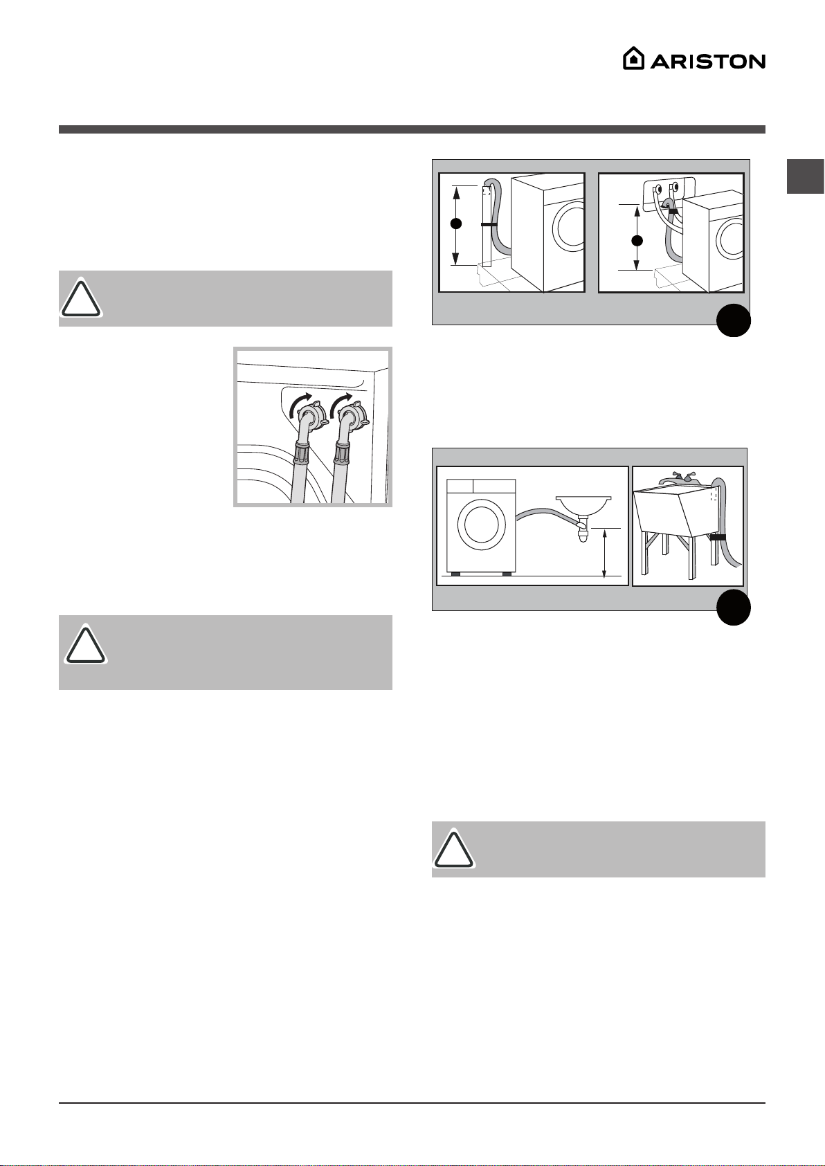
Connecting Water Inlet
!
!
If the water pipes you will be connecting to are new or
unused, run the water until clear to remove any debris that
could clog the water valve screens or valves before connecting the machine. NOTE: Supply shut-off valves should
be easily accessible.
NA
Important:
thin the values indicated on the “Technical Data”
chart.
1. Screw the cold water fill
hose (C blue connector) onto
the cold water supply until
tight.
2. turn on the cold water
supply and check for leaks,
tighten if necessary.
3. Screw the hot water fill
hose (H red connector) onto
the hot water supply until tight.
4. Turn on the hot water supply and check for leaks,
tighten if necessary.
Important:
mage to the couplings can result. The couplings
should be tightened by hand; a tool should only
be used if a leak occurs.
Drainage
• Standpipe Diameter/Capacity - Needs a 1 ¼”
minimum diameter standpipe with a minimum carry-away
capacity of 7 gallons per minute.
• Top of Standpipe - Must be between 25” - 34” high
from the bottom of the machine.
• Outlet End of Drain Hose (provided with the unit)
- Must be at least 20” above the bottom of the washer-
dryer. An air break must be available at the standpipe to
avoid siphoning. No more than 6” of the drain hose should
be inserted into the drain pipe to prevent siphoning.
Connecting the drain hose
It is possible for the water to be discharged into a sink,
standpipe or drainpipe, but an air break must be available
at a min. 20” height to prevent the machine from siphoning
(Fig. 6).
Water pressure MUST range wi-
Do not use excessive force. Da-
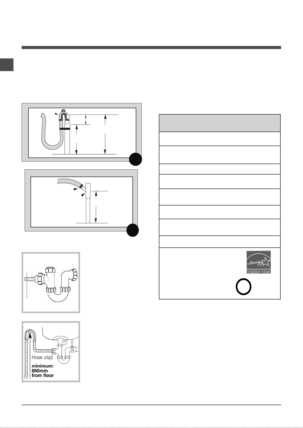
Standpipe Drain System - Installations require a minimum
1 ¼” (3.2 cm) diameter standpipe with a minimum carry
away capacity of 7 gallons (26 liters) per minute.
Wall or Floor Standpipe Drain System - The top of the
standpipe must be between 25” (62 cm) - 34” (86 cm)
from the bottom of the washer (Fig. 4).
Sink Drainpipe System
system must be above the trap (Fig. 5). When routing the
drain hose through cabinets or walls, use a protective material such as electrical or duct tape to cover sharp edges
that could damage the drain hose. Use a suitable clamp
to secure the drain hose to the “Y” branch or the disposer.
With a sink drainpipe system, you may connect directly:
1) to a disposer by following the manufacturers attachment
method.
2) directly to a “Y” branch tail piece (available at most
hardware stores).
Important:
not kinked and that water flow is not restricted.
3) Through the floor to a separate trap. The trap must be
vented to prevent siphoning. To provide proper venting,
install an Air Gap Kit (available at most hardware stores).
4) To the to the faucet using a Faucet Adapter Kit (available
separately).
• Use a U-Clamp (provided in your accessories packet)
or suitable item to secure the outlet end of the drain hose
(pre-installed on the back of your machine).
-
Entry into the sink drain
Make sure that the drain hose is
5
NA
C
U
L
US LISTED
®
20" (62 cm) min.
34" (86 cm) max.
Standpipe
"Y" Tail Piece
This connection MUST be
before drain trap and at
least 20" (50.8 cm) above
the floor where washer will
be installed.
Cable tie
Floor Standpipe w/ "Y" Branch Tail Piece
Fig. 7
20" (50 cm) min.
with an air break
25" (62 cm) min.
34" (86 cm) max.
6" max.
Standpipe
Floor Standpipe
Fig. 6
U-Clamp
• Insert the outlet end of the drain hose into the standpipe,
wall or floor drain (Fig. 6). NOTE: The outlet end of the
drain hose MUST be at least 20” (50 cm) above the base
of the machine. No more than 6” of the drain hose should
be inserted into the drain pipe to prevent siphoning.
• Use a strap, cable tie, or similar item to hold the hose or
the U-Clamp in place.
Electrical
• Machine Voltage/Amperage - 120V, 60 Hz, 4 Amp.
• Connection - 3-prong plug with 6’ cord is provided with
the machine.
• Circuit/Protector - 3-wire single phase, 120V, 60 Hz, AC,
on a separate 15 Amp circuit.
Technical Information
Technical data
Under Sink Method
1. Cut the blocked end of
the under sink drainage unit.
Model
Dimensions
Weight
Minimum Installa-
tion Clearances
Capacity
Electrical
connections
Water
connections
Max. Spin speed
Indesit Company offers to his customers
products with the ENERGY STAR Label.
This appliance was tested by UL and
conforms with both Canadian and U.S.
UL safety requirements and displays
their Mark.
ARWXF 129 W
width: 23.4”” (59.5 cm)
height: 33.24”” - 33.75”” (84.5 - 85.7 cm)
depth: 22”” (55.9) cm
148 lbs
Sides: 0””
Front / Back: 1””
Washing: 2 to 15 lbs. (1 to 7 kg)
Voltage: 120Volts, 4 A, 60 Hz
Max. Pressure: 0.69 MPa (6.9 bar), 100 psi
Min. Pressure: 0.05 MPa (0.5 bar), 7.2 psi
up to 1200 RPM
6
2. Fix the hooked end sup-
porta minimum of 620 mm
from the floor.
3. Use a hose clip clamp to
securely attach the grey drainage hose end to the under
sink drainage unit using a
hose. clamp

Description of the washing
machine and starting a wash cycle
Control panel
button with indicator
ON/OFF
light
Detergent dispenser drawer
WASH CYCLE
WASH CYCLE PROGRESS
DISPLAY
TEMPERATURE
button
SPIN SPEED
button
knob
CONTROL PANEL LOCK
button with indicator light
indicator lights
FUNCTION
buttons with
indicator lights
DOOR
LOCKED
indicator light
START/PAUSE
button with indicator
light
NA
WARNING: To reduce the risk of fire, electric shock, or
injury to persons, read the IMPORTANT SAFETY INSTRUCTIONS before operating this appliance.
Detergent dispenser drawer: used to dispense
detergents and washing additives (see “Detergents and
laundry”).
ON/OFF button with indicator light: switches the machine
on and off.
If the indicator light is illuminated, this indicates that the
machine is switched on.
WASH CYCLE knob: programmes the wash cycles. During
the wash cycle, the knob does not move.
SPIN SPEED button: sets the spin speed or exclude the
spin cycle completely (see “Personalisation”).
TEMPERATURE button: sets the temperature or the cold
wash cycle (see “Personalisation”).
The wash temperatures selections are uniformly distribuited.
DISPLAY: indicates the time remaining for the selected
wash cycle and, if a delayed start has been programmed,
the time remaining until the start of the wash cycle.
FUNCTION buttons with indicator light: used to select the
available functions. The indicator light corresponding to the
selected function will remain lit.
WASH CYCLE PROGRESS
monitor the progress of the wash cycle.
The illuminated indicator light shows which phase is in
progress.
DOOR LOCKED indicator light: indicates whether the
door may be opened or not (see next page).
START/PAUSE button with indicator light: starts or temporarily interrupts the wash cycles.
NOTE: To pause the wash cycle in progress, press this
button; the corresponding indicator light will flash orange,
while the indicator light for the current wash cycle phase
will remain lit in a fixed manner. If the DOOR LOCKED
indicator light is switched off, the door may be opened.
To start the wash cycle from the point at which it was interrupted, press this button again.
indicator light
s: used to
CONTROL PANEL LOCK button with indicator light:
activates or deactivates the control panel lock.
7

NA
Indicator lights
The indicator lights provide important information.
This is what they can tell you:
Wash cycle phase indicator lights
As the WASH CYCLE knob is rotated, the indicator lights
illuminate, indicating the stages which will be performed by
the machine in accordance with the selected wash cycle.
Once the desired wash cycle has been selected and has
begun, the indicator lights switch on one by one to indicate
which phase of the cycle is currently in progress.
Wash
Temperature indicator light
When a temperature value is selected, the corresponding
indicator light will illuminate.
Spin indicator light
When a spin value is selected, the corresponding indicator
light will illuminate.
Rinse
Spin
Drain
End of wash cycle
Function buttons and corresponding indicator
lights
When a function is selected, the corresponding indicator
light will illuminate.
If the selected function is not compatible with the programmed wash cycle, the corresponding indicator light will
flash, a sound signal will be emitted and the function will
not be activated.
If a function which is incompatible with another function
selected previously, only the most recent selection will
remain active.
Starting a wash cycle
Control panel lock indicator light
To activate the control panel lock, press and hold the
button for approximately 2 seconds. When the indicator
light is illuminated, the control panel is locked. This means
it is possible to prevent wash cycles from being modified
accidentally, especially where there are children in the
home.
To deactivate the control panel lock, press and hold the
button for approximately 2 seconds.
Door locked indicator light
If this indicator light is on, the appliance door is locked to
prevent it from being opened accidentally; to avoid any
damage, wait for the indicator light to switch off before you
open the appliance door.
NOTE: If the DELAY TIMER function is activated, the door
cannot be opened; pause the machine by pressing the
START/PAUSE button if you wish to open it.
! If the START/PAUSE indicator light (orange) flashes
rapidly at the same time as the function indicator light, this
indicates a problem has occurred (see “Troubleshooting”).
1. Switch the washing machine on by pressing the ON/OFF button. All indicator lights will switch on for a few seconds, then
they will switch off and the START/PAUSE indicator light will pulse.
2. Load the laundry and close the door.
3. Set the WASH CYCLE knob to the desired programme.
4. Set the washing temperature (see “Personalisation”).
5. Set the spin speed (see “Personalisation”).
6. Measure out the detergent and washing additives (see “Detergents and laundry”).
7. Select the desired functions.
8. Start the wash cycle by pressing the START/PAUSE button and the corresponding indicator light will remain lit in a fixed
manner, in green.
To cancel the set wash cycle, pause the machine by pressing the START/PAUSE button and select a new cycle.
9. At the end of the wash cycle the (
dicating that the door may be opened. Take out your laundry and leave the appliance door ajar to make sure the drum dries
completely. Switch the washing machine off by pressing the ON/OFF button.
8
) indicator light will switch on. The DOOR LOCKED indicator light will switch off, in-

Wash cycles
Table of wash cycles
Max.
Description of the wash cycle
Wash
cycles
Essentials cycles
1
Cottons Regular: Heavily soiled whites and resistant colours. Hot Max -
2
Cottons Colored: Lightly soiled whites and delicate colours. Warm Max -
Permanent Press: Normally soiled synthetics or permanent press labelled
3
garments.
4
Quick Wash
Mixed Load 30 min.:To refresh lightly soiled garments quickly (not suitable
5
for wool, silk and clothes which require washing by hand).
Special wash cycles
6
Bright White: Heavily soiled whites and resistant colours. Warm Max
7
Jeans
8
Active Wear
9
Infant Wear: Heavily soiled delicate colours Warm 800 -
Lightly Soiled 15 min.: To refresh lightly soiled garments quickly
10
(not suitable for wool, silk and clothes which require washing by hand)
Delicates
11
Delicate: Lightly soiled delicates colours. Warm 800 -
12
Silk/Curtains
13
Wool: for wool, cashmere, etc. Warm 600 -
Partials wash cycles
A
Rinse
B
Spin
C
Drain
temp.
Warm 800 -
Warm Max -
Warm 800 -
Warm 800 -
Warm 600 -
Warm 800 -
Warm 0 -
Max.
speed
(°C)
(rpm)
- Max - -
- Max - - - Max
- - - - - Max
Detergents
Bleach Wash
Fabric
softener
Max load
(lb)
Max
Max
6.6
2.20
6.6
Max
6.6
6.6
4.4
3.30
6.6
2.20
3.30
Max
NA
Cycle
duration
The duration of the wash cycles can be checked on the display.
Special wash cycles
Permanent press (wash cycle 3) this cycle has less mechanical agitation and spinnig speed designed to reduce wrinkles.
Mixed Load (wash cycle 5) this wash cycle was designed to wash lightly soiled garments quickly: it lasts just 30 minu-
tes and therefore saves both energy and time. By selecting this wash cycle (5 at WARM temperature), it is possible to
wash different fabrics together (except for wool and silk items), with a maximum load of 6.6 lb - (3 kg).
Bright White (wash cycle 6) Use this cycle when bleaching with hypoclorite based products.
Pour the bleach, the detergent and the additives into the relevant compartments (see paragraph entitled “Detergent
dispenser drawer”).
Active wear (wash cycle 8) is for washing lightly soiled sports clothing fabrics (tracksuits, shorts, etc.); for best results,
we recommend not exceeding the maximum load indicated in the “Table of wash cycles”. We recommend using a
liquid detergent and dosage suitable for a half-load.
Infant Wear (wash cycle 9). This wash cycle can be used to remove the soiling typically caused by babies, while ensuring
that all detergent is removed from nappies in order to prevent the delicate skin of babies from suffering allergies. The cycle
has been designed to reduce the amount of bacteria by using a greater quantity of water and optimising the effect of special
disinfecting additives added to the detergent.
At the end of the wash cycle, the machine will slowly rotate the drum to prevent the formation of creases; to end the cycle
press the START/PAUSE button.
Lightly Soiled 15 min. (wash cycle 10) this wash cycle was designed to wash lightly soiled garments quickly: it lasts
just 15 minutes and therefore saves both energy and time. By selecting this wash cycle (10 at WARM temperature), it is
possible to wash different fabrics together (except for wool and silk items), with a maximum load of 3.30 lb - (1.5 kg).
For this cycle we recommend pretreating stains, shirt necks and wrists with specific antistain products.
9

Personalisation
NA
Setting the temperature
By pressing the TEMPERATURE button to set the wash temperature. (See Table of wash cycles) Wash temperature can be
set selecting , “Cold”, “Warm”, “Hot” or 2 in-between positions which correspond to intermediate levels of water temperature (example: the position between “cold” and “warm” is lukewarm). See below for the indication in °C and °F for each
temperature position.
The available selections are:
• Tap water
• Cold 15 °C/ 59 °F
• 30 °C/ 86 °F
• Warm 40 °C/ 104 °F
• 50 °C / 122 °F
• Hot 57°C / 134 °F
Setting the spin speed
By pressing the SPIN SPEED button to set the spin speed for the selected wash cycle.
The maximum spin speeds available for each wash cycle are as follows:
Wash cycles Maximum spin speed
Cottons 1200 rpm only
Synthetics 800 rpm
Wool 600 rpm
Silk drain only
The spin speed may be lowered, or the spin cycle can be excluded altogether by selecting the symbol .
The washing machine will automatically prevent you from selecting a spin speed which is higher than the maximum speed
set for each wash cycle.
Note 1: During the (Cotton) cycles 1 and 2, it is not possible to eliminate the spin cycle or reduce the pre determined spin speed.”
Note 2: For the first two Programmes (Cottons Regular and Cottons Colored) the garments will be spun at maximum speed.
This allows to get the most from the spinning phase and reduce time and energy needed for the drying.
Functions
The various wash functions available with this washing machine will help to achieve the desired results, every time.
To activate the functions:
1. Press the button corresponding to the desired function;
2. the function is enabled when the corresponding indicator light is illuminated.
Note: If the indicator light flashes rapidly, this signals that this particular function may not be selected in conjunction with the
selected wash cycle.
Delay timer
To set a delayed start for the selected wash cycle, press the button repeatedly until the desired delay time is displayed (this
may be between 1 hour and 24 hours).
To disable the function press the button until the text
NOTE: Once you have pressed the START/PAUSE button, the delay time may only be decreased if you wish to modify it.
! This option is enabled with all programmes.
Super Wash
Because a greater quantity of water is used in the initial phase of the cycle, and because of the increased cycle duration, this
function offers a high-performance wash.
! This function may not be used in conjunction with wash cycles 4, 5, 7, 10, 12, 13, A, B, C.
Extra rinse
By selecting this function, the efficiency of the rinse is increased and optimal detergent removal is guaranteed. It is particularly
useful for sensitive skin.
! This function may not be used in conjunction with wash cycles 5, 10, B, C.
is displayed.
10

Reduced Wrinkles
By selecting this function, the wash and spin cycles will be modified in order to reduce the formation of creases. At the end
of the cycle the washing machine will perform slow rotations of the drum; the REDUCED WRINKLES indicator light will switch
on and the START/PAUSE indicator light will flash in an orange colour and the phase END will remain lit in a fixed manner.
To end the cycle, press the START/PAUSE button or the REDUCED WRINKLES button.
For the Silk/Curtains cycle, the machine will end the cycle while the laundry is soaking and the REDUCED WRINKLES indicator light will flash. To drain the water so that the laundry may be removed, press the START/PAUSE button or the REDUCED WRINKLES button.
! It may not be used with the 5, 8, 9, 10, 13, B, C.
NA
11

Detergents and laundry
M
AX
1
3
2
We recommend using Splendide All-Natural
Premium HE Laundry Powder (Part No. 1005). It
softens fabrics naturally and does not require the
use of a separate fabric softener.
At the end of the cycle, there may be water standing
in the Bleach or other compartments. This is
NORMAL. The Bleach compartment can be removed
when not in use.
NA
Detergent dispenser drawer
Good washing results also depend on the correct dose of
detergent: adding too much detergent will not necessarily result in a more efficient wash, and may in fact cause
build up on the inside of your appliance and contribute to
environmental pollution.
! Do not use hand washing detergents because these
create too much foam.
Open the detergent dispenser drawer and pour
in the detergent or washing
additive, as follows.
compartment 1: Detergent for the wash cycle
(powder or liquid)
Liquid detergent should only
be poured in immediately prior
to the start of wash cycle.
compartment 2: Additives (fabric softeners, etc.)
The fabric softener should not overflow the grid.
extra compartment 3: Bleach
Bleach cycle
Bleaching may only be performed in conjunction with wash
cycles 6. Pour the bleach into extra compartment 3; pour
the detergent and softener into the corresponding compartments, then select one of the abovementioned wash
cycles.
This option is recommended only for very soiled cotton
garments.
Preparing the laundry
• Divide the laundry according to:
- the type of fabric/the symbol on the label.
- the colours: separate coloured garments from whites
• Empty all garment pockets and check the buttons.
• Do not exceed the listed values, which refer to the weight
of the laundry when dry:
Durable fabrics: max. 15 lb - (7 kg)
Synthetic fabrics: max. 6.6 lb - (3 kg)
Delicate fabrics: max. 4.4 lb - (2 kg)
Wool: max. 3.30 lb - (1,5 kg)
How much does your laundry weigh?
1 sheet 14-17 oz - (400-500 g)
1 pillow case 5-7 oz - (150-200 g)
1 tablecloth 14-17 oz - (400-500 g)
1 bathrobe 31-42 oz - (900-1200 g)
1 towel 5-8 oz - (150-250 g)
12
Garments requiring special care
Jeans: Turn garments inside-out before washing.
Use programme 7.
Silk: use special wash cycle 12 to wash all silk garments.
We recommend the use of special detergent which has
been designed to wash delicate clothes.
Curtains: fold curtains and place them in a pillow case or
mesh bag. Use wash cycle 12.
Wool: Ariston is the only washer manufacturer to have been
awarded the prestigious Woolmark Platinum Care endorsement
(M.0508) by the Woolmark Company, which means that all
woollen garments may be washed in the washer, even those
which state “hand wash only” on the label. Wash cycle 13
therefore offers complete peace of mind when washing woollen
garments in the washer (max. load 3.30 lb - 1,5 kg) and guarantees optimal performance.
Load balancing system
Before every spin cycle, to avoid excessive vibrations and
to distribute the load in a uniform manner, the drum rotates
continuously at a speed which is slightly greater than the
washing rotation speed. If, after several attempts, the load is
not balanced correctly, the machine spins at a reduced spin
speed. If the load is excessively unbalanced, the washerperforms the distribution process instead of spinning. To
encourage improved load distribution and balance, we
recommend small and large garments are mixed in the load.
Helpful Hints
Your washer features three different speeds during the wash
cycle. During the Cotton cycle the drum spins at 1,200 or 800
rpm. During Permanent Press the drum spins at 850 rpm.
During delicates, the drum spins at 500 rpm.
Use HE Liquid Fabric Softener. Fill the softener compartment
up to the level marked. Using fabric softner fluffs out clothes
immediately after the wash cycle. This helps speed drying
time and reduce wrinkles.
Use Low sudsing Detergent. This is recommended for
all front loading washers. It ensures there is no over sudsing,
which may reduce the performance of your machine. Also,
this prevents damage to your machine which may be caused
-
When sorting laundry always take into consideration
the quantity and type of fabric contained in the load. Highly
absorbent fabrics such as those used in towels or jeans will
abosorb more water and become very heavy when saturated.
If you notice that your clothes are taking longer than usual to
dry may be overloading the machine, or washing too many
highly absorbent articles for a single load.

Care and maintenance
1
2
instructions
Cutting off the water and electricity
supplies
• Turn off the water tap after every wash cycle. This will
limit wear on the hydraulic system inside the washing
machine and help to prevent leaks.
• Unplug the washing machine when cleaning it and during all maintenance work.
Cleaning the washing machine
The outer parts and rubber components of the appliance
can be cleaned using a soft cloth soaked in lukewarm
soapy water. Do not use solvents or abrasives.
Cleaning the detergent dispenser drawer
Remove the dispenser by
raising it and pulling it out
(see figure).
Wash it under running water; this operation should be
repeated frequently.
Cleaning the pump
The washing machine is fitted with a self-cleaning pump
which requires little maintenance. Sometimes,
small items (such as coins or buttons) may fall into the prechamber which protects the pump, situated in its bottom
part.
! Make sure the wash cycle has finished and unplug the
appliance.
To access the pre-chamber:
1. using a screwdriver,
remove the cover panel
on the lower front part of
the washing machine (see
figure);
2. unscrew the lid by rotating it anti-clockwise (see
figure): a little water may
trickle out. This is perfectly
normal;
NA
Caring for the door and drum of your
appliance
• Always leave the porthole door ajar in order to prevent
unpleasant odours from forming.
3. clean the inside thoroughly;
4. screw the lid back on;
5. reposition the panel, making sure the hooks are securely
in place before you push it onto the appliance.
Checking the water inlet hose
Check the inlet hose at least once a year. If there are any
cracks, it should be replaced immediately: during the wash
cycles, water pressure is very strong and a cracked hose
could easily split open.
! Never use second-hand hoses.
13

Troubleshooting
NA
Your washing machine could fail to work. Before contacting the Technical Assistance Centre (see “Assistance”), make sure
that the problem cannot be not solved easily using the following list.
Problem:
The washing machine does not
switch on.
The wash cycle does not start.
The washing machine does not
take in water (the indicator light for
the first wash cycle stage flashes
rapidly).
The washing machine continuously
takes in and drains water.
Possible causes / Solutions:
• The appliance is not plugged into the socket fully, or is not making contact.
• There is no power in the house.
• The washing machine door is not closed properly.
• The ON/OFF button has not been pressed.
• The START/PAUSE button has not been pressed.
• The water tap has not been opened.
• A delayed start has been set (using the Delay Timer, see “Personalisation”).
• The water inlet hose is not connected to the tap.
• The hose is bent.
• The water tap has not been opened.
• There is no water supply in the house.
• The pressure is too low.
• The START/PAUSE button has not been pressed.
• The drain hose is not fitted at a height between 65 and 100 cm from the floor
(see “Installation”).
• The free end of the hose is under water (see “Installation”).
• The wall drainage system is not fitted with a breather pipe.
If the problem persists even after these checks, turn off the water tap, switch
the appliance off and contact the Assistance Service. If the dwelling is on one of
the upper floors of a building, there may be problems relating to water drainage,
causing the washing machine to fill with water and drain continuously. Special
anti-draining valves are available in shops and help to avoid this inconvenience.
The washing machine does not
drain or spin.
The washing machine vibrates a lot
during the spin cycle.
The washing machine leaks.
The START/PAUSE indicator light
(orange) and the function indicator
lights flash rapidly.
There is too much foam.
• The wash cycle does not include draining: some wash cycles require the drain
phase to be started manually.
• The REDUCED WRINKLES function has been activated: To complete the
wash cycle, press the START/PAUSE button (“Personalisation”).
• The drain hose is bent (see “Installation”).
• The drainage duct is clogged.
• Check the pump pre-chamber.
• The drum was not unlocked correctly during installation (see “Installation”).
• The washing machine is not level (see “Installation”).
• The washing machine is trapped between cabinets and walls (see “Installation”).
• The water inlet hose is not screwed on properly (see “Installation”).
• The detergent dispenser drawer is blocked (for cleaning instructions, see
“Care and maintenance”)
• The drain hose is not fixed properly (see “Installation”).
• Switch off the machine and unplug it, wait for approximately 1 minute and
then switch it back on again.
If the problem persists, contact the Technical Assistance Service.
• The detergent is not suitable for machine washing (it should display the text
“for washing machines” or “hand and machine wash”, or the like).
• Too much detergent was used.
.
14

Service
Before calling for Assistance:
•Check whether you can solve the problem alone (see “Troubleshooting”);
• Restarttheprogrammetocheckwhethertheproblemhasbeensolved;
• Ifthisisnotthecase,contactanauthorisedTechnicalAssistanceCentreusingthetelephonenumberprovidedon
theguaranteecertificate.
! Alwaysrequesttheassistanceofauthorisedtechnicians.
Have the following information at hand:
• thetypeofproblem;
• theappliancemodel(Mod.);
• theserialnumber(S/N).
This information can be found on the data plate applied to the rear of the washing machine, and can also be found
onthefrontoftheappliancebyopeningthedoor.
If You Have You’ll Need to Buy
No access to Hot/Cold
water hookups
Water damage
Concerns
Splendide Faucet Adapter kit,
PartNo.154187104A(8ft,2.4m)
Splendide Drain-A-Way™ Pan, Part
No.PI-22,PI-24(orsimilar)
NA
Floor drain
Siphon break kit (sold at most hardware stores)
Disposer drain
“Y”connector(soldatmosthardware
stores)
Shifting Concerns
(RV and Marine
Installations)
Splendide SecureFit™ installation Brackets,PartNo.MK01.
Keepswasherinplaceduringtravel
to prevent:
•Kinkedinlethoses
•Disconnecteddryerventhoses
•Crusheddryerventhose
•Blockeddispenserdrawer
•Knobsrubbingagainstcloseddoors
•Scuffedcabinetwoodwork
All Splendide parts are available
direct from Westland Sales: 1-800-356-0766
15

Warranty
NA
ARISTON ONE-YEAR LIMITED WARRANTY
(USA & CANADA ONLY)
WHO IS COVERED BY THIS WARRANTY
This limited one-year warranty (“Warranty”) is given only
to the original end-use/retail purchaser (the “First Using
Purchaser”) of the accompanying Ariston product(s) (the
“Ariston Product”).
If you purchased this Ariston Product from someone other
than an authorized Ariston reseller/dealer in the United States
or Canada, or if the Ariston Product was used (including but
not limited to floor models or refurbished products) prior to
your purchase, then you are not the First Using Purchaser
and the Ariston Product that you purchased is not covered
by this Warranty. This Warranty is not transferable.
WHAT IS COVERED BY THIS WARRANTY
Ariston will repair or replace any part of the Ariston Product
which fails due to a defect in materials or workmanship when
used under normal home-use conditions. Ariston will also
provide, free of charge, all labor and related services to repair
or replace the defective part.
This Warranty applies only to Ariston Products purchased
and used in the United States or Canada. Subject to the
exclusions below, for Ariston Products purchased in, but
used outside, the United States or Canada, this Warranty
covers only warranty service within the United States or
Canada (and does not include shipping outside the United
States or Canada).
LENGTH OF THE WARRANTY
This Warranty runs for a period of one (1) year from the date
of the original purchase by the First Using Purchaser. Please
note that a copy of your original purchase receipt showing
the purchase date and the vendor’s name and address are
required to obtain service under this Warranty. For the purposes of determining the applicable warranty period, please
note that any and all replaced or repaired parts shall assume
the identity of the original.
WHAT IS NOT COVERED BY THE WARRANTY
(EXCLUSIONS)
This Warranty does not cover:
1. Improper installation, delivery, maintenance and/or improper operation of the Ariston Product.
2. Damage caused if the Ariston Product has not been used
in compliance with the electricity or gas supply specifications
printed on the rating plate.
3. Failure of or damage to the Ariston Product if it is altered,
abused, misused, or used for other than the intended purpose, or if it is used commercially.
4. Service trips to your home to provide instructions on the
use of your Ariston Product.
5. Replacement of house fuses or correction of the plumbing
or electric wiring in your home.
6. Damage caused by neglect, accident, fire, floods or acts
of God.
7. Physical Damage to the appearance of your Ariston
Product including, without limitation, scratches, rust, dents,
warping, peeling and the like.
8. Damage caused by transportation.
9. Replacement of any consumable or degradable item or
accessory including, but not limited to: plugs, cables, batteries, light bulbs, fluorescent tubes and starters, covers
and filters, or replacement of any removable parts made of
glass or plastic.
10. Damage caused after delivery.
11. Water damage of any kind.
12. An Ariston Product not accessible to provide required
service.
13. Problems arising from other than defects in materials or
workmanship.
14. Travel time when installed in a recreational vehicle or
marine application.
This Warranty is void if the Ariston Product is altered, serviced, maintained, dismantled, or otherwise interfered with
by any person who is not authorized by Ariston.
15. Labor when installed in a marine application.
16. Water leaks of any kind.
TO THE EXTENT PERMITTED BY LAW, THIS WARRANTY
IS IN LIEU OF ALL OTHER WARRANTIES, WRITTEN
OR ORAL, WHETHER EXPRESSED BY AFFIRMATION,
PROMISE, DESCRIPTION, DRAWING, MODEL OR
SAMPLE. ANY AND ALL WARRANTIES OTHER THAN
THIS ONE, WHETHER EXPRESS OR IMPLIED, INCLUDING IMPLIED WARRANTIES OF MERCHANTABILITY AND
FITNESS FOR A PARTICULAR PURPOSE, ARE HEREBY
DISCLAIMED. IMPLIED WARRANTIES INCLUDING,
BUT NOT LIMITED TO, THE IMPLIED WARRANTIES OF
MERCHANTABILITY AND FITNESS THAT CANNOT BE
EXCLUDED BY LAW, SHALL BE LIMITED TO THE SAME
DURATION AS THIS WARRANTY. EXCEPT FOR THAT
REPAIR OR REPLACEMENT AS DESCRIBED ABOVE,
ARISTON SHALL NOT BE LIABLE FOR ANY DIRECT, INDIRECT, INCIDENTAL OR CONSEQUENTIAL DAMAGES
OR SPECIFIC RELIEF.
Some States and Provinces do not allow the exclusion or
limitation of incidental or consequential damages and/or
implied warranties, so the above limitations or exclusions
may not apply to you. This Warranty gives you specific legal
rights and you may also have other legal rights which vary
from State to State or Province to Province.
16

WHAT YOU SHOULD DO TO OBTAIN WARRANTY
SERVICE
All repairs or warranty service must by provided by Ariston
or an Authorized Ariston Service Center.
To schedule warranty service please call 1-800-356-0766,
email service@westlandsales.com. Please remember to
provide us with your Ariston Product’s model number and
serial number.
Please note that a copy of your original purchase receipt
showing the purchase date and the vendor’s name and address are required to obtain service under this Warranty. If
the Ariston Product is located in an area where service by an
Authorized Ariston Service Center is not available, you may
be responsible for a trip charge or you may be required to
bring the Ariston Product to an Authorized Ariston Service
Center for service.
The foregoing are your sole (i.e., only) and exclusive remedies under this Warranty. This Warranty is the only warranty that Ariston is giving for this Ariston Product. This
Warranty replaces all other agreements and understandings that you may have with Ariston or its representatives.
NA
17

NA
18
 Loading...