

Page 1
Information
Indesit Company UK Limited
© 2008 Reg. Office: Peterborough PE2 9JB. Registered in London: 106725
Service
6 kg
Vented
Electro
Mechanical
Tumble Dryers
Models Comm.
Covered Code
Hotpoint-Ariston
TVM631EUHA 48890
Ariston
AS600VXFR 49613
AS600VKW 51893
AS600VEX 51891
AS600VXAG 51896
5407394 Issue 1 May 2008
Page 2

2
SAFETY NOTES & GENERAL SERVICING ADVICE
1. This manual is NOT intended as a comprehensive repair/maintenance guide to the appliance.
2. It should ONLY be used by suitably qualified persons having technical competence applicable
product knowledge and suitable tools and test equipment.
3. Servicing of electrical appliances must be undertaken with the appliance disconnected (unplugged)
from the electrical supply.
4. Servicing must be preceded by Earth Continuity and Insulation Resistance checks.
5. Personal safety precautions must be taken to protect against accidents caused by sharp edges on
metal and plastic parts.
6. After Servicing the appliance must be rechecked for Electrical Safety. In the case of appliances which
are connected to a water supply (i.e.: Washing Machines, Dishwashers & Food Centres etc.) checks
must be made for leaks from seals gaskets and pipe work and rectification carried out where
necessary.
7. It can be dangerous to attempt ‘DIY’ repairs / maintenance on complex equipment and the Company
recommends that any problem with the appliance is referred to its own Service Organisation.
8. Whilst the Company has endeavoured to ensure the accuracy of the data within this publication they
cannot hold themselves responsible for any inconvenience or loss occasioned by any error within.
SERIAL NUMBER / INDUSTRIAL CODE EXPLANATION
Serial Number Example
3 10 02 0895
Four remaining digits = Build number that day 895
th
built
Third two digits = Day of manufacture 2
nd
of month
Second two digits = Month of manufacture October
First digit = Year of manufacture 2003
Industrial Code Example
37 24455 0010
Last four digits = 0000 original production.
Second five digits = COMMERCIAL CODE*
First two digits = Factory of origin
* Vital for correct model information and system identification
Other numbers denote major production changes
Page 3

3
INDEX
Safety Notes & General Servicing Advice . . . . . . . . . . . . . . . . . . . . . . . . . . . .2
Serial Number / Industrial Code Explanation. . . . . . . . . . . . . . . . . . . . . . . . . .2
Technical Specifications . . . . . . . . . . . . . . . . . . . . . . . . . . . . . . . . . . . . . . . . . .4
Machine Function . . . . . . . . . . . . . . . . . . . . . . . . . . . . . . . . . . . . . . . . . . . . . 5 - 6
Console . . . . . . . . . . . . . . . . . . . . . . . . . . . . . . . . . . . . . . . . . . . . . . . . . . . . . . . .7
Programmes . . . . . . . . . . . . . . . . . . . . . . . . . . . . . . . . . . . . . . . . . . . . . . . . . . . .8
Component Description. . . . . . . . . . . . . . . . . . . . . . . . . . . . . . . . . . . . . . . 9 - 12
Dismantling Instructions . . . . . . . . . . . . . . . . . . . . . . . . . . . . . . . . . . . . . 13 - 17
Timer Sequence Charts . . . . . . . . . . . . . . . . . . . . . . . . . . . . . . . . . . . . . . 18 - 19
Wiring Diagram - Models TVM631EUHA, AS600VEX, AS600VXFR
Invensys Timer. . . . . . . . . . . . . . . . . . . . . . . . . . . . . . . . . . . . . . . . . . . . . . .20
ELBI Timer . . . . . . . . . . . . . . . . . . . . . . . . . . . . . . . . . . . . . . . . . . . . . . . . . .21
Wiring Diagram - AS600VXAG, AS600VKW
Invensys Timer. . . . . . . . . . . . . . . . . . . . . . . . . . . . . . . . . . . . . . . . . . . . . . .22
ELBI Timer . . . . . . . . . . . . . . . . . . . . . . . . . . . . . . . . . . . . . . . . . . . . . . . . . .23
Page 4

4
TECHNICAL SPECIFICATION
General All models Polar White
Features Reversing - Dual Heat - 140 minutes Programme Timer,
Easy Iron (crease removal) and Auto Drying options, 12 hour
Delay Timer and End of Programme Alarm (with Switch and
Start Switch).
Energy Efficiency C
Noise 69 dB
Country of Origin Great Britain
Dimensions
Height 850 mm
Width 595 mm
Depth 550 mm
Weight 35 kg (packed)
Drum Speed 55 rpm Reversing
Drying Load Dry Weight Maximum 6 kg
Drum Volume 100 litres
Door Operation Lever operated door catch
Heater High Heat - 2200W @ 230V
Low Heat - 1100W @ 230V
Heater Controls Heat Selection Push Button out for High Heat
Control Thermostats
Cycling Thermostat 120°C
One Shot 150°C
Eco Thermostats
Full Load 55°C White Spot
Half Load 60°C Purple Spot
All thermostats are rated at 10 amps @ 230 Volts
Timer Range up to 140 minutes including 7.5 minutes Cool Tumble.
Two Eco Programmes and Easy Iron (crease removal)
programme.
Motor - Type 358 Capacitor run, single phase, 2 Pole, induction type
Motor Speed 2800 rpm
Capacitor 7.5 uF
Page 5

5
MACHINE FUNCTION
Cold air is drawn into the dryer cabinet interior thro ug h lo uvr es in the cabi ne t ba se, pa sse s throu gh
the large hole in the inner back panel adjac ent to th e fan a nd is driv en th rough the elemen t hous ing
on the inner back panel. After passing through the element windings and through holes in the drum
back plate into the drum interior, the now warm air is driven through the load to the front of the drum.
A webbing seal, fixed to the inside of the inner back panel, prevents warm air being driven into the
cabinet interior. As the drum revolves, the load is tumbled through the warm air stream, that extracts
moisture from the damp fabric. The now mo ist and coo led air passes through the filter in the air duct
on the back of the front panel, where any fluff picked up from the load is removed. The air then travels
through the front to rear air duct, leaving the dryer at the rear outlet.
If required, a vent hose may be attached to the outlet, to take exhaust air away from the dryer.
A cut-out on the element housing, cuts the electricity Live supply to the element, if the air temperature
in the housing becomes too high due to a restriction in the air flow, e.g a blocked filter. The cut-out
automatically resets when the air temperature drops to an acceptable level and cycles if the fault
persists.
A second 'one shot' cut-out, mounted alongside the 'auto reset' cut- out, is fitted as a safety device to
break the element Neutral connection, if the air temperature reaches an unsafe level due to failure of
the 'auto reset' cut-out.
There are two thermostats in the front air duct when only on e is in use at any one time de pending on
which programme is selected. These sense the exhaust temperature rise when the load becomes
dry and energise the timer motor on the main timer. This allows it to advance to cool run.
AIRFLOW DIAGRAM
Page 6

6
AUTOMATIC DRYING - Fitted to some models only
To work correctly High Heat has to be enabled and between 3 kg to 6 kg of Cottons dried. If smaller
or delicate loads are dried using the automatic setting, erratic results will be achieved.
Automatic Drying Explanation
NOTE: - The heat switch must be set to the high p osition otherwise there will be no circuit to the timer
motor or heater when the exhaust thermostat signals tha t the clot he s are dry.
Sequence of Automatic Drying System
• First 20 minutes, full heat controlled by the timer. This is to pre -heat the clothes and drum before
the exhaust thermostats take control.
• The timer moves to its next cam position. The timer motor is now disconnected and the dryer
tumbles and heats.
• When the clothes are dry, the exhaust thermostat opens. This provides a Live supply to the timer
motor. The timer moves to the next cam position.
• 5 minutes of tumbling with the lower element only. The timer moves to the next cam position.
• Finally 7.5 minutes of tumble with no heat.
Page 7
7
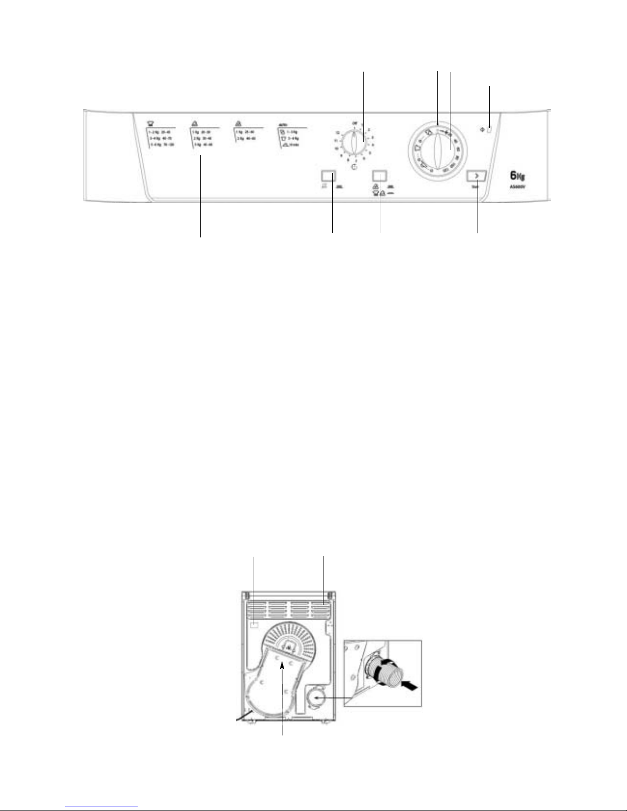
CONSOLE
NOTE: - Not all of the above functions and options are available on all models covered in this
manual.
The START button begins drying a selected
programme.
The HEAT button selects the drying
temperature.
OUT: Low Heat. IN: High Heat.
The ALARM buzzer signals the end of a
drying cycle.
OUT: Buzzer OFF. IN: Buzzer ON.
The ACTIVE indicator light signals that the
dryer is in use. This light will glow when the
START button is pressed. It will remain on
until the door is opened or the power is turned
off. this light will be on during a delayed start
programme.
The Drying Guide allows the customer to
consult a user friendly table of fabric types and
load capacities and shows a guide of the
programmes available.
The DELAY knob sets a delay on the dryers
start time, it can be rotated clockwise until you
reach the number of hours you want to delay
the start time. If you have gone too far, turn the
knob anti-clockwise.
The TIMER / PROGRAMMES knob sets the
drying time or programme. Rotate it clockwise,
never anti-clockwise, until the indicator is
pointing to the time or programme you want to
select.
p
Drying Guide
PROGRAMMES
Knob
TIMER
Knob
START
Button
Indicator
ACTIVE
Light
HEAT
Button
ALARM
Button
Air Intake Vent
Vent Tube fitted here
Caution: Hot!
Rating plate
Page 8

8
PROGRAMMES
COOLTUMBLE PHASE
This is the programmes final phase. Approximate ly 10 minutes before the finish, th ekno b advances
automatically to the Cool Tumble Phase. Heating elements turn themselves off and clothing is cooled
down, after this the buzzer will sound (if selected) and the clothing ready to be taken out.
Always allow the dryer to complete this phase.
EASY IRON PROGRAMME
Easy Iron is a short 10 minute programme (8 minutes of heat , followed by a 2 minute cool tumble
period) which fluffs the fibres of clothing that have been le ft in the same positio n/ lo ca tion for an
extended period of time. The cycle relaxes the fibres and makes them easier to iron and fold.
NOTE: - Easy Iron is not a drying programme and should not be used for wet articles of clothing.
For best results: -
1. Do not load more than the maximum capacity. These numbers refer to dry weight.
Fabric Maximum Load
Cotton and Cotton mixtures 2.5 kg
Synthetics 2 kg
Denim 2 kg
2. Unload the dryer immediately after the end of the programme, hang, fold or iron the articles and
put them away in the closet. Should this not be possible, repeat the programme.
The Easy Iron effect varies from one fabric to the next. It works well on traditional fabrics like Cotton
or Cotton mix and less well on acrylic fabrics and on materials such as Tencel®.
Programme
What it does... How to set it... Note:
Automatic
Drying
(average loads)
Dries completely:
your clothes are ready to be
worn.
For average loads (from 1 to
3kg) of Cotton , polycotton
or synthetics .
! If you select LOW HEAT,
this programme will not dry
your clothes. For Acrylic
fibres or small loads select
Timed Drying.
This programme can also be
used for large loads if you
require a slightly drier result.
1. Select HIGH HEAT
by pressing the HEAT button.
2. Position the PROGRAMMES knob
on .
3. Press the START button , the
ACTIVE light will turn on.
Automatic
Drying
(large loads)
Dries completely:
your clothes are ready to be
worn.
For large loads (from 3 to 6kg) of
Cotton .
! If you select LOW HEAT,
this programme will not dry
your clothes. For Acrylic
fibres or small loads select
Timed Drying.
This programme can also be
used for average loads if you
prefer a damper result.
Timed Drying
up to 120 minutes
Dries wet clothes that will be
ironed, Acrylic fibres , or small
loads (less than 1kg).
If you prefer a timed programme
can be used for other fabrics on
HIGH or LOW heat as appropriate
(see Laundry).
Consult suggested drying
times (see Laundry).
! This is not a drying
programme (see below).
1. Position the PROGRAMMES knob
on .
2. Press the START button , the
ACTIVE light will turn on.
Use to refresh fibres of clothing
(approximately 10 minutes).
1. Select required heat setting HIGH
HEAT or LOW HEAT by
pressing the HEAT button.
2. Position the PROGRAMMES knob
on the desired time.
3. Press the START button , the
ACTIVE light will turn on.
Easy Iron
Cool Tumble
Brief programme (approximately
10 minutes) that softens fibres of
clothing that is ready for ironing.
! This is not a drying
programme (see below).
1. Select HIGH HEAT
by pressing the HEAT button.
2. Position the PROGRAMMES knob
on .
3. Press the START button , the
ACTIVE light will turn on.
1. Select HIGH HEAT
by pressing the HEAT button.
2. Position the PROGRAMMES knob
on .
3. Press the START button , the
ACTIVE light will turn on.
Page 9

9
COMPONENT DESCRIPTION
CONSOLE PANEL
This panel contains the user controls, which consist of a timer knob, for selecting the timed and
sensed drying periods, two push switches for heat se lection an d buzzer selection and a mo mentary
switch to start the dryer. A Red LED glows to indicate when the dryer is active.
TIMER
The timer system is made up from up to three timers, two mounted on the console and one on the
kickstrip.
Timer 1 controls the motor and heater . Thi s h as a spi nd le to wh ic h a k no b i s a tta ch ed to enab le the
user to select the required programme. Timer 2 controls the motor reversing; this is mounted on the
kickstrip. Timer 3 is used to delay the start of a programme. This also has a spindle to which a knob
is attached to enable a time delay to be set by the user.
The dryer must be set to the high heat position for the Eco drying sy stem to operate fail ure to do so
will cause the timer to advance to cool run without drying the load.
Timer 1
Mounted on the console, the timer is used to control the motor and heating during the drying
programmes. The timer incorporates a timed cycle with 130 minutes of heated drying followed by a
7.5 minute cool run (137.5 minutes maximum cycle time marked as 14 0 minutes on the timer knob).
Two ’Eco' programmes are incorporated with are automatic programmes to provide heated drying
until a thermostat operates (when the load is dry), the timer then advances to a 7.5 minute cool run.
The cam of this timer is held on the heated part of the cycle by cutting the circuit to its motor.
The dryer motor continues to be reversed by timer 2. When the load is dry, a thermostat in the front
duct of the dryer operates which powers the motor of timer 1 and this allows the timer to advance to
cool run. The two 'Eco' programmes allow for diffe rent load sizes, for which different thermos tats are
selected by the timer. Timer 2 reverses the motor direction every 2.5 minutes.
An optional crease removal programme is provided, which consists of 7.5 minutes of heat and motor
followed by a cool tumble period of 2.5 minutes. All of the ab ove pr ogra mmes have the opti on of a n
external buzzer, which can sound until the timer is manually advanced.
Timer 2
Mounted on the base panel, the timer is used to control the reversal of the motor during the drying
programmes. The timer reverses the motor direction every 2.5 minutes.
Timer 3 - Not fitted to all models
This is an Electro-mechanical 12-hour timer used to delay the start of the drying cycle.
HEAT SWITCH
Normally open push-push switch. The switch locates into the facia moulding and it allows the user to
choose high or low heat settings. By consulting the wiring diagram, it can be seen that by operating
this switch, either all or half of the heater unit is selected, giving 2200W or 1100W.
For full heat switch is in the out position and low heat in the in (depressed) position.
High heat must be selected for the auto-drying programmes to operate, if low heat is selected the
dryer will advance to cool run without drying the load.
DOOR
A plastic moulded chassis with a glass bowl retained by plastic mouldings.
Page 10

10
DOOR LOCK OPERATION
DOOR SWITCH - Models AS600VXFR, AS600VEX, TVM631EUHA
Normally open single pole micro-switch activated by the door on closure. It is the first switch in the
electrical circuit and therefore its rating corresponds to the full load of the product. The switch is
integrated in the door catch assembly that allows the door to be opened from the inside.
DOOR INTERLOCK RELAY - Models AS600VXFR, AS600VEX, TVM631EUHA
The door interlock relay mounts on the rear of the front panel. The relay has double pole isolation
which acts as an additional safety feature. The relay prevents the machine from operating when the
door is closed until the start switch has bee n activated. If the door is opened duri ng a programme the
dryer will stop and will only start again when the door is closed and the start button pressed, this is a
safety requirement for tumble dryers with large door openings.
NOTE: - If the door is opened mid cycle, the machine will not restart when the door is closed.
The machine will only restart when the door is closed and then the Start button is pressed.
Bitron Door Lock Operation - Models AS600VKW, AS600AXAG
Door Open - Dryer Off
Trying to turn the machine on with the door open, the solenoid is unable to operate the bistable cam
to close the contacts, because it is locked by the latch.
Door Closed - Dryer Off
Closing the door, the latch (now rotated by the door hook) allows the movement of th e bistable cam,
but the dryer is still OFF until the solenoid is energised.
Door Closed - Dryer On
Turning the machine on with the dryer door closed, the solenoid pushes the bistable cam (freed by
the latch) allowing the closing of the contacts.
Door Opened During Drying
When the door is opened during drying, the dryer will turn off automatically by the latch in its back
rotation, this pushes back the bistable cam towards the solenoid, opening the contacts.
Re-closing the door will not restart the machine until the machine is turned back on.
Safety Function
If the latch is accidental rotated by the customer with the door open, the machine will not start.
Without the latch in position, the latch rotates 30% further and sets the bistable cam in its safety
position. The safety position will not allow the machine to start. The door will need to be manually
repositioned to reset by a Service Engineer.
door hook
bistable cam
Switch blade lever
solenoid
latch
Page 11

11
BUZZER
Eco models fitted with the Easy Care timer have a buzzer fitted which, if selected by the buzzer
switch, sounds to indicate to the user the end of a programme. The buzzer is mounted on the door
interlock relay PCB that is mounted on the rear of the console.
DRUM
The drum comprises of a zinc-coated front and rear body and two removable plastic lifters. The rear
of the drum is perforated to allow the passage of air. Fixed to the rear pressing is a support shaft,
which runs in a bearing located in the rear panel of the dryer.
A drive pin and collar on the drum shaft prevents forward thrust during use. The large front flanged
aperture rotates on bearing pads.
HEATER ELEMENT
The element comprises of front and rear pressings spaced apart with Mica type insulating material.
Through the insulating pieces are 4 runs of coiled resistance wire supported from end to end by
insulating material. High temperature insulated wires are crimped to the ends of the resistance strips
to complete the circuit.
SAFETY CUT-OUT (BLUE SPOT)
This device is a disc type thermostat set to operate at 150°C it is used as a safety device. It is
positioned above the element, to the right of the cycling thermostat on the element housing. If this
device fails it cannot be reset.
IF THIS DEVICE OPERATES, IT SHOULD BE REPLACED TOGETHER WITH THE CYCLING
THERMOSTAT (see next paragraph).
CYCLING THERMOSTAT
The cycling thermostat is mounted adjacent to the safety cut-out, is designed to open at 120°C.
It limits the temperature of the heat entering the drum.
ECO THERMOSTATS
These are of self-resetting closed disc construction, mounted in the front air duct. They control the
timer motor on timer 1. When the load is dry, the selecte d thermostat operates and powers the time r
motor; this allows the timer to advance to coo l run. The Fu ll load the rmostat ( E) is design ed to open
at 55°C and the half load (e) is designed to open at 60°C.
MOTOR
A two pole P.S.C running at 2800 rpm with the impeller fitted to the rear end of the shaft and the drive
belt running directly in grooves in the front end of the shaft. It is protected from overload by a
self-resetting internal cut-out which interrupts the electrical supply to the windings.
It is used together with a capacitor that is mounted on the base of the dryer.
DRUM REAR SEAL
This unit comprises of a ring of foam with a webbing bearing face. Lubrication is applied to the drum
where the webbing surface runs, to reduce noise and wear. The seal reduces air losses at the rear
of the drum. The joints in the foam are sealed with glue and the joints in the webbing are stitched to
further reduce air leakage.
Page 12

12
DRUM EARTHING
As the drum is supported in plastic bearings, it is necessary to provide a means of earthing.
The earthing on the drum is achi eved by the teardrop shape d bearing fixing sc rew. the correct screw
must always be used.
BELT
A 9 rib belt has been used in production. The l ength stamped on the belt is 1860 mm. This is the fitted
length. Prior to fitting, the length is approximately 1805 mm.
Page 13

13
DISMANTLING INSTRUCTIONS
SAFETY NOTES
1. Ensure that the machine is unplugged before commencing any work.
2. Beware of sharp edges on metal panels and pressed parts.
A Top Cover
1. Remove the 2 screws securing the top cover to the back panel.
2. Slide the top cover back and lift clear of the console.
B Console Panel
1. Remove the top cover as in (A).
2. Remove the 2 screws securing timer mounting plate to the console and un clip from the console.
3. Disconnect the wiring to the option switches, noting the connections.
4. Unclip the start relay from the console.
5. Remove the 2 screws securing the console to the side panels (top of console).
6. Remove the screw on the right hand side securing the front panel to the side panel.
7. Lift the locking tabs securing the console to the front panel and lift the console clear of the front
panel.
8. Remove the timer knobs from the console by depressing the locking tabs.
9. Replace in reverse order.
C Programme Timer
1. Remove the top cover as in (A).
2. Remove the 2 screws securing the timer mounting plate to the console and unclip from the
console.
3. Remove the screws securing the timer to the timer mounting plate.
4. Note the connections and disconnect the wiring to the timer.
5. When refitting the timer mounting plate to the console i t may be easier to remove the timer knobs
from the console to aid reassembly.
D Door Interlock Relay
1. Remove the right hand side panel as in (F).
2. Disconnect the wiring from the relay, noting the
connections.
3. Replace in reverse order.
E Option Switches
1. Remove the switch caps by gripping with pliers and pulling the cap off the switch shaft (care
should be taken to avoid damage to the cap when removing).
2. Note the connections and disconnect the wiring from the switch.
3. Depress the locking tabs to remove the switch from the console.
Page 14

14
FSide Panels
1. Remove the top cover as in (A).
2. Remove the plinth by pulling forward.
3. Remove the screw behind the plinth.
4. Remove the screw securing the side panel to the front panel.
5. Remove the 4 screws securing the side panel to the rear panel.
6. Pull the side panel backward to disengage from the lugs on the base panel.
G Front Panel & Air Duct
1. Remove the top cover as in (A).
2. Remove the console complete as in (B7).
3. Remove the plinth.
4. Remove the 4 screws securing the front panel to the base panel.
5. Disconnect the wiring to the air duct thermostat(s).
6. Disconnect the wiring to the door switch.
7. Remove the 2 screws securing the left hand side panel to the front panel.
I Energy Save
1. Remove the right hand side panel as in (F) above, or the front panel as in (G).
2. Disconnect the thermostat wiring and remove the 2 screws fixing the thermostat to the air duct.
J Door Switch
1. Remove the top cover as in (A).
2. Remove the right hand side panel as in (F).
3. Disconnect the wiring to the switch.
4. Using the button removal tool Part No. 5600127, depress the 2 plastic locating pips on the door
switch (taking care not break lugs) and slide the switch towards the door seal to disengage from
the front panel.
K Door Seal
1. Remove the front panel and air duct as in (G).
2. Remove the 4 screws securing the air duct to the front panel and separate the air duct from the
front panel.
3. The door seal can now be removed from the front panel.
4. Replace in reverse order.
Page 15

15
L Door
1. Open the door and remove the 4 screws secu ring the door assembly to the front panel.
2. Remove the complete door from the front panel.
3. Remove 1 screw securing the door latch to the door.
4. Remove the screw behind the door latch, securing the door handle to the door.
5. Remove the 6 screws securing the two halves of the door assembly.
6. The door trims can now be split giving access to the door bowl, handle and door hinges.
M Door Hinges
1. The door must be removed and split as in (L1) - (6) above.
2. Turn the door hinges inwards and slide the hinge upwards
to disengage from the rear trim moulding as in Fig 1.
N Front Bearings
1. Remove the front panel as in (G).
2. Spring the fixing lug out of the open slot in the
bearing mounting bracket and slide the pad along
the bracket to free the other lug as illustrated.
O Drive Belt Removal - if not broken
1. Remove the right hand side panel as in (F).
2. Place the Special Tool, Part Number 5600178, onto the motor shaft as far as possible (cut out
section to base of dryer).
3. Rotate the tool and remove the belt from the shaft.
4. Remove the front panel as in (G) and slide the belt off the drum.
Drive Belt Fitting
1. Slide the new belt onto the drum and replace the front panel.
2. Place the Special Tool , Part Number 5600266, onto the inside edge of the new belt (cut out
section of tool facing the drum).
3. Ease the special tool onto the motor shaft as far as possible.
4. Rotate the special tool in either direction to refit the belt onto the shaft.
PCapacitor
1. Remove the right hand side panel as in (F).
2. Note the wiring connections and disconnect the leads from the capacitor terminals.
3. Carefully lay the dryer on its back and remove the capacitor securing nut.
Fig. 1
Bearing Pad
Mounting Bracket
Page 16

16
Q Drum Assembly
1. Remove the top cover as in (A)
2. Remove the console as in (B)
3. Remove the front panel as in (G).
4. Remove the right hand panel to make drum removal easier.
5. Remove the rear bearing cover - 2 screws.
6. Remove one Earth strip fixing screw, slacken the other, and turn the Earth strip to allow a ccess
to the drive pin.
7. Remove the drive pin and shaft collar.
Note: When reassembling, a new drive pin must be fitted.
8. Remove the rear bearing.
9. Pull the drum clear of the rear panel.
R Motor
1. Remove the right hand side panel as in (F).
2. Remove the heater cover - 8 screws.
3. Remove the 2 fans from the motor hub - 3 hex head screws.
Note: The inner and outer fans are DIFFERENT.
Ensure fans are reassembled in the correct order.
4. Note the wiring connections and disconn ect the motor at the in-line conn ector and the capacito r.
5. Disengage the drive belt from the motor shaft as in (O2).
6. Remove the 3 hex head screws securing the motor to the motor cradle.
7. Remove the 2 screws securing the cradle to the base panel if necessary.
Note: When refitting the heater cover ensure that the heater wiring is not trapped between
the heater cover and rear panel.
Raised
Recessed Hub
Fan Orientation
Hub
Inner
Outer
Inner
Outer
Page 17

17
S Rea r Se al
1. Remove the drum as in (Q).
2. Remove the rear seal and clean any remnants of the seal and adhesive from the inner face of
the inner back panel. Fit the new seal using adhesive Part No 981027.
T Heating Assembly & Thermostats
1. Remove the right hand side panel as in (F).
2. Disconnect the wiring to the heater assembly (multi-pin connector).
3. Remove the bearing cover.
4. Remove the 8 screws securing the heater assembly to the rear panel.
5. Remove the 2 screws retaining the element and thermostats to the heater cover.
NOTE If the heater assembly has failed under the 12-month guarantee period, the complete
heater assembly should be replaced, and the faulty unit sent back via the normal Q+R
procedure.
If replacing the thermostats both the cycling and one-shot thermostat MUST be replaced should
either fail.
NOTE: - When refitting the heater cover, ensure the heater wiring Is not trapped between
the inner and outer rear panels.
URear Bearing
1. Remove the drive pin.
2. Using a small electrical screwdriver or si milar implement, carefully extract the bearing block from
the bracket on the rear panel.
From Serial Number 51103.0001 a teardrop shaped bearing was used on production.
Dismantling is similar except the bearing is secured to the back panel by a screw.
Page 18

18
SWITCH RATINGS ECO TIMER
MAIN TIMER SEQUENCE CHART ECO MODELS
CONTACT / TERMINAL RATING COMPONENT
SWITCHED
MAX.
CURRENT
Invensys EC ELBI 5000
C3 - C2 C3 - C4 16(4)A TIMER MOTOR <1A
C3 - C1 C3 - C5 16(4)A TIMER MOTOR <1A
A1 - A3/A4 B3 - B4 16(4)A MOTOR & HEATER 10A
B3/B4 - B1 A4 - A5 16(4)A HEATER 9.2A
B9/B10 - B11 B1 - B2 16(4)A BUZZER ,1A
3
140 mins
130 mins
120 mins
110 mins
100 mins
90 mins
80 mins
70 mins
60 mins
50 mins
40 mins
30 mins
20 mins
7.5 mins
123456789101112131415161718192021222324252627282930313233343536373839404142434445464748495051525354555657585960
2.5 min
2.5 min
2.5 min
2.5 min
2.5 min
2.5 min
2.5 min
2.5 min
2.5 min
2.5 min
2.5 min
2.5 min
2.5 min
2.5 min
5 min
5 min
5 min
5 min
5 min
5 min
5 min
5 min
5 min
5 min
5 min
5 min
5 min
5 min
5 min
5 min
5 min
5 min
5 min
5 min
5 min
5 min
5 min
5 min
5 min
5 min
2.5 min
2.5 min
2.5 min
Auto
C3 - C1 (C3 - C4)
Timed
C3 - C 2 (C3 -C5 )
stat select
A9 - A 11 (A1 - A 2)
*1 *1 *1
*1
Timer & Motor
A1 - A 3 (B3 - B4 )
Buzzer
B10 - B11 (B2 -B1)
Heater
B3 - B 1 (A4 - A5 )
Note *1: the programme cam should advance to the next step before the timer stops
Page 19

19
REVERSING TIMER SEQUENCE CHART FOR ECO MODELS
switch
switch
no.
1 2 3 4 5 6 7 8 9 10 1112 1314151617 18 192021222324252627282930313233343536373839404142434445464748 495051525354555657585960
1 to 2 secs - > < - - - - - - - 148 seconds +/-2 - - - - - - - - - - - >: < - 1 to 2 s econds
motor cw a - a1
mo tor acw a - a 0
<------------------------300 seconds--------------------------->
Page 20

20
WIRING DIAGRAM - MODELS TVM631EUHA, AS600VEX, AS600VXFR Invensys Timer
(GREEN SP OT)
(PURPLESPOT)
SAVE STAT-HALF
** (UPPER) ENERGY
SAVE STAT-FULL
(LOWER) ENERGY
GREEN/YELLOW
GREY
TIMER - EC
TM
B9
PB = PIGGY BACK
M = MALE TAB
=INSULATOR
WITH DELAY
VOGUE V PHD ECO
WIRING DIAGRAM
16002229407
EC Timer
SWITCH
BUZZER
HEAT SWITCH
WHITE
WHITE
GREY/BLUE
GREY
BLACK/WHITE
ORANGE
BLACK
ORANGE
STAT
CYCLING
HEATER
LOWER
UPPER
GREY/BLUE
WHITE
M
M
WHITE
TIMER
REVERS'G
TM
BROW
E
N
L
WITH SUPPRESSION
MAINS CONNECTION
BLUE
RED /
ORANGE
BLACK
WHITE
MOTOR
BLACK
RED
M
-ITOR
CAPAC
PB
PB
M
M
BROWN
BLUE
ONE SHOT
CUT OUT
5
3
4
8
ZBN
PB
A1
A3/A4
B4
B3
B1
C2
C3
C1
A11
A9/A10
RED
B11
** UPPER STAT POSITION IS NEXT TO FRONT TO BACK TUBE.
TIMER
DELAY
TM
a
a0
a1
THERMOSTAT
EARTHING
PLATE
START SWITCHSTART SWITCH
BROWN
BLACK
BUZZER
PINK/WHITE
BLUE
1BLUE
RED
BROWN
NEON
GREY/BLUE
BLUE
WHITE
BLACK/WHITE
REAR VIEW OF CONNECT OR FOR HEATER
4
4
4
123
21
3
12 113
11
11
5678910
576
567
9810
8910
12A12
12
B
C
PINK / WHITE
BLUE
GREY
BLACK / WHITE
WHITE
GREY / BLUE
BROWN
GREY
RED
Invensys EC4208/4209 Wiring
B
L
U
E
BLACK
PINK/WHITE
BLUE
BROWN
BLUE
GREY
BLUE
BLUE
DOOR SWITCH
A
B
BROWN
476
9
PINK/WHITE
5407394wd1.pdf
TMS631EUHA, AS600VEX, AS600AXFR
16002229407_1
Page 21

21
WIRING DIAGRAM - MODELS TVM631EUHA, AS600VEX, AS600VXFR Elbi Timer
(GREEN SP OT)
(PURPLESPOT)
SAVE STAT -HALF
** (UPPER) ENERGY
SAVE STA T-FULL
(LOWER) ENERGY
GREEN/YELLOW
16001801900
TIMER - ELBI
TM
C2
PB = PIGGY BACK
M = MALE TAB
WITH DELAY
VOGUE V PHD ECO
WIRING DIAGRAM
16002229407
Elbi 5000
SWITCH
BUZZER
HEAT SWITCH
WHITE
WHITE
GREY/BLUE
GREY
BLACK/WHITE
ORANGE
BLACK
ORANGE
STAT
CYCLING
HEATER
LOWER
UPPER
GREY/BLUE
WHITE
M
M
WHITE
TIMER
REVERS'G
TM
E
N
L
WITH SUPPRESSION
MAINS CONNECTION
BLUE
RED/
ORANGE
BLACK
WHITE
MOTOR
BLACK
RED
M
-ITOR
CAPAC
PB
PB
M
M
BROWN
BLUE
ONE SHOT
CUT OUT
5
3
4
8
ZBN
PB
B3
B4
A4
C5
C3
C4
A2
FA1
B1
** UPPER STAT POSITION IS NEXT TO FRONT TO BACK TUBE.
TIMER
DELAY
TM
a
a0
a1
THERMO STAT
EARTHING
PLATE
BROWN
BLACK
BUZZER
PINK/WHITE
BLUE
RED
BROWN
NEON
GREY/BLUE
BLUE
WHITE
BLACK/WH ITE
BLUE
BLACK
BLACK / WHITE
PINK / WHITE
GREY / BLUE
WHITE
BROWN
A
B
C
GREY
ELBI TIMER 5000 - 09 098230XX
09 098240XXX
REAR VIEW OF CONNECT OR FOR HEATER
=INSULATOR
F=FLAG
GREY
BLUE
A5
F
F
B2
GREY
BLUE
F
BROWN
START SWITCHSTART SWITCH
PINK/WHITE
BROWN
BLUE
GREY
BLUE
BLUE
DOOR SWITCH
BROWN
A
B
4
7
6
9
PINK/WHITE
5407394wd2.pdf
TVM631EUHA, AS600VEX, AS600VXFR
16002229407_2
Page 22

22
WIRING DIAGRAM - MODELS AS600VXAG, AS600VKW Invensys Timer
(GREEN SPOT)
(PURPLE SPOT)
SAVE STAT-HALF
** (UPPER) ENERGY
SAVE STAT-FULL
(LOWER) ENERGY
GREEN/YELLOW
GREY
TIMER - EC
TM
B9(B2)
PB = PIGGY BACK
M = MALE TAB
= INSULATOR
WITH DELAY
VOGUE IV PHD ECO
WIRING DIAGRAM
16002212003 EC TIMER
SWITCH
BUZZER
HEAT SWITCH
WHITE
WHITE
GREY/BLUE
GREY
BLACK/WHITE
ORANGE
BLACK
ORANGE
STAT
CYCLING
HEATER
LOWER
UPPER
GREY/BLUE
WHITE
M
M
GREY/BLUE
TIMER
REVERS'G
TM
BROWN
BLUE
E
N
L
WITH SUPPRESSION
MAINS CONNECTION
A
BLUE
RED/
ORANGE
BLACK
WHITE
MOTOR
BLUE
BLACK
RED
A0
A1
M
-ITOR
CAPAC
PB
PB
M
M
BROWN
BLUE
ONE SHOT
CUT OUT
(5)
(3)
(4)
(8)
PEAPSA (ZBN)
PB
A1
A3/A4
B4
B3
B1
C2
C3
C1
A11
A9/A10
RED *
B11(B1)
** UPPER STAT POSITION IS NEXT TO FRONT TO BACK TUBE.
TIMER
DELAY
TM
a
a0
a1
THERMOSTAT
EARTHING
PLATE
SOLENOID
PTC
3
4
5
START SWITCHSTART SWITCH
BROWN
BLACK
BUZZER
PINK/WHITE
BLUE
BLUE
BLUE
GREY
BLACK
RED
BROWN
NEON
BLUE
GREY/BLUE
BLUE
WHITE
BLACK/WHITE
REAR VIEW OFCONNECTOR FOR HEATER
444
123
21 3
12 113
11
11
5678910
576
567
9810
8910
12A12
12
B
C
BROWN/WHITE
BLUE
GREY
BLACK/WHITE
WHITE
WHITE
BLUE
Invensys EC4208/4209 Wiring
GREY/BLUE
BROWN
GREY
RED
5407394wd3.pdf
AS600VXAG, AS600VKW
16002212003_1
Page 23

23
WIRING DIAGRAM - MODELS AS600VXAG, AS600VKW Elbi Timer
ELBI TIMER 5000 - 09830XX
09840XX
BLACK/WHITE
GREY
BROWN/WHITE
GREY/BLUE
WHITE
WHITE
BROWN
BLUE
BLUE
GREY
A
B
C
(GREEN SPOT)
(PURPLE SPOT)
SAVE STAT-HALF
** (UPPER) ENERGY
SAVE STAT-FULL
(LOWER) ENERGY
GREEN/YELLOW
16001801900
GREY
TIMER - ELBI
TM
C2
PB = PIGGY BACK
M = MALE TAB
= INSULATOR
WITH DELAY
VOGUE V PHD ECO
WIRING DIAGRAM
16002212003 ELBI 5000
SWITCH
BUZZER
HEAT SWITCH
WHITE
WHITE
16002216000
GREY/BLUE
16002215900
GREY
16002215800
BLACK/WHITE
16002213900
ORANGE
BLACK
ORANGE
STAT
CYCLING
HEATER
LOWER
UPPER
GREY/BLUE
WHITE
16002214000
M
M
GREY/BLUE
TIMER
REVERS'G
TM
BROWN
16001967501
BLUE
E
N
L
WITH SUPPRESSION
MAINS CONNECTION
16001804401
A
BLUE
RED/
ORANGE
BLACK
WHITE
MOTOR
BLUE
BLACK
16001784801
RED
16001804300
A0
A1
M
-ITOR
CAPAC
PB
PB
M
M
BROWN
BLUE
ONE SHOT
CUT OUT
(5)
(3)
(4)
(8)
PEAPSA (ZBN)
PB
16002216201
B3
B2
A4
B3
A5
C5
C3
C1 (C4)
A2
A1
B1
** UPPER STAT POSITION IS NEXT TO FRONT TO BACK TUBE.
TIMER
DELAY
TM
a
a0
a1
THERMOSTAT
EARTHING
PLATE
SOLENOID
PTC
3
4
5
START SWITCHSTARTSWITCH
16002215700
BROWN
16002078900
BLACK
BUZZER
16002215400 PINK/WHITE
BLUE
16002216800 BLUE
16002215600 BLUE
16002213400
GREY
BLACK
RED
16002215501
BROWN
NEON
BLUE
F
F
F
F
B4
GREY/BLUE
BLUE
WHITE
BLACK/WHITE
REAR VIEW OF CONNECTORFOR HEATER
5407394wd4.pdf
AS600VAG, AS600VKW
16002212003_2
 Loading...