


 Loading...
Ariens 915013-EZR 1742, 915014-EZR 2048, 915017-EZR 1542, 915018-EZR 1842, 915307-EZR 1742 User Manual
EZR® Zero Turn Mower
Parts Manual
Models
915013-EZR 1742
915014-EZR 2048
915017-EZR 1542
915018-EZR 1842
915307-EZR 1742
01562900C 5/01 Supercedes 01562900, A,B Printed in USA

THE MANUAL
Before you operate your unit, carefully and completely read manuals supplied with the unit. The contents will provide you with an understanding of safety instructions and controls during normal operation and maintenance.
For your safety and the safety of others always read, understand, and follow all DANGER, WARNING, and CAUTION messages found in manuals and on safety decals.
Hardware descriptions are given in decimals.
Decimals to Fractions
.063 |
1/16 |
|
.563 |
9/16 |
|
|
|
|
|
.125 |
1/8 |
|
.625 |
5/8 |
|
|
|
|
|
.188 |
3/16 |
|
.688 |
11/16 |
|
|
|
|
|
.250 |
1/4 |
|
.750 |
3/4 |
|
|
|
|
|
.313 |
5/16 |
|
.813 |
13/16 |
|
|
|
|
|
.375 |
3/8 |
|
.875 |
7/8 |
|
|
|
|
|
.438 |
7/16 |
|
.938 |
15/16 |
|
|
|
|
|
.500 |
1/2 |
|
1.00 |
1 |
|
|
|
|
|
SERVICE AND REPLACEMENT PARTS
When ordering replacement parts or making service inquiries, know the Model and Serial numbers of your unit and engine.
Numbers are located on the product registration card in the unit literature package. They are printed on a serial number label, located on the frame of your unit.
•Record Unit Model and Serial numbers here:
•Record Engine Model and Serial numbers here:
PRODUCT REGISTRATION
A warranty registration card must be filled out, signed, and returned at time of purchase. This card activates the warranty. Claims meeting requirements during limited warranty period will be honored.
YOUR SATISFACTION IS IMPORTANT
Questions? Please follow these helpful steps:
1.Refer to the manuals supplied with your unit.
They will guide you through safe and proper operation and maintenance.
They contain specifications on your unit.
If your questions are not answered in these manuals, go to step number two.
2.Contact Your Dealer.
Our dealers will be happy to supply any service or advice required to keep your unit operating at peak efficiency.
A factory trained staff is available to support your equipment needs. They stock genuine Ariens parts and lubricants manufactured with the same precision and skill as the original.
If your questions are not resolved by the support staff, ask for the manager or owner.
When contacting your Dealer supply your model and serial numbers.
TO SPEED PARTS ORDERING:
1.Know the model and serial numbers of your unit.
2.Know the part number required.
3.Know the quantity required.
4.Know the part description.
UNAUTHORIZED REPLACEMENT PARTS
Use only Ariens replacement parts. The replacement of any part on this vehicle with anything other than an Ariens authorized replacement part may adversely affect the performance, durability, or safety of this unit and may void the warranty. Ariens disclaims liability for any claims or damages, whether warranty, property damage, personal injury or death arising out of the use of unauthorized replacement parts.
2

MODELS
Model 915013 (EZR 1742)
17.0 HP Briggs & Stratton with 42" Mower Serial No. 005904 and up
Model 915014 (EZR 2048)
20.0 HP Briggs & Stratton with 48" Mower Serial No. 001103 and up
Model 915017 (EZR 1542)
15.0 HP Briggs & Stratton with 42" Mower Serial No. 000101 and up
Model 915018 (EZR 1842)
18.0 HP Briggs & Stratton with 42" Mower Serial No. 000101 and up
Model 915307 (EZR 1742)
17.0 HP Briggs & Stratton with 42" Mower Serial No. 000114 and up
TABLE OF CONTENTS
DECALS
Decals . . . . . . . . . . . . . . . . . . . . . . . . . . . . . . . . . . . . 4
POWER PLANT
Clutch Shaft-Hydro. . . . . . . . . . . . . . . . . . . . . . . . . . . 6
Parking Brake and Dump Valves . . . . . . . . . . . . . . . . 7
HydroStatic Transaxle-Right. . . . . . . . . . . . . . . . . . . . 8
HydroStatic Transaxle-Left . . . . . . . . . . . . . . . . . . . . 10
Transaxles and Wheels . . . . . . . . . . . . . . . . . . . . . . 12
Engine, Exhaust and Belts . . . . . . . . . . . . . . . . . . . . 15
Idlers . . . . . . . . . . . . . . . . . . . . . . . . . . . . . . . . . . . . 16
MAIN FRAME
Frame . . . . . . . . . . . . . . . . . . . . . . . . . . . . . . . . . . . 17
Seat and Support . . . . . . . . . . . . . . . . . . . . . . . . . . . 18
Fuel Tank . . . . . . . . . . . . . . . . . . . . . . . . . . . . . . . . . 19
Front Axle. . . . . . . . . . . . . . . . . . . . . . . . . . . . . . . . . 20
Bumpers. . . . . . . . . . . . . . . . . . . . . . . . . . . . . . . . . . 21
Cover Assembly, Solenoid and Switches . . . . . . . . . 22
OPERATOR CONTROLS
Controls . . . . . . . . . . . . . . . . . . . . . . . . . . . . . . . . . . 24
Attachment Lift . . . . . . . . . . . . . . . . . . . . . . . . . . . . . 26
Hanger Arm (48” Deck Only) . . . . . . . . . . . . . . . . . . 27
ELECTRICAL SYSTEM
Continuity Diagrams. . . . . . . . . . . . . . . . . . . . . . . . . 28
Wiring Diagrams. . . . . . . . . . . . . . . . . . . . . . . . . . . . 29
MOWER DECKS |
|
42” Mower Deck . . . . . . . . . . . . . . . . . . . . . . . . . . . |
30 |
42” Mower Brackets and Rollers . . . . . . . . . . . . . . . |
31 |
42” Mower Spindle . . . . . . . . . . . . . . . . . . . . . . . . . . |
32 |
48” Mower Spindle . . . . . . . . . . . . . . . . . . . . . . . . . . |
34 |
48” Mower Pan . . . . . . . . . . . . . . . . . . . . . . . . . . . . . |
36 |
3 |
© Copyright 2001 Ariens Company |

DECALS-SAFETY
Model 915013, 014, 017, 018, 307
1 |
2 |
13 |
|
2 |
|
12 |
|||
|
|
|
|
2
077541
3
 WARNING/AVERTISSEMENT/ADVERTENCIA
FOR SAFE DECK REMOVAL/POUR UNE DÉPOSE DU CARTER DE COUPE EN TOUTE SÉCURITÉ /PARA LA EXTRACCION´ SEGURA DE LA PLATAFORMA |
|
||
1 |
|
|
|
5 |
1 |
|
|
4 |
|
|
|
3 |
|
|
|
2 |
|
|
|
1 |
2 |
|
|
|
|
|
|
2 |
3 |
052240 |
8 |
|
|
|
|
4 |
7/8” (22mm) 2 |
|
3 |
|
1 |
1
3
After proper belt installation:
1.Marks must align as shown.
2.Distance must be 7/8” (22mm) and you must be able to rotate outer spacer with thumb and forefinger.
3.These three nuts must be tightened.
Après la pose correcte de la courroie :
1.Les repères doivent être alignées (voir schéma).
2.La distance doit être de 22 mm (7/8 in.) et il doit être possible de tourner l'entretoise externe avec le pouce et l'index.
3.Ces trois écrous doivent être serrés.
Después de la instalación adecuada de la correa:
1.Las marcas deben alinearse como se muestra.
2.La distancia debe ser de 22 mm (7/8 pulg.) y be de ser capaz de rotar el espaciador externo con los dedos pulgar e índice.
3. Estas tres tuercas deben apretarse. |
05226200B |
8  DANGER / PELIGRO
10
 DANGER / PELIGRO
07731400D |
11 |
6
7
07731400D
9 |
WARNING/AVERTISSEMENT/ADVERTENCIA |
||
|
Do not operate mower |
Ne jamais utiliser |
No operar segadora a |
|
unless guards are in |
la tondeuse sans |
menos que las defensas |
|
operating position or |
protecteur sur le |
esten en posicion de |
|
bagger is attached. |
canal d'ejection ou |
operacion o el |
|
07742300B |
sans le bac monte. |
recogedor este fijo. |
5 |
078000 |
PE0571
Item |
Part No. |
Qty. |
Description |
1 |
07754100 |
1 |
Decal-Hot Surface (013, 017, 307) |
|
07754100 |
2 |
Decal-Hot Surface (014, 018) |
2 |
61518400 |
1 |
Decal-Instructional Set |
3 |
05224000 |
1 |
Decal-Safe Deck Removal |
4 |
05226200 |
1 |
Decal, Belt Diagram (013, 017, 018, 307) |
5 |
07757800 |
1 |
Decal-Bilingual Danger (013, 017) |
|
07800000 |
1 |
Decal-Bilingual Danger (014, 018, 307) |
6 |
01556700 |
1 |
Non-Skid Cover |
7 |
01528000 |
1 |
Non-Skid Cover (013, 017) |
|
01556600 |
1 |
Non-Skid Cover (014, 018, 307) |
8 |
07731400 |
2 |
Decal, Mower Pan Head Danger |
9 |
07742300 |
1 |
Decal, Warning |
10 |
05226300 |
1 |
Decal, Blade Alignment |
11 |
05226900 |
1 |
DecalSafe Deck Removal, Export (307) |
12 |
07757600 |
1 |
Decal-Instructional Steering |
13 |
07757500 |
1 |
Decal, Parking Brake Lever |
|
|
|
|
|
|
|
4 |
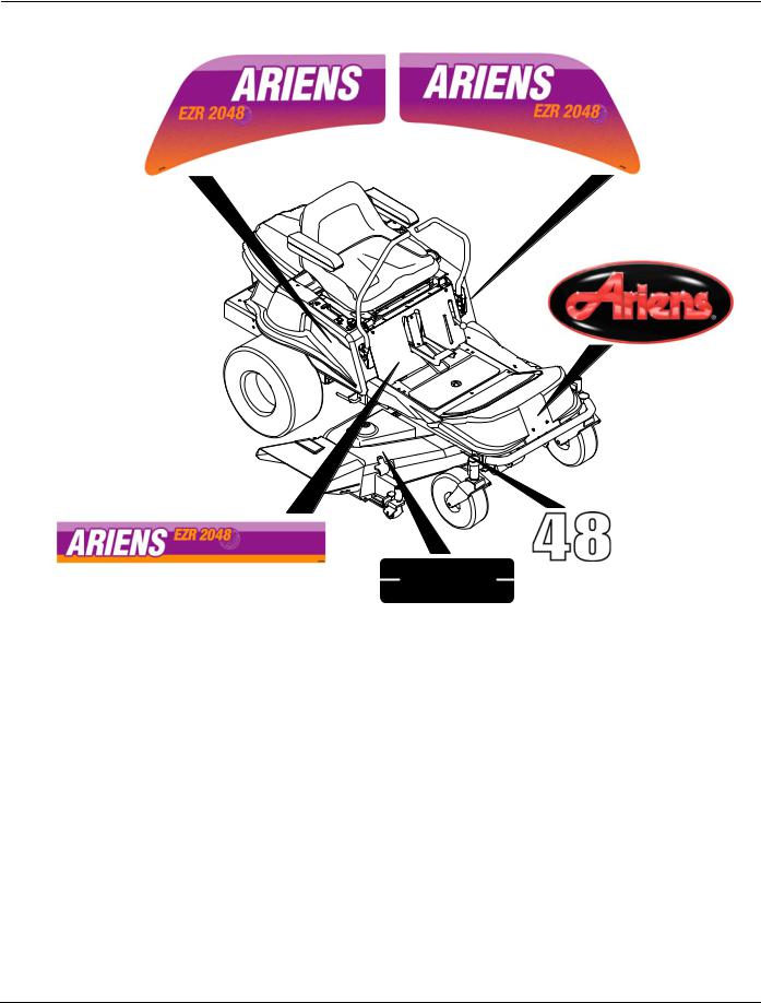
DECALS-STYLE
Model 915013, 014, 017, 018, 307
1
1
2
1
3
4
LARGEUR DE COUPE
WIDTH OF CUT
ANCHURA DEL CORTE
07852100A
Item |
Part No. |
Qty. |
Description |
|
1 |
61514400 |
1 |
Decal, Set EZR 2048 (014) |
|
|
61514300 |
1 |
Decal, Set EZR 1742 (013, 307) |
|
|
61517700 |
1 |
Decal, Set EZR 1542 (017) |
|
|
61517800 |
1 |
Decal, Set EZR 1842 (018) |
|
2 |
07746400 |
1 |
Decal, Ariens Jewel Oval |
|
3 |
05233300 |
1 |
Decal, 48 |
(014) |
|
05233200 |
1 |
Decal, 42 |
(013, 017, 018, 307) |
4 |
07852100 |
1 |
Decal, Width of Cut (014) |
|
5
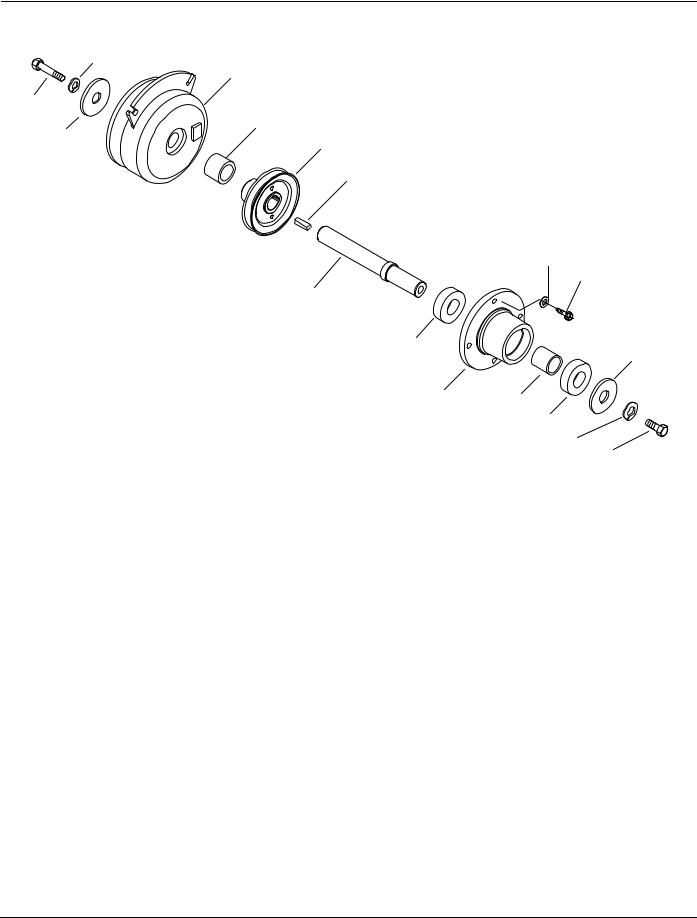
CLUTCH SHAFT-HYDRO
Model 915013, 014, 017, 018, 307
2
4
1
5
3
6
7
15
11
8
9
13
10 12
9
2
14 |
PE0370 |
Item |
Part No. |
Qty. |
Description |
1 |
05965600 |
1 |
Bolt-Hex .44-20 x 1.50 Grade 5 (014) |
|
05964600 |
1 |
Bolt-Hex .44-20 x 2.50 Grade 5 (013, 017, 018, 307) |
2 |
06309300 |
1 |
Washer-Locking .44 x .109 |
3 |
06443600 |
1 |
Washer-Flat-Steel .469 x 2.00 x .25 |
4 |
03357900 |
1 |
Clutch-Electric/Brake (014) |
|
03643100 |
1 |
Clutch-Electric/Brake (013, 017, 018, 307) |
5 |
01531400 |
1 |
Spacer 1.004 x 1.500 x .740 (014) |
6 |
01558100 |
1 |
Sheave-Jackshaft 4.50 (014) |
|
01557500 |
1 |
SheaveJackshaft 4.50 (013, 017, 018, 307) |
7 |
06602200 |
1 |
Key-Square .25 x 1.00 x .25 SAE (014) |
|
06602700 |
1 |
Key-Square .25 x 1.00 x .25 SAE (013, 017, 018, 307) |
8 |
01558000 |
1 |
Shaft-Jack (014) |
|
01557600 |
1 |
Shaft-Jack (013, 017, 018, 307) |
9 |
05421500 |
2 |
Bearing-Ball .984 x 2.04 x .59 |
10 |
00506751 |
1 |
Housing-Transmission Spindle |
11 |
07414400 |
4 |
Screw-Tapping .31-18 x .75 Hex Washer Head |
12 |
00506800 |
1 |
Spacer 1.00 x .253 x 1.26 |
13 |
06443500 |
1 |
Washer-Flat-Steel .463 x 1.38 x .25 |
14 |
05964500 |
1 |
Bolt-Hex .44-20 x 1.00 Grade 5 |
15 |
06437500 |
4 |
Washer-Flat-Steel .328 x 1.00 x .094 |
6
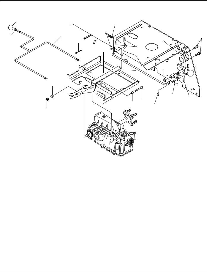
PARKING BRAKE AND DUMP VALVES
|
Model 915013, 014, 017, 018, 307 |
2 |
7 |
|
|
4 |
15 |
3 |
5 |
|
|
|
|
14 |
|
|
|
|
|
||
|
|
|
|
|
|
|
|
|
6 |
|
|
8 |
|
|
|
|
|
|
|
|
|
|
|
|
|
|
2 |
|
|
|
1 |
|
|
12 |
|
|
|
|
|
|
|
|
10 |
|
|
|
|
|
|
|
|
|
|
|
13 |
|
|
|
|
10 |
9 |
8 |
|
|
|
|
|
||
|
|
|
|
|
8 |
|
|
|
|
|
|
|
|
|
11 |
|
|
|
|
|
PE0380
Item |
Part No. |
Qty. |
Description |
1 |
01555600 |
1 |
Rod-Brake |
2 |
07515900 |
2 |
Knob |
3 |
06529200 |
1 |
Nut-Hex .31-18 |
4 |
01540100 |
1 |
Dump Valve Weldment |
5 |
06713500 |
2 |
Pin-Cotter .09 x .75 |
6 |
01545300 |
1 |
Brake Arm Weldment |
7 |
08325200 |
1 |
Spring-Tension .051 x .60 x 2.25 |
8 |
06713500 |
4 |
Pin-Hair Internal .08 x .18 x 1.18 |
9 |
05966300 |
1 |
Bolt-Hex .25-20 x 3.00 |
10 |
05521000 |
2 |
Bushing-Flange .257 x .38 x 1.080 |
11 |
06529700 |
1 |
Nut-Locking-Center .25-20 |
12 |
05717100 |
1 |
Ring-Retaining External .50 x .050 |
13 |
01555900 |
1 |
Lever-Brake |
14 |
01555800 |
1 |
Pivot-Brake Lever |
15 |
05946900 |
2 |
Bolt-Hex .31-18 x 1.00 Grade 5 |
7
HYDROSTATIC TRANSAXLE-RIGHT
Model 915013, 014, 017, 018, 307
53
55
57
56
48
59 58
|
3 |
|
|
4 |
5 |
|
2 |
|
|
6 |
|
1 |
|
|
|
|
|
47 |
46 |
|
|
|
|
14 |
|
60 |
45 |
|
|
44 |
|
|
12 |
40 |
30 |
|
||
|
43 |
|
49 |
42 |
38 |
|
|
51 |
|
|
|
48 |
39 |
|
|
|
50 |
|
41 |
52 |
|
|
|
38 |
|
|
|
54
1
Item |
Part No. |
Description |
1 |
50437 |
Screw .25-20 x .75 |
2 |
50891RM |
Cover-Back |
3 |
44870 |
Ring-Retaining |
4 |
50270 |
Arm-Bypass |
5 |
45074 |
Seal-Lip |
6 |
9005200-5600 |
Plug-Plastic |
7 |
2003052 |
Ring-Retaining |
8 |
9008000-0128 |
Seal-Lip |
9 |
2003018 |
Spacer |
10 |
2003016 |
Ring-Wire Retaining |
11 |
2003043 |
Bearing-Ball |
7
8 13
9 12
10
11
19
25
21
26
27
29 28
31
32
33
34
35
36
37
14
16
15
17
18
20
22
23
24
PE0490
Part Numbers listed on this page are Hydro Gear part numbers and are to be ordered or purchased from the nearest Hydro Gear Dealer, which may be found in the Yellow Pages of the Telephone Directory.
8

HYDROSTATIC TRANSAXLE-RIGHT
Model 915013, 014, 017, 018, 307
Item |
Part No. |
Description |
12 |
50315 |
Bearing-Ball |
13 |
50329 |
Ring-Retaining |
14 |
50735 |
Seal-Brake Shaft |
15 |
50754 |
Brake Disc |
16 |
70394 |
Kit-Retaining Ring |
17 |
51076 |
Screw-Hex Washer Head 1/4-20 x 7/8 |
18 |
70392 |
Service Assembly-Right Hand Brake Arm |
19 |
50426 |
Stud-Short 5/16-24 |
20 |
50281 |
Friction Puck |
21 |
90080000-0126 Seal-Lip |
|
22 |
50749 |
Arm-Control |
23 |
44130 |
Washer |
24 |
50317 |
Nut |
25 |
2003023 |
Cradle Bearing |
26 |
2003087 |
Variable Swashplate |
27 |
2000015 |
Slot Guide |
28 |
50807 |
Arm-Trunnion |
29 |
50551 |
Bearing-Thrust 30 x 52 x 13 |
30 |
50005 |
Shaft-Input |
31 |
2003017 |
Washer-Block Thrust |
32 |
2003014 |
Spring-Block |
33 |
70331 |
Assembly-Cylinder Block 10cc |
34 |
70340 |
Assembly-Center Section |
35 |
50016 |
Screw |
36 |
50990 |
Filter |
37 |
50890RM |
Housing-Lower |
38 |
50002 |
Pin-Alignment |
39 |
2003554 |
Bypass Plate |
40 |
2003555 |
Bypass Actuator |
41 |
70082 |
Assembly-Cylinder Block 21cc |
42 |
50757 |
Shaft-Motor |
43 |
50552 |
Bearing-Thrust 42 x 68 x 16 |
44 |
2000022 |
Ring-Wire Retaining |
45 |
50744 |
Gear-Bevel 14T |
46 |
70393 |
Kit-Brake Shaft |
47 |
50745 |
Gear-Bevel 19T |
48 |
50760 |
Ring-Retaining - Axle |
49 |
50995 |
Seal-Plug - Side |
50 |
50759 |
Ring-Retaining - Axle |
51 |
50743 |
Bearing-Ball 20 x 47 x 14 |
52 |
50942-2 |
Bushing-Axle |
53 |
50746 |
Gear-Spur 53T |
54 |
50942-1 |
Bushing-Axle |
55 |
50748 |
Shaft-Axle |
56 |
50740 |
Bearing-Ball 25 x 47 x 12 |
57 |
50751 |
Seal |
58 |
70314 |
Assembly-Hub |
59 |
50863 |
Nut-Hex 3/4-16 |
60 |
70329 |
Housing-Upper Assembly |
9

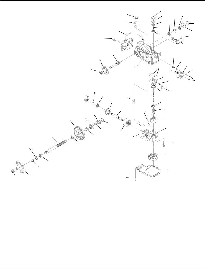
HYDROSTATIC TRANSAXLE-LEFT
Model 915013, 014, 017, 018, 307
|
|
|
3 |
7 |
|
|
|
|
|
|
|
|
|
|
|
|
|
|
4 |
8 |
14 |
|
|
|
|
|
9 |
|
|
||
|
|
|
|
|
20 |
||
|
|
|
5 |
|
|
||
|
1 |
2 |
10 |
|
|
|
|
|
|
|
|
|
|
||
|
|
|
|
13 |
|
|
|
|
|
|
6 |
11 |
|
|
|
60 |
|
|
|
|
12 |
|
21 |
|
|
|
|
|
|
|
|
|
|
|
|
33 |
|
|
19 |
|
|
|
|
|
|
18 |
|
59 |
55 |
|
|
|
15 |
16 |
17 |
57 |
|
|
|
34 |
|
27 |
28 |
|
|
|
35 |
|
|
||
|
|
|
|
|
|
||
58 |
|
|
|
|
|
31 |
|
|
56 |
|
36 |
|
|
||
14 |
|
29 |
|
|
|||
|
|
|
|
||||
|
|
|
|
|
|
||
54 |
|
|
|
37 |
|
|
|
|
|
|
38 |
30 |
|
32 |
|
|
12 |
|
|
|
|||
|
|
49 |
39 |
|
|
|
|
|
|
|
|
|
|
||
|
|
|
40 |
|
|
|
|
|
|
|
|
|
|
|
|
53 |
|
|
47 |
41 |
|
|
|
|
52 |
|
48 |
42 |
|
|
|
|
|
|
|
|
|
|
51 |
43 |
|
|
|
50 |
|
44 |
45
46
|
|
1 |
Item |
Part No. |
Description |
1 |
50437 |
Screw 1/4-20 x .75 |
2 |
50891RM |
Cover-Back |
3 |
44870 |
Ring-Retaining |
4 |
50270 |
Arm-Bypass |
5 |
45074 |
Seal-Lip |
6 |
9005200-5600 |
Plug-Plastic |
7 |
2003052 |
Ring-Retaining |
8 |
9008000-0128 |
Seal-Lip |
9 |
2003018 |
Spacer |
10 |
2003016 |
Ring-Wire Retaining |
15
23
26
24 25
22
PE0480
Part Numbers listed on this page are Hydro Gear part numbers and are to be ordered or purchased from the nearest Hydro Gear Dealer, which may be found in the Yellow Pages of the Telephone Directory.
10
HYDROSTATIC TRANSAXLE-LEFT
Model 915013, 014, 017, 018, 307
Item |
Part No. |
Description |
11 |
2003043 |
Bearing-Ball |
12 |
50315 |
Bearing-Ball |
13 |
50329 |
Ring-Retaining |
14 |
50735 |
Seal-Brake Shaft |
15 |
50760 |
Ring-Retaining - Axle |
16 |
50995 |
Seal-Plug - Side |
17 |
50759 |
Ring-Retaining - Axle |
18 |
50743 |
Bearing-Ball 20 x 47 x 14 |
19 |
50942-1 |
Bushing-Axle |
20 |
50746 |
Gear-Spur 53T |
21 |
50942-2 |
Bushing-Axle |
22 |
50748 |
Shaft-Axle |
23 |
50740 |
Bearing-Ball 25 x 47 x 12 |
24 |
50751 |
Seal |
25 |
70314 |
Assembly-Hub |
26 |
50863 |
Nut-Hex 3/4-16 |
27 |
50426 |
Stud-Short 5/16-24 |
28 |
50281 |
Friction Puck |
29 |
90080000-0126 |
Seal, Lip |
30 |
50749 |
Arm-Control |
31 |
44130 |
Washer |
32 |
50317 |
Nut |
33 |
70329 |
Assembly-Upper Housing |
34 |
2003023 |
Bearing-Cradle |
35 |
2003087 |
Variable Swashplate |
36 |
2000015 |
Slot Guide |
37 |
50807 |
Arm-Trunnion |
38 |
50551 |
Bearing-Thrust 30 x 52 x 13 |
39 |
50005 |
Shaft-Input |
40 |
2003017 |
Washer-Block Thrust |
41 |
2003014 |
Spring-Block |
42 |
70331 |
Assembly-Cylinder Block 10cc |
43 |
70340 |
Assembly-Center Section |
44 |
50016 |
Screw |
45 |
50990 |
Filter |
46 |
50890RM |
Housing-Lower |
47 |
50002 |
Pin-Alignment |
48 |
2003554 |
Bypass Plate |
49 |
2003555 |
Bypass Actuator |
50 |
70082 |
Assembly-Cylinder Block 21cc |
51 |
50757 |
Shaft-Motor |
52 |
50552 |
Bearing-Thrust 42 x 68 x 16 |
53 |
2000022 |
Ring-Wire Retaining |
54 |
50744 |
Gear-Bevel 14T |
55 |
70393 |
Kit, Brake Shaft |
56 |
50745 |
Gear-Bevel 19T |
57 |
50754 |
Brake Disc |
58 |
70394 |
Ring-Retaining |
59 |
51076 |
Screw-He-Washer-Head 1/4-20 x 7/8 |
60 |
70391 |
Assembly-Left Hand Brake Arm |
11

TRANSAXLE AND WHEELS
Model 915013, 014, 017, 018, 307
|
4 |
4 |
|
|
|
13 |
11 |
4 |
|
|
|
10 |
9 |
|
|
12 |
7 |
16 |
8 |
6 |
|
17 |
1
2
15
5
14
3
|
|
|
3 |
3 |
Item |
Part No. |
Qty. |
Description |
|
1 |
01540300 |
1 |
Transaxle Hydro-Gear Right Hand |
|
2 |
01540400 |
1 |
Transaxle Hydro-Gear Left Hand |
|
3 |
05952600 |
12 |
Bolt-Hex .31-18 x 2.50 Grade 5 |
|
4 |
06529800 |
12 |
Nut-Locking-Center .31-18 |
|
5 |
01543900 |
1 |
Transaxle Bracket |
|
6 |
01543100 |
2 |
Hose-Vent |
|
7 |
03570000 |
2 |
Fan |
|
8 |
07413000 |
8 |
Screw-Tapping 10-24 x .75 Hex Washer Head |
|
9 |
07321400 |
2 |
Sheave-Transaxle |
|
10 |
06517200 |
2 |
Nut-Locking-Top .50-20 |
|
11 |
01540900 |
1 |
Transmission Cradle |
|
12 |
05959400 |
8 |
Bolt-Hex .38-16 x .75 Grade 5 |
|
13 |
06529600 |
8 |
Nut-Locking-Center .38-16 |
|
14 |
07144600 |
2 |
Tire/Wheel 18 x 8.50-8 |
|
|
07144900 |
AR |
Rim for 18 x 8.50-8 Tire |
|
|
07145100 |
AR |
Tire 18 x 8.50-8 |
|
15 |
06535000 |
8 |
Nut-Lug .50-20 |
|
16 |
07026400 |
1 |
Cap-Vent 1/2" Hydro-Gear |
|
17 |
07026300 |
1 |
Fitting-Straight 1/2" O-Ring Hydro-Gear |
|
PE0221
12
Loading...