

Operating and installation instructions
Y-pattern processing valve - STEVI®AS 350
DN 15 - 50
Contents
1.0 General information on operating
instructions ..................................................2-2
2.0 Notes on possible dangers.........................2-2
2.1 Significance of symbols ...................................... 2-2
2.2 Explanatory notes on safety information ............. 2-2
3.0 Storage and transport ................................ 2-2
4.0 Description...................................................2-3
4.1 Scope of applications .......................................... 2-3
4.2 Operating principles ............................................ 2-3
4.3 Diagram............................................................... 2-5
4.4 Technical data ..................................................... 2-5
4.5 Marking ............................................................... 2-6
5.0 Installation....................................................2-7
5.1 General notes on installation............................... 2-7
5.2 Requirements at the place of installation ............ 2-8
5.3 Installation instructions concerning actuators ..... 2-8
5.4 Installing valves with butt weld ends ................... 2-8
Series 350
6.0 Putting the valve into operation ................ 2-9
7.0 Care and maintenance................................ 2-9
7.1 Replacement of bonnet ....................................... 2-9
7.2 Tightening torques ............................................ 2-10
8.0 Troubleshooting ........................................ 2-10
9.0 Troubleshooting table ............................. 2-10
10.0 Dismantling the valve or the top part.... 2-11
11.0 Warranty / Guarantee .............................. 2-11
12.0 Manufacturers declaration ..................... 2-12
13.0 EC declaration of conformity (ATEX) .... 2-13
Rev. 0040322000 3413 englisch page 2-1
Operating and installation instructions
®
Y-pattern processing valve - STEVI
AS 350
1.0 General information on operating instructions
These operating instructions provide information on mounting and maintaining the fittings.
Please contact the supplier or the manufacturer in case of problems which cannot be
solved by reference to the operating instructions.
They are binding on the transport, storage, installation, start-up, operation, maintenance
and repair.
The notes and warnings must be observed and adhered to.
- Handling and all work must be carried out by expert personnel or all activities must be
supervised and checked.
It is the owner’s responsibility to define areas of responsibility and competence and to
monitor the personnel.
- In addition, current regional safety requirements must be applied and observed when
taking the fittings out of service as well as when maintaining and repairing them.
The manufacturer reserves the right to introduce technical modifications at any time.
These operating instructions comply with the requirements of EU Directives.
2.0 Notes on possible dangers
2.1 Significance of symbols
ATTENTION !
. . .
Warning of general danger.
2.2 Explanatory notes on safety information
In these operating and installation instructions dangers, risks and items of safety
information are highlighted to attract special attention.
Information marked with the above symbol and “ATTENTION ! ” describe practices, a
failure to comply with which can result in serious injury or danger of death for users or third
parties or in material damage to the system or the environment. It is vital to comply with
these practices and to monitor compliance.
All other information not specifically emphasised such as transport, installation, operating
and maintenance instructions as well as technical data (in the operating instructions,
product documentation and on the device itself) must also be complied with to the fullest
extent in order to avoid faults which in turn can cause serious injury to persons or damage
to property.
3.0 Storage and transport
ATTENTION !
- Protect against external force (like impact, vibration, etc.).
- Valve mountings such as actuators, handwheels, hoods must not be used to
take external forces, e.g. they are not designed for use as climbing aids, or as
connecting points for lifting gear.
- Suitable materials handling and lifting equipment should be used.
See catalog sheet for weights.
- At -20 °C to +65 °C.
Page 2-2 Rev. 0040322000 3413
Operating and installation instructions
Y-pattern processing valve - STEVI
®
4.0 Description
4.1 Scope of applications
Valves are used for „interrupting the flow of liquids, gases and vapours in chemical,
processing, and other plants“.
ATTENTION !
- Refer to the data sheet for applications, limits on use and possibilities.
- Certain media require or preclude the use of special materials.
- The valves are designed for standard operating conditions. If conditions exceed
these requirements, e.g. aggressive or abrasive media, the operator should
state the higher requirements when ordering.
The information complies to the Pressure Equipment Directive 97/23/EC.
It is the responsibility of the machine planner to ensure compliance.
The special markings on the valve must be taken into account.
Refer to the catalogue sheet to see which materials are used in standard versions.
AS 350
Please contact the supplier or the manufacturer if you have any questions.
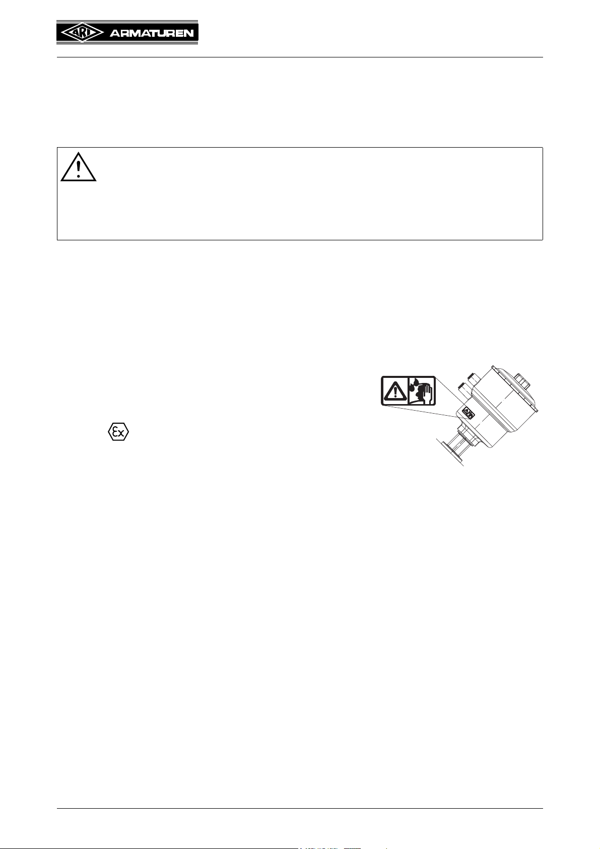
STEVI AS350 with actuator of plastic ATG:
For application of the valves in systems of device group II
category 2 acc. to Directive 94/9/EC, the valves are
equipped with a dust filter and an indicating label. The
maximum medium temperature is +85°C.
Marking: II 2 GD c IIB T6
To prevent the build up of static electricity, plastic valve
components must be wiped with a damp cloth.
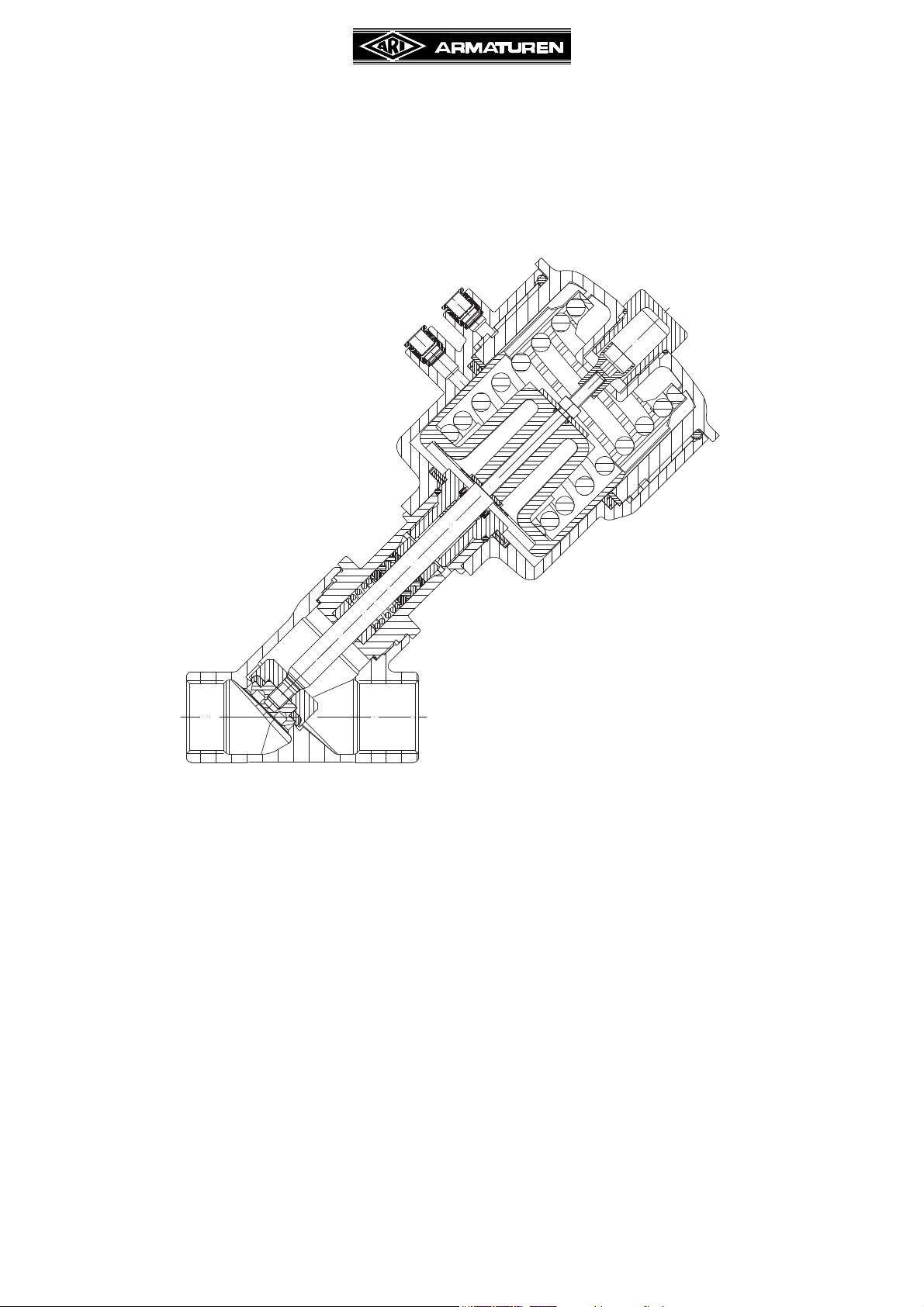
4.2 Operating principles
A Y-pattern seat in the body will be closed by a plug, depending on the flow direction with or
against the media. The plug is connected with the piston via stem. The stem is sealed
within the guidance area between the valve body and control cylinder. The valve is actuated
with a piston via control pressure (air).
Rev. 0040322000 3413 Page 2-3
Operating and installation instructions
Connection 1
Spring closes /
Air supply pressure
opens
Connection 2
Spring opens /
Air supply pressure
closes
Connection 1
Air supply pressure opens
Connection 2
Air supply pressure closes
Y-pattern processing valve - STEVI
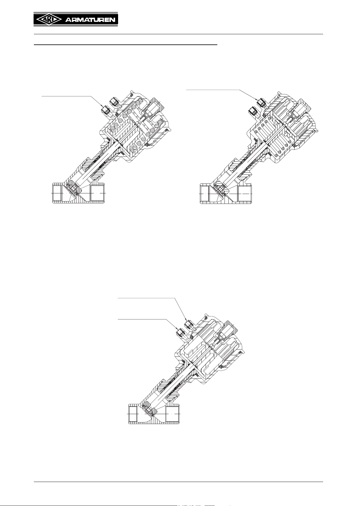
Depending on application different types are possible:
®
AS 350
1. Spring closes on air failure (NC)
Fig. 1:
When applying pressure, the air supply
pressure moves the piston against the
spring, lifts the plug from the seat and the
valve opens.
2. Spring opens on air failure (NO)
Fig. 2:
In the rest position, the valve is held by a
spring below the piston in the open position.
The valve closes by introducing the air
supply pressure.
3. Double acting (DA)
Fig. 3:
There is no sping installed in the actuator.
The valve opens and closes only by air supply pressure
Page 2-4 Rev. 0040322000 3413

4.3 Diagram
Operating and installation instructions
Y-pattern processing valve - STEVI
®
AS 350
Fig. 4: Series 350 with screwed sockets Fig. 5: Series 350 with butt weld ends
Fig. 6: Series 350 with flanges
4.4 Technical data
for
- Principal dimensions
- Pressure-temperature-ratings, etc. refer to data sheet.
Ambient temperature for the actuator: -10°C up to 60°C
Permissible control media: neutral gases, air
Max. air supply pressure: 10 bar
Rev. 0040322000 3413 Page 2-5

Operating and installation instructions
Operating pressure (bar)
Air supply pressure min. (bar)
Operating pressure (bar)
Air supply pressure min. (bar)
Manufacturer
Type
Valve data
lowest medium temperature
highest medium temperature
max. operating pressure max.
Actuator data
lowest ambient temperature
highest ambient temperature
min. air supply pressure
max. air supply pressure
Month of manufacture
Function of actuator
Year of manufacture
®
Y-pattern processing valve - STEVI
Air supply pressure
(Function: Spring closes on air failure (NC), on flow-to-open)
DN 15 20 25 32 40 50
Actuator ATG 50 ATG 50
Operating pressure max.
Kvs-value
Travel
Air supply pressure min.
(bar) 6 10 16 6 10 16 6 6 10 16 6 10 16 6 10 16 4 6 10
3
(m
/h)
(mm) 15 15 15 20 20
(bar) 2,9 4,5 6,8 2,9 4,5 6,8 5,7 2 3,1 4,8 2,8 4,3 2,8 4,3 2,8 4,5
6,2 9,6 19,7 20,7 24,8
ATG
50
ATG 80 ATG 80
Air supply pressure diagram
(Function: Spring opens on air failure (NO), on flow-to-open)
ATG
125E
25,8
25
ATG80ATG
125E
36,1
38,2
20
25
AS 350
ATG80ATG
54,3
20
5
125E
2,8
58,5
25
4,3
Fig. 7: Actuator ATG50 Fig. 8: Actuator ATG80
4.5 Marking
Fig. 9
Address of manufacturer: refer to item 11.0 Warranty / Guarantee
According to the Pressure Equipment Directive article 3, paragraph 3 (sound engineering
practice) these products need not carry a CE mark.
Page 2-6 Rev. 0040322000 3413

Operating and installation instructions
®
Y-pattern processing valve - STEVI
AS 350
5.0 Installation
5.1 General notes on installation
The following items should be taken into account besides the general principles governing
installation work:
ATTENTION !
- Remove flange covers if present.
- Remove covers from air supply connection if present.
- The interior of valve and pipeline must be free from foreign particles.
- Note installation position with reference to flow, see mark on valve.
- Steam line systems should be designed to prevent water accumulation.
- Lay pipelines so that damaging transverse, bending and torsional forces are
avoided.
- Protect valves from dirt during construction work.
- Connection flanges must mate exactly.
- Connecting bolts for pipe flanges should be mounted preferably from the
counter flange side (hexagon nuts from the valve side).
At DN15-32: If valves should be mounted directly to valves, the upper flange
connecting bolts should be preferably executed with studs and hexagon nuts on
both sides.
- Valve mountings such as actuators, handwheels, hoods must not be used to
take external forces, e.g. they are not designed for use as climbing aids, or as
connecting points for lifting gear.
- Suitable materials handling and lifting equipment should be used.
Refer to data sheet for weights.
- Centre gaskets between the flanges.
- Strainers or filters should be installed before the valves.
- Planners / construction companies or operators are responsible for positioning and
installing products.
- The valves are designed for application, not influenced from weather.
- For application outside or in adverse environments like corrosion-promoting conditions
(sea water, chemical vapours, etc.), special constructions or protective measures are
recommended.
Rev. 0040322000 3413 Page 2-7

Operating and installation instructions
®
Y-pattern processing valve - STEVI
AS 350
5.2 Requirements at the place of installation
The place of installation should be easily accessible and provide ample space for
maintenance and removing the actuator. The valve should preferably installed vertically
with the actuator at the top.
Fig. 10: Pipeline vertically Fig. 11: Pipeline horizontally
To protect the actuators from excessive heat, the pipes have to be insulated.
5.3 Installation instructions concerning actuators
Normally, stop valves are supplied complete with actuator fitted.
It is not permitted to mantle / dismantle actuators with valves operating and service
conditions (temperature and pressure). At retrofitting or maintenance, the mounting of the
bonnet has to be done acc. to item „7.1 Replacement of bonnet“.
During assembly work, the plug is not be turned on its seating at air supply pressure.
5.4 Installing valves with butt weld ends
Please note that only qualified persons using appropriate equipment and working in
accordance with technical rules are allowed to install fittings by welding.
The responsibility for this lies with the system owner.
Refer to the data sheet for information about the shape of the butt weld ends.
ATTENTION !
Before welding, the bonnet has to be dismantled in order to avoid damage
to the plug sealing.
Page 2-8 Rev. 0040322000 3413

Operating and installation instructions
ATTENTION !
Refer to item 10.0 and 11.0 before
dismantling the valve.
Y-pattern processing valve - STEVI
6.0 Putting the valve into operation
ATTENTION !
- Before putting the valve into operation, check material, pressure, temperature
and direction of flow.
- Regional safety instructions must be adhered to.
- Residues in piping and valves (dirt, weld beads, etc.) inevitably lead to leakage.
- Touching the valve when it is operating at high (> 50 °C) or low (< 0 °C) media
temperatures can cause injury.
Affix warning notice or protective insulation as appropriate!
Before putting a new plant into operation or restarting a plant after repairs or
modification, always make sure that:
- All works has been completed!
- The valve is in the correct position for its function.
- Safety devices have been attached.
- Control lines are mounted relaxed and without kinkings.
®
AS 350
7.0 Care and maintenance
Maintenance and maintenance intervals have to be defined by the operator according to
the service conditions.
7.1 Replacement of bonnet
At leakages at the stem or in the plug tightness or resp. on failures of the actuator, the
bonnet must be changed.
Fig. 12
- Relieve valve seat before removing and installing
Function:
Spring closes on air failure (NC) --> switch actuator (switch on air supply pressure);
Spring opens on air failure (NO) --> switch off air supply pressure;
Double acting (DA) --> switch off air supply pressure
- Unscrew bonnet (pos. 2) from the body (pos. 1) (at the hood above the body)
- Remove the gasket (Pos. 3) between body (Pos. 1) and bonnet (Pos. 2) from the body
(Pos. 1).
- Replace gasket (Pos. 3) and screw new bonnet (Pos. 2) into the body (Pos. 1).
(For tightening torques refer to item 7.2).
Rev. 0040322000 3413 Page 2-9

Operating and installation instructions
®
Y-pattern processing valve - STEVI
AS 350
7.2 Tightening torques
DN 15 = 50 Nm
DN 20 = 50 Nm
DN 25 = 60 Nm
DN 32 = 70 Nm
DN 40 = 80 Nm
DN 50 = 100 Nm
8.0 Troubleshooting
In the event of malfunction or faulty operating performance check that the installation and
adjustment work has been carried out and completed in accordance with these Operating
Instructions.
ATTENTION !
-
- It is essential that the safety regulations are observed when identifying faults.
If malfunctions cannot be eliminate with the help of the following table
“9.0 Troubleshooting table”, the supplier or manufacturer should be consulted.
9.0 Troubleshooting table
ATTENTION !
- read item 10.0 and 11.0 prior to dismantling and repair work!
- read item 6.0 before restarting the plant !
Fault Possible cause Corrective measures
No flow Valve closed. Open valve (using actuator).
Flange covers not removed. Remove flange covers.
Little flow Valve not sufficiently open. Open valve (using actuator).
Dirt sieve clogged. Clean / replace sieve.
Piping system clogged. Check piping system.
Valve stem moves in jerks. PTFE V-ring unit damaged or worn Replace bonnet (pos. 2);
refer to item 7.1
Leakage too high when
valve is closed.
Sealing surfaces of plug eroded or
worn.
Sealing edge of seating damages or
worn.
Seating and/or plug dirty. Clean internals of valve;
Pneumatic actuator not completely
vented; spring force not fully effective.
Actuator not powerful enough. Install more powerful actuator.
Replace bonnet (pos. 2);
refer to item 7.1
Replace valve
Vent actuator air chamber completely.
Page 2-10 Rev. 0040322000 3413

Operating and installation instructions
®
Y-pattern processing valve - STEVI
AS 350
10.0 Dismantling the valve or the top part
ATTENTION !
The following points must be observed:
- Pressureless pipe system and controle line system.
- Medium must be cool.
- Plant must be drained.
- Purge piping systems in case of caustic or aggressive media.
11.0 Warranty / Guarantee
The extent and period of warranty cover are specified in the "Standard Terms and
Conditions of Albert Richter GmbH & Co. KG“ valid at the time of delivery or, by way of
departure, in the contract of sale itself.
We guarantee freedom of faults in compliance with state-of-the-art technology and the
confirmed application.
No warranty claims can be made for any damage caused as the result of incorrect handling
or disregard of operating and installation instructions, datasheets and relavant regulations.
This warranty also does not cover any damage which occurs during operation under
conditions deviating from those laid down by specifications or other agreements.
Justified complaints will be eliminated by repair carried out by us or by a specialist
appointed by us.
No claims will be accepted beyond the scope of this warranty. The right to replacement
delivery is excluded.
The warranty shall not cover maintenance work, installation of external parts, design
modifications or natural wear.
Any damage incurred during transport should not be reported to us but rather to the
competent cargo-handling depot, the railway company or carrier company immediately or
else claims for replacements from these companies will be invalidated.
Technology for the Future.
GERMAN QUALITY VALVES
ARI-Armaturen Albert Richter GmbH & Co. KG, D-33756 Schloß Holte-Stukenbrock
Telephone (+49 5207) 994-0 Telefax (+49 5207) 994-158 or 159
Internet: http://www.ari-armaturen.com E-mail: info.vertrieb@ari-armaturen.com
Rev. 0040322000 3413 Page 2-11

Operating and installation instructions
(Brechmann, Managing director)
..............................................
®
Y-pattern processing valve - STEVI
AS 350
12.0 Manufacturers declaration
ARI-Armaturen Albert Richter GmbH & Co. KG,
Mergelheide 56-60, D-33756 Schloß Holte-Stukenbrock
EC declaration of conformity
as defined by
the Pressure Equipment Directive 97/23/EC
Herewith we declare,
that pursuant to the aforementioned Pressure Equipment Directive the products listed
below were executed and classified in accordance with Directive 97/23/EC article 3,
paragraph 3 „Sound engineering practice“ (Fluid group 2) .
Pursuant to article 3, paragraph 3 these products need not carry a CE mark.
Y-pattern processing valve
Type 350
Applied standards:
DIN 12516
AD 2000 leaflet A4
- Cast steel
Schloß Holte-Stukenbrock, 06.10.2009
Page 2-12 Rev. 0040322000 3413

Operating and installation instructions
(Brechmann, Managing director)
...................................................
Y-pattern processing valve - STEVI
13.0 EC declaration of conformity (ATEX)
EC declaration of conformity acc. to Directive 94/9/EG (ATEX)
on equipment and protective systems intended for use in potentially explosive atmospheres
Herewith we declare:
ARI-Armaturen Albert Richter GmbH & Co. KG,
Mergelheide 56-60, D-33756 Schloß Holte-Stukenbrock
that the below listed products are meeting the following requirements.
Description of the products:
®
Y-pattern processing valve ARI-STEVI
AS with actuator of plastic ATG
®
AS 350
Type
350 PN16 DN 15-50
Name and adress of the authorizing, monitoring, notified body:
TÜV NORD CERT GmbH
Langemarckstraße 20, D-45141 Essen
No. of the notified body:
0044
The appropriate operating and installation instructions contains important safety information for putting into
operation, operation and maintenance.
Schloß Holte-Stukenbrock, 21.06.2011
Nominal
pressure
Nominal
diameter
Gerätegruppe,
Kategorie, Zonen
II 2 GD c IIB T6 35083977
Depository
number
Applied
standards
EN 13463-1
EN 13463-5
DIN1127-1
Rev. 0040322000 3413 Page 2-13
 Loading...