

ARI Armaturen STEVI 462 User Manual
Operating and installation instructions
Straight through control valves - STEVI® 422 / 462
Series 422 Series 462
Contents
1.0 General information on operating
instructions .....................................................2
2.0 Notes on possible dangers............................ 2
2.1 Significance of symbols ..........................................2
2.2 Explanatory notes on safety information .................2
3.0 Storage and transport ................................... 2
4.0 Description...................................................... 3
4.1 Scope of applications ..............................................3
4.2 Operating principles ................................................3
4.3 Diagram ..................................................................4
4.3.1 Plug design ........................................................4
4.4 Technical data .........................................................5
4.5 Marking ...................................................................5
5.0 Installation....................................................... 5
5.1 General notes on installation...................................5
5.2 Requirements at the place of installation ................6
5.3 Installation instructions concerning actuators .........6
6.0 Putting the valve into operation....................7
7.0 Care and maintenance................................... 8
7.1 Replacement of stem sealings ............................... 8
7.1.1 Stuffing box packing design ............................... 8
7.1.2 Bellows seal design ........................................... 9
7.2 Replacement of internal parts ............................. 10
7.2.1 Replacement of plug and stem ....................... 10
7.2.2 Replacement of seals of
pressure balanced plugs ................................ 10
7.2.3 Replacement of the seat ring............................11
7.3 Tightening torques.................................................11
7.3.1 Tightening torques for nuts ..............................11
7.3.2 Tightening torques for seat rings .....................11
8.0 Troubleshooting ............................................11
9.0 Troubleshooting table ................................ 12
10.0 Dismantling the valve or the top part ...... 13
11.0 Warranty / Guarantee ................................. 13
12.0 EC declaration of conformity.................... 14
Rev. 0040307000 0410 englisch
Operating and installation instructions
®
Straight through control valves - STEVI
422 / 462
1.0 General information on operating instructions
These operating instructions provide information on mounting and maintaining the fittings.
Please contact the supplier or the manufacturer in case of problems which cannot be
solved by reference to the operating instructions.
They are binding on the transport, storage, installation, start-up, operation, maintenance
and repair.
The notes and warnings must be observed and adhered to.
- Handling and all work must be carried out by expert personnel or all activities must be
supervised and checked.
It is the owner’s responsibility to define areas of responsibility and competence and to
monitor the personnel.
- In addition, current regional safety requirements must be applied and observed when
taking the fittings out of service as well as when maintaining and repairing them.
The manufacturer reserves the right to introduce technical modifications at any time.
These Operating Instructions comply with the requirements of EU Directives.
2.0 Notes on possible dangers
2.1 Significance of symbols
ATTENTION !
. . .
Warning of general danger.
2.2 Explanatory notes on safety information
In these Operating and Installation Instructions dangers, risks and items of safety
information are highlighted to attract special attention.
Information marked with the above symbol and “ATTENTION ! ” describe practices, a
failure to comply with which can result in serious injury or danger of death for users or third
parties or in material damage to the system or the environment. It is vital to comply with
these practices and to monitor compliance.
All other information not specifically emphasised such as transport, installation, operating
and maintenance instructions as well as technical data (in the operating instructions,
product documentation and on the device itself) must also be complied with to the fullest
extent in order to avoid faults which in turn can cause serious injury to persons or damage
to property.
3.0 Storage and transport
ATTENTION !
- Protect against external force (like impact, vibration, etc.).
- Valve mountings such as actuators, handwheels, hoods must not be used to
take external forces, e.g. they are not designed for use as climbing aids, or as
connecting points for lifting gear.
- Suitable materials handling and lifting equipment should be used.
See catalog sheet for weights.
- At -20°C to +65°C.
- The paint is a base coat to protect against corrosion during transportation and storage. Do
not damage paint protection.
Page 2 Rev. 0040307000 0410
Operating and installation instructions
®
Straight through control valves - STEVI
422 / 462
4.0 Description
4.1 Scope of applications
Valves are used for „controlling the flow of liquids, gases and vapours in chemical and other
processing plants and for plant engineering“.
ATTENTION !
- Refer to the data sheet for applications, limits on use and possibilities.
- Certain media require or preclude the use of special materials.
- The valves are designed for standard operating conditions. If conditions exceed
these requirements, e.g. aggressive or abrasive media, the operator should
state the higher requirements when ordering.
- Valves made from grey cast iron are not authorised for use in systems subject
to TRD 110.
The information complies to the Pressure Equipment Directive 97/23/EC.
It is the responsibility of the machine planner to ensure compliance.
The special markings on the valve must be taken into account.
Refer to the catalogue sheet to see which materials are used in standard versions.
Please contact the supplier or the manufacturer if you have any questions.
4.2 Operating principles
ARI control valves are especially suitable for actuation by pneumatic or electrical actuators.
Three plug types are available to suit the various applications:
parabolic plug (standard pattern)
perforated plug
pressure balanced plug
The flow through control valves is always against the closing direction.
In the case of control valves with perforated plugs, gases and vapours flow against the
closing directions, but liquids flow through in the closing direction. If a pneumatic actuator is
to be used on a straight-way valve with a perforated plug with the fluid moving in the closing
direction, a higher closing force will be needed. This is to prevent vibration as the plug
approaches the closed position.
If the forces generated by the actuators are too low, arrangements should be made to
relieve the pressure as far as this is compatible with service conditions.
Rev. 0040307000 0410 Page 3
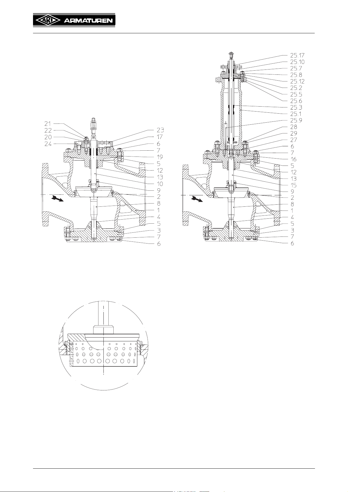
4.3 Diagram
Operating and installation instructions
Straight through control valves - STEVI
®
422 / 462
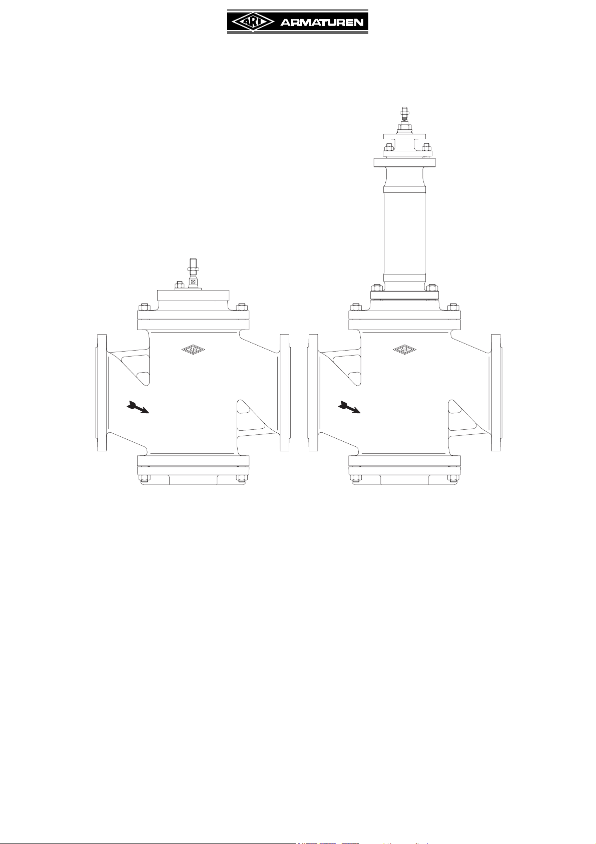
Fig. 1: Series 422 Fig. 2: Series 462
4.3.1 Plug design
Fig. 3: Perforated plug
(Pressure balanced plug
refer to Fig. 11)
Page 4 Rev. 0040307000 0410

Operating and installation instructions
Straight through control valves - STEVI
4.4 Technical data
for
- Principal dimensions
- Pressure-temperature-ratings, etc. refer to data sheet.
4.5 Marking
®
422 / 462
Kvs-value
Plug
design
Type-Number
Material of
internal parts
Nominal diameter
Flow
characteristic
Nominal pressure
Serial-No.
Year of manufacture clear speech
(1. and 2. position)
Manufacturer
CE-marking
Notified body
Customer-specific
information
Stem sealing
Fig. 4
Address of manufacturer: refer to item 11.0 Warranty / Guarantee
5.0 Installation
5.1 General notes on installation
The following items should be taken into account besides the general principles governing
installation work:
ATTENTION !
- Remove flange covers if present.
- The interior of valve and pipeline must be free from foreign particles.
- Note installation position with reference to flow, see mark on valve.
- Steam line systems should be designed to prevent water accumulation.
- Lay pipelines so that damaging transverse, bending and torsional forces are
avoided.
- Protect valves from dirt during construction work.
- Connection flanges must mate exactly.
- Connecting bolts for pipe flanges should be mounted preferably from the
counter flange side (hexagon nuts from the valve side).
- Valve mountings such as actuators, handwheels, hoods must not be used to
take external forces, e.g. they are not designed for use as climbing aids, or as
connecting points for lifting gear.
- Suitable materials handling and lifting equipment should be used.
Refer to data sheet for weights.
- Keep the thread and shaft of the stem free from paint.
- Centre gaskets between the flanges.
- Strainers or filters should be installed before the valves.
- Planners / construction companies or operators are responsible for positioning and
installing products.
- The valves are designed for application, not influenced from weather.
- For application outside or in adverse environments like corrosion-promoting conditions (sea water,
chemical vapours, etc.), special constructions or protective measures are recommended.
Rev. 0040307000 0410 Page 5
 Loading...