

ARI Armaturen STEVI 460 DN 300-500 User Manual
Operating and installation instructions
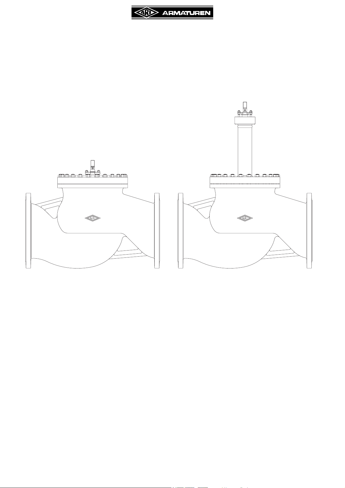
Straight through stop valves - STEVI® 405 / 460
DN 300 - 500
Series 405 Series 460
Contents
1.0 General information on operating
instructions .....................................................2
2.0 Notes on possible dangers............................ 2
2.1 Significance of symbols ..........................................2
2.2 Explanatory notes on safety information .................2
3.0 Storage and transport ................................... 2
4.0 Description...................................................... 3
4.1 Scope of applications ..............................................3
4.2 Operating principles ................................................3
4.3 Diagram ..................................................................4
4.4 Technical data .........................................................6
4.5 Marking ...................................................................6
5.0 Installation....................................................... 7
5.1 General notes on installation...................................7
5.2 Requirements at the place of installation ................8
5.3 Installation Instructions concerning actuators .........8
6.0 Putting the valve into operation....................9
7.0 Care and maintenance................................... 9
7.1 Replacement of stem sealings ............................... 9
7.1.1 EPDM-ring stem sealing design ....................... 9
7.1.2 Stuffing box packings design ........................... 10
7.1.3 Bellows seal design ..........................................11
7.2 Replacement of internal parts .............................. 12
7.2.1 Replacement of plug and stem ........................ 12
7.2.2 Replacement of the seat ring........................... 12
7.3 Tightening torques................................................ 13
7.3.1 Tightening torques for nuts ............................. 13
7.3.2 Tightening torques for seatrings ..................... 13
8.0 Troubleshooting ........................................... 13
9.0 Troubleshooting table ................................ 14
10.0 Dismantling the valve or the top part ...... 15
11.0 Warranty / Guarantee ................................. 15
12.0 EC declaration of conformity.................... 16
Rev. 0040304002 0410 englisch
Operating and installation instructions
Str. thr. stop valves - STEVI® 405 / 460 (DN300-500)
1.0 General information on operating instructions
These operating instructions provide information on mounting and maintaining the fittings.
Please contact the supplier or the manufacturer in case of problems which cannot be
solved by reference to the operating instructions.
They are binding on the transport, storage, installation, start-up, operation, maintenance
and repair.
The notes and warnings must be observed and adhered to.
- Handling and all work must be carried out by expert personnel or all activities must be
supervised and checked.
It is the owner’s responsibility to define areas of responsibility and competence and to
monitor the personnel.
- In addition, current regional safety requirements must be applied and observed when
taking the fittings out of service as well as when maintaining and repairing them.
The manufacturer reserves the right to introduce technical modifications at any time.
These Operating Instructions comply with the requirements of EU Directives.
2.0 Notes on possible dangers
2.1 Significance of symbols
ATTENTION !
. . .
Warning of general danger.
2.2 Explanatory notes on safety information
In these Operating and Installation Instructions dangers, risks and items of safety
information are highlighted to attract special attention.
Information marked with the above symbol and “ATTENTION ! ” describe practices, a
failure to comply with which can result in serious injury or danger of death for users or third
parties or in material damage to the system or the environment. It is vital to comply with
these practices and to monitor compliance.
All other information not specifically emphasised such as transport, installation, operating
and maintenance instructions as well as technical data (in the operating instructions,
product documentation and on the device itself) must also be complied with to the fullest
extent in order to avoid faults which in turn can cause serious injury to persons or damage
to property.
3.0 Storage and transport
ATTENTION !
- Protect against external force (like impact, vibration, etc.).
- Valve mountings such as actuators, handwheels, hoods must not be used to
take external forces, e.g. they are not designed for use as climbing aids, or as
connecting points for lifting gear.
- Suitable materials handling and lifting equipment should be used.
See catalog sheet for weights.
- At -20°C to +65°C.
- The paint is a base coat to protect against corrosion during transportation and storage. Do
not damage paint protection.
Page 2 Rev. 0040304002 0410

Operating and installation instructions
Str. thr. stop valves - STEVI® 405 / 460 (DN300-500)
4.0 Description
4.1 Scope of applications
Valves are used for „interrupting the flow of liquids, gases and vapours in chemical,
processing, and other plants“.
ATTENTION !
- Refer to the data sheet for applications, limits on use and possibilities.
- Certain media require or preclude the use of special materials.
- The valves are designed for standard operating conditions. If conditions exceed
these requirements, e.g. aggressive or abrasive media, the operator should
state the higher requirements when ordering.
- Valves made from grey cast iron are not authorised for use in systems subject
to TRD 110.
The information complies to the Pressure Equipment Directive 97/23/EC.
It is the responsibility of the machine planner to ensure compliance.
The special markings on the valve must be taken into account.
Refer to the catalogue sheet to see which materials are used in standard versions.
Please contact the supplier or the manufacturer if you have any questions.
4.2 Operating principles
ARI stop valves are particularly suitable for operation by pneumatic or electrical actuators.
The flow direction in these stop valves must be always opposite to the closing direction.
Rev. 0040304002 0410 Page 3
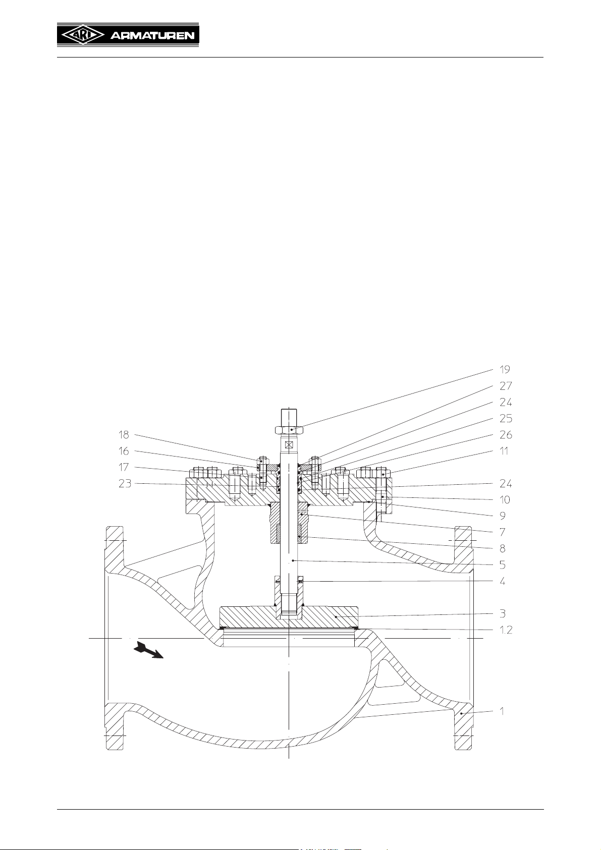
4.3 Diagram
Operating and installation instructions
Str. thr. stop valves - STEVI® 405 / 460 (DN300-500)
Fig. 1: Series 405
Page 4 Rev. 0040304002 0410
Operating and installation instructions
Str. thr. stop valves - STEVI® 405 / 460 (DN300-500)
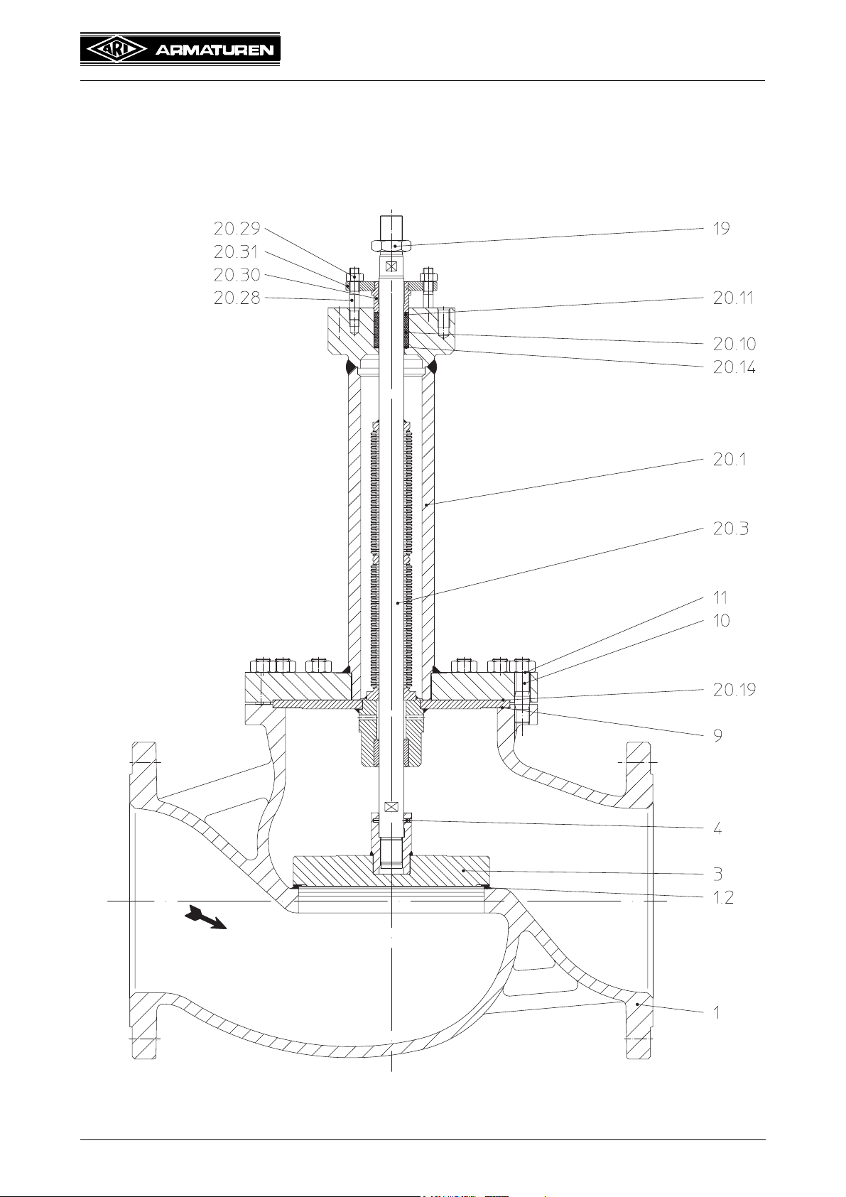
Fig. 2: Series 460
Rev. 0040304002 0410 Page 5
 Loading...