

Operating and installation instructions
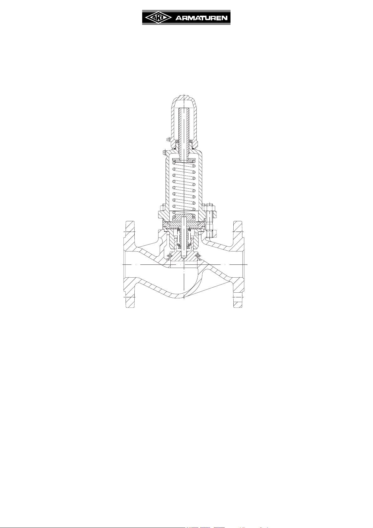
Pressure regulating valve PRESO
(spring loaded)
®
PRESO
(Series 750)
Contents
1.0 General information on operating
instructions .....................................................2
2.0 Notes on possible dangers........................... 2
2.1 Significance of symbols ..........................................2
2.2 Explanatory notes on safety information .................2
3.0 Storage and transport .................................. 3
4.0 Description.....................................................3
4.1 Scope of applications ..............................................3
4.2 Operating principles ................................................3
4.3 Diagram...................................................................4
4.4 Parts list ..................................................................4
4.5 Technical data Technical data - remarks .................5
4.6 Marking ..................................................................5
5.0 Installation......................................................6
5.1 General notes on installation...................................6
5.2 Requirements at the place of installation ................6
5.3 Strainer ...................................................................7
®
5.4 Safety valves .......................................................... 7
6.0 Putting the valve into operation .................. 7
6.1 Setting instructions ................................................ 8
6.1.1 Removing the cap ........................................... 9
6.1.2 Changing the pressure range
“without” spring change.................................... 9
6.1.3 Changing the pressure range
“with” spring change ........................................ 9
7.0 Care and maintenance................................ 10
8.0 Troubleshooting .......................................... 10
9.0 Troubleshooting table ................................11
10.0 Dismantling the valve or the top part ..... 12
11.0 Warranty / Guarantee ................................ 12
12.0 EC declaration of conformity................... 13
Rev. 0040402000 0410 englisch
Operating and installation instructions
PRESO
1.0 General information on operating instructions
These operating instructions provide information on mounting and maintaining the fittings.
Please contact the supplier or the manufacturer in case of problems which cannot be
solved by reference to the operating instructions.
They are binding on the transport, storage, installation, start-up, operation, maintenance
and repair.
The notes and warnings must be observed and adhered to.
- Handling and all work must be carried out by expert personnel or all activities must be
supervised and checked.
It is the owner’s responsibility to define areas of responsibility and competence and to
monitor the personnel.
- In addition, current regional safety requirements must be applied and observed when
taking the fittings out of service as well as when maintaining and repairing them.
The manufacturer reserves the right to introduce technical modifications at any time.
These Operating Instructions comply with the requirements of EU Directives.
®
2.0 Notes on possible dangers
2.1 Significance of symbols
ATTENTION !
. . .
2.2 Explanatory notes on safety information
In these Operating and Installation Instructions dangers, risks and items of safety
information are highlighted to attract special attention.
Information marked with the above symbol and “ATTENTION!” describe practices, a failure
to comply with which can result in serious injury or danger of death for users or third parties
or in material damage to the system or the environment. It is vital to comply with these
practices and to monitor compliance.
All other information not specifically emphasised such as transport, installation, operating
and maintenance instructions as well as technical data (in the operating instructions,
product documentation and on the device itself) must also be complied with to the fullest
extent in order to avoid faults which in turn can cause serious injury to persons or damage
to property.
Warning of general danger.
Non-compliance with operating instructions is dangerous!
Read the operating instructions before installation, operation,
maintenance or disassembly and adhere to them strictly.
Page 2 Rev. 0040402000 0410
Operating and installation instructions
PRESO
®
3.0 Storage and transport
ATTENTION !
- Protect against external force (like impact, vibration, etc.).
- Valve mountings such as actuators, handwheels, hoods must not be used to
take external forces, e.g. they are not designed for use as climbing aids, or as
connecting points for lifting gear.
- Suitable materials handling and lifting equipment should be used.
See catalog sheet for weights.
- At -20°C to +65°C.
- The paint is a base coat to protect against corrosion during transportation and storage. Do
not damage paint protection.
4.0 Description
4.1 Scope of applications
Pressure regulating valves are used for „passing excess media in pressure systems“.
The valve has no safety function.
ATTENTION !
- Refer to the data sheet for applications, limits on use and possibilities.
- Certain media require or preclude the use of special materials.
- The valves are designed for standard operating conditions. If conditions exceed
these requirements, e.g. aggressive or abrasive media, the operator should
state the higher requirements when ordering.
- Valves made from grey cast iron are not authorised for use in systems subject
to TRD 110.
The information complies to the Pressure Equipment Directive 97/23/EC.
It is the responsibility of the machine planner to ensure compliance.
The special markings on the valve must be taken into account.
Refer to the catalogue sheet to see which materials are used in standard versions.
Please contact the supplier or the manufacturer if you have any questions.
4.2 Operating principles
A pressure regulating valve is a valve where a preset pressure or a differential pressure is
adjusted an the valve opens and closes automatically.
The over flow function is regulated through a spring.
Rev. 0040402000 0410 Page 3
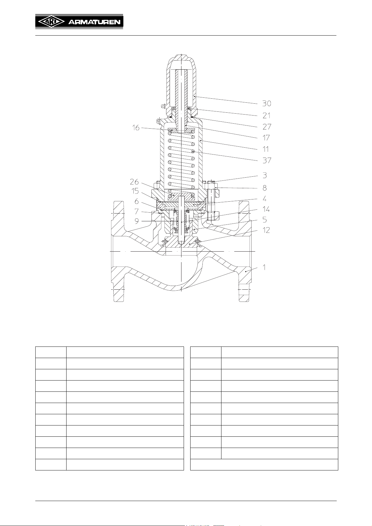
4.3 Diagram
Operating and installation instructions
PRESO
®
Fig. 753
Fig. 1
4.4 Parts list
Pos Description Pos Description
1 Body 14 Spindle unit
3 Stud 15 Gasket
4 Guide plate 16 Spring plate (top)
5 Guide bush 17 Adjusting screw
6 Gasket 21 Lock nut
7 Gasket 26 Spring plate (bottom)
8 Hex. nut 27 Gasket
9 Travel limiter ring 30 Cap
11 Bonnet 37 Spring
12 Disc unit
Refer to the data sheet for information about materials with designations and figure
numbers.
Page 4 Rev. 0040402000 0410

Operating and installation instructions
PRESO
4.5 Technical data Technical data - remarks
for
- Principal dimensions
- Pressure-temperature-ratings, etc. refer to datasheet.
Nominal diameter: DN 15 - DN 100 / 1/2“- 4“
Nominal pressure: PN 6, PN 10, PN 16, ANSI 150
Body material: EN-JL1040, EN-JS1049, 1.0619+N, SA 216 WCB, 1.4408
Pressure ranges: 0,5 - 1,5 bar; 1,0 - 3,0 bar; 2,0 - 5,0 bar; 4,0 - 10,0 bar
Temperature: acc. to Pressure-temperature-classification, refer to data sheet
Disc sealing: Metal
Spindle sealing: Stainless steel bellow
4.6 Marking
®
Figure-No. /
Type-No.
Year of manufacture
(clear speech)
(1. and 2. position)
Manufacturer
Serial-No.
max. permissible
operating temperature /
operating pressure
CE-marking
Kvs-value
Range
Notified body
Fig. 2
Address of manufacturer: refer to item 11.0 Warranty / Guarantee
According to the Pressure Equipment Directive table 6, annex II valves without safety
function are only allowed to bear the CE-marking DN32 onwards.
Rev. 0040402000 0410 Page 5

Operating and installation instructions
PRESO
®
5.0 Installation
5.1 General notes on installation
The following points should be taken into account besides the general principles governing
installation work:
ATTENTION !
- Remove flange covers if present.
- The interior of valve and pipeline must be free from foreign particles.
- Note installation position with reference to flow, see mark on valve.
- Steam line systems should be designed to prevent water accumulation.
- Lay pipelines so that damaging transverse, bending and torsional forces are
avoided.
- Protect valves from dirt during construction work.
- Connection flanges must mate exactly.
- Connecting bolts for pipe flanges should be mounted preferably from the
counter flange side (hexagon nuts from the valve side).
At DN15-32: If valves should be mounted directly to valves, the upper flange
connecting bolts should be preferably executed with studs and hexagon nuts on
both sides.
- Valve mountings such as actuators, handwheels, hoods must not be used to
take external forces, e.g. they are not designed for use as climbing aids, or as
connecting points for lifting gear.
- Suitable materials handling and lifting equipment should be used.
See catalog sheet for weights.
- Freezing, sticking or blocking of the surplus valve must be avoided at all costs
(e.g. by heating).
- Before adjusting, remove the cap carefully.
Media could emerge which has accumulated (only with broken bellow!)
- Pressure regulating valves don’t have any safety function.
- Planners / construction companies or operators are responsible for positioning and
installing products.
- The valves are designed for application, not influenced from weather.
- For application outside or in adverse environments like corrosion-promoting conditions
(sea water, chemical vapours, etc.), special constructions or protective measures are
recommended.
- Clean and flush the plant before it is put into operation as dirty media can cause damage
to disc and seat.
- Centre gaskets between the flanges.
- The pressure regulating valves shall be installed with upright bonnet.
5.2 Requirements at the place of installation
The place of installation should be easily accessible and provide ample space for
maintenance and removing the cap. Stopvalves should be installed before and after the
pressure regulating valve to enable maintenance working without draining the piping
system. With the installation of a bypass line the system can run on manually.
Install manometers to control the up- and downstream pressures.
When isolating the system the cap must stay free.
Page 6 Rev. 0040402000 0410

5.3 Strainer
ATTENTION !
Operating and installation instructions
PRESO
®
-
A strainer should be installed in a suitable position.
The strainer must be cleaned from time to time.
5.4 Safety valves
ATTENTION !
-
The system must be protected against excess pressure. The necessary safety
valve must be dimensioned so that the max. possible massflow can be blown of
by the safety valve.
The set pressure depends on the system part with the lowest pressure burden,
and there must be a sufficiently large gap between set pressure and system
pressure.
If necessary the upstream pressure (P1) and the pressure downstream of the
surplus valve (P2) should be equipped with a safety valve.
6.0 Putting the valve into operation
ATTENTION !
- Before putting the valve into operation, check material, pressure, temperature
and direction of flow.
- Regional safety instructions must be adhered to.
- Residues in piping and valves (dirt, weld beads, etc.) inevitably lead to leakage.
- Touching the valve when it is operating at high (> 50°C) or low (< 0°C) media
temperatures can cause injury.
Affix warning notice or protective insulation as appropriate!
- Pressure regulating valves don’t have any safety function.
- Always make sure that the pressure regulating valve cannot freeze or become
clogged or blocked (e.g. through heating)
Before putting a new plant into operation or restarting a plant after repairs or
modification, always make sure that:
- All works has been completed!
- The valve is in the correct position for its function.
- Safety devices have been attached.
Rev. 0040402000 0410 Page 7

Operating and installation instructions
PRESO
Start-up then takes place as follows:
- Carefully open stop valves upstream and downstream of surplus valve.
- Dismantle cap (see point 6.1.1).
- Adjust tensioning screw (see point 6.1.2) until the desired differential pressure ΔP
is reached.
e.g. Setting at 2 bar
Back pressure 0.5 bar ΔP = 1.5 bar
The surplus valve generally removes the required amount of flow, with a
corresponding pressure increase by way of the set pressure.
The statement of Kv value on the type identification plate corresponds to
ΔP + 50% pressure increase.
e.g. ΔP at setting x 1.5 ΔP + 50% = 2.25 bar ΔP
6.1 Setting instructions
®
Stem (assembly aid)
Fig. 3
Page 8 Rev. 0040402000 0410

Operating and installation instructions
PRESO
6.1.1 Removing the cap
ATTENTION !
By alterations, media could emerge out of the adjusting screw
(only with broken bellow)!
- Unscrew cap (pos. 30), pay attention for media emerging from the valve.
6.1.2 Changing the pressure range “without” spring change
- Check the spring range.
- Loosen lock nut (pos. 21).
- Turn adjusting screw (pos. 17) clockwise to increase and anticlockwise to reduce the
pressure range (alterations only by flowing media).
- Secure spring setting by tightening lock nut (pos. 21).
- Assemble cap.
®
6.1.3 Changing the pressure range “with” spring change
ATTENTION !
Before dismantling, the system must be made pressureless! (refer to point 10.0)
- Loosen locknut (pos. 21), turn adjusting screw (pos. 17) anticlockwise to reduce the spring
(pos. 37) force.
- Unscrew nuts (pos. 8) at flange connection and remove bonnet (pos. 11).
ATTENTION !
At relatively high pressures the nuts (pos. 8) on the two longer stud bolts (pos. 3)
must be removed last and simultaneously!
- Remove upper spring plate (pos. 16) and spring (pos. 37).
- Replace new spring (pos. 37) and upper spring plate (pos. 16).
- Change gaskets.
- Mount bonnet (pos. 11) with the help of a rod (refer to Fig. 3 ), the upper spring plate
(pos. 16) and spring (pos. 37) is centered to the adjusting screw (pos. 17). Then reset the
pressure range with flowing media, refer to spring range (refer to point 6.0 Putting the
valve into operation).
- Secure spring setting by tightening lock nut (pos. 21).
- Assemble cap.
ATTENTION !
- Torques must be observed:
M10 16 - 25 Nm
M12 30 - 40 Nm
M16 70 - 90 Nm
Rev. 0040402000 0410 Page 9

Operating and installation instructions
PRESO
7.0 Care and maintenance
Maintanance and maintenance-intervals have to be defined by the operator according to
the requirements.
- Leakage caused through damage to disc and seat must be repaired through us or an
authorised work shop.
- Our setting instructions (point 6.0) must be strictly adhered to when alterations to setting
or spring changes are made.
8.0 Troubleshooting
In the event of malfunction or faulty operating performance check that the installation and
adjustment work has been carried out and completed in accordance with these Operating
Instructions.
ATTENTION !
®
-
It is essential that the safety regulations are observed when identifying faults.
If malfunctions cannot be eliminate with the help of the following table
“9.0 troubleshooting table”, the supplier or manufacturer should be consulted.
Page 10 Rev. 0040402000 0410

Operating and installation instructions
9.0 Troubleshooting table
ATTENTION !
- read point 10.0 and 11.0 prior to dismantling and repair work!
- read point 6.0 before restarting the plant !
Fault Possible cause Corrective measures
No flow Flange covers not removed Remove flange covers
Little flow Dirt sieve clogged Clean / replace sieve
Piping system clogged Check piping system
PRESO
®
Pressure regulating valve
does not respond, no flow
Pressure regulating valve
seat leaking
Flange broken Damage during transport Replace pressure regulating valve
Pressure regulating valve
constantly open
Flattering Pressure regulating valve capacity too
Pressure range too high Reset (point 6.0) or replace the
pressure regulating valve
Stainless steel bellow defective Replace pressure regulating valve
Medium viscous or sticky Use heating jacket
The valves and piping must be
protected against freezing and
solidifying media
Valve installed against flow direction Turn the valve into flow direction
Pressure regulating valve flattering Refer to separate point “Flattering”
Medium contaminated; foreign body
between seat and disc
Flange bolts not evenly tightened Replace pressure regulating valve
Transfer of unacceptable forces, e.g.
bending or torsional forces
Spring corroded by medium and broken Replace pressure regulating valve
Spindle guide corroded
high
Use heating jacket !
Replace pressure regulating valve
Install free of tension
Install smaller pressure regulating
valve
Capacity too low Pressure regulating valve not applied
unsuitable for plant conditions
Rev. 0040402000 0410 Page 11
Select and install suitable pressure
regulating valve

Operating and installation instructions
PRESO
10.0 Dismantling the valve or the top part
ATTENTION !
The following points must be observed:
- Pressureless pipe system.
- Medium must be cool.
- Plant must be drained.
- Purge piping systems in case of caustic, inflammable, aggressive or toxic
media.
11.0 Warranty / Guarantee
The extent and period of warranty cover are specified in the "Standard Terms and
Conditions of Albert Richter GmbH & Co. KG" valid at the time of delivery or, by way of
departure, in the contract of sale itself.
We guarantee freedom of faults in compliance with state-of-the-art technology and the
confirmed application.
®
No warranty claims can be made for any damage caused as the result of incorrect handling
or disregard of operating and installation instructions, datasheets and relavant regulations.
This warranty also does not cover any damage which occurs during operation under
conditions deviating from those laid down by specifications or other agreements.
Justified complaints will be eliminated by repair carried out by us or by a specialist
appointed by us.
No claims will be accepted beyond the scope of this warranty. The right to replacement
delivery is excluded.
The warranty shall not cover maintenance work, installation of external parts, design
modifications or natural wear.
Any damage incurred during transport should not be reported to us but rather to the
competent cargo-handling depot, the railway company or carrier company immediately or
else claims for replacements from these companies will be invalidated.
Technology for the Future.
GERMAN QUALITY VALVES
ARI-Armaturen Albert Richter GmbH & Co. KG, D-33756 Schloß Holte-Stukenbrock
Telephone (+49 5207) 994-0 Telefax (+49 5207) 994-158 or 159
Internet: http://www.ari-armaturen.com E-mail: info.vertrieb@ari-armaturen.com
Page 12 Rev. 0040402000 0410

Operating and installation instructions
PRESO
®
12.0 EC declaration of conformity
ARI-Armaturen Albert Richter GmbH & Co. KG,
Mergelheide 56-60, 33756 Schloß Holte-Stukenbrock
EC declaration of conformity
as defined by
the Pressure Equipment Directive 97/23/EC and
Herewith we declare,
that according to the above mentioned Pressure Equipment Directive (PED) the below listed
products comply and have been approved according to table 6, annex II, Module H through Lloyd´s
Register Quality Assurance GmbH (BS-No. 0525), Am Sandtorkai 41, D-20457 Hamburg.
Certificate-No: 50003/1
Pressure regulating valve
PRESO
®
Type 753
Applied standards:
DIN 3230
DIN 3840
AD 2000 leaflet A4
- Cast iron with spheroidal graphite
- Cast steel
- Forged steel
Schloß Holte-Stukenbrock, 11.01.2010
...................................................
(Brechmann, Managing director)
Rev. 0040402000 0410 Page 13
 Loading...