

ARI Armaturen PREDU 700 User Manual
Operating and installation instructions
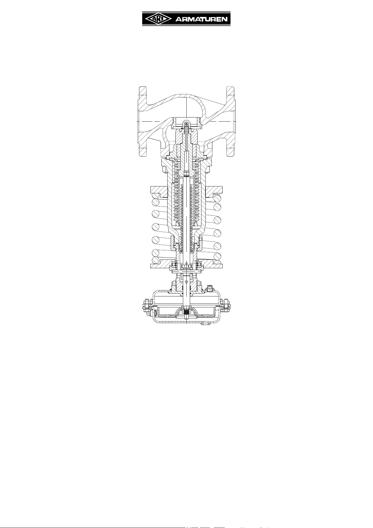
Pressure reducing valve PREDU
PREDU
(Series 700)
®
®
Contents
1.0 General information on operating instructions2-2
2.0 Notes on possible dangers ............................... 2-2
2.1 Significance of symbols ...................................... 2-2
2.2 Explanatory notes on safety information ............. 2-2
3.0 Storage and transport ....................................... 2-3
4.0 Description ......................................................... 2-3
4.1 Scope of applications .......................................... 2-3
4.2 Operating principles ............................................ 2-4
4.3 Diagram .............................................................. 2-5
4.3.1 Parts ........................................................ 2-5
4.4 Technical data - remarks ..................................... 2-6
4.5 Marking .............................................................. 2-7
4.5.1 Marking of special flanges ....................... 2-8
5.0 Installation .......................................................... 2-9
5.1 General notes on installation............................... 2-9
5.2 Requirements at the place of installation .......... 2-10
5.3 Installation instructions concerning actuators ... 2-10
5.4 Control line, flow restrictor, water seal pot .........2-11
Rev. 0040701000 1714 englisch Page 2-1
5.5 System arrangement - pressure reducing
station................................................................ 2-12
5.6 Strainer ............................................................. 2-13
5.7 Safety valves ..................................................... 2-13
6.0 Putting the valve into operation...................... 2-13
7.0 Care and maintenance ..................................... 2-14
8.0 Troubleshooting ............................................... 2-14
9.0 Troubleshooting table .................................... 2-15
10.0 Dismantling the valve or the top part .......... 2-17
11.0 Warranty / Guarantee ..................................... 2-17
Operating and installation instructions
PREDU
1.0 General information on operating instructions
These operating instructions provide information on mounting and maintaining the fittings.
Please contact the supplier or the manufacturer in case of problems which cannot be
solved by reference to the operating instructions.
They are binding on the transport, storage, installation, start-up, operation, maintenance
and repair.
The notes and warnings must be observed and adhered to.
- Handling and all work must be carried out by expert personnel or all activities must be
supervised and checked.
It is the owner’s responsibility to define areas of responsibility and competence and to
monitor the personnel.
- In addition, current regional safety requirements must be applied and observed when
taking the fittings out of service as well as when maintaining and repairing them.
The manufacturer reserves the right to introduce technical modifications at any time.
These Operating Instructions comply with the requirements of EU Directives.
®
2.0 Notes on possible dangers
2.1 Significance of symbols
ATTENTION !
. . .
2.2 Explanatory notes on safety information
In these Operating and Installation Instructions dangers, risks and items of safety
information are highlighted to attract special attention.
Information marked with the above symbol and “ATTENTION!” describe practices, a failure
to comply with which can result in serious injury or danger of death for users or third parties
or in material damage to the system or the environment. It is vital to comply with these
practices and to monitor compliance.
All other information not specifically emphasised such as transport, installation, operating
and maintenance instructions as well as technical data (in the operating instructions,
product documentation and on the device itself) must also be complied with to the fullest
extent in order to avoid faults which in turn can cause serious injury to persons or damage
to property.
Warning of general danger.
Non-compliance with operating instructions is dangerous!
Read the operating instructions before installation, operation,
maintenance or disassembly and adhere to them strictly.
Page 2-2 Rev. 0040701000 1714
Operating and installation instructions
PREDU
®
3.0 Storage and transport
ATTENTION !
- Protect against external force (like impact, vibration, etc.).
- Valve mountings such as actuators, handwheels, hoods must not be used to
take external forces, e.g. they are not designed for use as climbing aids, or as
connecting points for lifting gear.
- Suitable materials handling and lifting equipment should be used.
See catalog sheet for weights.
- At -20°C to +65°C.
- The paint is a base coat to protect against corrosion during transportation and storage. Do
not damage paint protection.
4.0 Description
4.1 Scope of applications
Pressure reducing valves are used for „pressure regulation of liquids, steam, gases and
vapours in the procedure and process technic as well as in the plant manufacture“.
ATTENTION !
- Refer to the data sheet for applications, limits on use and possibilities.
- The pressure reducing valve is suitable for regulation of fluids of group II acc. to
Pressure Equipment Directive 97/23/EC.
- Certain media require or preclude the use of special materials.
- The valves are designed for standard operating conditions. If conditions exceed
these requirements, e.g. aggressive or abrasive media, the operator should
state the higher requirements when ordering.
- Valves made from grey cast iron are not authorised for use in systems subject
to TRD 110.
The information complies to the Pressure Equipment Directive 97/23/EC.
It is the responsibility of the machine planner to ensure compliance.
The special markings on the valve must be taken into account.
Refer to the catalogue sheet to see which materials are used in standard versions.
Please contact the supplier or the manufacturer if you have any questions.
Rev. 0040701000 1714 Page 2-3

Operating and installation instructions
PREDU
®
4.2 Operating principles
The pressure reducing valve is a direct acting proportional regulator for regulating the
pressure of fluid, gas and vapour media of Fluid Group II pursuant to Pressure Equipment
Directive 97/23/EC. No auxiliary energy is needed.
In a pressureless state the valve is fully open. The media passes through the valve from the
inlet to the outlet. The downstream pressure sensing point should be positioned at least
10 x DN or a minimum of 1 m away from the valve, and is passed on to the actuator over
the control line pipe (refer to Fig. 5).
For operating temperatures above the allowable actuator temperature (refer to points 4.4
and 5.4) a water seal pot must be installed. The whole system, water seal pot, control line
and actuator must be filled with liquid (by steam with water). The downstream pressure is
converted over the actuator diaphragm in a force working in the disc closing direction.
The spring force is attained in the spindle over a pin and coupling and is opposed through
the diaphragm force, therefore works in the disc open direction. When both forces are
equal, the valve is balanced, and the downstream pressure is maintained constant.
When the downstream pressure is altered the disc either „opens“ or „closes“.
Page 2-4 Rev. 0040701000 1714
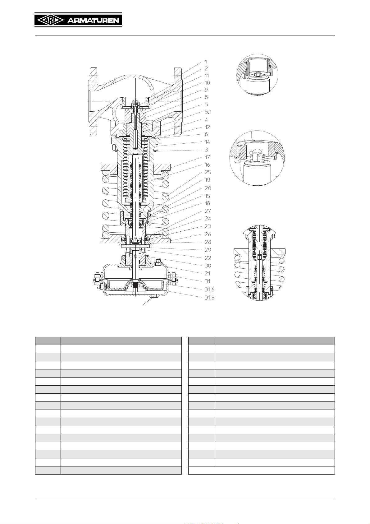
4.3 Diagram
Control line connection
Plug DN 15 - 32
Bellows DN 15 - 40
Plug DN 40 - 150
Operating and installation instructions
PREDU
®
Fig. 1
4.3.1 Parts
Pos. Designation Pos. Designation
1 Body 19 Screw
2 Screwed seat 20 Thread pin
3 Stud 21 Guide bush
4 Gasket 22 Guide coupling
5 Bush housing 23 Cylindrical balls
5.1 Guide bush 24 Securing wire
6 Gasket 25 Spring
8 Balanced bellows unit 26 Spring plate
9 Plug unit 27 Axial bearing
11 Head 28 Pressure plate
12 Bonnet closed 29 Pin
14 Hexagon nut 30 Lock nut
15 Gasket 31 DMA-Pneumatic actuator
16 Sealing bellows unit 31.6 Rolling diaphragm
17 Adjusting plate 31.8 Collar nut
18 Head
Refer to the data sheet for information about materials with designations and figure
numbers.
Rev. 0040701000 1714 Page 2-5

Operating and installation instructions
PREDU
4.4 Technical data - remarks
for
- Principal dimensions
- Pressure-temperature-ratings, etc. refer to datasheet.
Nominal diameter: DN 15 - DN 150, 1“ - 6“
Pressure class: PN 16, PN 25, PN 40, ANSI 150, ANSI 300
Body material: EN-JL1040, EN-JS1049, 1.0619+N, SA216WCB
Actuator size: DMA 40, 80, 160, 250, 400 - NBR, EPDM
Downstream pressure: acc. to downstream pressure table min. 0,2 bar, max. 16 bar
Temperature - valve: acc. to pressure-temperature table refer to datasheet
Temperature - actuator: max. 100C (NBR-diaphragm)
max. 130C (EPDM-diaphragm)
®
Disc seal: Metal, PTFE soft seal
Spindle tightness: Stainless steel bellows
Page 2-6 Rev. 0040701000 1714
 Loading...