

ARI Armaturen DP34 User Manual
Operating and installation instructions
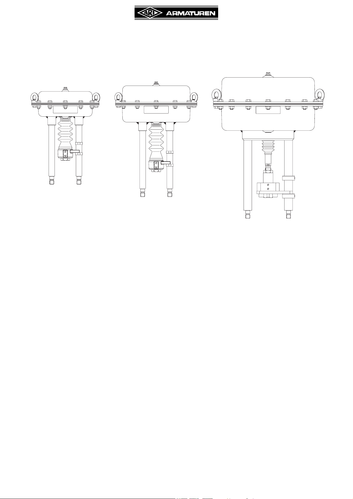
Pneumatic actuators - DP32 / DP33 / DP34
DP32
DP33 DP34
Contents
1.0 General information on operating instructions....2
2.0 Notes on possible dangers ....................................2
2.1 Significance of symbols ........................................2
2.2 Explanatory notes on safety information ...............2
3.0 Storage and transport ............................................3
4.0 Description ..............................................................3
4.1 Scope of applications ............................................3
4.2 Operating principles ..............................................3
4.3 Diagram.................................................................4
4.4 Technical data .....................................................10
4.5 Marking ............................................................... 11
5.0 Installation .............................................................11
5.1 General notes on installation...............................11
5.2 Requirements at the place of installation ............12
5.3 Valve with actuator..............................................13
5.4 Control pressure connection ...............................15
5.5 Assembling the valve, operating mode
„actuator stem extends by spring force“ ..............15
5.6 Setting the starting point, operating mode
„actuator stem extends by spring force“ ..............16
5.7 Assembling the valve, operating mode
„actuator stem retracts by spring force“...............16
5.8 Setting the starting point, operating mode
„actuator stem retracts by spring force“...............17
6.0 Putting the valve into operation ..........................17
7.0 Disassembly of the actuator unit
from the valve ....................................................... 18
7.1 Disassembly of the actuator unit ........................ 18
8.0 Care and maintenance ......................................... 19
8.1 Replacing the rolling diaphragm......................... 19
8.2 Replacing the guiding band and the o-ring......... 21
9.0 Alterations............................................................. 21
9.1 Replacing the spring set..................................... 21
9.1.1 Replacement by operation mode
"actuator stem extends by spring force" ........... 21
9.1.2 Replacement by operation mode
"actuator stem retracts by spring force" ............ 22
9.2 Change of operating mode................................. 23
9.2.1 Change of operating mode "actuator stem
extends by spring force" in "actuator stem
retracts by spring force" .................................... 23
9.2.2 Change of operating mode "actuator stem
retracts by spring force" in "actuator stem
extends by spring force" ................................... 24
10.0 Troubleshooting ................................................. 27
11.0 Troubleshooting table ....................................... 27
12.0 Warranty / Guarantee ......................................... 28
Rev. 0040504000 1210 englisch
Operating and installation instructions
Pneumatic actuators - DP32 / DP33 / DP34
1.0 General information on operating instructions
These operating instructions provide information on mounting and maintaining the fittings.
Please contact the supplier or the manufacturer in case of problems which cannot be
solved by reference to the operating instructions.
They are binding on the transport, storage, installation, start-up, operation, maintenance
and repair.
The notes and warnings must be observed and adhered to.
- Handling and all work must be carried out by expert personnel or all activities must be
supervised and checked.
It is the owner’s responsibility to define areas of responsibility and competence and to
monitor the personnel.
- In addition, current regional safety requirements must be applied and observed when
taking the fittings out of service as well as when maintaining and repairing them.
The manufacturer reserves the right to introduce technical modifications at any time.
These Operating Instructions comply with the requirements of EU Directives.
2.0 Notes on possible dangers
2.1 Significance of symbols
ATTENTION !
. . .
2.2 Explanatory notes on safety information
In these Operating and Installation Instructions dangers, risks and items of safety
information are highlighted to attract special attention.
Information marked with the above symbol and “ATTE N TIO N ! ” describe practices, a
failure to comply with which can result in serious injury or danger of death for users or third
parties or in material damage to the system or the environment. It is vital to comply with
these practices and to monitor compliance.
All other information not specifically emphasised such as transport, installation, operating
and maintenance instructions as well as technical data (in the operating instructions,
product documentation and on the device itself) must also be complied with to the fullest
extent in order to avoid faults which in turn can cause serious injury to persons or damage
to property.
Warning of general danger.
Exposed to injury!
Don‘t put your hand into the up or downwards moving
appliance.
Page 2 0040504000 1210

Operating and installation instructions
Pneumatic actuators - DP32 / DP33 / DP34
3.0 Storage and transport
ATTENTION !
- Protect against external force (like impact, vibration, etc.).
- Valve mountings such as actuators, handwheels, hoods must not be used to
take external forces, e.g. they are not designed for use as climbing aids, or as
connecting points for lifting gear.
- Suitable materials handling and lifting equipment
should be used.
Observe max. load-carrying capacity of the eye
nuts: DP32/33 = 100kg, DP34 =170kg
(Refer to catalog sheet for weights)
- At -20°C to +65°C.
- Do not damage paint protection. (The actuators should rest in the packing till installation.)
4.0 Description
4.1 Scope of applications
The pneumatic actuators are to be mounted on the top of valves and are necessary to
operate the valves (stem movement) under service conditions.
The units are suitable for being employed in control systems used in the chemical industry.
ATTENTION !
- Refer to the data sheet for applications, limits on use and possibilities.
Please contact the supplier or the manufacturer if you have any questions.
4.2 Operating principles
By means of the pneumatic actuator units, pneumatic control signals are converted into a
translatory motion. The necessary restoring force is generated by means of the
compression springs on the bulk of the diaphragm plate.
In case of air fall-off, the actuator will be restored by means of the spring force in the
starting position.
The operating mode of the actuator is the following:
„actuator stem extends by spring force“ (on air failure) or
„actuator stem retracts by spring force“ (on air failure)
This operation is obtained and dependent on the assembly of the springs.
By using a rolling diaphragm, linear rod forces during long lifts can be obtained.
The pneumatic actuators with manual emergency adjustment can be operated without
operating pressure by turning the handwheel.
In case of usual operating the handwheel is locked by a locking device. This prevents the
handwheel from turning. To engage the handwheel, the locking device must first be pulled
out.
ATTENTION !
- After engaging, the manual emergency adjustment has to be set in starting
position to avoid the deadlock with usual operating.
0040504000 1210 Page 3

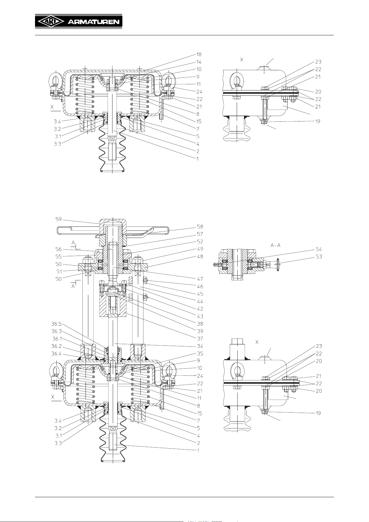
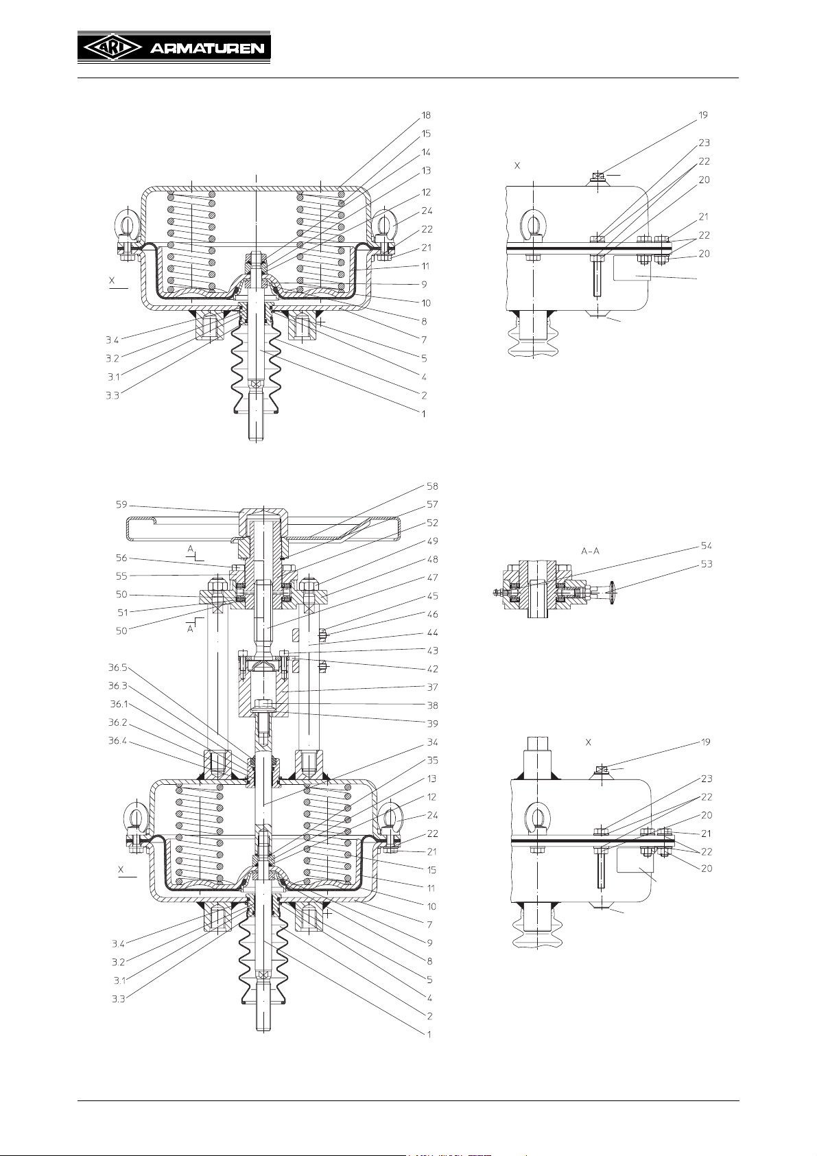
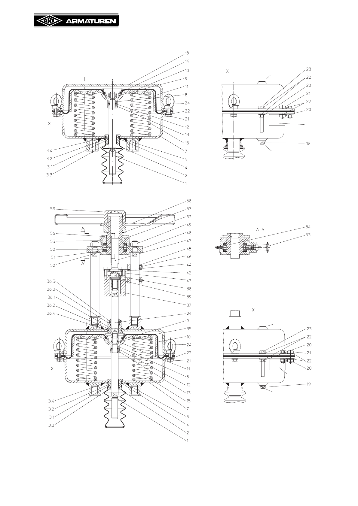
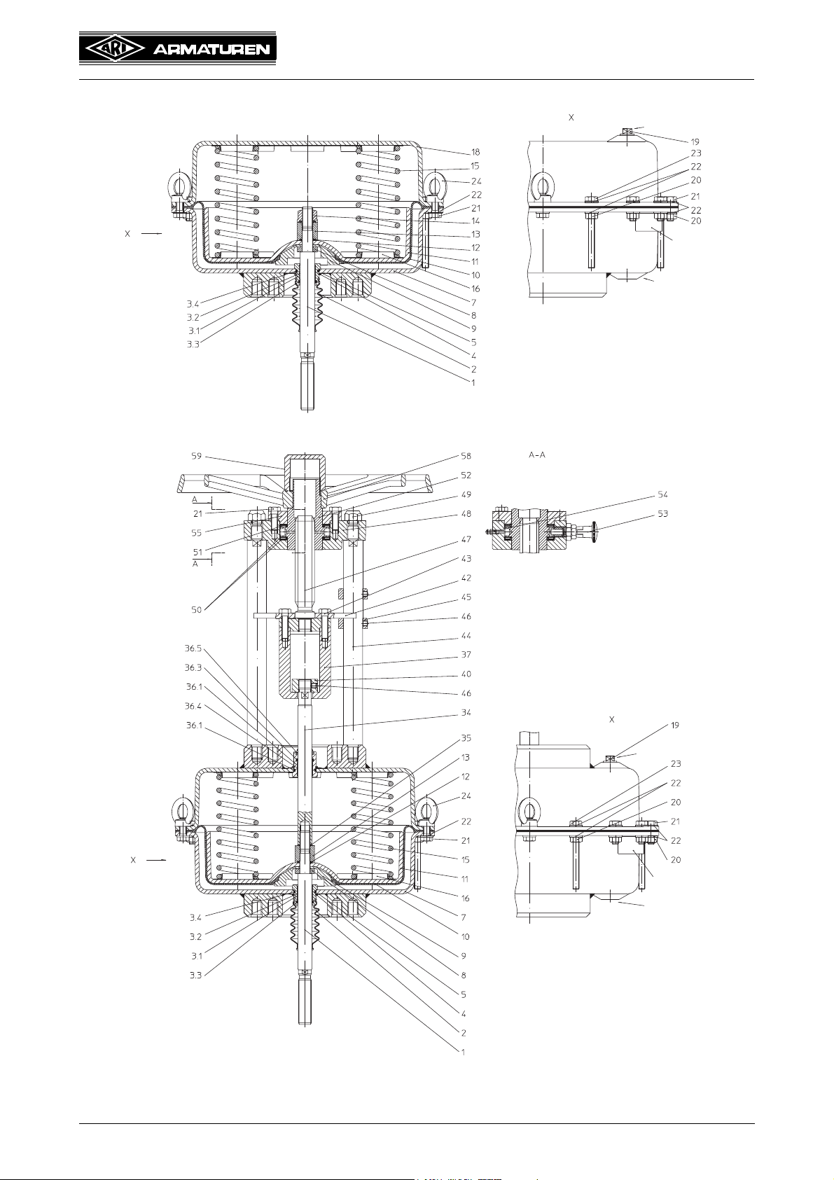
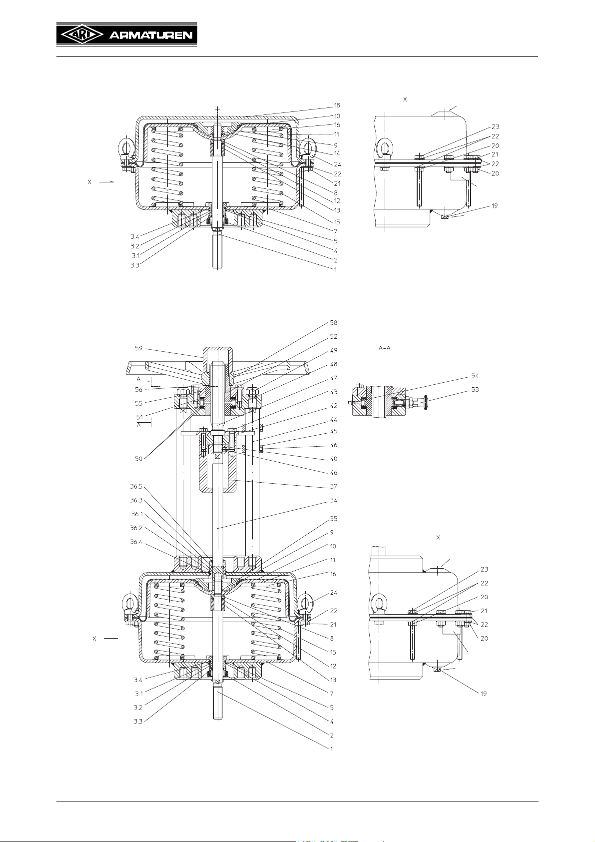
4.3 Diagram
Operating and installation instructions
Pneumatic actuators - DP32 / DP33 / DP34
Ventilation
Fig. 1: DP32 „actuator stem extends by spring force“
Air connection
Name plate
Ventilation
Name plate
Air connection
Fig. 2: DP32 with manual emergency adjustment „actuator stem extends by spring force“
Page 4 0040504000 1210
Operating and installation instructions
Pneumatic actuators - DP32 / DP33 / DP34
Fig. 3: DP32 „actuator stem retracts by spring force“
Air connection
Name plate
Ventilation
Air connection
Name plate
Ventilation
Fig. 4: DP32 with manual emergency adjustment „actuator stem retracts by spring force“
0040504000 1210 Page 5
Operating and installation instructions
Pneumatic actuators - DP32 / DP33 / DP34
Ventilation
Name plate
Air connection
Fig. 5: DP33 „actuator stem extends by spring force“
Ventilation
Name plate
Air connection
Fig. 6: DP33 with manual emergency adjustment „actuator stem extends by spring force“
Page 6 0040504000 1210
Operating and installation instructions
Pneumatic actuators - DP32 / DP33 / DP34
Air connection
Name plate
Ventilation
Fig. 7: DP33 „actuator stem retracts by spring force“
Air connection
Name plate
Ventilation
Fig. 8: DP33 with manual emergency adjustment „actuator stem retracts by spring force“
0040504000 1210 Page 7
Operating and installation instructions
Pneumatic actuators - DP32 / DP33 / DP34
Fig. 9: DP34 „actuator stem extends by spring force“
Ventilation
Name
plate
Air connection
25° rotated view
Ventilation
Name plate
Air connection
Fig. 10: DP34 with manual emergency adjustment „actuator stem extends by spring force“
Page 8 0040504000 1210
Operating and installation instructions
Pneumatic actuators - DP32 / DP33 / DP34
Fig. 11: DP34 „actuator stem retracts by spring force“
Air connection
Name plate
Ventilation
25° rotated view
Air connection
Name plate
Ventilation
Fig. 12: DP34 with manual emergency adjustment „actuator stem retracts by spring force“
0040504000 1210 Page 9
 Loading...