

ARI Armaturen CONA all-in-one PN40 User Manual
Operating and installation instructions
Steam trap station
with integrated inlet and outlet valves
®
CONA
All-in-one
PN40
- with flanges (series 60a....1)
- with screwed sockets (series 60a....2)
- with socket weld ends (series 60a....3)
- with butt weld ends (series 60a....4)
PN40
- with flanges (series 64a....1)
- with screwed sockets (series 64a....2)
- with socket weld ends (series 64a....3)
- with butt weld ends (series 64a....4)
Contents
1.0 General information on operating
instructions................................................... 2
2.0 Notes on possible dangers............................ 2
2.1 Significance of symbols ..........................................2
2.2 Explanatory notes on safety information .................2
3.0 Storage and transport ...................................2
4.0 Description...................................................... 3
4.1 Scope of applications ..............................................3
4.2 Operating principles ................................................4
4.3 Diagram...................................................................6
4.4 Technical data - remarks .........................................8
4.5 Marking ...................................................................8
5.0 Installation....................................................... 8
5.1 General notes on installation...................................8
5.2 Installation instructions for welding .........................9
5.3 Installation position..................................................9
5.4 Steam trap testing through
ultrasonic measurement..........................................9
PN40
- with flanges (series 61a....1)
- with screwed sockets (series 61a....2)
- with socket weld ends (series 61a....3)
- with butt weld ends (series 61a....4)
PN40
- with flanges (series 63a....1)
- with screwed sockets (series 63a....2)
- with socket weld ends (series 63a....3)
- with butt weld ends (series 63a....4)
6.0 Putting the valve into operation ................... 9
7.0 Care and maintenance................................. 10
7.1 Disassembling/assembling complete
shut-off valve assembly........................................ 10
7.2 Replacing the packing rings ................................. 10
7.3 Replacing packing rings of the
secondary sealing gland packing ..........................11
7.4 Cleaning/replacing controller assembly.................11
7.5 Changing the installation position......................... 14
7.6 Tightening torques................................................ 14
8.0 Troubleshooting ........................................... 15
9.0 Troubleshooting table.................................. 15
10.0 Dismantling the valve or the body ........... 17
11.0 Warranty / Guarantee ................................. 17
12.0 EC declaration of conformity.................... 18
Rev. 0040808000 0808 englisch
Operating and installation instructions
®
CONA
All-in-one
1.0 General information on operating instructions
These operating instructions provide information on mounting and maintaining the fittings.
Please contact the supplier or the manufacturer in case of problems which cannot be
solved by reference to the operating instructions.
They are binding on the transport, storage, installation, start-up, operation, maintenance
and repair.
The notes and warnings must be observed and adhered to.
- Handling and all work must be carried out by expert personnel or all activities must be
supervised and checked.
It is the owner’s responsibility to define areas of responsibility and competence and to
monitor the personnel.
- In addition, current regional safety requirements must be applied and observed when
taking the fittings out of service as well as when maintaining and repairing them.
The manufacturer reserves the right to introduce technical modifications at any time.
These Operating Instructions comply with the requirements of EU Directives.
2.0 Notes on possible dangers
2.1 Significance of symbols
ATTENTION !
. . .
Warning of general danger.
2.2 Explanatory notes on safety information
In these Operating and Installation Instructions dangers, risks and items of safety
information are highlighted to attract special attention.
Information marked with the above symbol and “ATTENTION!” describe practices, a failure
to comply with which can result in serious injury or danger of death for users or third parties
or in material damage to the system or the environment. It is vital to comply with these
practices and to monitor compliance.
All other information not specifically emphasised such as transport, installation, operating
and maintenance instructions as well as technical data (in the operating instructions,
product documentation and on the device itself) must also be complied with to the fullest
extent in order to avoid faults which in turn can cause serious injury to persons or damage
to property.
3.0 Storage and transport
ATTENTION !
- Protect against external force (like impact, vibration, etc.).
- Valves must not be used to take external forces, e.g. they are not designed for
use as climbing aids, or as connecting points for lifting gear.
- Suitable materials handling and lifting equipment should be used.
See catalog sheet for weights.
- At -20°C to +65°C.
- The paint is a base coat to protect against corrosion during transportation and storage.
Do not damage paint protection.
Page 2 Rev. 0040808000 0808
Operating and installation instructions
®
CONA
All-in-one
4.0 Description
4.1 Scope of applications
CONA All-in-one steam traps are used for "condensate-discharge from all kinds of steam
systems".
ATTENTION !
- Refer to the data sheet for applications, limits on use and possibilities.
- Certain media require or preclude the use of special materials.
- The valves are designed for standard operating conditions. If conditions exceed
these requirements, e.g. aggressive or abrasive media, the operator should
state the higher requirements when ordering.
- Valves made from grey cast iron are not authorised for use in systems subject
to TRD 110.
The information complies to the Pressure Equipment Directive 97/23/EC.
It is the responsibility of the machine planner to ensure compliance.
The special markings on the valve must be taken into account.
Refer to the catalogue sheet to see which materials are used in standard versions.
Please contact the supplier or the manufacturer if you have any questions.
Rev. 0040808000 0808 Page 3
Operating and installation instructions
®
CONA
All-in-one
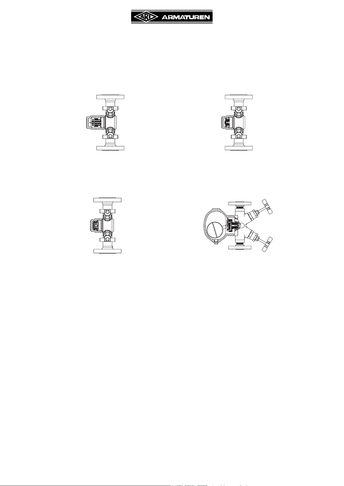
4.2 Operating principles
(refer to Fig. 1 - Fig. 2 page 6)
The product concept is based on a robust modular design with integrated shut-off valves
(ball / seat chamfer). This modular design can be used as the basis for steam traps with
several control systems.
- Bimetallic steam trap series 60A
- Thermostatic steam trap series 61A
- Thermodynamic stam traps series 64A
- Ball float steam traps series 63A
The valve is based on a hard-sealing (metal on metal) construction:
(refer to Fig. 7 page 10 - Fig. 8 page 11)
- body (pos. 1) / screw fitting (pos. 15)
- seat (pos. 3) / body (pos. 1)
- valve plug (pos. 4) / seat (pos. 3)
- safety back-sealing mechanism
Stop valve with gland packing: spindle (pos. 11) / screw fitting (pos. 15)
Stop valve with bellows seal: spindle (pos. 11) / spindle guide (pos. 16)
There are also graphite rings (pos. 5) which take over external sealing in the position
between “OPEN” or “SHUT”.
ATTENTION !
Do not use shut-off valves for OPEN-SHUT function to throttle volume flow.
Valve position:
OPEN - Safety back-sealing mechanism effective when valve fully open.
SHUT - Valve plug (pos. 4) / chamfer at seat (Pos 3) seal effective.
a) Bimetallic steam trap series 60A
(refer to Fig. 3 page 7)
(for particular description of the control system, refer to the Operating and installation
instruction of CONA B series 600
For regulation the steam trap uses both condensate temperature as well as available
upstream pressure and back pressure. As the temperature of the medium rises the
bimetallic plates arch, automatically reducing valve lift. An intermediately mounted
compression spring also influences valve lift in the lower pressure range, so that when
acting together with the bimetallic plates the controller always opens and closes a few
degrees below the upstream pressure boiling temperature. A pendulum-form support for
the valve spindle ensures consistent operation, irrespective of the position in which the
steam trap is mounted.
The steam trap vents air automatically during system start-up and operation.
The steam trap has a corrosion-resistant, water hammer-proof bimetallic controller, nonreturn protection, and a factory setting for average condensate sub-cooling of approx. 15K
(PN16-40).
The built-in controller is marked on the type plate as well as on the securing component.
Page 4 Rev. 0040808000 0808

Operating and installation instructions
®
CONA
b) Thermostatic steam trap series 61A
(refer to Fig. 4 page 7)
(for particular description of the control system, refer to the Operating and installation
instruction of CONA M series 610)
The steam trap uses the condensate temperature and available upstream pressure for
control. It vents automatically during system start-up and operation. It has a corrosionresistant, water hammer-proof diaphragm capsule which always discharges the
consistently supercooled condensate a few degrees below the upstream pressuredependent boiling temperature.
c) Thermodynamic stam traps series 64A
(refer to Fig. 4 page 7)
(for particular description of the control system, refer to the Operating and installation
instruction of CONA TD series 640)
For control the steam trap uses the condensate temperature as well as the available
upstream pressure and back pressure.
In the controller (pos. 24) the valve plate is enclosed by the cap and the seat. When the
boiling temperature of the medium is reached, a cushion of steam forms over the valve
plate and presses the valve plate onto the seal faces of the seat.
To a very great extent the external sealing cap (pos. 6) frees the steam trap (in PN40) from
environmental influences. The steam cushion collapses as a result of condensate formation
and the associated temperature drop.
All-in-one
The system pressure lifts the valve plate from the seat face. The steam trap opens and
removes condensate.
The steam trap vents air automatically during system start-up and operation, but with a time
lag. The steam trap acts as a non-return valve.
d) Ball float steam traps series 63A
(refer to Fig. 6 page 7 and Fig. 9 page 14)
(for particular description of the control system, refer to the Operating and installation
instruction of CONA SC series 634)
The steam trap is controlled by a swivel-mounted ball float (pos. 24.16).
If condensate is flowing towards the steam trap, the ball float (pos. 24.16) rises and opens
the discharge valve using the lever mechanism.
An intercoupled diaphragm capsule (pos. 24.17) ensures automatic start-up air venting
when cold.
If the amount of condensate decreases or if there is no condensate, the float ball
(pos. 24.16) falls and shuts the discharge valve.
The compact float ball (pos. 24.16) exerts level-dependent control on the valve ball
(pos. 24.4) by means of a lever mechanism. As the level of condensate rises, the valve ball
(pos. 24.4) is rolled off the valve bore by the lever mechanism, thus opening the valve. The
condensate can now drain away.
If the amount of inflowing condensate is less than the possible valve output or if there is no
condensate flow, the ball float (pos. 24.16) falls and the valve ball (pos. 24.4) rolls back
onto the valve bore. The valve is now closed.
Rev. 0040808000 0808 Page 5

4.3 Diagram
Operating and installation instructions
®
CONA
All-in-one
Fig. 1: Stop valve with gland packing
Fig. 2: Stop valve with bellows seal
Page 6 Rev. 0040808000 0808
 Loading...