


Operating and installation instructions
Butterfly valves
BR 012 - ZESA
®
BR 014 - ZIVA®-Z
Contents
1.0 General information on operating
instructions .....................................................2
2.0 Notes on possible dangers........................... 2
2.1 Significance of symbols ..........................................2
2.2 Explanatory notes on safety information .................2
3.0 Storage and transport .................................. 2
4.0 Description..................................................... 3
4.1 Scope of applications .............................................3
4.2 Operating principles ................................................3
4.3 Diagram - assembly ................................................4
4.4 Technical data - remarks.........................................6
4.5 Marking ...................................................................6
5.0 Installation...................................................... 7
5.1 General remarks on installation ..............................7
5.2 Installation of accessories .......................................7
5.3 Conversion from notch lever to lock lever ...............8
BR 013 - GESA
®
BR 015 - ZIVA®-G
5.4 Retrofitting the THErmo-Appliance
(ZESA THEA / GESA THEA) ................................. 9
5.5 Converting or retrofitting lever
(ZIVA-Z / ZIVA-G) ................................................. 10
6.0 Putting the valve into operation .................11
7.0 Care and maintenance.................................11
7.1 Changing seat and O-ring seal
(ZIVA-Z / ZIVA-G) ................................................. 12
8.0 Troubleshooting .......................................... 13
9.0 Troubleshooting table ................................ 13
10.0 Dismantling the valve or the top part ..... 14
11.0 Warranty / Guarantee ................................ 14
12.0 EC declaration of conformity................... 15
Rev. 0040201000 0511 englisch

Operating and installation instructions
®
ZESA
/ GESA® / ZIVA®-Z / ZIVA®-G
1.0 General information on operating instructions
These operating instructions provide information on mounting and maintaining the fittings.
Please contact the supplier or the manufacturer in case of problems which cannot be
solved by reference to the operating instructions.
They are binding on the transport, storage, installation, start-up, operation, maintenance
and repair.
The notes and warnings must be observed and adhered to.
- Handling and all work must be carried out by expert personnel or all activities must be
supervised and checked.
It is the owner’s responsibility to define areas of responsibility and competence and to
monitor the personnel.
- In addition, current regional safety requirements must be applied and observed when
taking the fittings out of service as well as when maintaining and repairing them.
The manufacturer reserves the right to introduce technical modifications at any time.
These Operating Instructions comply with the requirements of EU Directives.
2.0 Notes on possible dangers
2.1 Significance of symbols
ATTENTION !
. . .
Warning of general danger.
2.2 Explanatory notes on safety information
In these Operating and Installation Instructions dangers, risks and items of safety
information are highlighted to attract special attention.
Information marked with the above symbol and “ATTENTION!” describe practices, a failure
to comply with which can result in serious injury or danger of death for users or third parties
or in material damage to the system or the environment. It is vital to comply with these
practices and to monitor compliance.
All other information not specifically emphasised such as transport, installation, operating
and maintenance instructions as well as technical data (in the operating instructions,
product documentation and on the device itself) must also be complied with to the fullest
extent in order to avoid faults which in turn can cause serious injury to persons or damage
to property.
3.0 Storage and transport
ATTENTION !
- Protect against external force (like impact, vibration, etc.).
- Valve mountings such as actuators, handwheels, hoods must not be used to
take external forces, e.g. they are not designed for use as climbing aids, or as
connecting points for lifting gear.
- Suitable materials handling and lifting equipment should be used.
See catalog sheet for weights.
- At -20°C to +65°C.
- The paint is a base coat to protect against corrosion during transportation and storage. Do
not damage paint protection.
Page 2 Rev. 0040201000 0511
Operating and installation instructions
®
ZESA
/ GESA® / ZIVA®-Z / ZIVA®-G
4.0 Description
4.1 Scope of applications
Butterfly valves are used for “interruption or restriction of the flow of liquids and gases”.
ATTENTION !
- Refer to the data sheet for applications, limits on use and possibilities.
- Certain media require or preclude the use of special materials.
- The valves are designed for standard operating conditions. If conditions exceed
these requirements, e.g. aggressive or abrasive media, the operator should
state the higher requirements when ordering.
- Valves made from grey cast iron are not authorised for use in systems subject
to TRD 110.
The information complies to the Pressure Equipment Directive 97/23/EC.
It is the responsibility of the machine planner to ensure compliance.
The special markings on the valve must be taken into account.
Refer to the catalogue sheet to see which materials are used in standard versions.
Please contact the supplier or the manufacturer if you have any questions.
4.2 Operating principles
The valve is closed by turning the disc shaft clockwise.
The shaft moves through 90°.
Rev. 0040201000 0511 Page 3

4.3 Diagram - assembly
Operating and installation instructions
®
ZESA
rotated view
/ GESA® / ZIVA®-Z / ZIVA®-G
Material designation:
EP = EPDM or
NBR or
FPM
fig. 1: Butterfly valve ZESA® / GESA®
Material designation:
EP = EPDM or
NBR or
FPM
Bild 2: Butterfly valve ZIVA®-Z / ZIVA®-G
Refer to the data sheet for information about materials with designations and figure numbers.
Page 4 Rev. 0040201000 0511

Actuation arrangements
Operating and installation instructions
®
ZESA
/ GESA® / ZIVA®-Z / ZIVA®-G
fig. 3: Notch lever ZESA® / GESA
®
- The detent pin of the lower lever must be fully disengaged to move the lever.
fig. 4: Lock lever ZESA® / GESA
®
- The star knob screw must be slackened before and tightened again after moving the
lever.
fig. 5: Notch lever ZIVA®-Z / ZIVA®-G
- The detent pin of the lower lever must be fully disengaged to move the lever.
Rev. 0040201000 0511 Page 5

Operating and installation instructions
®
ZESA
/ GESA® / ZIVA®-Z / ZIVA®-G
Position indicator
Lock nut
fig. 6: Worm gear ZESA
- Gear type (actuation by hand wheel, clockwise for closing).
The CLOSE-position can be adjusted by ± 5° by a stop screw.
The stop screws are self-sealing and self-locking (refer to Fig. 7).
- Refer to separate operating and maintenance manual for drive (electric or pneumatic).
®
/GESA® and ZIVA®-Z/ ZIVA®-G
4.4 Technical data - remarks
for
- Principal dimensions
- Pressure-temperature-ratings, etc. refer to data sheet.
4.5 Marking
Details of the CE-marking on the valve:
CE-marking
0525 Notified body
Manufacturer
Typ Type
Address of manufacturer:
refer to item 11.0 Warranty / Guarantee
Bj. Year of manufacture
According to the Pressure Equipment Directive table 6, annex II, valves without safety
function are only allowed to bear the CE-marking DN32 onwards.
Page 6 Rev. 0040201000 0511

Operating and installation instructions
®
ZESA
/ GESA® / ZIVA®-Z / ZIVA®-G
5.0 Installation
5.1 General remarks on installation
The following points should be taken into account besides the general principles governing
installation work:
ATTENTION !
- Remove flange covers if present.
- The interior of valve and pipeline must be free from foreign particles.
- The direction of flow need not be taken into account.
- Steam line systems should be designed to prevent water accumulation.
- Lay pipelines so that damaging transverse, bending and torsional forces are
avoided.
- Protect valves from dirt during construction work.
- Connection flanges must mate exactly.
- Valve mountings such as actuators, handwheels, hoods must not be used to
take external forces, e.g. they are not designed for use as climbing aids, or as
connecting points for lifting gear.
- Flooding of the butterfly valve is not permissible.
- Suitable materials handling and lifting equipment should be used.
See data sheet for weights.
- The shaft can be in any position except for DN350 up to DN600 (horizontal
shaft preferably).
- No gaskets required between flanges, flexible gaskets are not allowed.
- The butterfly valve must be installed in open position if possible, but the disc
should not protrude beyond the housing.
- Large actuators with horizontal application must be supported.
- Avoid damage to the rubber sheathing during handling, storage and installation.
- Do not heat the valve (e.g. by welding, grinding, etc.) above its service
temperature (refer to data sheets).
- Protect actuators from excessive ambient temperatures
(refer to operating instructions for actuator).
- If the butterfly valve is in operation as a pipeend valve, regard DIN EN 294
point 5.
- Planners / construction companies or operators are responsible for positioning and
installing products.
- The valves are designed for application, not influenced from weather.
- For application outside or in adverse environments like corrosion-promoting conditions
(sea water, chemical vapours, etc.), special constructions or protective measures are
recommended.
- The valves are not permitted for subsurface installation.
5.2 Installation of accessories
Optional accessories (e.g. limit switches) supplies with valves must be fitted as required for
their functions as shown in the plants of the plant.
Rev. 0040201000 0511 Page 7

Operating and installation instructions
®
ZESA
/ GESA® / ZIVA®-Z / ZIVA®-G
5.3 Conversion from notch lever to lock lever
window
fig. 7
The notch lever cap (pos. 7) can be used for the conversion.
- Set notch lever (pos. 50) to notch position 4.
- Slacken socket screw (pos. 50.2 / SW 5 of 6 mm AF).
- Remove notch lever (pos. 50).
ATTENTION !
The position of the valve disc is not positively located!
- Dismantle notch lever cap (pos. 7) and use a screwdriver to break out the window.
- Put the cap, with the nut (pos. 19) in it, in place and tighten it.
- Set the lock lever (pos. 50.1) in position as shown in the diagram.
- Tighten the socket screw (pos. 50.2).
- Insert star knob screw (pos. 60) through the hole at the end of the lock lever (pos. 50.1)
and screw into the hex. nut (pos. 19).
If the lock lever must be on the same side as the original notch lever, the notch lever cap
must be turned through 180°.
For the angle limit stop, an additional nut can be placed in the cap for a locking screw.
Page 8 Rev. 0040201000 0511
Operating and installation instructions
®
ZESA
/ GESA® / ZIVA®-Z / ZIVA®-G
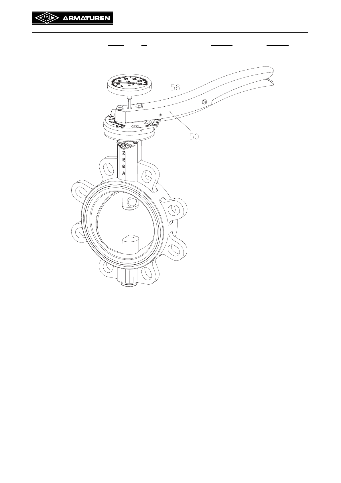
5.4 Retrofitting the THErmo-Appliance (ZESA®THEA / GESA®THEA)
fig. 8
- Remove sticker from the hole in the lever (pos. 50).
- Insert the THEA temperature indicator (pos. 58) into the hole down to the stop.
Rev. 0040201000 0511 Page 9

Operating and installation instructions
®
ZESA
/ GESA® / ZIVA®-Z / ZIVA®-G
5.5 Converting or retrofitting lever (ZIVA®-Z / ZIVA®-G)
Retrofit in butterfly valve with free shaft end:
fig. 9
ATTENTION !
- Do not remove shaft blowout protection (pos. 26) under pressure.
(see point 10.0 Dismantling the valve or the top part)
- The valve disc is not fixed in position without an actuating element!
- Slacken setscrew (pos. 50.1),
- Mount notch lever (pos. 50) on shaft end together with the notch disc (pos. 16)
(notch lever aligned with notch disc),
- Turn notch lever (pos. 50) until drillings in notch disc (pos. 16) and body are aligned,
- Assemble and tighten cheese-head screw (pos. 21) and nut (pos. 20),
- Tighten set screw (pos. 50.1).
Page 10 Rev. 0040201000 0511

Operating and installation instructions
ZESA
6.0 Putting the valve into operation
ATTENTION !
- Before putting the valve into operation, check material, pressure, temperature
and direction of flow.
- Regional safety instructions must be adhered to.
- Residues in piping and valves (dirt, weld beads, etc.) inevitably lead to leakage.
- Touching the valve when it is operating at high (> 50°C) or low (< 0°C) media
temperatures can cause injury.
Affix warning notice or protective insulation as appropriate!
Before putting a new plant into operation or restarting a plant after repairs or
modification, always make sure that:
- All works has been completed!
- The valve is in the correct position for its function.
- Safety devices have been attached.
®
/ GESA® / ZIVA®-Z / ZIVA®-G
7.0 Care and maintenance
Maintanance and maintenance-intervals have to be defined by the operator according to
the requirements.
ATTENTION !
- It is advisable to actuate the valve at least once a month.
- When used as an end-blockage, a safety precaution (e.g. plug-in disc, blind
flange etc.) is demanded by maintenance works.
Rev. 0040201000 0511 Page 11

7.1 Changing seat and O-ring seal
(ZIVA
®
-Z / ZIVA®-G)
Operating and installation instructions
®
ZESA
/ GESA® / ZIVA®-Z / ZIVA®-G
fig. 10
- Observe safety instructions
- Grease seat (pos. 2) when changing
Lubricant: e.g. Berusoft 30 valve grease
obtainable from: Carl Bechem GmbH, Weststrasse 120, D-58089 Hagen
or a lubricant suitable for this application.
ATTENTION!
- Always ensure that the lubricant is compatible with the medium.
- It is not safe to replace the O-ring seal (pos. 11) until the system has cooled
down and the plant is pressureless.
- For safety reasons we recommend that the O-ring seal (pos. 11) only be
changed when disassembled.
- Prior to disassembling the butterfly valve note points 10.0 and 11.0.
- When the butterfly valve is activated there is a crushing hazard between valve
disc and body.
- Maintenance work inside the pipeline (large nominal diameters) should only be
carried out when the butterfly valve is safely deactivated (disconnect actuator
from power supply).
Page 12 Rev. 0040201000 0511

Operating and installation instructions
®
ZESA
/ GESA® / ZIVA®-Z / ZIVA®-G
8.0 Troubleshooting
In the event of malfunction or faulty operating performance check that the installation and
adjustment work has been carried out and completed in accordance with these Operating
Instructions.
ATTENTION !
-
It is essential that the safety regulations are observed when identifying faults.
If malfunctions cannot be eliminate with the help of the following table
“9.0 troubleshooting table”, the supplier or manufacturer should be consulted.
9.0 Troubleshooting table
ATTENTION !
- read point 10.0 and 11.0 prior to dismantling and repair work!
- read point 6.0 before restarting the plant !
Fault Possible cause Corrective measures
No flow Valve closed. Open valve.
Little flow Valve not sufficiently open. Open valve.
Strainer sieve clogged. Clean / replace sieve.
Piping system clogged. Check piping system.
Valve is impossible or difficult to open or close
Service conditions (e.g. medium, temperature) outside permissible limits.
Replace valve. Consult supplier or
manufacturer.
Power failure. Check power supply.
Wrong direction of rotation. Turn in correct direction
(clockwise for opening).
Valve leaking Not properly closed. Close valve properly or readjust limit
switch/stop screw.
Pressure difference too high. Check plant.
Medium contaminated. Clean valve.
Install strainer sieve upstream of valve.
Valve with locking device
cannot be opened
Lining/collars (Fig. 1-2, item 2) or valve
disc (Fig. 1-2, item 3) damaged by foreign bodies or medium
Locking device tightened. Slacken locking device.
Replace valve. Consult supplier or
manufacturer.
Rev. 0040201000 0511 Page 13

Operating and installation instructions
®
ZESA
/ GESA® / ZIVA®-Z / ZIVA®-G
10.0 Dismantling the valve or the top part
ATTENTION !
The following points must be observed:
- Pressureless pipe system.
- Medium must be cool.
- Plant must be drained.
- Purge piping systems in case of caustic, inflammable, aggressive or toxic
media.
11.0 Warranty / Guarantee
The extent and period of warranty cover are specified in the "Standard Terms and
Conditions of Albert Richter GmbH & Co. KG“ valid at the time of delivery or, by way of
departure, in the contract of sale itself.
We guarantee freedom of faults in compliance with state-of-the-art technology and the
confirmed application.
No warranty claims can be made for any damage caused as the result of incorrect handling
or disregard of operating and installation instructions, datasheets and relavant regulations.
This warranty also does not cover any damage which occurs during operation under
conditions deviating from those laid down by specifications or other agreements.
Justified complaints will be eliminated by repair carried out by us or by a specialist
appointed by us.
No claims will be accepted beyond the scope of this warranty. The right to replacement
delivery is excluded.
The warranty shall not cover maintenance work, installation of external parts, design
modifications or natural wear.
Any damage incurred during transport should not be reported to us but rather to the
competent cargo-handling depot, the railway company or carrier company immediately or
else claims for replacements from these companies will be invalidated.
Technology for the Future.
GERMAN QUALITY VALVES
ARI-Armaturen Albert Richter GmbH & Co. KG, D-33756 Schloß Holte-Stukenbrock
Telephone (+49 5207) 994-0 Telefax (+49 5207) 994-158 or 159
Internet: http://www.ari-armaturen.com E-mail: info.vertrieb@ari-armaturen.com
Page 14 Rev. 0040201000 0511
Operating and installation instructions
®
ZESA
/ GESA® / ZIVA®-Z / ZIVA®-G
12.0 EC declaration of conformity
ARI-Armaturen Albert Richter GmbH & Co. KG,
Mergelheide 56-60, D-33756 Schloß Holte-Stukenbrock
EC declaration of conformity
as defined by
the Pressure Equipment Directive 97/23/EC
Herewith we declare,
that according to the above mentioned Pressure Equipment Directive (PED) the below
listed products comply and have been approved according to table 6, annex II, module H
through Lloyd´s Register Quality Assurance GmbH (BS-Nr. 0525), Am Sandtorkai 41,
D-20457 Hamburg.
Certificate-No: 50003/1
Butterfly valves ZESA® / GESA
Type 012, 013
®
Butterfly valves ZIVA
Applied standards:
Schloß Holte-Stukenbrock, 11.01.2010
®
-Z / ZIVA®-G
Type 014, 015
DIN 3840
...................................................
(Brechmann, Managing director)
Rev. 0040201000 0511 Page 15
 Loading...