

ARI Armaturen ARI-PREMIO User Manual
Operating and Installation Instructions
Thrust actuator ARI-PREMIO
Contents
1.0 General information on operating instructions...................................................................................... 3
2.0 Notes on possible dangers ...................................................................................................................... 3
2.1 Significance of symbols .................................................................................................................... 3
2.2 Explanatory notes on safety information............................................................................................ 4
3.0 Storage and transport............................................................................................................................... 4
4.0 Description ................................................................................................................................................ 5
4.1 Field of application ............................................................................................................................. 5
4.2 Method of functioning......................................................................................................................... 5
4.3 Diagram ............................................................................................................................................. 6
4.3.1 ARI-PREMIO 2,2 - 5 kN............................................................................................................ 6
4.3.2 ARI-PREMIO 12 - 15 kN........................................................................................................... 7
4.3.3 Parts list .................................................................................................................................... 8
4.4 Technical data .................................................................................................................................... 9
4.5 Dimensions ...................................................................................................................................... 12
5.0 Installation .............................................................................................................................................. 13
5.1 General installation data .................................................................................................................. 13
5.2 Manual operation ............................................................................................................................. 15
5.2.1 ARI-PREMIO 2.2 - 5 kN ......................................................................................................... 15
5.2.2 ARI-PREMIO 12 - 15 kN ........................................................................................................ 16
Rev. 0040501000 4511 englisch

5.3 Installation instructions for mounting to valves ................................................................................ 17
5.3.1 Mounting for valve-lift up to 30 mm (yoke version) ................................................................. 17
5.3.2 Mounting for valve lift over 30 mm to 80 mm (column version) .............................................. 19
5.4 Electrical connection........................................................................................................................ 21
5.4.1 Wiring diagram ARI-PREMIO 2.2 - 5 kN................................................................................. 21
5.4.2 Wiring diagram ARI-PREMIO 12 - 15 kN................................................................................ 22
5.4.2.1 ARI-PREMIO 12 - 15 kN 1 Ph~ / 3 Ph~ without reversing contactor ....................................... 22
5.4.2.2 ARI-PREMIO 12 - 15 kN 1 Ph~ / 3 Ph~ with reversing contactor ............................................23
5.4.3 Connection ............................................................................................................................. 24
5.5 Options and settings ....................................................................................................................... 25
5.5.1 Torque and travel switches ..................................................................................................... 25
5.5.2 Connection boards PA or NA (only 2.2 - 5 kN) ....................................................................... 25
5.5.3 Travel switch........................................................................................................................... 26
5.5.3.1 Installation of additional travel switches ...................................................................................27
5.5.3.2 Installation of trip slide and setting of the travel switch (S3) ....................................................29
5.5.3.3 Setting the additional travel switches (S4/S5 and S24/S25).................................................... 30
5.5.4 Potentiometers........................................................................................................................ 31
5.5.4.1 Installing the potentiometer ...................................................................................................... 31
5.5.4.2 Setting the potentiometer......................................................................................................... 33
5.5.5 Error-proof potentiometer for single-channel, error-proof position feedback ......................... 34
5.5.5.1 Setting the potentiometer on conductive plastic basis ............................................................. 34
5.5.6 Heating ................................................................................................................................... 36
5.5.6.1 Installation of heating ............................................................................................................... 36
5.5.7 Electronic position indicator RI21 ........................................................................................... 37
5.5.8 Electronic position controller ES11 ......................................................................................... 37
5.5.9 Electronic position indicator (RI21) and position controller (ES11) together in the actuator... 38
5.5.10 Integrated temperature controller dTRON 316 ..................................................................... 39
5.5.10.1 Installation of the dTRON 316................................................................................................39
5.5.11 Integrated reversing contactor .............................................................................................. 40
5.5.11.1 Installing the reversing contactor............................................................................................40
5.5.11.2 Electrical connection with ES11 or dTRON 316..................................................................... 40
5.5.12 Phase control relay ............................................................................................................... 41
5.5.12.1 Installing the phase control relay............................................................................................ 41
5.5.14 Electronic position indicator RI32 ......................................................................................... 46
5.5.14.1 Useful range of the linear motion potentiometer ...................................................................46
5.5.14.2 Installing the RI32 electronic position indicator in the PREMIO ............................................. 46
5.5.14.3 Electronic position indicator (RI32) and position controller (ES11)
together in the actuator ........................................................................................................................ 47
5.5.14.4 Technical data - Position indicator RI32 ................................................................................. 48
5.5.14.5 Potentiometer installation ......................................................................................................48
5.5.14.6 Wiring diagram ......................................................................................................................49
5.5.14.7 Connection conditions ............................................................................................................ 49
5.5.14.8 Setting zero point and slope span.......................................................................................... 50
6.0 Putting the actuator into operation ...................................................................................................... 51
7.0 Care and maintenance............................................................................................................................ 51
8.0 Troubleshooting...................................................................................................................................... 51
9.0 Troubleshooting table ............................................................................................................................ 52
10.0 Dismantlement of thrust actuator ....................................................................................................... 53
11.0 Warranty / Guarantee ............................................................................................................................ 53
12.0 EC declaration of conformity ............................................................................................................... 54
Operating and installation instructions
Thrust actuator ARI-PREMIO
1.0 General information on operating instructions
These operating instructions provide information on mounting and maintaining the fittings.
Please contact the supplier or the manufacturer in case of problems which cannot be
solved by reference to the operating instructions.
They are binding on the transport, storage, installation, start-up, operation, maintenance
and repair.
The notes and warnings must be observed and adhered to.
- Handling and all work must be carried out by expert personnel or all activities must be
supervised and checked.
It is the owner’s responsibility to define areas of responsibility and competence and to
monitor the personnel.
- In addition, current regional safety requirements must be applied and observed when
taking the fittings out of service as well as when maintaining and repairing them.
The manufacturer reserves the right to introduce technical modifications at any time.
These Operating Instructions comply with the requirements of EU Directives.
2.0 Notes on possible dangers
2.1 Significance of symbols
ATTENTION !
. . .
ATTENTION !
. . .
Warning of general danger.
Warning of dangerous voltage.
Exposed to injury!
Don’t touch the turning handwheel when the motor is running.
Exposed to injury!
Don’t put your hand into the up or downwards moving
appliance.
Danger when not observing the operating and installation
instructions!
Before installing, operating, maintenance or dismantling read
and observe the instructions.
Danger though voltage!
Before dismantling the hood, switch of the electrical source
and secure against turning on again.
0040501000 4511 Page 3

Operating and installation instructions
Thrust actuator ARI-PREMIO
2.2 Explanatory notes on safety information
In these Operating and Installation Instructions dangers, risks and items of safety
information are highlighted to attract special attention.
Information marked with the above symbol and “ATTENTION ! ” describe practices, a
failure to comply with which can result in serious injury or danger of death for users or third
parties or in material damage to the system or the environment. It is vital to comply with
these practices and to monitor compliance.
All other information not specifically emphasised such as transport, installation, operating
and maintenance instructions as well as technical data (in the operating instructions,
product documentation and on the device itself) must also be complied with to the fullest
extent in order to avoid faults which in turn can cause serious injury to persons or damage
to property.
3.0 Storage and transport
ATTENTION !
- Valve mountings such as drives, handwheels, hoods must not be used to take
external forces, e.g. they are not designed for use as climbing aids, or as
connecting points for lifting gear.
Non-compliance may lead to death, injury or damage to property due to
persons falling or parts being dropped.
- Suitable materials handling and lifting equipment should be used.
See “4.4 Technical data” for weights.
- At -20° to +70°C dry, free from dirt.
- Do not unpack thrust drive or setting equipment assembly prior to installation.
- Protect against external force (impact, vibration etc.).
- Do not soil or damage type identification plate and wiring diagram on the controller.
Page 4 0040501000 4511

Operating and installation instructions
Thrust actuator ARI-PREMIO
4.0 Description
4.1 Field of application
ARI-PREMIO linear thrust actuators are employed to actuate control or shut-off valves
requiring a nominal linear stroke distance of up to 80 mm and thrust from 2.2 kN to 15 kN.
The thrust actuators are set to the thrust forces specified in the technical data. If supplied
with the valve, the lift of the thrust actuator will be set to the stroke distance of the valve.
Selection of the proper actuator version in alignment with the corresponding fitting as well
as use of the thrust actuator in accordance with the specified technical data is the
responsibility of the systems engineer.
See data sheet for areas of application, application limits and potential.
Any use of the thrust actuator beyond the specified technical data or improper use of the
actuator is deemed to be not for the intended purpose.
The ambient conditions have to be conform to the actual electromagnetic compatibility
directives. Additional the compatibility to this directives has to be maintained in case of
expansion or other changing of the ambient conditions.
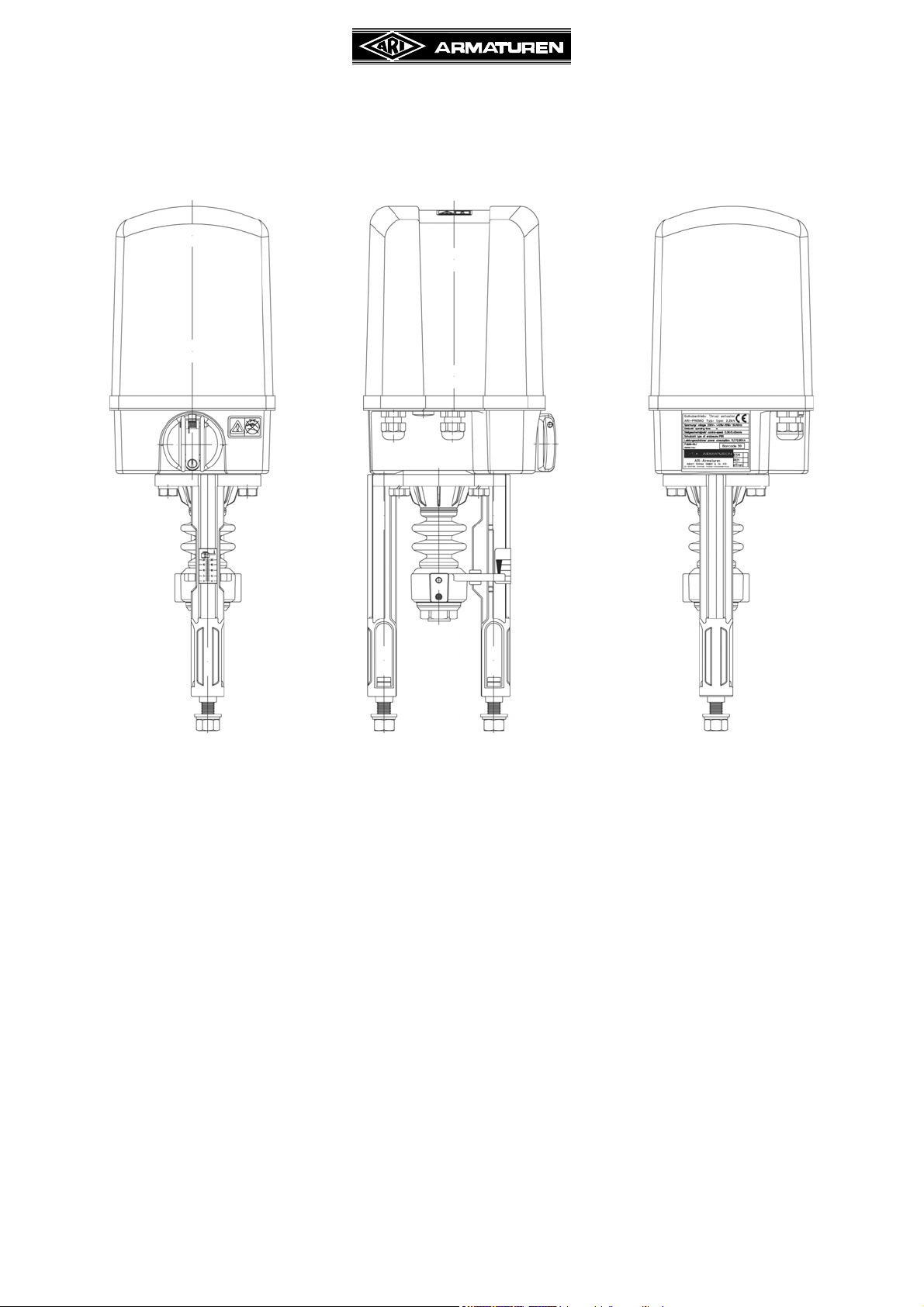
4.2 Method of functioning
The thrust actuator, fitted with a yoke or columns, is mounted to the valve.
Transfer of force is effected via a coupling safeguarded against torsion.
The torsion safeguarding feature also serves as a lift indicator.
The lift settings can be read off on a lift dial attached to the yoke or between the 2-ear
clamps mounted to the column.
The electrical components are accommodated separately from the gearbox underneath a
sealed hood, thus being protected against operating and environmental effects.
Following removal of the hood, easy access is provided to the switchgear and indicating
feature.
The rotary motion of the motor is transmitted to the spindle nut by means of spur gear.
The drive spindle, which is safeguarded against torsion, screws its way into the spindle nut
and thus performs a pull or push motion depending on the sense of rotation.
In the final positions of the valve, the spindle nut is pressed against a set of springs so as to
produce closing force.
The motor is switched-off by means of two load-dependent switches and one strokedependent switch. For the function of the stroke-dependent travel switch (S3), an optionally
available trip slide is necessary. The load-dependent switches will also switch-off the motor
if foreign bodies have lodged themselves between the valve seat and cone.
The load-dependent switches serve to protect the valve and thrust actuator against
damage.
0040501000 4511 Page 5
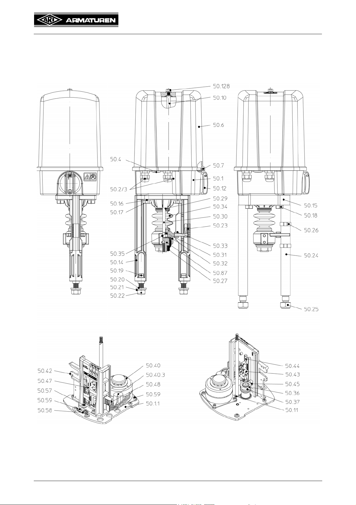
4.3 Diagram
4.3.1 ARI-PREMIO 2,2 - 5 kN
Yoke Version Column Version
Operating and installation instructions
Thrust actuator ARI-PREMIO
Fig. 1
Page 6 0040501000 4511
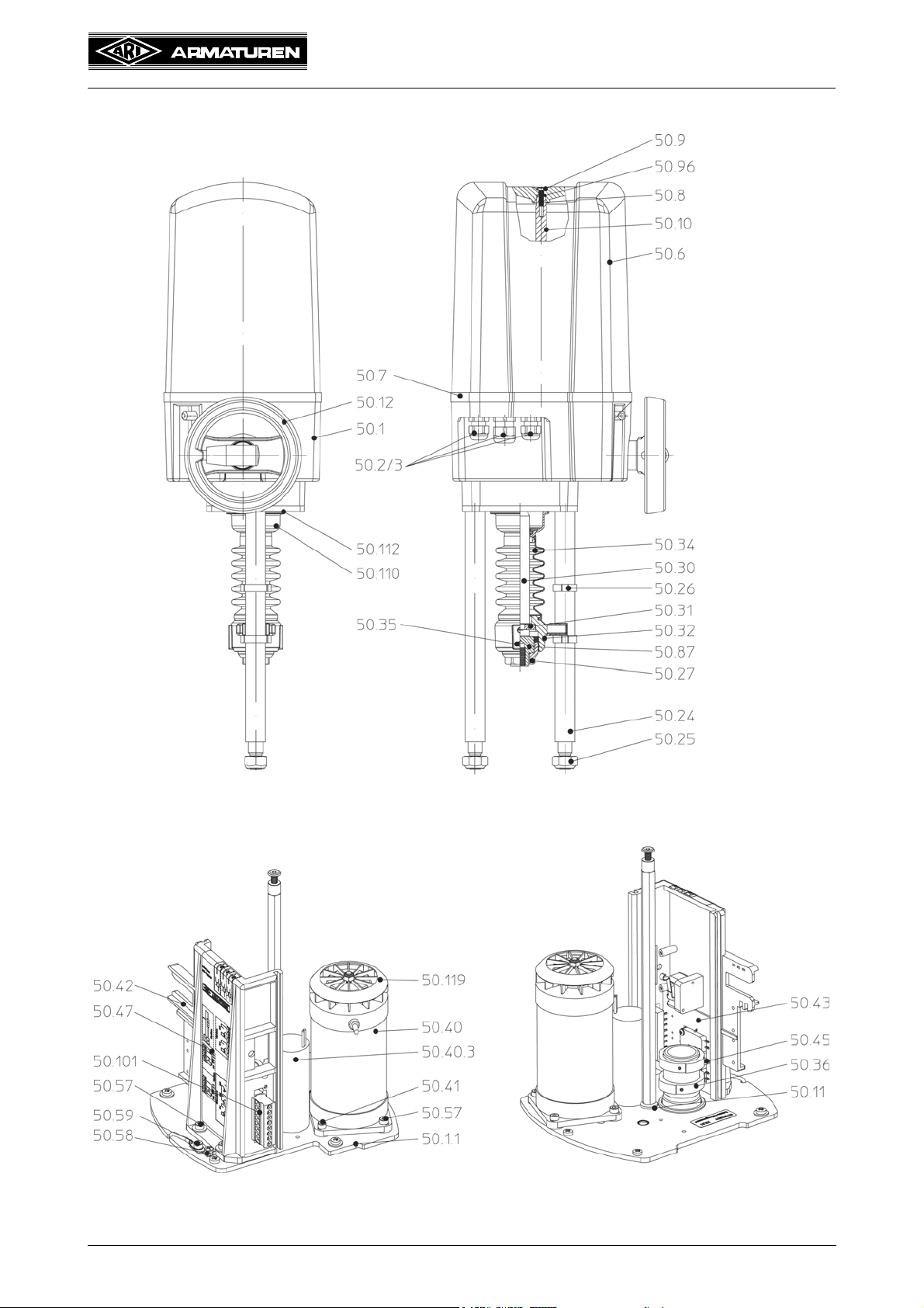
4.3.2 ARI-PREMIO 12 - 15 kN
Operating and installation instructions
Thrust actuator ARI-PREMIO
Fig. 2
0040501000 4511 Page 7

Operating and installation instructions
Thrust actuator ARI-PREMIO
4.3.3 Parts list
Pos. Designation Pos. Designation
50.1 Gearbox 50.30 Driving spindle
50.1.1 Gearbox cover plate 50.31 Spindle safety feature
Cable gland
50.2
50.4 Sealing plug 1 x M16x1,5 50.36 Set collar
50.6 Hood 50.37 Grub screw DIN 913-M3x5
50.7 Hood seal 50.40 Synchronous motor, complete
50.8 Counter-sunk screw DIN EN ISO
50.9 Sealing washer DIN EN ISO 7089 50.41 Head cap screw
50.10 Column 50.42 Board support
50.11 Conical spring washer 50.43 Standard board
50.12 Handwheel 50.43.1 Directional switch (valve – up) S3
50.12.1 Turning handle of handwheel 50.43.2 Torque switch
50.14 Yoke 50.45 Shift lever
50.15 Flange 50.46 Washer
50.16 Spring washer DIN 128-A10 50.47 Wiring diagram sticker, standard
2.2 - 5kN: 2 x M16x1,5
12 - 15kN: 2 x M16x1,5 /
1 x M20x1,5
10642 - M5x20
50.32 Torsion safety feature
50.34 Bellow
50.35 Grub screw DIN ISO 4766 - M6
50.40.3 Motor capacitor
DIN EN ISO 4762-M4 - 18
50.17 Hexagon head screw
DIN EN ISO 4017 - M10x40
50.18 Hexagon head screw
DIN EN 24017-M10x55
50.19 T-head bolt DIN 261-M12x40 50.58 Protective conductor terminal
50.20 Washer DIN EN ISO 7089 50.59 Head cap screw
50.21 Spring washer DIN 128-A12 50.87 Threaded bush
50.22 Hexagon nut DIN EN ISO 4032 - M12 50.96 O-ring DIN 3771 – 4 x 1.8
50.23 Lift dial 50.101 Connector, 8-pole
50.24 Distance column 50.110 Gear cap
50.25 Hexagon nut DIN 980-V-M16 50.115 O-ring DIN 3771 - 52x2.5
50.26 2-ear clamp (stroke indicator) 50.119 Fan wheel
50.27 Coupling 50.128 Collar nut Seal lock M6
50.48 Connector, 3-pole (standard)
50.57 Head cap screw
DIN EN ISO 4762 - M4x10
DIN EN ISO 4762 - M4x6
Page 8 0040501000 4511

Operating and installation instructions
Thrust actuator ARI-PREMIO
4.4 Technical data
Typ e ARI-PREMIO
Thrust force kN 2,2 5,0 12,0 15,0
Stroke distance max. mm 50 80
Duty classification acc. to EN 60034-1 S3 80% DC / max.1200 c/h S3 50% DC / max. 1200 c/h
Control speed mm/sec. 0,38 0,38 1,0 0,38 0,79 0,38
Motor voltage 230V - 50Hz / 60Hz
Power consumption W 21 33 75 69 85 69
For power consumption of other voltages and frequencies refer to type plate or on
1)
230V - 50Hz
request.
Torque switch 2 pcs., permanently wired,
switching capacity 10A, 250V~
Travel switch
2)
1 pcs., permanently wired,
switching capacity 10A, 250V~
2 pcs., permanently wired
switching capacity 16A, 250V~
1 pcs.,
permanently wired
switching capacity 16A, 250V~
Enclosure IEC 60529 IP 65
Max. storage temperature -40 °C ... +85 °C
Max. permissible ambient temperature -20 °C ... +70 °C
For operation outside or at freezing temperature a heating is recommended.
Handwheel Yes (rotating during operation) Yes (engageable)
Mounting position Any. Exception: motor must not be suspended downwards
Gear lubricant
Klüber Isoflex Topas NB152
Molyduval
Valenzia H2
Weight kg 5.4 6 6.5 10.5
1)
Control speed and power consumption are 20% higher at frequency of 60 Hz
2)
Option trip slide necessary
Additional voltages / frequencies
Typ e ARI-PREMIO
Thrust force kN 2,2 5,0 12,0 15,0
Control speed mm/sec. 0,38 0,38 1,0 0,38 0,79 0,38
Voltages
24V - 50/60Hz
24V - DC
115V - 50/60Hz
3~400V - 50/60Hz
1)
Control speed and power consumption are 20% higher at frequency of 60 Hz
2)
further information / technical data for DC-version refer to item 5.5.14 Electronic position indicator RI32
3)
S3 50%ED / max 1200 c/h
1)
2)
1)
1)3)
24V - 50Hz
24V - 60Hz
24V - DC
2)
115V - 50/60Hz
1)
0040501000 4511 Page 9
24V - 50Hz / 24V - 60Hz
24V - DC
2)
115V - 50Hz / 115V - 60Hz
230V - 60Hz
1)
3~400V - 50Hz / 3~400V - 60Hz
1)
1)
1)

Accessories
Trip slide Necessary for operation:
- for actuating travel switch S3 / retracting spindle
(the travel switch S3 exists already in the standard version of the actuator)
- for potentiometer
- for additional position switches S4 / S5
Operating and installation instructions
Thrust actuator ARI-PREMIO
Additional intermediate
position switches
4)5)
S4, S5
Potentiometer
4)
Electronic
position controller
4)
(for controlling actuator with
analogue control signal)
Type Standard - 2 pcs., zero potential, switching capacity 10A, 250V~
Type Low-voltage
Conductive plastic
(max. 2 pcs.)
- 2 pcs., zero potential, with gold contacts,
switching capacity max. 0,1A, 4-30V
- 500, 1000, 2000, 5000 ohm; 1 W
Wire (max. 2 pcs.) - 100, 200 ohm; 1 W
Contactless (max. 1 pc.)
- Only in conjunction with RI22
- Feedback signal corresponds to RI22
- TÜV-approved conductive plastic potentiometer, suitable as a
position feedback sensor for control devices in electronic systems
TÐúV-approved
potentiometer
(max. 2 pcs.)
used to regulate and monitor fuel, air and exhaust gas streams in
combustion plants
- 5000 ohm
- Or optionally: 100, 200, 500, 1000 ohm; 1.5 W
- Not suitable for retrofitting!
- Control signals 0(2)...10V or 0(4)...20mA; electrical isolation
Type ES11
between mains voltage and control signal
- Incl. potentiometer
(note the maximum number of potentiometers)
Type PREMIO-Plus
(see separate data sheet /
operating instructions)
- Control signals: 3-step, 0-10V or 4-20mA
- Automatic initialisation
- Optional position feedback
- Electrical isolation between mains voltage and control signal
RI22
Electronic
position indicator
4)
(for position feedback with
analogue control signal)
RI32
Heating Heating resistor
Typ e
Standard PA
Connection board
4)
Type Low-voltage NA
- Analogue output for position feedback 0(4)...20mA, optional
switching to 0(2)-10V, output can be inverted; electrical isolation
between mains voltage and position feedback signal
- Optional display for indicating position feedback signal in mA or V
- Incl. potentiometer
(note the maximum number of potentiometers)
- Analogue output for position feedback
2...10V; 4...20 mA
- Compact design; 2 or 4-wire circuit
- Power supply: 24V AC/DC
- Incl. potentiometer
(note the maximum number of potentiometers)
- (With automatic switching circuit)
230V AC, 115V AC, 24V AC, 15W
- Zero potential, switching capacity 10A, 250V~
- (Also possible with standard version for operation at 12/15kN)
- Zero potential, with gold contacts,
max. switching capacity 0.1A, 4-30V
Page 10 0040501000 4511

Process controller
Typ e
Process controller
dTRON 316
Operating and installation instructions
Thrust actuator ARI-PREMIO
- Built into actuator
- 3-state stepper controller with 2 solid state relay outputs for direct
control of PREMIO actuators with a 3-step signal
- Compatible with resistance thermometers and thermocouples
(provided by customer), or standardized active current or voltage
signals,
- Preconfigured for temperature control:
Control range: -200°C to +850°C (resistance thermometer)
- Not compatible for use with the ES11!
Integrated
400V 3~ Acessories
4)
Option trip slide necessary
5)
Gold contacts should be used for low switching capacities and aggressive atmosphere
reversing contactor
Phase control relay -Only in addition with integrated reversing contactor!
-Only 1 electronic module possible!
0040501000 4511 Page 11
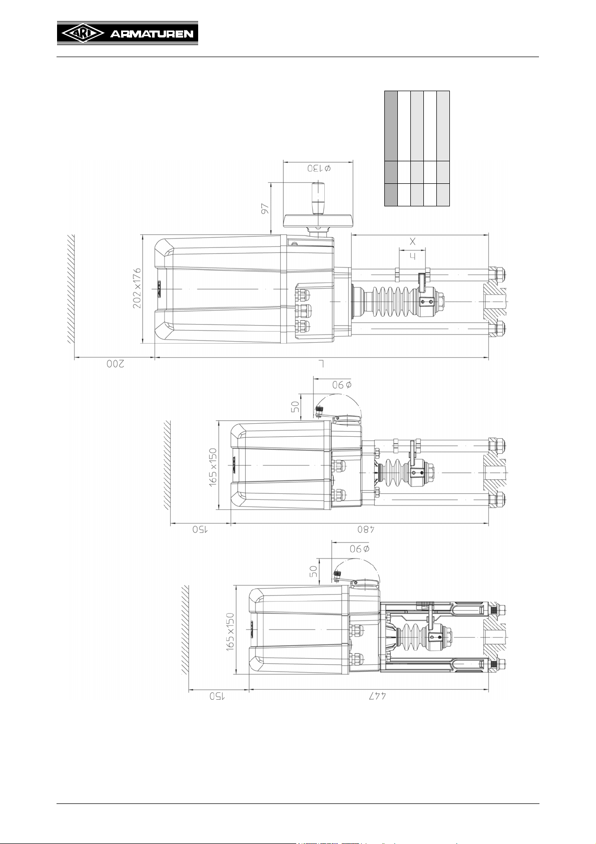
4.5 Dimensions
Operating and installation instructions
Thrust actuator ARI-PREMIO
X L h
256 622 max. 50 mm
271 637 max. 65 mm
286 652 max. 80 mm
236 602 max. 30 mm
removal of hood
Clearance required for
removal of hood
Clearance required for
ARI-PREMIO 12 - 15 kN
Nominal stroke max. 80 mm
ARI-PREMIO 2,2 - 5 kN
Nominal stroke > 30 mm - 50 mm
removal of hood
Clearance required for
Fig. 3
Page 12 0040501000 4511
ARI-PREMIO 2,2 - 5 kN
Nominal stroke max. 30 mm

Operating and installation instructions
Thrust actuator ARI-PREMIO
5.0 Installation
ATTENTION !
- Work on electrical systems or equipment must only be carried out by qualified
electricians or by trained individuals under the guidance and supervision of a
qualified electrician in compliance with regional electrical safety requirements
and regulations.
- Valve mountings such as drives, handwheels, hoods must not be used to take
external forces, e.g. they are not designed for use as climbing aids, or as
connecting points for lifting gear.
Non-compliance may lead to death, injury or damage to property due to
persons falling or parts being dropped.
- Actuator components which rotate or move during operation are coloured red.
Crushing and injury hazard!
5.1 General installation data
- In addition to general installation guidelines, the following points are required to be
observed:
- Planners / construction firms and operators are responsible for positioning and installing
the products.
ATTENTION !
- A voltage is induced in the thrust actuator motor. This induction voltage may be
higher than the operating voltage.
- For this reason relays and electronic load relays for thrust actuator control
require a protective circuit. The contacts of unprotected relays may stick after a
while.
- This may result in reversed directions of rotation or defective switch-off
Recommended safety circuit for relays and electronic load relays:
Connect a varistor or RC module parallel to each relay point.
Varistor S10K385 to S10K460
RC module 100 Ohm / 100nF
Where relay points and electronic load relays are particularly sensitive a coil should be
connected in series additionally to each relay point.
Recommended coil:
Toroidal coil 2mH / 2A
- Contactors of 16A and upwards do not need a safety circuit.
- Check thrust actuator for damage prior to fitting.
Damaged parts must be replaced by original spares.
- Existing operating instructions for valve.
- Complete valve with crossarm.
- Valve cone approximately in mid lift position - on no account supported inside a seat!
- Electrical installation in accordance with current regional regulations.
- Conductor cross-section selected to correspond to the given drive power and existing line
length.
0040501000 4511 Page 13
Operating and installation instructions
Thrust actuator ARI-PREMIO
- Mains fuse rating max. 6A.
- Circuit breakers in the plant to cut off the mains supply to the actuator.
- Conformity of technical data on thrust actuator with field conditions.
- Mains voltage in accordance with data specified on rating plate of thrust actuator.
- Thrust actuator complete with yoke or distance columns and coupling parts intended for
mounting to the corresponding valve.
- Ease of access to installation site.
- Adequate clearance space above the thrust actuator for removing the hood
(refer to point 4.5 Dimensions).
- Install where there is protection against high-energy heat radiation.
- The ambient temperature must be between -20°C and +70°C.
If installed outdoors, the thrust actuator must be provided with an additional cover to protect
against
- rain,
- direct insulation,
- dust.
In case of widely fluctuating ambient temperatures, high atmospheric humidity and
temperatures below the freezing point, your are recommended to install a heating resistor
to minimise condensation buildup in the actuator.
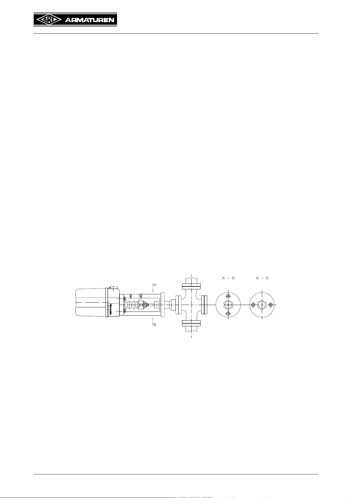
- Thrust actuator mountable in any position except in downward suspended position.
If installed with a horizontal connecting rod, the thrust actuator must be mounted so both
yoke legs or columns are on top of one another in the vertical plane (see Fig. 4 ).
Fig. 4
Page 14 0040501000 4511
Correct Incorrect

Operating and installation instructions
Thrust actuator ARI-PREMIO
5.2 Manual operation
5.2.1 ARI-PREMIO 2.2 - 5 kN
ATTENTION !
- The handwheel always rotates during motor-driven operation (running
indicator). Never activate manual operation while the motor is running.
Injury hazard!
- In the manual operating mode pay careful attention in the final positions that the
handwheel is only turned to the point where the torque switch trips (audible
click) as otherwise damage will be caused to the thrust actuator! Since the
handwheel always follows during motor-driven operation (running indication),
never operate by hand while the motor is running - potential injury hazards!
With the motor in the stationary state, the thrust actuator can be run in the retracted and
extended state with the handwheel firmly meshed with the gear.
Proceed as follows:
- Swing out lever (pos. 50.12.1) from handwheel (pos. 50.12).
- Turning in clockwise direction --> extending spindle.
- Turning in counter-clockwise direction --> retracting spindle.
retracting spindle
Fig. 5
extending spindle
0040501000 4511 Page 15
Operating and installation instructions
Thrust actuator ARI-PREMIO
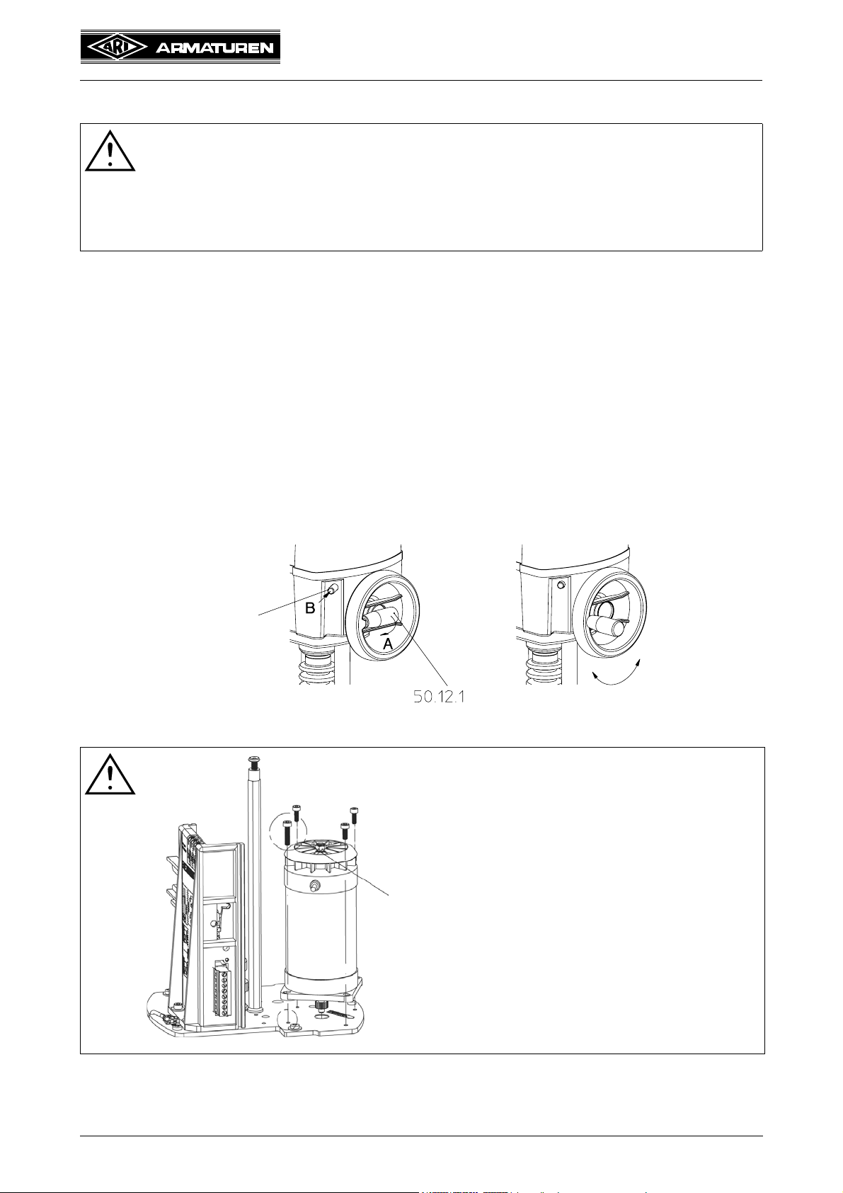
5.2.2 ARI-PREMIO 12 - 15 kN
ATTENTION !
- Do not attempt to engage manual operation until the motor has stopped.
Switching over while the motor is running may damage the thrust actuator.
- In the manual operating mode pay careful attention in the final positions that the
handwheel is only turned to the point where the torque switch trips (audible
click) as otherwise damage will be caused to the thrust actuator!
With the motor in the stationary state, the thrust actuator can be run in the retracted and
extended state with the engageable handwheel.
Proceed as follows:
- Fold the turning handle out of the handwheel (A)
- Turn the handwheel slightly and push in the engaging button for manual mode (B)
--> the button engages
- Turning in clockwise direction --> extending spindle
- Turning in counter-clockwise direction --> retracting spindle
The motor is no longer in mesh when the handwheel is engaged. The handwheel is
automatically disengaged when the motor starts and the motor is once more in mesh.
Engaging button
for manual mode
extending
retracting
Fig. 6
ATTENTION !
When changing the motor, it’s necessary to
observe for a correct function of the manual
operating device, that the head-cap screw
M4x18 is screwed in the right place.
Page 16 0040501000 4511
Operating and installation instructions
Thrust actuator ARI-PREMIO
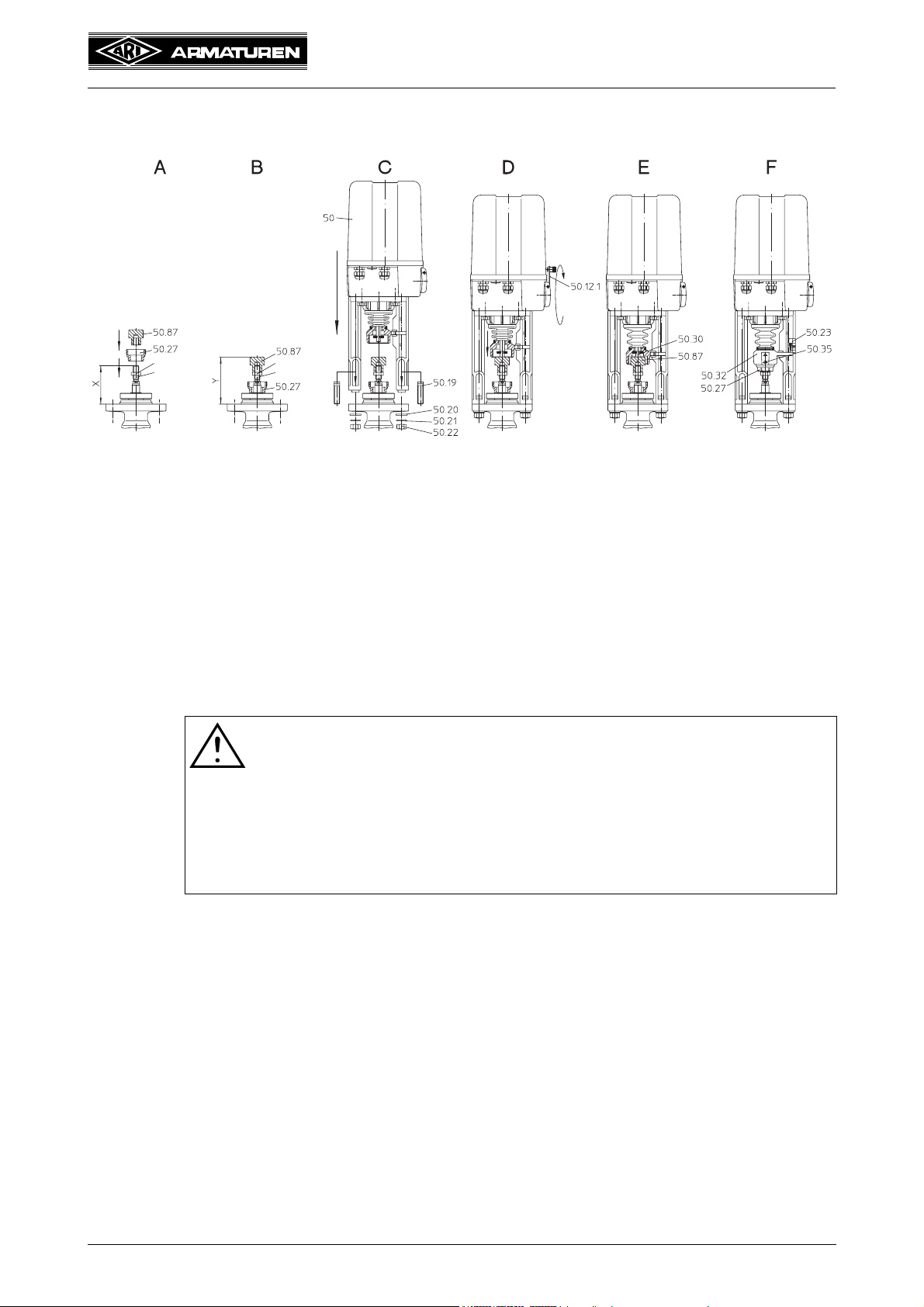
5.3 Installation instructions for mounting to valves
5.3.1 Mounting for valve-lift up to 30 mm (yoke version)
turn
Hexagon nut
Valve spindle
Hexagon nut
Valve s pind le
Fig. 7
To mount the thrust actuator to a valve having a nominal lift of up to 30mm, proceed
as follows:
- Screw coupling (pos. 50.27) out of torsion safety feature (pos. 50.32) of thrust
actuator (not illustrated).
- Position valve cone approximately in mid lift position.
Fig. A: - Turn flat hexagon nut if not present on valve spindle.
Fig. A-B: - Slip coupling (pos. 50.27) over valve spindle.
- Screw threaded bush (pos. 50.87) matching the valve onto the valve spindle in
accordance with setting dimension (Y) and lock with hexagon nut.
ATTEN TION !
Setting dimension (Y) and fitting-projection (X) are measured with
inserted valve spindle. This means for
- 2-way valves at closed valve,
- 3-way valves with mixing plug at closed way B,
- 3-way valves with diverting plug at closed way A
After measuring put the valve plug back in the mid lift position!
- Setting dimension (Y) for fitting-projection (X) 60 and 83mm = 102mm.
Fig. C: - Place thrust actuator (pos. 50) on valve.
- Mount thrust actuator (pos. 50) on fitting with two T-head bolts (pos. 50.19), two
washers (pos. 50.20), two spring washers (pos. 50.21), two hexagon nuts
(pos. 50.22).
Fig. D/E: - Swing out handwheel lever (pos. 50.12.1) and use it to move out the thrust
actuator until the driving spindle (pos. 50.30) comes to rest on the threaded
bush (pos. 50.87).
0040501000 4511 Page 17
 Loading...