

ARI Armaturen ARI-PACO 0, 85kN User Manual
Operating and installation instructions
Electric thrust actuator
ARI-PACO 0,85kN
Contents
1.0 General information on operating instructions................................................................................................ 3
2.0 Notes on possible dangers ................................................................................................................................ 3
2.1 Significance of symbols .................................................................................................................................... 3
2.2 Explanatory notes on safety information ........................................................................................................... 4
3.0 Storage and transport......................................................................................................................................... 4
4.0 Description .......................................................................................................................................................... 5
4.1 Field of application ............................................................................................................................................ 5
4.2 Method of functioning........................................................................................................................................ 5
4.3 Diagram............................................................................................................................................................. 6
4.3.1 ARI-PACO 0,85 kN ......................................................................................................................................... 6
4.3.1.1 Parts ...........................................................................................................................................................................6
4.4 Technical data - Remarks.................................................................................................................................. 7
4.5 Dimensions ....................................................................................................................................................... 8
5.0 Installation .......................................................................................................................................................... 9
5.1 General installation data ................................................................................................................................... 9
5.2 Manual operation ............................................................................................................................................ 10
5.2.1 ARI-PACO 0,85 kN ....................................................................................................................................... 10
5.3 Assembly instructions to the mounting on valves ............................................................................................11
5.3.1 Mounting of valve ARI-PACO 0,85 kN ..........................................................................................................11
Rev. 0040506000 1811 englisch

5.4 Electrical connection ....................................................................................................................................... 12
5.4.1 Wiring diagram ARI-PACO 0,85 D................................................................................................................ 12
5.4.2 Wiring diagram ARI-PACO 0,85 Y................................................................................................................ 12
5.4.3 Connection ARI-PACO ................................................................................................................................. 13
5.4.3.1 ARI-PACO 0,85 D......................................................................................................................................................13
5.4.3.2 ARI-PACO 0,85 Y ......................................................................................................................................................14
5.5 Settings .......................................................................................................................................................... 14
5.5.1 Torque switch off........................................................................................................................................... 15
5.5.2 Additional switching module in the ARI-PACO 0,85 D.................................................................................. 15
5.5.2.1 Insertion of the switching module in the ARI-PACO 0,85 D ......................................................................................16
5.5.2.2 Connection and adjustment of the switching module in the ARI-PACO 0,85 D .......................................................17
5.5.3 Relay card ARI-PACO 0,85 Y....................................................................................................................... 18
5.5.3.1 Insertion of the relay card in the ARI-PACO 0,85 Y .................................................................................................18
5.5.3.2 Connection and adjustment of the relay card in the ARI-PACO 0,85 Y....................................................................19
5.5.4 Potentiometer in the ARI-PACO 0,85 .......................................................................................................... 20
5.5.4.1 Mounting of the potentiometer in the ARI-PACO 0,85...............................................................................................20
6.0 Putting the actuator into operation ................................................................................................................. 21
6.1 Putting the actuator into operation ARI-PACO 0,85 D ................................................................................... 21
6.1.1 Overload recognition ARI-PACO 0,85 D....................................................................................................... 21
6.2 Putting the actuator into operation ARI-PACO 0,85 Y .................................................................................... 22
6.2.1 Automatic initialization, ARI-PACO 0,85 Y.................................................................................................... 23
6.2.2 Functions table for LED display in the ARI-PACO 0,85 Y ............................................................................ 24
6.2.3 Frost protection function, ARI-PACO 0,85 Y ................................................................................................ 24
6.2.4 Valve blocking protection, ARI-PACO 0,85 Y ............................................................................................... 25
6.2.5 Adaptation of the valve functions, ARI-PACO 0,85 Y ................................................................................... 26
6.2.6 Automatic Malfunction message, ARI-PACO 0,85 Y .................................................................................... 27
6.2.7 Overload recognition, ARI-PACO 0,85 Y...................................................................................................... 28
6.2.8 Zero-Crossing, ARI-PACO 0,85 Y ................................................................................................................ 28
7.0 Care and maintenance...................................................................................................................................... 28
8.0 Troubleshooting................................................................................................................................................ 28
9.0 Troubleshooting table ...................................................................................................................................... 29
10.0 Dismantlement of thrust actuator ................................................................................................................. 30
11.0 Warranty / Guarantee ...................................................................................................................................... 31
12.0 EC declaration of conformity ......................................................................................................................... 32

Operating and installation instructions
Electric thrust actuator ARI-PACO 0,85 kN
1.0 General information on operating instructions
These operating instructions provide information on mounting and maintaining the fittings.
Please contact the supplier or the manufacturer in case of problems which cannot be
solved by reference to the operating instructions.
They are binding on the transport, storage, installation, start-up, operation, maintenance
and repair.
The notes and warnings must be observed and adhered to.
- Handling and all work must be carried out by expert personnel or all activities must be
supervised and checked.
It is the owner’s responsibility to define areas of responsibility and competence and to
monitor the personnel.
- In addition, current regional safety requirements must be applied and observed when
taking the fittings out of service as well as when maintaining and repairing them.
The manufacturer reserves the right to introduce technical modifications at any time.
These Operating Instructions comply with the requirements of EU Directives.
2.0 Notes on possible dangers
2.1 Significance of symbols
ATTENTION !
. . .
ATTENTION !
. . .
Warning of general danger.
Warning of dangerous voltage.
Exposed to injury!
Don’t touch the turning handwheel when the motor is running.
Exposed to injury!
Don’t put your hand into the up or downwards moving
appliance.
Danger when not observing the operating and installation
instructions!
Before installing, operating, maintenance or dismantling read
and observe the instructions.
Danger though voltage!
Before dismantling the hood, switch of the electrical source
and secure against turning on again.
0040506000 1811 Page 3

Operating and installation instructions
Electric thrust actuator ARI-PACO 0,85 kN
2.2 Explanatory notes on safety information
In these Operating and Installation Instructions dangers, risks and items of safety
information are highlighted to attract special attention.
Information marked with the above symbol and “ATTENTION ! ” describe practices, a
failure to comply with which can result in serious injury or danger of death for users or third
parties or in material damage to the system or the environment. It is vital to comply with
these practices and to monitor compliance.
All other information not specifically emphasised such as transport, installation, operating
and maintenance instructions as well as technical data (in the operating instructions,
product documentation and on the device itself) must also be complied with to the fullest
extent in order to avoid faults which in turn can cause serious injury to persons or damage
to property.
3.0 Storage and transport
ATTENTION !
- Valve mountings such as drives, handwheels, hoods must not be used to take
external forces, e.g. they are not designed for use as climbing aids, or as
connecting points for lifting gear.
Non-compliance may lead to death, injury or damage to property due to
persons falling or parts being dropped.
- Suitable materials handling and lifting equipment should be used.
Refer to point „4.4 Technical data - Remarks“ for weights.
- At 0°C to +50°C dry, free from dirt.
- Do not unpack thrust drive or setting equipment assembly prior to installation.
- Protect against external force (impact, vibration etc.).
- Do not soil or damage type identification plate and wiring diagram on the controller.
Page 4 0040506000 1811

Operating and installation instructions
Electric thrust actuator ARI-PACO 0,85 kN
4.0 Description
4.1 Field of application
Actuating or shut-off valves are operated with the ARI-PACO linear actuators which have a
linear nominal path of up to 20 mm and require a thrust force of 0,85 kN. The linear
actuators are adjusted to the thrust forces denoted in the technical data. When delivered
with the valve the linear actuator travel has been adjusted to the control path of the valves.
The plant planner is responsible for the professional selection of the drive variant for the
respective armature and the employment of the linear actuators according to the current
technical data. Any use of the linear actuators in ways other than described in the technical
data as well as inappropriate usage is hence not in accordance with the regulations. The
environment must conform to the currently-valid EMV regulations. Annual inspection is
required in order to sustain electromagnetic compatibility. Furthermore, the level of the
electromagnetic load in the environment should be monitored if electrical or electronic
components have been mounted in the surroundings.
4.2 Method of functioning
The linear actuator, fitted with a yoke, is mounted on the valve. The transfer of force is
carried out by means of a coupling protected from torque. The torque protection also
functions as the travel display. The actuating ranges can be read from the travel scale
which is attached to the yoke.
The electrical modules are separated from the transmission and are located in the sealed
housing, protected against operating and environmental conditions. After removing the
housing, the switching and notification assemblies are easily accessible. The twisting
movement of the motors is transferred to cylindrical gears on the stem nut. The drive stem,
secured against torque, screws itself into the stem nut and thus, depending on the
direction, a pulling or pushing movement is created. In the end positions of the valve, the
stem nut is pressed against a spring assembly and generates a closing force. The motor is
switched off by means of a force-dependent or electronic switch. The force-dependent
switch will also switch off the motor if a foreign body has come between the valve seat and
cone. The switch protects the valve and the linear actuator from damage.
0040506000 1811 Page 5
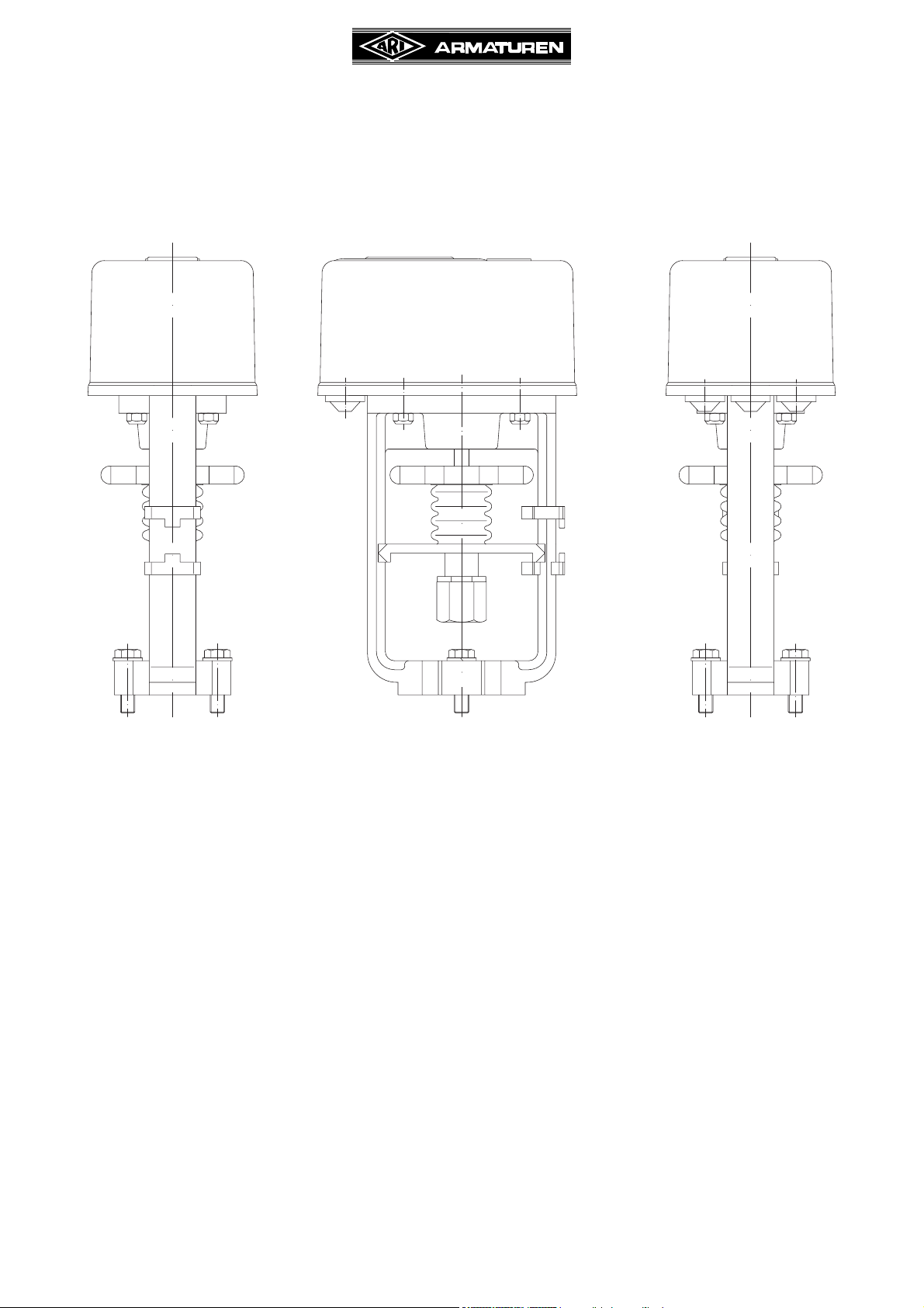
4.3 Diagram
4.3.1 ARI-PACO 0,85 kN
Operating and installation instructions
Electric thrust actuator ARI-PACO 0,85 kN
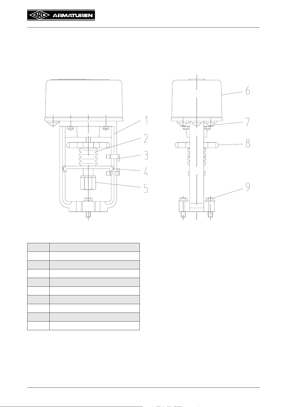
Fig. 1
4.3.1.1 Parts
Pos. Designation
1
2
3
4
5
6
7
8
9
Yoke
Bellow
Travel indicator
Torsion safety feature
Coupling
Hood
Cable conduit fitting
Handwheel
Hexagon-head screw M8
Page 6 0040506000 1811
Operating and installation instructions
Electric thrust actuator ARI-PACO 0,85 kN
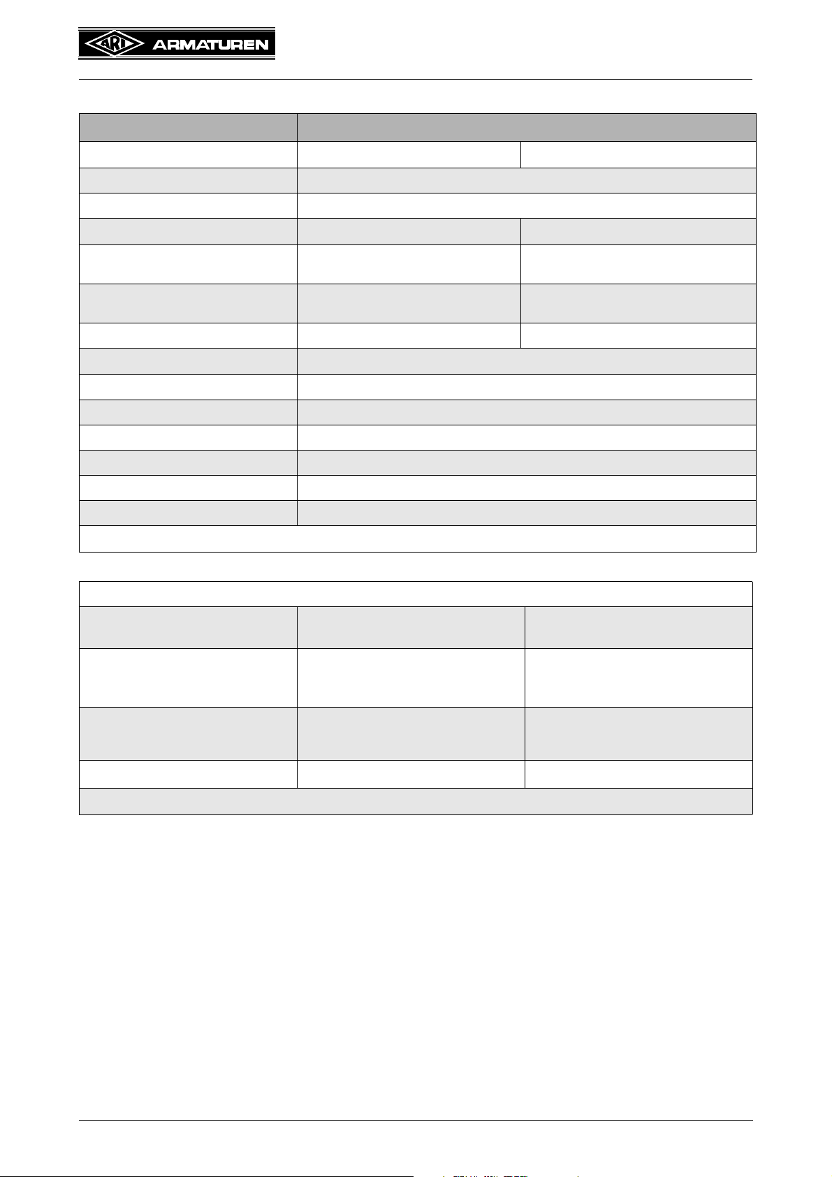
4.4 Technical data - Remarks
Type ARI-PACO
Thrust kN
Travel max. mm 3 ... 20
Control speed mm/sec. 0,11
Motor voltage ( ±10% )
Control signal (input) Three-step signal
Feedback signal (output) --
Power consumption VA 4,1 4,8
Operation mode
Enclosure IEC 60529 IP 54
Max. operative ambient temperature 0 °C ... +50 °C
Handwheel Change-over switch and handwheel
Mounting position Horizontally to vertical above the valve body (any position 90° from vertical)
Stem lubricant Klüber: Microlube GB
Weight kg 1,3
0,85 D 0,85 Y
230V - 50 / 60Hz* 24V - 50 / 60Hz*
0 (2) - 10 V DC
(invertable, max. 0,5 mA)
0 - 10 V DC
(invertable, max. 5 mA)
S3 50% cyclic duration factor
* Control speed and power consumption are 20% higher at frequency of 60 Hz.
Accessories
Additional torque switches
Switch board
(optional as 2 add. torque switches or
1 error message switch usable)
Potentiometer 1 pc. - 1000 Ohm
Additional voltages/frequencies
2 changeover contacts, potential-free,
switching capacity 3A, 250 V~
--
24 V 50/60* Hz
* Control speed and power consumption are 20% higher at frequency of 60 Hz.
--
2 changeover contacts, potential-free,
switching capacity 3A, 250 V~
1 pc. - 1000 Ohm
(alternative to
switch board)
--
0040506000 1811 Page 7
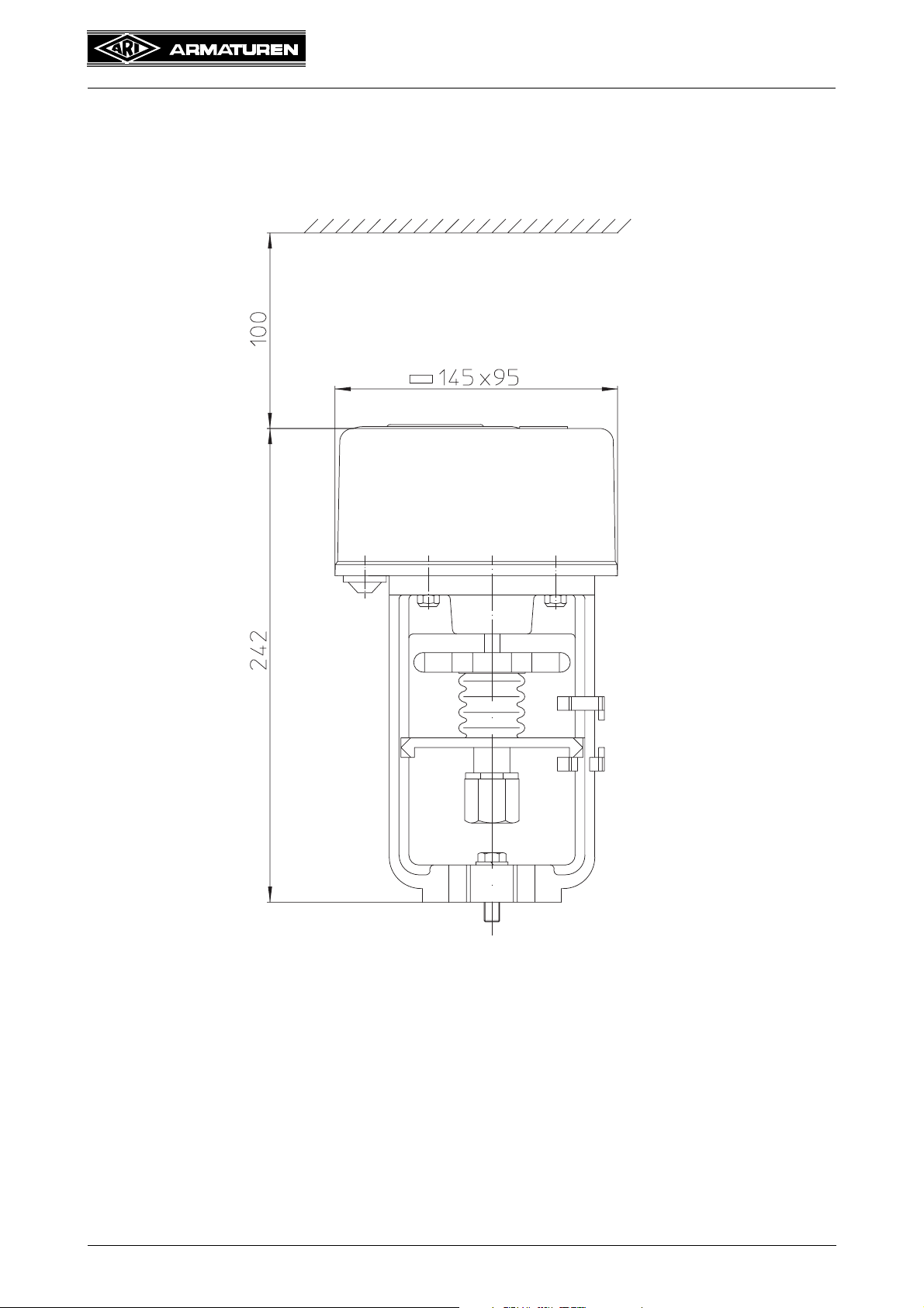
4.5 Dimensions
Operating and installation instructions
Electric thrust actuator ARI-PACO 0,85 kN
Clearance required for
removal of hood
Fig. 2
Page 8 0040506000 1811
Operating and installation instructions
Electric thrust actuator ARI-PACO 0,85 kN
5.0 Installation
ATTENTION !
- Work on electrical systems or equipment must only be carried out by qualified
electricians or by trained individuals under the guidance and supervision of a
qualified electrician in compliance with regional electrical safety requirements
and regulations.
- Valve mountings such as drives, handwheels, hoods must not be used to take
external forces, e.g. they are not designed for use as climbing aids, or as
connecting points for lifting gear.
Non-compliance may lead to death, injury or damage to property due to
persons falling or parts being dropped.
- Actuator components which rotate or move during operation.
Crushing and injury hazard!
5.1 General installation data
In addition to general installation guidelines, the following items are required to be
observed:
- Planners / construction firms and operators are responsible for positioning and installing
the products.
- Check thrust actuator for damage prior to fitting.
Damaged parts must be replaced by original spares.
- Existing operating instructions for valve.
- Complete valve with crossarm.
- Valve cone approximately in mid lift position - on no account supported inside a seat!
- Electrical installation in accordance with current regional regulations.
- Conductor cross-section selected to correspond to the given drive power and existing line
length.
- Mains fuse rating max. 6A.
- Circuit breakers in the plant to cut off the mains supply to the actuator.
- Conformity of technical data on thrust actuator with field conditions.
- Mains voltage in accordance with data specified on rating plate of thrust actuator.
- Thrust actuator complete with yoke or distance columns and coupling parts intended for
mounting to the corresponding valve.
- Ease of access to installation site.
- Adequate clearance space above the thrust actuator for removing the hood
(refer to item „4.5 Dimensions“).
- Install where there is protection against high-energy heat radiation.
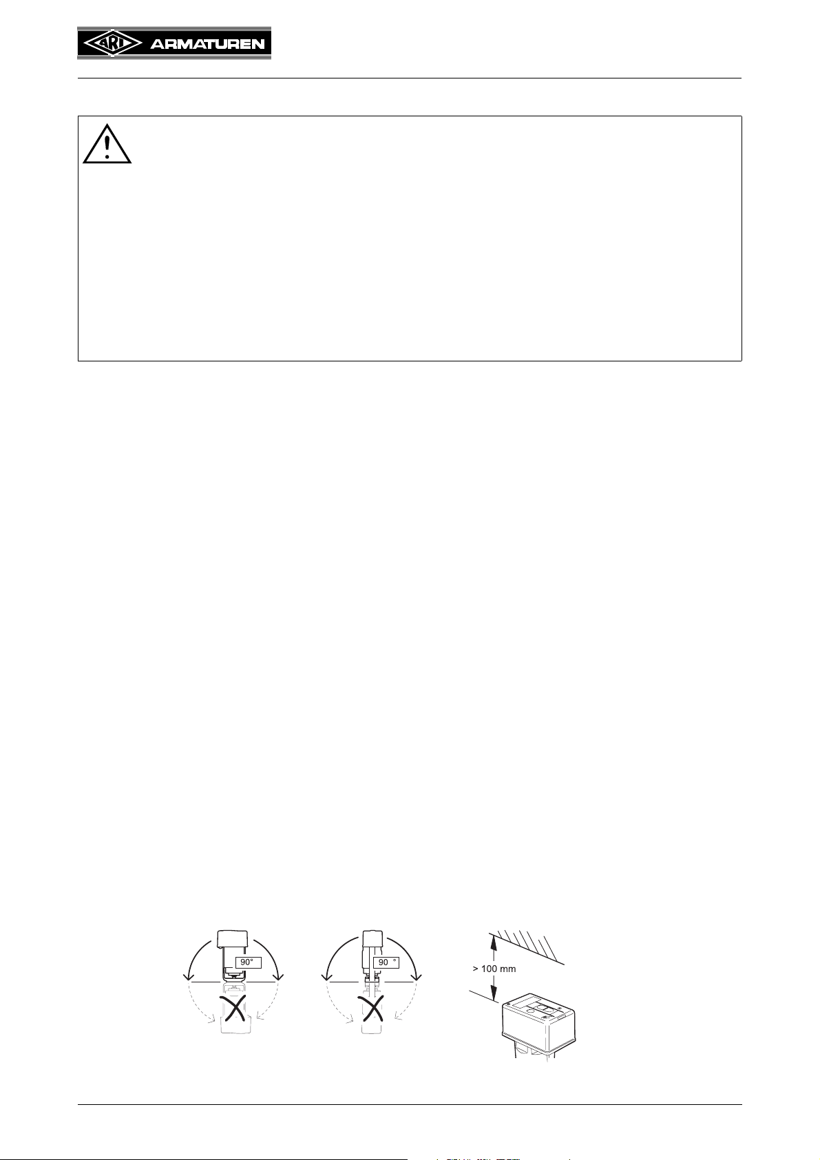
- The ambient temperature must not exceed +50 °C.
- Linear actuator installation orientation should be vertical above the valve up to a horizontal
position.
Fig. 3
0040506000 1811 Page 9

Operating and installation instructions
Electric thrust actuator ARI-PACO 0,85 kN
5.2 Manual operation
5.2.1 ARI-PACO 0,85 kN
ATTENTION !
- Since the hand wheel always turns during motor operation (running display),
never use manual operation when the motor is running - danger of injury!
For the manual operation, the sliding switch above the housing must be switched to
manual.
Automatic
Manual
Fig. 4
Proceed as follows:
- Turning clockwise --> coupling moves in
- Turning counter-clockwise --> coupling moves out
On reaching the end positions, a slip coupling prevents further actuating force.
Page 10 0040506000 1811
 Loading...