


Argos 171-8140, 145-0446, 157-3622, 170-9214, 160-9785 ASSEMBLY INSTRUCTIONS
...Seville - Bedside
Assembly Instructions - Please keep for future reference |
|
171/8140 |
|
|
|
|
|
170/9214 |
145/0446
157/3622
159/7732
160/9785
162/9325
162/7956
Dimensions
Width - 35.5cm
Depth - 33cm
Height - 41.5cm
MADE IN BRITAIN
Important - Please read these instructions fully before starting assembly
If you need help or have damaged or missing parts, call the Customer Helpline: 0870 112 1928 or email: Help@ClickSpares.co.uk (quoting your original order number)
Issue 2 - 12/12/13


 Safety and Care Advice
Important - Please read these instructions fully before starting assembly
•Warning: This unit weighs approximately 7kgs. Please lift with care.
•Check you have all the components and tools listed on pages 2 and 3.
•Remove all fittings from the plastic bags and separate them into their groups.
•Keep children and animals away from the work area, small parts could choke if swallowed.
•Parts of the assembly will be easier with 2 people.
•Make sure you have enough space to layout the parts before starting.
•Do not stand or put weight on the product, this could cause damage.
•Assemble the item as close to its final position (in the same room) as possible.
•Assemble on a soft level surface to avoid damaging the unit or your floor (use opened out unit carton).
• We do not recommend the
use of power
drill/drivers for inserting screws,
as this could damage the unit. Only use hand screwdrivers.
•Safety note: If there is any chance of this unit being pulled over by children etc. it is recommended that the unit is secured to a wall using suitable fixings (not supplied).
•Dispose of all packaging carefully and responsibly.
Care and maintenance
• Only clean using a damp cloth |
• From time to time check that |
• This product should not be |
and mild detergent, do no use |
there are no loose screws on |
discarded with household |
bleach or abrasive cleaners. |
this unit. |
waste. Take to your local |
|
|
authority waste disposal centre. |
|
|
|
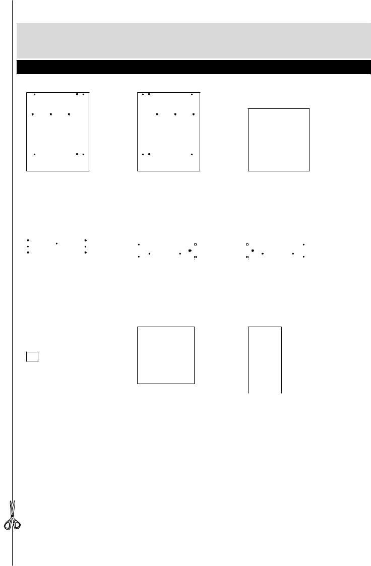
Note: If required the next page can be cut out and used as reference throughout the assembly. Keep this page with these instructions for future reference.
1
If you have damaged or missing components, call the
Components - Panels Customer Helpline: 0870 112 1928 or email: Help@ClickSpares.co.uk (quoting your original order number
and the reference numbers below)
Please check you have all the panels listed below
1 |
Left Side (D2494A) |
2 |
Right Side (D2495A) |
3 |
Top/Base (D2493A) |
|||||
|
(412 x 328mm) |
|
(412 x 328mm) |
|
(321 x 327mm) x 2 |
|||||
|
|
|
|
|
|
|
|
|
|
|
|
|
|
|
|
|
|
|
|
|
|
|
|
|
|
|
|
|
|
|
|
|
|
|
|
|
|
|
|
|
|
|
|
|
|
|
|
|
|
|
|
|
|
|
|
4 |
Drawer Front (D2496A) |
5 |
Left Drawer Side (W410LH) |
6 |
Right Drawer Side (W410RH) |
||
|
|
(317 x 157mm) |
|
(300 x 95mm) |
|
(300 x 95mm) |
||
|
|
|
|
|
|
|
|
|
|
|
|
|
|
|
|
|
|
|
|
|
|
|
|
|
|
|
|
|
|
|
|
|
|
|
|
|
|
|
|
|
|
|
|
|
7 Drawer Back (W288-95)
(288 x 95mm)
8 |
Drawer Base (T299-297) |
|
|
|
|
|
|
||
|
(299 x 297mm) |
9 |
Back (X175-347) |
|
|
|
|
(175 x 347mm) |
|
2
If you have damaged or missing components, call the
Components - Fittings Customer Helpline: 0870 112 1928 or email: Help@ClickSpares.co.uk (quoting your original order number
and the reference numbers below)
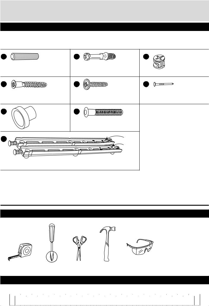
Please check you have all the fittings listed below
Note: The quantities below are the correct amount to complete the assembly. In some cases more fittings may be supplied than are required.
A |
|
B |
|
C |
Wooden dowel (F22) |
x 4 |
Metal dowel (F901) x 2 |
Small locking |
|
|
|
|
|
nut (F3) x 2 |
D |
|
E |
|
F |
40mm Screw (F910) |
x 8 |
25mm Screw (F95) |
x 1 |
Nail (F51) x 5 |
G |
|
H |
|
|
Handle (F300) x 1 |
Knock-in Peg (F171WH) |
x 4 |
||
I |
|
|
|
R (F601) |
F599 |
|
|
|
L (F600) |
|
|
|
|
|
F599 |
Drawer stops (F599) x 2 |
|
|
|
|
|
|
||
|
Runners (F600) x 1 and (F601) x 1 |
|
|
|
Tools required
|
Rule |
|
Cross-head |
|
Scissors |
Hammer |
|
Eye protection |
|
|
|
|
|||||
|
|
|
|
(when using a |
|
|
|
|
|||||||||
|
|
|
screwdriver |
|
|
|
|
|
|
hammer or drill) |
|
|
|
|
|||
Ruler - Use this ruler to help correctly identify the screws |
|
|
|
|
|
|
|||||||||||
mm |
10 |
20 |
30 |
40 |
50 |
60 |
70 |
80 |
90 |
100 |
110 |
120 |
130 |
140 |
150 |
160 |
170 |
3

If you have damaged or missing components, call the
Assembly Instructions Customer Helpline: 0870 112 1928 or email: Help@ClickSpares.co.uk (quoting your original order number
and the reference numbers below)
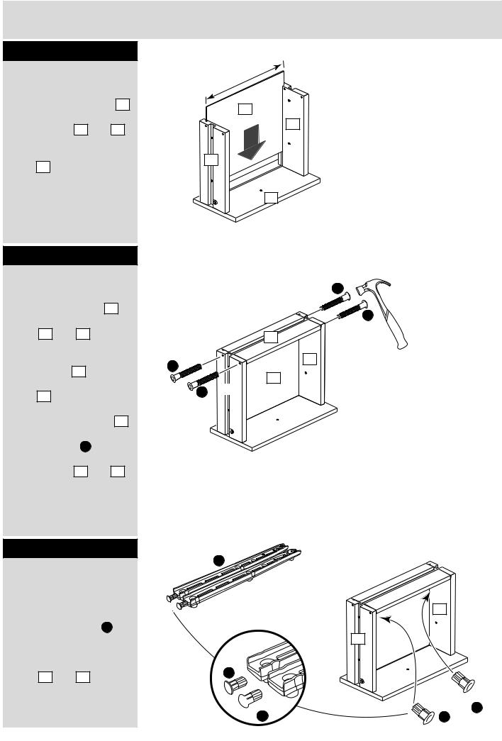
Step 1
Prepare the drawer front
Screw 2 metal dowels B into the holes shown on the back of the drawer front 4 .
Note: Tighten metal dowels up fully against the panels.
Step 2
Prepare the drawer sides
Insert a small locking nut C into the hole shown on the left drawer side 5 and right drawer side 6 .
Note: Arrow on locking nut must point towards hole in edge of panel.
Step 3
Attach the drawer sides to the drawer front
Push the left drawer side
. 5 and right drawer side
. 6 onto the back of the drawer front 4 .
Turn the small locking nuts C on the left
drawer side |
|
and right |
5 |
||
drawer side |
|
. |
6 |
Note: Turn the locking nuts C clockwise to secure panels - more than 1/2 a turn.
Plain chipboard surface
B
B 
B 
4
Note: Due to the manufacturing process, the holes for the locking nut can be on either surface of the drawer sides.
C |
|
C |
C |
5 |
6 |
Small groove
C
6
B |
5 |
|
4
Note: The locking nuts can be on either surface of the drawer sides. Make sure that the small groove is on the inside, as shown.
4
Assembly Instructions
Step 4
Fit the drawer base
Slide the drawer base 8 down the grooves in the drawer sides 5 and 6
and down into the groove in the drawer front 4 .
Step 5
Fit the drawer back
Fit the drawer back 7 between the drawer sides 5 and 6 .
Make sure that the drawer base 8 fits into
the groove in the drawer back 7 .
Hold the drawer back 7 in position and tap the knock-in pegs H through the holes in the drawer sides 5 and 6 .
299mm
8
6
5
4
H
|
7 |
H |
|
|
8 |
H |
5 |
|
Step 6
Push in drawer stops
Carefully break off the 2 drawer stops (F599) from
the drawer runners I .
Push the drawer stops fully through the drawer sides 5 and 6 from the inside.
I
SNAP!
SNAP!
5
F599
I
 F599
F599
I
F599
F599 I
I
5

Assembly Instructions
Step 7
Attach the handle
Attach the handle G to the drawer front 4 using screw E .
Step 8
Prepare the left side
Separate the runners I .
Push fit the left runner I marked ‘L’ into the left side 1 .
Note: Runners must be be fitted flat against the panel. If necessary gently tap into final position.
Step 9
Prepare the right side
Push fit the left runner I marked ‘R’ into the right side 2 .
Note: Runners must be be fitted flat against the panel. If necessary gently tap into final position.
E
G
4
L |
F600 |
Finished |
I |
|
|
|
|
|
I |
|
|
1
2 |
I |
R F601 |
|
|
I |
Finished front edge
6

Assembly Instructions
Step 10
Prepare the top and the base
Tap 2 wooden dowels |
A |
into the top 3 and the base 3 .
Step 11
Join the top to the right side
Push the top 3 onto the right side 2 and secure with 2 screws D .
A
x 2
Finished front edge
D
2
front edge
Plain chipboard surface
3
A
3
Finished front edge
Step 12
Join the base to the right side
Push the base 3 onto the right side 2 and
secure with 2 screws D .
D
D
3
Finished front edge
7

Assembly Instructions
Step 13
Fit the left side
Push the left side 1
onto the assembly and secure with 4 screws D .
 D
D
 D
D
1

 D
D
 D
D
Step 14
Fit the back
a:Square up the unit by making sure that measurement x to x equals y to y.
b:Place the back 9 onto the unit.
Nail F around the 3 edges of the back 9 as shown.
Stand the unit up for the next step.
a: The measurement from top corner X to bottom corner X must be equal to the measurement from top corner Y to bottom corner Y
b:
F |
|
x |
y |
9 |
y |
|
x |
8
Assembly Instructions
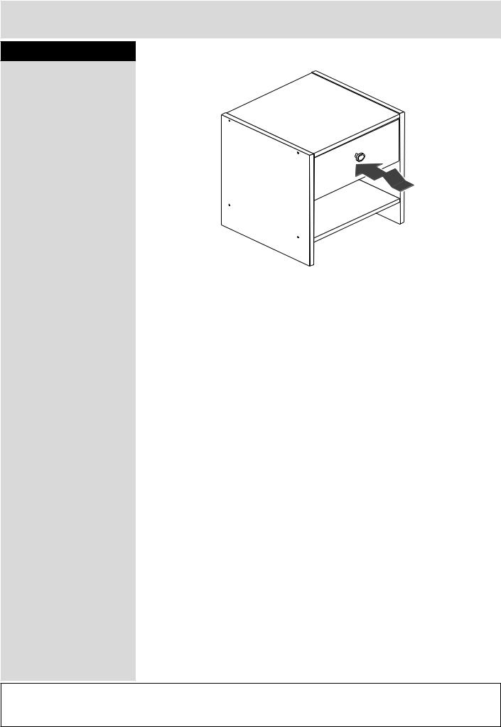
Step 15
Insert the drawer
Lift the front of the drawer whilst inserting to overcome the ‘stop’ system.
Note: To ensure that your drawer runs smoothly, spray a small amount of furniture polish into the grooves.
Assembly is complete
If you need help or have damaged or missing parts, call the Customer Helpline: 0870 112 1928 or email: Help@ClickSpares.co.uk (quoting your original order number and the reference numbers on the component pages)
Argos Ltd, 489-499 Avebury Boulevard, Central Milton Keynes, MK9 2NW
9
ALR2908
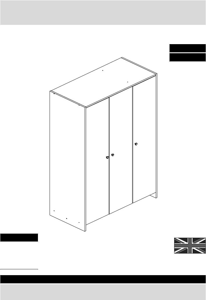
Seville - 3 Door Robe
Assembly Instructions - Please keep for future reference |
|
147/4556 |
|
|
|
|
|
171/6939 |
167/8338
173/6146
Dimensions
Width - 102.5cm
Depth - 49.5cm
Height - 175.5cm
MADE IN BRITAIN
Important - Please read these instructions fully before starting assembly
If you need help or have damaged or missing parts, call the Customer Helpline: 0870 112 1928 or email: Help@ClickSpares.co.uk (quoting your original order number)
Issue 2 - 04/09/13

 Safety and Care Advice
Important - Please read these instructions fully before starting assembly
•Warning: This unit weighs approximately 59kgs. Please lift with care.
•Check you have all the components and tools listed on pages 2 and 3.
•Remove all fittings from the plastic bags and separate them into their groups.
•Keep children and animals away from the work area, small parts could choke if swallowed.
•Parts of the assembly will be easier with 2 people.
•Make sure you have enough space to layout the parts before starting.
•Do not stand or put weight on the product, this could cause damage.
•Assemble the item as close to its final position (in the same room) as possible.
•Assemble on a soft level surface to avoid damaging the unit or your floor (use opened out unit carton).
• We do not recommend the
use of power
drill/drivers for inserting screws,
as this could damage the unit. Only use hand screwdrivers.
•Safety note: It is recommended that this unit is secured to a wall using the bracket supplied.
•Dispose of all packaging carefully and responsibly.
Care and maintenance
• Only clean using a damp cloth |
• From time to time check that |
• This product should not be |
and mild detergent, do no use |
there are no loose screws on |
discarded with household |
bleach or abrasive cleaners. |
this unit. |
waste. Take to your local |
|
|
authority waste disposal centre. |
|
|
|
Note: If required the next page can be cut out and used as reference throughout the assembly. Keep this page with these instructions for future reference.
1
If you have damaged or missing components, call the
Components - Panels Customer Helpline: 0870 112 1928 or email: Help@ClickSpares.co.uk (quoting your original order number
and the reference numbers below)
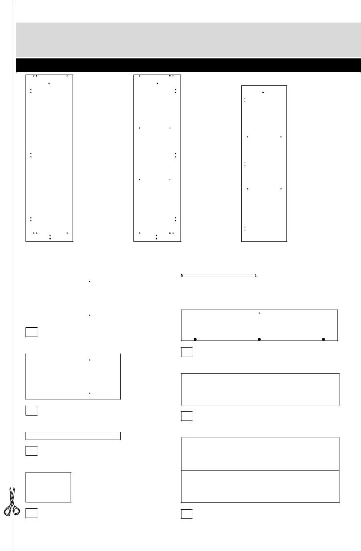
Please check you have all the panels listed below
1 |
Left Side (D2483A) |
2 |
Right Side (D2497A) |
3 |
|
Upright (D2500A) |
||||
|
(1753 x 496mm) |
|
(1753 x 496mm) |
|
|
(1640.5 x 477mm) |
||||
|
|
|
|
|
|
|
|
|
||
|
|
|
|
|
|
|
Hanging Rail (FHR659) |
|||
|
|
|
|
|
8 |
|||||
|
|
|
|
|
|
|
(659mm long) |
|
|
|
|
|
|
|
|
|
|
|
|
|
|
4 Top (D2498A)
(995 x 495mm)
9 Door (D2487A)
(1652 x 327mm) x 3
5 Base (D2499A)
(995 x 480mm)
6 Plinth (D2502A)
(995 x 80mm)
10 Small Back (X1666-332)
(1666 x 332mm)
7 Shelf (D2501A)
(313 x 475mm) x 2
11 Large Back (X1666-685)
(1666 x 685mm)
2

If you have damaged or missing components, call the
Components - Fittings Customer Helpline: 0870 112 1928 or email: Help@ClickSpares.co.uk (quoting your original order number
and the reference numbers below)
Please check you have all the fittings listed below
Note: The quantities below are the correct amount to complete the assembly. In some cases more fittings may be supplied than are required.
A |
|
|
|
B |
|
|
|
|
C |
|
|
Wooden dowel (F22) x 6 |
|
|
Nail (F51) |
x 36 |
|
|
|
40mm Screw (F910) |
x 14 |
|
|
D |
|
|
|
E |
|
|
|
|
F |
|
|
25mm Screw (F95) |
x 3 |
|
|
13mm Screw (F79) |
x 1 |
|
13mm Screw (F63) |
x 20 |
|
||
G |
|
|
|
H |
|
|
|
|
I |
|
|
|
Bracket (F327) |
x 1 |
|
|
|
Rail holder |
|
|
|
||
|
|
|
|
(F1014) |
x 2 |
Handle (F300) |
x 3 |
||||
|
|
|
|
|
|
|
|
|
|||
J |
|
|
|
K |
|
|
|
|
L |
|
|
Back holder (F276) |
x 5 |
|
|
Nail screw (F277) |
x 5 |
|
Shelf support (F121) |
x 8 |
|
||
*These can also be round |
|
|
|
|
|||||||
|
|
|
|
|
|
|
|
|
|
||
M |
|
|
|
|
|
|
|
|
|
|
|
|
Hinge plate |
|
|
|
|
x 9 |
|
|
|
||
|
(F523) |
x 9 |
|
|
|
|
|
|
|
|
|
Tools required |
|
|
|
|
Eye protection |
|
|
Spirit |
(when using a |
Cross-head |
|
level |
hammer or drill) |
screwdriver |
|
|
|
|
Electric drill |
Scissors |
|
Bradawl |
(only use |
|
when drilling |
||
|
|
|
into walls) |
Ruler - Use this ruler to help correctly identify the screws
mm |
10 |
20 |
30 |
40 |
50 |
60 |
70 |
80 |
90 |
100 |
110 |
120 |
130 |
140 |
150 |
160 |
170 |
3

If you have damaged or missing components, call the
Assembly Instructions Customer Helpline: 0870 112 1928 or email: Help@ClickSpares.co.uk (quoting your original order number
and the reference numbers below)
Step 1
Prepare the top and base
Tap 2 wooden dowels |
A |
||||
into the top |
|
|
. |
|
|
4 |
|
||||
Tap 2 wooden dowels |
A |
||||
into the base |
|
. |
|
||
5 |
|
||||
Note: Wooden dowels must not stick out from the edge by more than 10mm or they may damage other panels.
A
4
Finished 
front edge
A
A
plain
Finished  front edge
chipboard |
surface |
|
A
A
10mm


Step 2 |
|
F |
|
Prepare the upright |
|
H |
|
|
|
||
Push a rail holder H into |
|
M |
|
the upright 3 . Make |
|
||
|
|
||
sure that it is fitted |
|
|
|
straight, in line with the |
|
|
|
panel edges and then |
|
M |
|
secure with screw F . |
|
3 |
|
|
|
||
Fit 3 hinge plates M onto |
|
Finished |
|
M |
front edge |
||
the upright 3 , making |
|||
|
|
||
sure that the slot is |
|
|
|
facing towards the |
|
|
|
finished front edge. |
|
M |
|
|
|
4

Assembly Instructions
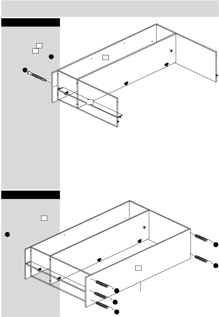
Step 3
Fit the top and the |
C |
base to the upright |
|
Fit the top 4 and the |
|
base 5 onto the upright |
|
. 3 using 4 screws C . |
|
|
4 |
|
3 |
C
 plain
plain
chipboard |
surface |
|
C
Finished front edge
Step 4
M
Prepare the right side
Fit 3 hinge plates M onto |
|
M |
the right side 2 , making |
|
|
|
|
|
sure that the slot is |
|
2 |
facing towards the |
|
|
|
|
|
finished front edge. |
M |
Finished |
|
|
|
|
|
front edge |
|
|
2 |
|
|
M |
5

Assembly Instructions
Step 5
Fit the right side
Push the right side 2 onto the top 4 and base 5 and secure it using 4 screws C .
C
C
Step 6
Prepare the plinth
Tap 2 wooden dowels |
A |
||
into the plinth |
|
. |
|
6 |
|
||
Step 7
Prepare the left side
Push a rail holder H into the left side 1 . Make sure that it is fitted straight, in line with the panel edges and then secure with screw F .
Fit 3 hinge plates M onto the left side 1 , making sure that the slot is facing towards the finished front edge.
C
2 |
4 |
5
A
Plain chipboard
6
A
|
|
F |
M |
M |
|
|
H |
|
|
Finished |
|
|
M |
|
M |
1 |
|
|
|
6
Assembly Instructions
Step 8
Fit the plinth
Push the plinth |
6 onto |
|
|
the right side 2 |
and |
|
|
secure it using screw |
C . |
2 |
|
C |
|
|
|


 6
6
Note: Support the plinth until the left side has been fitted in the next step.
Step 9
Fit the left side
Push the left side 1 onto the assembly and secure it using 5 screws
C
1

 C
C

 C
C

 C
C

 C
C

 C
C
7
Assembly Instructions
Step 10
Fit the back
a: Square up the unit by making sure that measurement x to x equals y to y.
Place the small back 10 and large back 11 down
onto the unit as shown.
Make sure that
the 2 backs are y pushed up tight against each
other and that they meet over the back edge of the upright.
b: Nail B around the outside edges of the 2 backs.
Note: Do not nail where the backs meet. Nails should be spaced about 150mm apart.
Step 11
Secure the backs
Tap the nail screws through the back
J and down between the backs 10 and 11 into the back edge
of the divider.
Keep tapping the nail screws K in until the back holders J dig into the small and large back.
Stand the unit up for the next step.
a: The measurement from top corner X to bottom corner X must be equal to the measurement from top corner Y to bottom corner Y
|
x |
Note: Do not |
|
nail where the |
|
|
|
|
|
|
backs meet. |
B |
|
|
10 |
|
y |
|
11 |
|
x
 K J
K J
J + K x 5 |
Note: These can |
also be round |
10
11
8
 Loading...