


Arecont Vision MDD-WMT, AV10655DN-08, AV10655DN-28, AV10655DN-NL, AV6655DN-08 Installation Manual
...MicroDome® Duo
Installation Manual
Models:
4 Megapixel
AV4655DN-08 AV4655DN-28 AV4655DN-NL
4 Megapixel WDR
AV4656 DN-08
AV4656DN -28
AV4656DN-NL
6 Megapixel
AV6655DN-08 AV6655DN-28 AV6655DN-NL
6 Megapixel WDR
AV6656DN-08
AV6656DN-28
AV6656DN-NL
10 Megapixel
AV10655DN-08 AV10655DN-28 AV10655DN-NL

Microdome Duo® |
Installation Manual |
Contents |
|
|
Models................................................................................................................................................... |
|
1 |
Package Content ................................................................................................................................... |
3 |
|
Warranty Information ............................................................................................................................. |
4 |
|
Camera Overview.................................................................................................................................. |
5 |
|
Surface Installation ................................................................................................................................ |
6 |
|
Drop Ceiling Mount Adapter Plate Installation........................................................................................ |
8 |
|
MDD-CAP Installation............................................................................................................................ |
9 |
|
MDD-CMT/WMT Pendant Mount and Wall Mount Installation............................................................... |
10 |
|
MDD-FMA Flush Mount Installation ...................................................................................................... |
11 |
|
Pan and Tilt Adjustment........................................................................................................................ |
14 |
|
Lens Replacement................................................................................................................................ |
15 |
|
Usage of Ethernet cable other than included M/F PoE cable. ............................................................... |
16 |
|
Connecting Digital I/O........................................................................................................................... |
17 |
|
AUX I/O use case example................................................................................................................... |
18 |
|
OUTPUT Relay Control and Function................................................................................................... |
19 |
|
INPUT Alarm Control and Detection ..................................................................................................... |
20 |
|
Camera Power Up using PoE ............................................................................................................... |
22 |
|
Use of Auxiliary Power.......................................................................................................................... |
23 |
|
Camera Discovery, Setup, and Configuration ....................................................................................... |
24 |
|
Network Protocols ................................................................................................................................ |
25 |
|
General Remote Focus......................................................................................................................... |
26 |
|
AV IP Utility Focus Tab......................................................................................................................... |
28 |
|
Administration and Password Setting ................................................................................................... |
29 |
|
Reset to Factory Default ....................................................................................................................... |
30 |
|
Troubleshooting.................................................................................................................................... |
31 |
|
Support................................................................................................................................................. |
|
32 |
Page | 2 |
support@arecontvision.com |
|
+1.818.937.0700 | 877.CAMERA.8 | www.arecontvision.com | avsales@arecontvision.com

Microdome Duo® |
Installation Manual |
CAUTION!
1.Do not attempt to service a damaged unit yourself. Refer all servicing to qualified service personnel.
2.Wiring methods shall be in accordance with the National Electrical Code/NFPA 70/ANSI, and with all local codes and authorities having jurisdiction. Wiring should be UL Listed and/or Recognized wire suitable for the application.
3.Always use hardware e.g. screws, anchors, bolts, locking nuts etc. which are compatible with mounting surface and of sufficient length and construction to insure a secure mount.
Package Content
This equipment should be unpacked and handled with care. The original packaging is the safest container in which to transport the unit and can be used if returning the unit for service. The packaging contains:
One (1) Arecont Vision Camera with Mounting Adapter Plate installed.
One (1) Drop Ceiling Mount Plate Adapter
One (1) I/O Cable
One (1) M-F CAT-5E Network Patch Cable with grommet (installed)
Blind Grommet
Standard Grommet
Grommet Insertion Tool
One (1) Security L-key
One (1) CD with Manual and Software
One (1) Mounting Template (Drop Ceiling/Surface Mount)
Four (4) Mounting Screws (#6x1” for wood or sheet metal)
Four (4) Mounting Dry Wall Anchors
Four (4) Ceiling Mount Mounting Screws #6-32 PPH UNC 1.0” LG.
Four (4) Box Mount Mounting Screws #8-32 UNC PTH 0.5” LG. (Low profile head)
One (1) Flat-head screwdriver
One (1) Philips head screwdriver
Page | 3 support@arecontvision.com
+1.818.937.0700 | 877.CAMERA.8 | www.arecontvision.com | avsales@arecontvision.com

Microdome Duo®
Installation Manual
Warranty Information
Global (3 Year) Limited Warranty
ARECONT VISION warrants to Purchaser (and only Purchaser) (the “Limited Warranty”), that: (a) each
Product shall be free from material defects in material and workmanship for a period of thirty-six (36) months from the date of shipment (the “Warranty Period”); (b) during the Warranty Period, the Products will materially conform with the specification in the applicable documentation; (c) all licensed programs accompanying the
Product (the “Licensed Programs”) will materially conform with applicable specifications. Notwithstanding the preceding provisions, ARECONT VISION shall have no obligation or responsibility with respect to any Product that (i) has been modified or altered without ARECONT VISION’s written authorization; (ii) has not been used in accordance with applicable documentation; (iii) has been subjected to unusual stress, neglect, misuse, abuse, improper storage, testing or connection; or unauthorized repair; or (iv) is no longer covered under the Warranty Period. ARECONT VISION MAKE NO WARRANTIES OR CONDITIONS, EXPRESS, IMPLIED, STATUTORY OR OTHERWISE, OTHER THAN THE EXPRESS LIMITED WARRANTIES MADE BY ARECONT VISION ABOVE, AND ARECONT VISION HEREBY SPECIFICALLY DISCLAIMS ALL OTHER EXPRESS, STATUTORY AND IMPLIED WARRANTIES AND CONDITIONS, INCLUDING THE IMPLIED WARRANTIES OF MERCHANTABILITY, FITNESS FOR A PARTICULAR PURPOSE, NON-INFRINGEMENT AND THE IMPLIED CONDITION OF SATISFACTORY QUALITY. ALL LICENSED PROGRAMS ARE
LICENSED ON AN “AS IS” BASIS WITHOUT WARRANTY. ARECONT VISION DOES NOT WARRANT THAT
(I) THE OPERATION OF THE PRODUCTS OR PARTS WILL BE UNINTERRUPTED OR ERROR FREE; (II)
THE PRODUCTS OR PARTS AND DOCUMENTATION WILL MEET THE END USERS’ REQUIREMENTS;
(III) THE PRODUCTS OR PARTS WILL OPERATE IN COMBINATIONS AND CONFIGURATIONS SELECTED BY THE END USER; OTHER THAN COMBINATIONS AND CONFIGURATIONS WITH PARTS OR OTHER PRODUCTS AUTHORIZED BY ARECONT VISION OR (IV) THAT ALL LICENSED PROGRAM ERRORS WILL BE CORRECTED.
For RMA and Advance Replacement information visit http://www.arecontvision.com
Page | 4 support@arecontvision.com
+1.818.937.0700 | 877.CAMERA.8 | www.arecontvision.com | avsales@arecontvision.com

Microdome Duo®
Installation Manual
Camera Overview
The MicroDome Duo multi-sensor, multi-megapixel 2-dome cameras provide users with professional surveillance experience for a variety of network surveillance requirements.
The MicroDome Duo multi-megapixel cameras series feature a choice of 4-, 6- or 10-megapixel resolution options, including 4- and 6-megapixel WDR options.
These remote focus true day/night cameras are available with a choice of lenses including 2.8mm, 8mm or no lens options.
For added flexibility, users can place both individual three-axis lens gimbals independently in any direction These cameras are ideal for indoor and outdoor use and deliver excellent low light imaging.
Regardless of time-of-day, this camera is ideal for applications with challenging lighting conditions. The series combines a day/night mechanical IR cut filter for the highest image quality at any time of day. For applications with bright or over saturated lighting conditions, optional wide dynamic range delivers up to 100dB at full resolution and is available on select 4 and 6MP models. For applications with poor low lighting conditions, Binning Mode increases the camera’s low light performance by combining pixels so that more light can be collected.
MicroDome Duo cameras are designed for demanding environments. They are rated IP 66 for dust and water ingress protection and rated IK-10 for vandal resistance.
The cameras offer advanced streaming capabilities and is designed on an efficient H.264 encoding platform capable of delivering high quality video without straining the network. Power can be supplied via a single Power-over-Ethernet compliant network cable or with power from a 12-48V DC/24V AC power supply.
The camera's interface allows for an intuitive, fast, and easy configuration; while the Free AV IP Utility tool allows users to quickly configure multiple cameras at one time. The MicroDome Duo is PSIA (Physical Security Interoperability Alliance) compliant, providing interoperability between network video products regardless of manufacturer.
Page | 5 support@arecontvision.com
+1.818.937.0700 | 877.CAMERA.8 | www.arecontvision.com | avsales@arecontvision.com

Microdome Duo®
Installation Manual
Surface Installation
1.Determine a secure location to mount the camera.
2.Use the supplied security L-key, to loosen the four (4) screws which secure the cover.
 PIC. 1
3.Remove the cover. Do not remove screws from the dome cover.
4.Use Phillips screwdriver to loosen the four (4) screws securing the camera to adapter plate.
PIC. 2 (some parts removed for clarity)
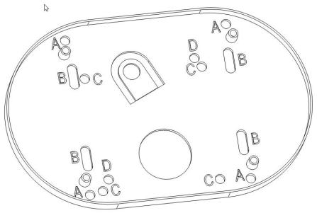
5.Separate Camera from Adapter Plate Do not remove the screws.
6.Use Surface Mount template and cable location to create mounting provisions for the camera.
7.Mount Adapter Plate by installing mounting hardware in 4 slots “B” in adapter plate
Page | 6 support@arecontvision.com
+1.818.937.0700 | 877.CAMERA.8 | www.arecontvision.com | avsales@arecontvision.com

Microdome Duo® |
Installation Manual |
 PIC. 3
PIC 4
8.Re-attach camera to adapter plate (Reverse step 4 and 5)
9.Re-attach cover to camera (Reverse step 2 and 3)
Page | 7 support@arecontvision.com
+1.818.937.0700 | 877.CAMERA.8 | www.arecontvision.com | avsales@arecontvision.com
Microdome Duo® |
Installation Manual |
Drop Ceiling Mount Adapter Plate Installation
Repeat step 1-5 of Surface Installation (See Pic. 1-3)
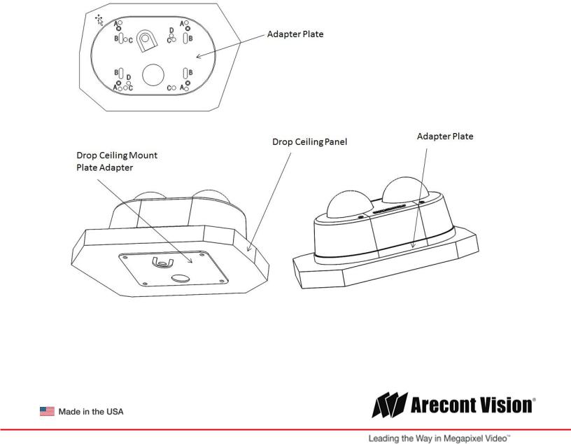
6.Use template and cable location to create mounting provisions for the Plate. Use 3/16” drill bits for four mounting holes in Drop Ceiling Panel.
7.Using enclosed #6-32 screws attach enclosed Drop Ceiling Mount Plate Adapter and Adapter Plate onto opposite sides of Drop Ceiling Panel, so the panel is “sandwiched” between Adapter Plate and
Drop Ceiling Mount Plate Adapter. Use 4 slots “B” in Adapter Plate.
8.Re-attach camera to adapter plate (Reverse step 4 and 5)
9.Re-attach cover to camera (Reverse step 2 and 3)
10.Re-install the Drop Ceiling Panel and plug Customer Ethernet cable into female end of Camera Ethernet cable.
PIC. 5
Page | 8 support@arecontvision.com
+1.818.937.0700 | 877.CAMERA.8 | www.arecontvision.com | avsales@arecontvision.com

Microdome Duo®
Installation Manual
MDD-CAP Installation
Repeat step 1-5 of Surface Installation (See Pic. 1-3)
6. Insert Adapter Plate into the Cap and attach it to the cap, using the 4 screws through 4 “A” holes using enclosed #6-32 screws.
Adapter Plate Cap
 PIC 6.
7.Re-attach camera to adapter plate (Reverse step 4 and 5)
8.Re-attach cover to camera (Reverse step 2 and 3)
PIC. 7
Page | 9 support@arecontvision.com
+1.818.937.0700 | 877.CAMERA.8 | www.arecontvision.com | avsales@arecontvision.com
Microdome Duo® |
Installation Manual |
MDD-CMT/WMT Pendant Mount and Wall Mount Installation
Assembly (Pic. 7) can be used with wall mount or ceiling mount
 PIC 8
PIC 8
PIC. 9
Use MCD-CMT and MCD-WMT installation instructions for reference.
Page | 10 support@arecontvision.com
+1.818.937.0700 | 877.CAMERA.8 | www.arecontvision.com | avsales@arecontvision.com
 Loading...