


AV1555DN-S
Arecont Vision AV1555DN-S, AV1555DN-S-NL, AV1555DNIR-S, AV1555DNIR-S-NL, AV2555DN-S Installation Manual
...
MicroDome®!G2
-S Model Installation Manual!
Models:
1.2 Megapixel
• AV1555DN-S
• AV1555DN-S-NL
1080p
• AV2555DN-S
• AV2556DN-S
• AV2555DN-S-NL
• AV2556DN-S-NL
3 Megapixel
• AV3555DN-S
• AV3556DN-S
• AV3555DN-S-NL
• AV3556DN-S-NL
5 Megapixel
• AV5555DN-S
• AV555DN-S-NL

!! ! Installation!Manual!
Page | 2 support@arecontvision.com
!
!
+1.818.937.0700 877.CAMERA.8 www.arecontvision.com avsales@arecontvision.com
MicroDome®!G2
!
Contents
!
Package Contents!..................................................................................................................................................!3!
Camera Overview!...................................................................................................................................................!5!
Surface Mount (-S Model) Installation!.................................................................................................................!6!
Changing the Lens!...............................................................................................................................................!12!
Optional: Removing the Bubble!..........................................................................................................................!13!
Optional: Connecting Digital I/O!.........................................................................................................................!14!
Camera Discovery, Setup, and Configuration!..................................................................................................!18!
Network Protocols!................................................................................................................................................!18!
General Remote Focus!.......................................................................................................................................!19!
Refined Remote Focus!........................................................................................................................................!20!
AV IP Utility Focus Tab!........................................................................................................................................!22!
Wall Mount Accessory (MCD-WMT)!..................................................................................................................!23!
Pendant Mount Accessory (MCD-CMT)!...........................................................................................................!24!
Mounting Template: MicroDome
®
G2 Camera!.................................................................................................!25!
Mount Template: MicroDome
®
MCD-WMT Wall Mount!..................................................................................!26!
Mount Template: MicroDome
®
MCD-CMT Pendant Mount!...........................................................................!27!
Support!..................................................................................................................................................................!28!
!
!
!! ! Installation!Manual!
Page | 3 support@arecontvision.com
!
!
+1.818.937.0700 877.CAMERA.8 www.arecontvision.com avsales@arecontvision.com
MicroDome®!G2
&
CAUTION!
1. Do not attempt to service a damaged unit yourself. Refer all servicing to qualified service
personnel.
2. Wiring methods shall be in accordance with the National Electrical Code/NFPA 70/ANSI, and
with all local codes and authorities having jurisdiction. Wiring should be UL Listed and/or
Recognized wire suitable for the application.
3. Always use hardware e.g. screws, anchors, bolts, locking nuts etc. which are compatible with
mounting surface and of sufficient length and construction to insure a secure mount.
Package Contents
This equipment should be unpacked and handled with care. The original packaging is the safest
container in which to transport the unit and can be used if returning the unit for service. The packaging
contains:
• One (1) Arecont Vision MicroDome® G2 Camera
• One (1) ceiling template
• One (1) CD containing software and user manual (license key required for recording)
• One (1) 4-position external power plug
• 6x Mounting Screws (#6x1” for wood or sheet metal)
• 6x Mounting Anchors
• 3/8” NPT Male to 1/2” NPT Female Adapter
• Network Patch Cable
• 3x Security Torx Dome Cover Fasteners
• One (1) Flat-head screwdriver
• One (1) Philips head screwdriver
• One (1) Gasket
!
!
!

!! ! Installation!Manual!
Page | 4 support@arecontvision.com
!
!
+1.818.937.0700 877.CAMERA.8 www.arecontvision.com avsales@arecontvision.com
MicroDome®!G2
!
Warranty Information
Global (3 Year) Limited Warranty
ARECONT VISION warrants to Purchaser (and only Purchaser) (the “Limited Warranty”), that: (a) each
Product shall be free from material defects in material and workmanship for a period of thirty-six (36)
months from the date of shipment (the “Warranty Period”); (b) during the Warranty Period, the
Products will materially conform with the specification in the applicable documentation; (c) all licensed
programs accompanying the Product (the “Licensed Programs”) will materially conform with applicable
specifications. Notwithstanding the preceding provisions, ARECONT VISION shall have no obligation or
responsibility with respect to any Product that (i) has been modified or altered without ARECONT
VISION’s written authorization; (ii) has not been used in accordance with applicable documentation; (iii)
has been subjected to unusual stress, neglect, misuse, abuse, improper storage, testing or connection;
or unauthorized repair; or (iv) is no longer covered under the Warranty Period. ARECONT VISION
MAKE NO WARRANTIES OR CONDITIONS, EXPRESS, IMPLIED, STATUTORY OR OTHERWISE,
OTHER THAN THE EXPRESS LIMITED WARRANTIES MADE BY ARECONT VISION ABOVE, AND
ARECONT VISION HEREBY SPECIFICALLY DISCLAIMS ALL OTHER EXPRESS, STATUTORY AND
IMPLIED WARRANTIES AND CONDITIONS, INCLUDING THE IMPLIED WARRANTIES OF
MERCHANTABILITY, FITNESS FOR A PARTICULAR PURPOSE, NON-INFRINGEMENT AND THE
IMPLIED CONDITION OF SATISFACTORY QUALITY. ALL LICENSED PROGRAMS ARE LICENSED
ON AN “AS IS” BASIS WITHOUT WARRANTY. ARECONT VISION DOES NOT WARRANT THAT (I)
THE OPERATION OF THE PRODUCTS OR PARTS WILL BE UNINTERRUPTED OR ERROR FREE;
(II) THE PRODUCTS OR PARTS AND DOCUMENTATION WILL MEET THE END USERS’
REQUIREMENTS; (III) THE PRODUCTS OR PARTS WILL OPERATE IN COMBINATIONS AND
CONFIGURATIONS SELECTED BY THE END USER; OTHER THAN COMBINATIONS AND
CONFIGURATIONS WITH PARTS OR OTHER PRODUCTS AUTHORIZED BY ARECONT VISION
OR (IV) THAT ALL LICENSED PROGRAM ERRORS WILL BE CORRECTED.
For RMA and Advance Replacement information visit http://www.arecontvision.com
!

!! ! Installation!Manual!
Page | 5 support@arecontvision.com
!
!
+1.818.937.0700 877.CAMERA.8 www.arecontvision.com avsales@arecontvision.com
MicroDome®!G2
Camera Overview
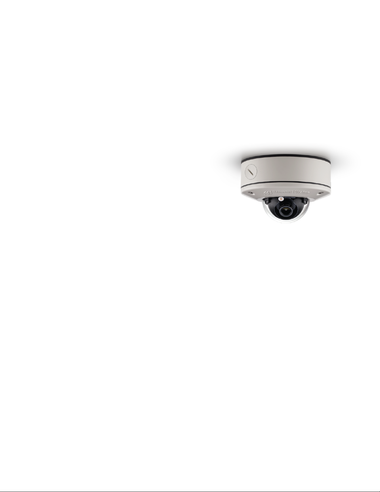
The MicroDome® G2 megapixel IP cameras provide professional surveillance for a variety of network
surveillance requirements. These remote focus true day/night cameras are available with a choice of
lenses including 2.8mm, 4mm, 6mm, 8mm, 12mm, and 16mm options. The 3-axis adjustment cameras
are available in 1.2MP, 1080p, 3MP and 5MP versions and are available in both recessed and surface
mount configurations. The –S model cameras are ideal for indoor or outdoor use and deliver excellent
low light imaging. Cast-aluminum housings combined with the polycarbonate bubble are vandal
resistant IK-10. The -S model MicroDome® G2 camera is rated IP66 and is protected against water and
dust. Add optional True Wide Dynamic Range (WDR) and difficult lighting conditions are overcome with
the MicroDome® G2.
!! ! Installation!Manual!
Page | 6 support@arecontvision.com
!
!
+1.818.937.0700 877.CAMERA.8 www.arecontvision.com avsales@arecontvision.com
MicroDome®!G2
Surface Mount (-S Model) Installation
1. Determine a secure location to mount the camera.
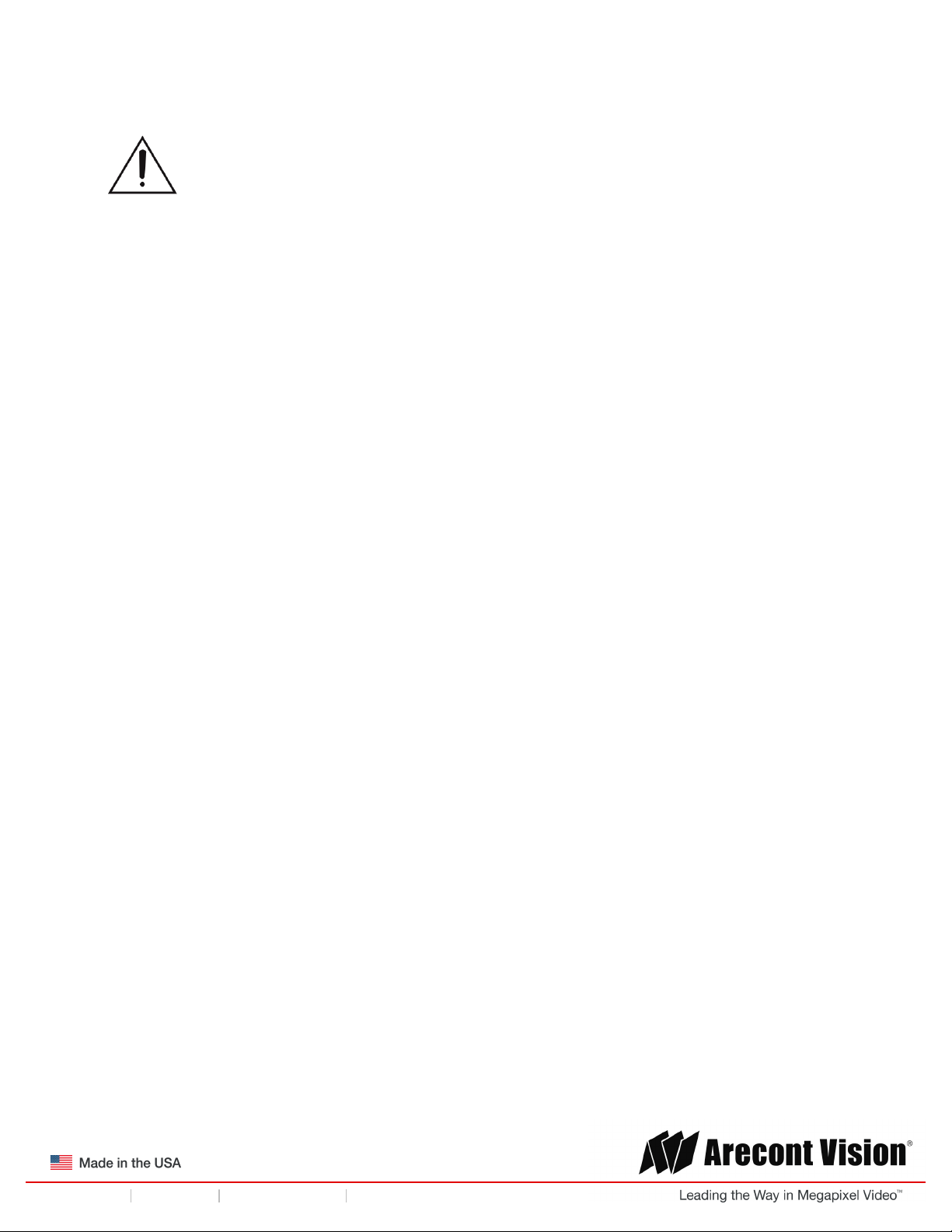
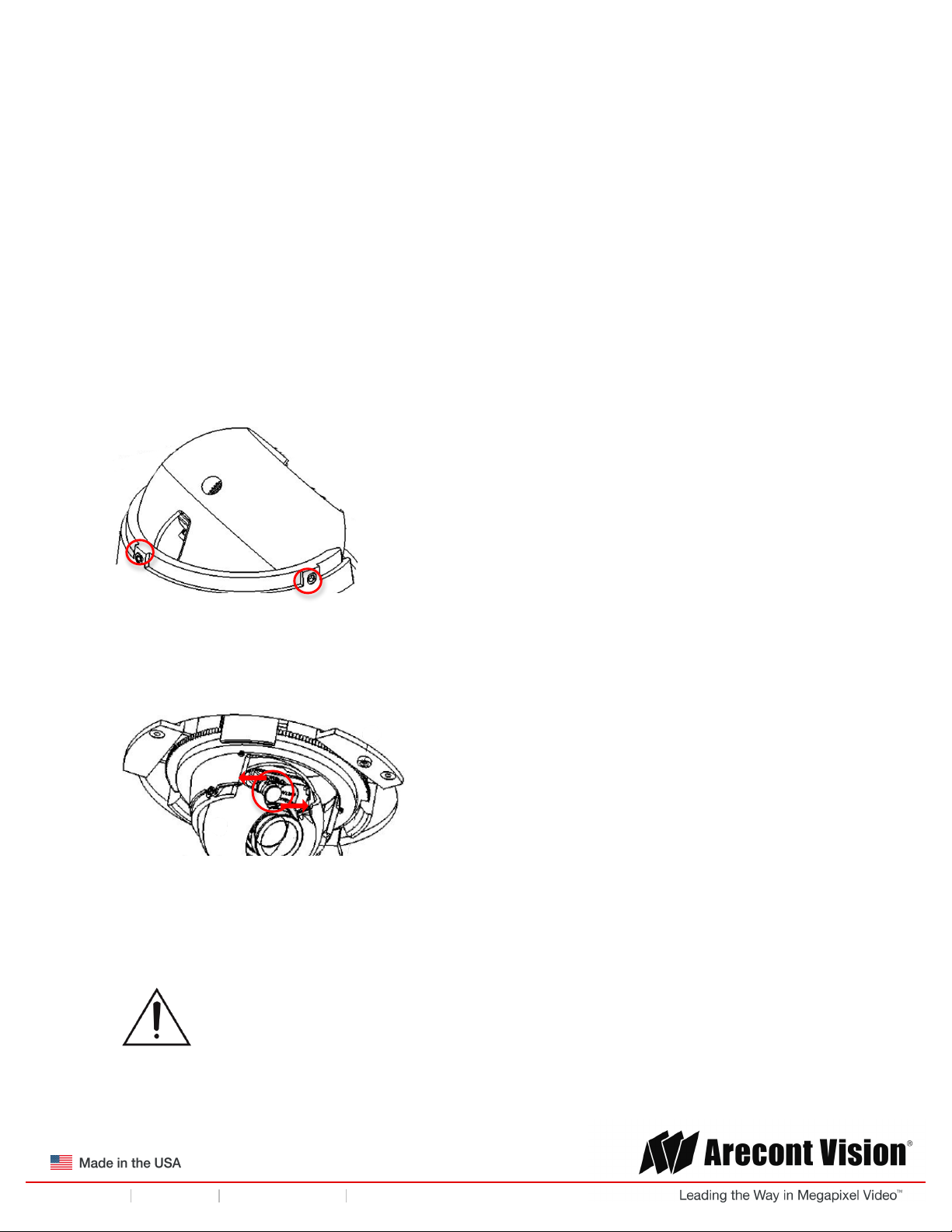
2. Remove the dome cover from the camera by unscrewing the three captive fasteners.
Figure 1: Remove dome cover
3. If required, the lens may be further secured by tightening the three lens lock screws using the
supplied flat-head screwdriver. Do not over torque the screws.
Figure 2: Optional: further tighten three lens lock screws
4. The camera can be mounted two ways: surface mount or via a junction box to a wall or ceiling.
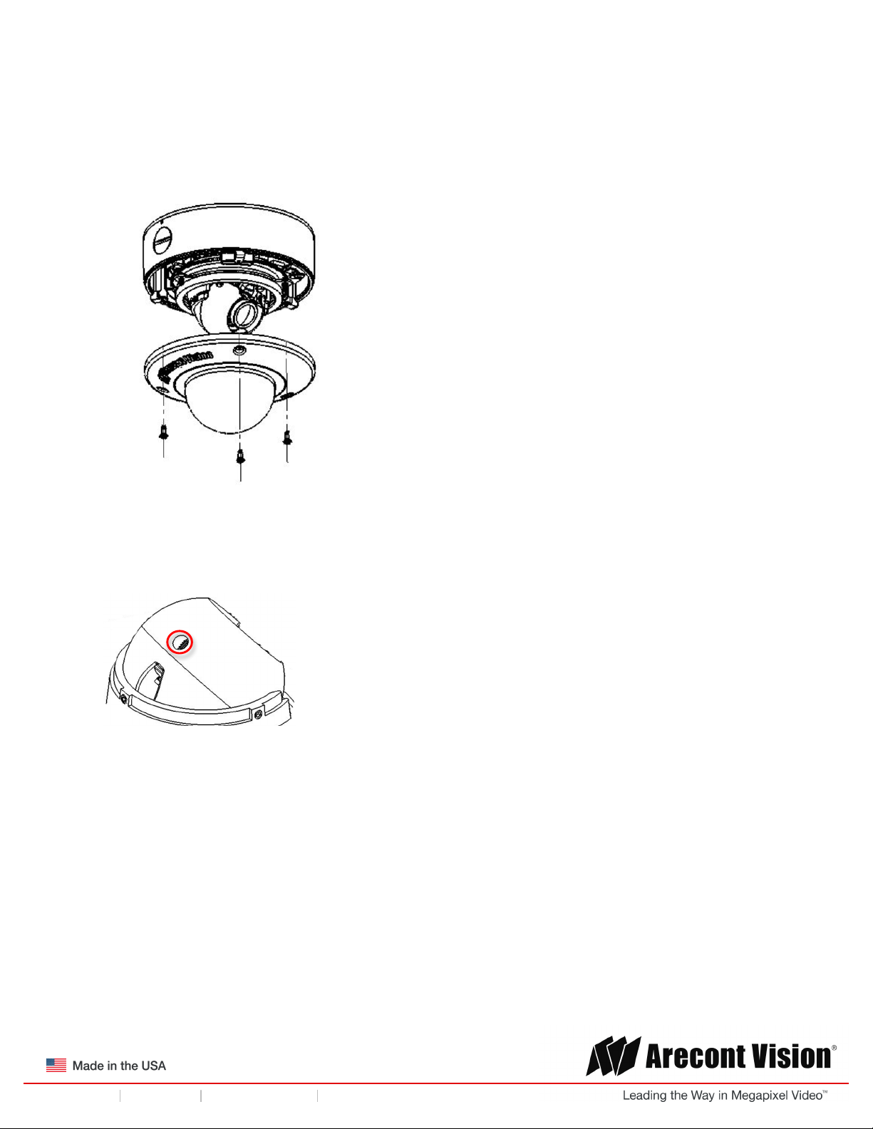
Choose the best method for your installation below:
a. Surface Mount: use the supplied template to mark three desired holes (there are six
holes to choose from; see Figure 3). Then drill the holes with a diameter of 8 mm (0.3 in)
and insert the supplied anchors into the holes. Attach the camera module and supplied
gasket securely using the supplied screws.
!! ! Installation!Manual!
Page | 7 support@arecontvision.com
!
!
+1.818.937.0700 877.CAMERA.8 www.arecontvision.com avsales@arecontvision.com
MicroDome®!G2
Figure 3: Drill three of the six holes provided.
NOTE: For installations in harsh environments, it is recommended to use all six mounting screws
supplied with the camera to create the best seal possible between the camera and the mounting
surface and using the supplied gasket.
-or-
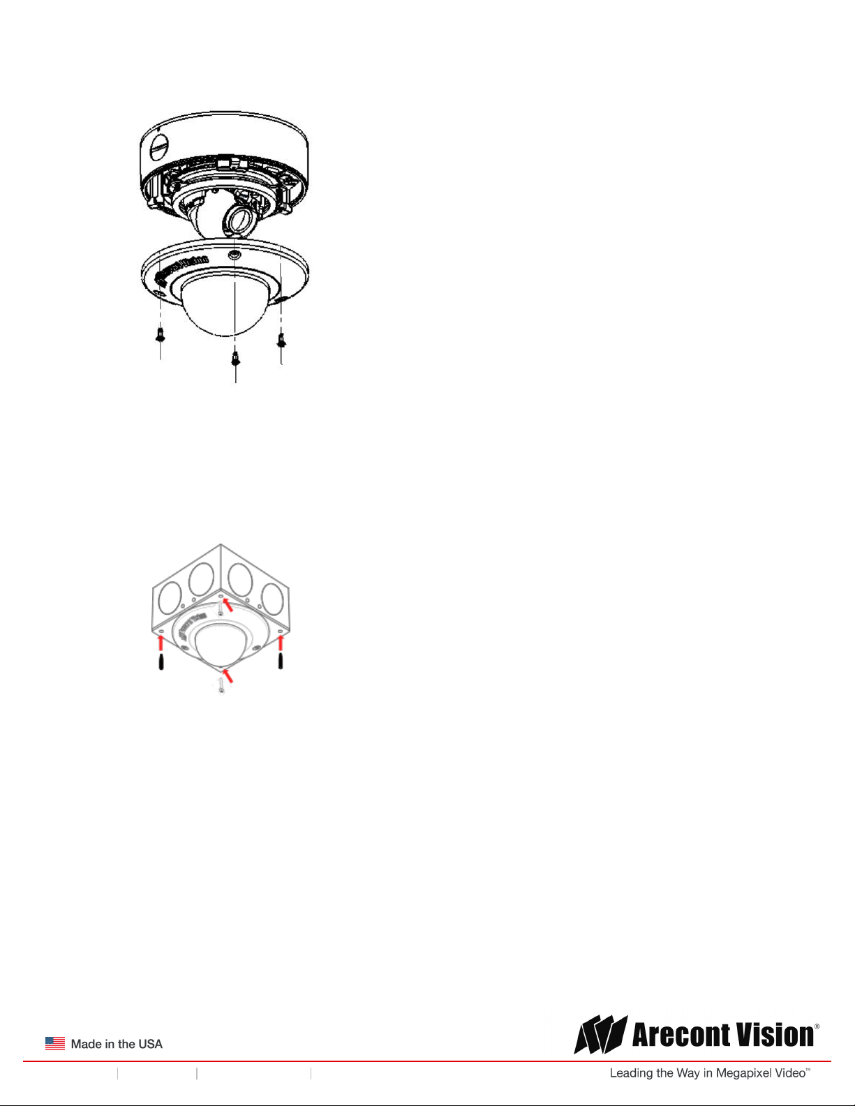
b. Junction Box: install a 4 in. gang box or square metal junction box (not supplied; Figure
4). NOTE: ensure openings for cables are accounted for prior to installation.
Figure 4: Install 4S junction box (not supplied)
c. Insert the supplied gasket inside the gang box.
d. Insert the camera flush against the gasket inside the 4S gang box; this will be a tight fit.
!! ! Installation!Manual!
Page | 8 support@arecontvision.com
!
!
+1.818.937.0700 877.CAMERA.8 www.arecontvision.com avsales@arecontvision.com
MicroDome®!G2
NOTE: If you use the side connection of the NPT port, remove the cap covering the side entrance,
otherwise; leave the cap in place. If using the NPT port, always use Teflon tape around the threads to
ensure proper sealing.
5. Route the cable tree from the camera around the rear of the camera module and secure all
cables. See the Connections section for details on how to connect the camera.
6. Check that the indicator LED’s are illuminated to the desired conditions (see LED Indicator
table).
7. Adjust the pan and tilt to obtain the desired field of view. Then, lock the camera head in place by
tightening at least two of the three set-screws with the supplied flat-head screwdriver (Figure 5).
Do not over torque the screws.
!
Figure 5: Lock camera head after adjusting the field of view
NOTE: Ensure not to press the remote focus motor against the sides of the camera module when
adjusting the field of view (Figure 5).
Figure 5: Remote focus motor
8. Install the dome cover by aligning the captive fasteners on the camera housing. If installing
inside a 4S junction box, the MCD-4S accessory dome cover plate (sold separately) is required.
CAUTION! The captive fasteners must be used to properly secure the dome cover. Failure
to use the captive fastener may result in serious injury. When mounting the dome cover to
the camera housing, ensure that the gasket is properly seated and not folded. Failure to
do so may result in water and dust ingress.
!! ! Installation!Manual!
Page | 9 support@arecontvision.com
!
!
+1.818.937.0700 877.CAMERA.8 www.arecontvision.com avsales@arecontvision.com
MicroDome®!G2
Figure 6: Attach dome cover with captive fasteners
9. If using the MCD-4S accessory plate, tighten the two captive fasteners with the supplied Philips
head screwdriver to secure the dome cover to the user supplied 4S junction box. Tightly insert
the two black plugs supplied with the MCD-4S for the remaining open holes. Cut any excess off
the rubber plugs, flush against the dome cover, with a utility knife.
Figure 7: Attach the MCD-4S accessory plate to the user supplied 4S junction box
NOTE: The supplied security torx screws may also be used.
 Loading...