

Page 1
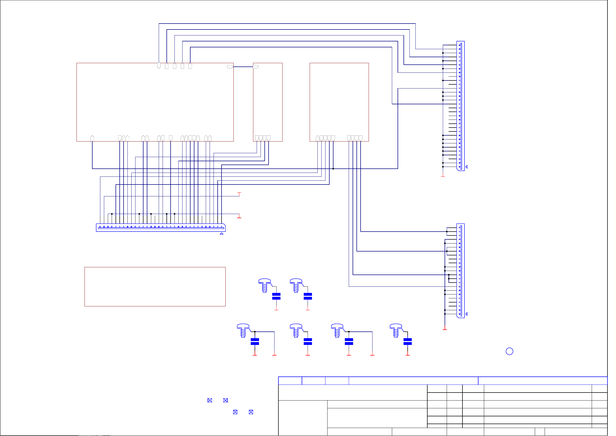
CD Interface
CD Interface.Sch
~XRST
SQSO
SQCK
XLAT
CLOK
Called MECH_CLOCK on 10DAC
CON500
32
DAC_CLK
RC5 in & Digital out
RC5 in & Digital out.Sch
SPDIF
EMPH
DAC_CLK
SCLK_MECH
DATA
SCLK
SENS
SDATA_MECH
SCOR
LRCLK_MECH
LOAD
UNLD
DISCO
DI/SWRW1/2X
SYSM
TRIGSW
TRIGIN
RMLEDRMLED+
~XRST
~STANDBY
VfilA
VfilB
-30V
+5VD
SPDIF
TRIGIN
TRIGSW
RMLED+
RMLED-
PSUsection
PSUsection.Sch
VfilA
VfilB
~STANDBY
-30V
+18VU_SW
-18VU_SW
DAC_RELAY
~XRST
+5VDAC_SW
SCLK_MECH
SDATA_MECH
LRCLK_MECH
~XRST
EMPH
THIS CONNECTOR REVERSED
AT OTHER END OF FOIL
31
30
29
28
27
26
25
24
23
22
21
20
19
18
17
16
15
14
13
12
11
10
9
8
7
6
5
4
3
2
1
DGND
Flexfoil to 10DAC
MOLEX
52045
31
32
CON501
MOLEX
52045
SQSO
SQCK
XLAT
25
26
27
28
29
30
CLOK
DATA
20
21
22
23
24
Display & Micro
Display & Micro.Sch
SCLK
SENS
SCOR
LOAD
UNLD
DISCO
DI/SWRW1/2X
12
13
14
15
16
17
18
19
SYSM
DGND
1234567891011
Flexfoil to Display/MCU
Dia 3.2mm
FIX502
1
Dia 3.5mm
FIX500
1
C500
10N
50V
0805
DGND DGND
C502
10N
50V
0805
FIX501
FIX503
Dia 3.5mm
Dia 3.2mm
1
C501
10N
50V
0805
1
C503
10N
50V
0805
FIX504
Dia 3.5mm
10DAC Power Connector
+18VU_SW
-18VU_SW
+5VDAC_SW
DAC_RELAY
FIX505
1
C504
10N
50V
0805
Dia 3.5mm
1
C505
10N
50V
0805
DGNDDGNDDGNDDGND EMC_GNDEMC_GND
DGND
THIS CONNECTOR REVERSED
AT OTHER END OF FOIL
23
22
21
20
19
18
17
16
15
14
13
12
11
10
9
8
7
6
5
4
3
2
1
CON102
MOLEX
52045
C
Copyright 2005 A&R Cambridge Ltd
FD3 FD4
FD1 FD2
ITEM500 BLANK PCB CD36 MAIN1 Blank PCB CD36 Main 290mm x 190mm overall L985PB FR4 / 1.6mm Green / White overlay
DRAWING TITLE
ARCAM
A & R Cambridge Ltd.
Pembroke Avenue
Waterbeach
Cambridge CB5 9QR
CD36 Main Board panel top level
Filename:
Notes:
Contact Engineer : 14-Jul-2005
CD36main.PRJ
Contact Tel: 01223 203251 (or 203200)John Roscoe
05_E108 JR / MJT 14-07-05 0805 caps dropped to 50V where poss, PCB footprint changes 2.0
05_E090 JR 06-05-05 update to issue 1.0 1.0
05_E072 JR 05-04-05 Changes, mainly to VFD supply B.0
05_E006 JR 17-01-05 First release A.0
ECO No. DESCRIPTION OF CHANGE
INITIALS
Printed:
DATE
15Sheet of
A3
DRAWING NO.
ISSUE
L985CT
Page 2
IR SNAP-OFF BOARD
C300
100N
50V
C310
100UF
6.3V
SM
FIX306
Dia 3.5mm
FIX307
Dia 3.5mm
C308
10N
1
50V0805
10N
C309
1
50V 0805
LED301
BICOL
LED 3mm
R300
100R
RX300
+5V
O/P
GND
DGND_IR
KSM-902TM1N
P312
MMUN2211LT1
TR302
R322
560R
DGND_D
R323
560R
+5V_IR
LED300
5mm
RED
LED 5mm
R306
10K
REDGRN
R321
330R
SOT-23
P309
P310
DGND_D
+5VD_D
R307
10K
DGND_D
C316
10UF
50V
SM
CON300
1
2
3
4
5
6
AMP
CT
P311
TRIG_D
TR303
MMUN2211LT1
SOT-23
TRIGIN_D
LEDG
LEDR
R301
4K7
DGND_D
NEXT
P300
SW300
+5VD_D
CON301
1
2
3
4
5
6
AMP
CT
RMLED-_D
RMLED+_D
VfilB_D
12345678910111213141516171819202122232425262728293031
CON302
MOLEX
52044
2
1
DGND_D
RMLED+_D
SYSM_D
1/2X_D
SW301
CD/CDR_D
RW_D
PREV
+5VD_D
DI/SW_D
DISCO_D
2
1
UNLD_D
FF
P301 P302 P303 P304
SW302
600R@100MHz
L300
LM809M3-4.38
SOT-23
LOAD_D
RMLED-_D
SCOR_D
2
1
DGND_D
C312 10N
~RST_D
SENS_D
SCLK_D
FR
SW303
VCC
GND
50V
0805
DATA_D
P322
RST
CLOK_D
2
1
IC300
TRIGIN_D
PAUSE
SW304
C311
10uF
10V
1206
DGND_D
600R@100MHz
STBY_D
XLAT_D
SQCK_D
2
1
SQSO_D
STOP
SW305
RMIN_D
~RST_D ~RST_D
X300
1 3
4.00MHz
SIL-3
DGND_D
Mount close to Xin/Xout
P346
-30V_D
L301
+5VD_D
VfilA_D
32
P305
2
1
+5VD_D
DGND_D
2
TGAUTO
R318 1K0
TRIGSW_D
DGND_D
PLAY
SW306
R305
10K
C317
10UF
50V
SM
FIX300
OPEN
P306 P307
SW307
2
1
R308 10K
ITEM300 TAPE D/SIDED 12MM X 70MM1 Tape D/Sided 12MM X 70MM DS Polyester 4965 BDK / 4965T 12MM X 50M ROLL
DRAWING TITLE
P308
STBY_D
TRIG_D
TGAUTO
LEDR
LEDG
CLOK_D
DATA_D
SCLK_D
SENS_D
IC301_30
+5VD_D
2
1
DGND_D
1
2
3
4
5
6
7
8
9
10
11
12
13
14
15
16
17
18
19
20
21
22
23
24
25
26
27
28
29
30
+5VD_D
R310 6K8R319 680RR3171K0R316 1K5R315 2K2R311 3K3R309 6K8R302 10K
P317
XLAT_D
SQCK_D
91
92
93
94
PB4
PB3
PB2
IC301
M38B79
CD73 CODE
QFP-100
LOAD_D
UNLD_D
R313
3K3
C313
10N
50V
0805
DGND_D
C315
10UF
50V SM
-30V_D
SQSO_D
89
90
88
PB6
PB5
VEE
DISCO_D
DI/SW_D
C301
10uF
10V
AVSS
R320
10R
IC301_100
100
PA5
PA4
PA3
PA2
PA1
PA0
P97
P96
P95
P94
P93
P92
P91
P90
P83
P82
CNVSS
RESET
P81
P80
VSS
XIN
XOUT
VCC
P77
P76
P75
P74
P73
P72
P7131P7032P6733P6634P6535P6436P6337P6238P6139P6040P5741P5642P5543P5444P5345P5246P5147P5048P4749P46
SCOR_D
1206
MOUNT CLOSE TO MCU
C314
100N
50V
0805
PA7
97
98
95
96
PB1
PB0
PA799PA6
AVSS
VREF
RMIN_D
RW_D
R312
3K3
DGND_D
Dia 3.2mm
1/2X_D
CD/CDR_D
FIX302
Dia 3.5mm
SYSM_D
DGND_D
1
DGND_D DGND_D
1
FLD781FLD682FLD583FLD484FLD385FLD286FLD187FLD0
FLD8
FLD9
FLD10
FLD11
FLD12
FLD13
FLD14
FLD15
FLD16
FLD17
FLD18
FLD19
FLD20
FLD21
FLD22
FLD23
P30
P31
P32
P33
P34
P35
P36
P37
P40
P41
P42
P43
P44
P45
50
IC301_50
R324
4K7
CD36 Display and MPU
ARCAM
A & R Cambridge Ltd.
Pembroke Avenue
Waterbeach
Cambridge CB5 9QR
Filename:
Notes:
_D suffix (i.e. -30V_D) means that the port is local to
this DISPLAY board. Rs & Cs are 0805 unless otherwise stated.
A 'tilde', as in ~RESET, means active LOW.
Contact Engineer : 14-Jul-2005
Display & Micro.Sch
Contact Tel: 01223 203251 (or 203200)John Roscoe
FIX301
Dia 3.2mm
1
C302
10N
50V
0805
FIX303
C303
Dia 3.5mm
10N
50V
0805
80
79
78
77
76
75
74
73
72
71
70
69
68
67
66
65
64
63
62
61
60
59
58
57
56
55
54
53
52
51
IC301_51
R325
47K
05_E108 JR / MJT 14-07-05 0805 caps dropped to 50V where poss, PCB footprint changes 2.0
05_E090 JR 06-05-05 update to issue 1.0
05_E072 JR 05-04-05 Changes, mainly to VFD supply B.0Caps added at filament
05_E006 JR 17-01-05 First release
ECO No. DESCRIPTION OF CHANGE
C304
10N
50V
0805
C306
10N
50V
0805
10
11
12
13
14
15
16
17
18
19
20
21
22
23
24
25
26
27
28
29
30
31
32
33
34
35
36
37
38
39
41
42
VfilB_D
DISP300
1
F1
2
F1
4
14G
5
13G
6
12G
7
11G
8
10G
9
9G
8G
7G
6G
5G
4G
3G
2G
1G
NC
P1
P2
P3
P4
P5
P6
P7
P8
P9
P10
P11
P12
P13
P14
P15
P16
P17
P18
P19
P20
P21
F2
F2
FIX305
Dia 3.5mm
DGND_DDGND_DDGND_DDGND_D
VFD 29-1405FN
ZEC (GP)
25Sheet of
FIX304
-30V_D
DATE
1
R329
47K
VfilA_D
1
C305
R327
47K
Dia 3.5mm
R328
47K
10N
50V
0805
R326
47K
C
Copyright 2005 A&R Cambridge Ltd
INITIALS
Printed:
1
C307
10N
50V
0805
ITEM301
SUPPORT FMJ CD23T VFD
1
CD SUPPORT
1
2
3
4
DGND_D
DRAWING NO.
A3
Support FMJ CD23T VFD
E930MC
0.91
30
*
ISSUE
L985CT
1.0
A.0
Page 3

Laser protection
remove link a fter
assembly
CON4
1
2
HARWIN
M20-973
DGND
+3V6D
CON2
1
2
3
4
5
6
7
8
9
10
11
12
13
14
15
16
MOLEX
52806
DGND
CON5
6
5
4
3
2
1
JST
DGND
PH
P8
CLOK7SENS
P44
P13
P12
P11
P10
P9
R15 1K0
R16 1K0
P5
R17 1K0
R18 1K0
R19 1K0
R20 1K0
R21 1K0
R3 4K7
R22 1K0
P6
R23 1K0
2
4
3
5
6
XLAT
XRST
DATA
P46
P45
P47
DATE
14-Jul-2005
SYSM
R41
3K3
R42
3K3
C30
470N
16V
1206
R8
10K
~XRST
SQSO
SQCK
XLAT
CLOK
DATA
SCLK
SENS
SCOR
LOAD
UNLD
DISCO
DI/SW
RW
1/2X
SYSM
80
SQSO1SQCK
LMUT
79
RMUT
78
AVDD2
77
AOUT2
76
AIN2
75
LOUT2
74
AVSS2
73
AVSS1
72
LOUT1
71
AIN1
70
AOUT1
69
AVDD1
68
XVSS
67
XTAO
66
XTAI
65
XVDD
64
EMPH
63
BCK
62
PCMID
61
LRCK
60
P48 P54
SCOR
SCLK
SENS
CLOK
XLAT
DATA
SYSM
~XRST
SQCK
SQSO
+3V6D
P17
C23
C6
100N
100UF
50V
25V
DGND
P50
C11
50V
100N
DGND
R43
330R
~XRST
SQSO
SQCK
XLAT
CLOK
DATA
SCLK
SENS
SCOR
LOAD
UNLD
DISCO
DI/SW
RW
1/2X
SYSM
C
Copyright 2005 A&R Cambridge Ltd
35Sheet of
YK
DAC_CLK
EMPH
P52
BCK
PCMD
P53
LRCK
C12
100N
50V
DGND
SPDIF
Flexfoil to Display/MCU
THIS CONNECTOR REVERSED
AT OTHER END OF FOIL
DRAWING NO.
A2
SPDIF
ISSUE
L985CT
These resistors have been
added to ensure that 5V logic
levels from the CPU do not
over-drive the 3.6V inputs.
DGND
P3
C10
100N
50V
C34
10P
100V
C4
100N
50V
+3V6D
R11
100K
P79
DGND
+3V6D
DGND
C26
470P
100V
From 10DAC
DAC_CLK
EMPH
21
COUT
22
MIRR
23
DFCT
24
FOK
25
LOCK
26
MDP
27
SSTP
28
SFDR
29
SRDR
30
TFDR
31
TRDR
32
FFDR
33
FRDR
34
VSS
35
TEST
36
TES1
37
XTST
38
VC
39
FE
40
SE
33K
P38
10K
C16
10N
50V
0805
DAC_CLK
SCLK_MECH
SDATA_MECH
LRCLK_MECH
Contact Tel: 01223 203251 (or 203200)John Roscoe
EMPH
DI/SW
DISCO
+5VD
R1
4K7R24K7
CON1
5
4
3
TRAY+
2
TRAY-
1
JST
DGND
PH
+3V6D
L1
10U
E
D
A
B
C
F
FCS+
TRK+
TRKFCS-
SSTP
SSTP
SLSL+
SP+
SP-
P20
P18
P16
DGND
DGND
R53
4R7
C39
330N
100V
MKS2
C35
220UF
16V
YK
FCS+
FCS-
TRK+
TRK-
P69
3.6V_SERVO
R26
3K0
R9
10K
1
SL+
2
SL-
12
FCS+
13
FCS-
16
TRK+
17
TRK-
27
SP+
26
SP-
7
VREFO
C1
100N
50V
R28
R4
5K1
4K7
R48
R47
12K
12K
22
21
VCC
SRDR
VCC1
SFDR
RCIN1
FRDR
FFDR
RCIN2
TRDR
TFDR
RCIN3
VBIN1
VBIN2
SPDR
MUTE
VREFI
GND
GND
GND28GNDHS29GNDHS
8
14
30
DGND
2
10
P24 P56
R49 1K8
TR2
BC846B
SOT-23
IC4
BA6392
HSOP-28
4
5
3
9
10
11
20
19
18
25
23
24
15
6
OUT1
OUT2
A
B
C
D
E
F
8
VCC2
P25
P55
DGND
P81
DGND
+7VD
1
DGND
C7
100N
50V
SSTP
SRDR
SFDR
FRDR
FFDR
TRDR
TFDR
SPDR
P70
C13
100N
50V
7
VCC1
IN1
P1
IN2
P2
Vz
GND
P26
P15
10K
5
3
6
C14
9
10N 50V
4
IC1
LB1641
SIP-10
R31
68K
C8
P27
100N 50V
0W1250805
R50 15K
R51 15K
0W1250805
+5VD
R5
4K7
R54
P57
+7VD
DGND
P71
P72
C40
27P
100V
0805
C36
470UF
25V
YK
P73
P58
P59
P74
C41
27P
100V
C2
100N
50V
DZ1
BZX84C
4V7
SOT-23
P28
P19
R61
4K7
P75
P76
C9
100N
50V
DVCC13DVC
2
PD
3
EQ_IN
4
AC_SUM
23
RFG
24
BST
26
RFC
25
VFC
6
A
7
B
8
C
9
D
10
E
11
F
12
SW
SSTP
P77
SRDR
SFDR
P78
FRDR
FFDR
TRDR
TFDR
VC
SPDR
~XRST
C38
1N5
50V
0805
C17
100UF
25V
YK
R62
15K
22
VCC
DC_OFST
RFDCO
TE_BAL
GND
5
RFAC
RFDCI
VC
CEI
CE
FEI
DGNDDGND
LD
TE
FE
C31
47UF
35V
YK
C24
1000UF
10V
YK
IC2
14
27
1
15
30
29
28
21
20
19
18
17
16
CXA2581N
SSOP-30
C28
100P
100V
DGND
LOAD
UNLD
DGND
R27 3K0
P60
R52 150K
P61
R14 100K
P62
C18
100UF
25V
YK
C19
100UF
25V
YK
C20
22UF
63V
YK
DGND
P63
P64
P65
P66
P67
C21
22UF
63V
YK
P68
R29
5K1
R30
5K1
R32
15K
R35
15K
C22
100UF
25V
YK
R24
1K0
P30
P29
P31
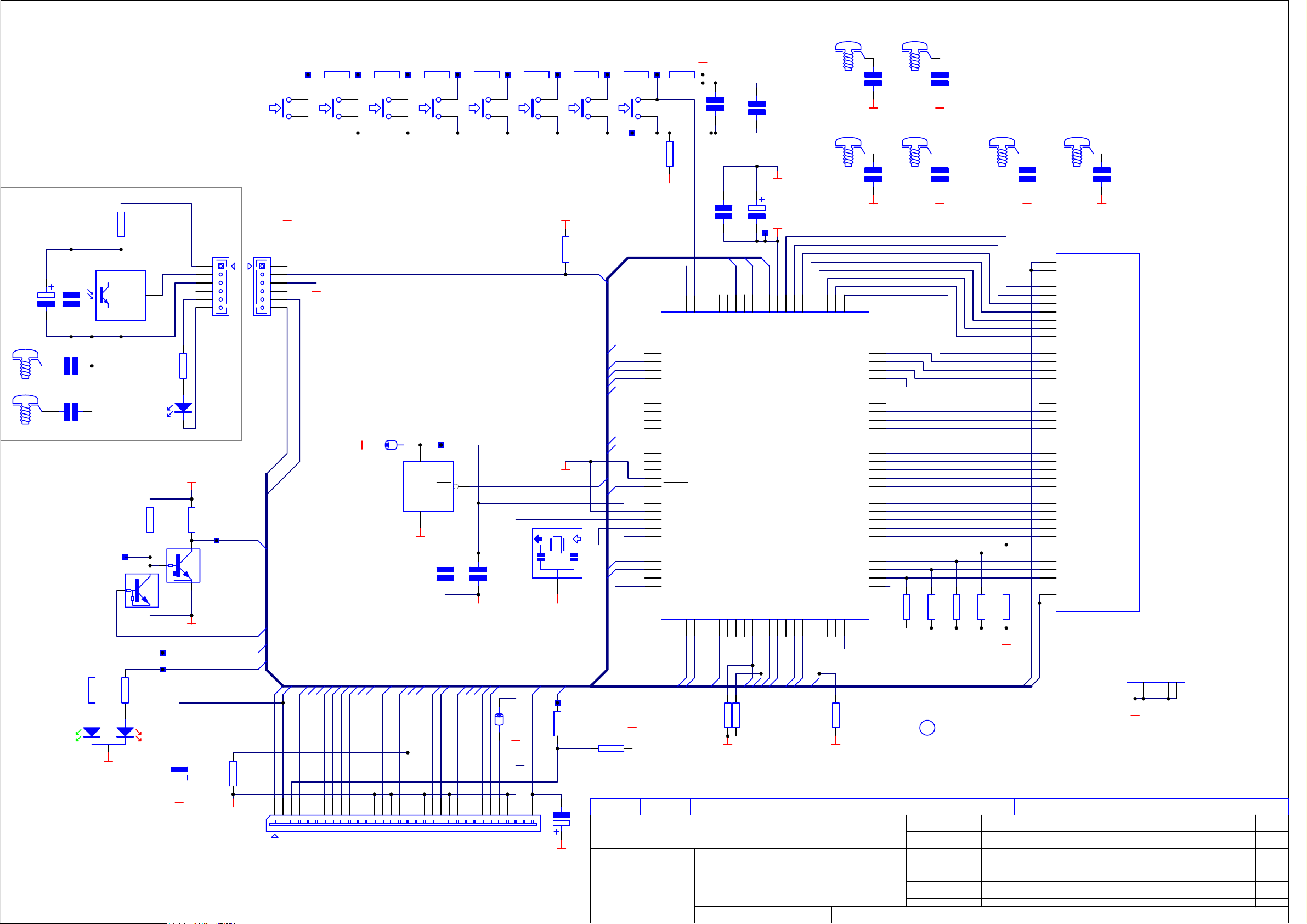
1/2X is from O/D output from CPU
R36
10R
TR1
BC856B
SOT-23
L2
10U
VC
RFAC
RFDC
TE
FE
RW
1/2X
VC
FE
TE
RFDC
RFAC
P14
R33 15K
R12 100K
R34 47K0W125 0805
R37 0R0
R38 0R0
0W125
0805
BCK
PCMD
LRCK
DRAWING TITLE
ARCAM
A & R Cambrid ge Ltd.
Pembroke Avenue
Waterbeach
Cambrid ge CB5 9QR
C3
100N 50V
SPDR
SSTP
SFDR
SRDR
TFDR
TRDR
FFDR
FRDR
P32
P33
P34
P35
P36
R44 330R
R45 330R
R46 330R
C15
3N9
50V
0805
DGND
SCLK_MECH
SDATA_MECH
LRCLK_MECH
C32
10P
100V
DGND
C25
470P
100V
CD36 - CD Interface
Filename:
Notes:
Contact Engineer:
R6 10K
R10 8K2
P1
P2
P37
C33
10P
100V
CD Interface.Sch
R25 2K7
R60 13K
R55 2K7
R56 2K7
R57 2K7
R58 2K7
R59 2K7
DGND
P4
+3V6D
DGND
18
15
20
R39
R7
R13
100K
14
17
19
GFS
XUGF16XPCK
C2PO
SCOR
WFCK
IC3
CXD3017Q
LQFP-80
TE41CE42RFDC43ADIO44AVSS045IGEN46AVDD047ASYO48ASYI49BIAS50RFAC51AVSS352CLTV53FILO54FILI55PCO56AVDD357VSS58VDD59DOUT
P39
P40
P41
C29
470N
1206
16V
+3V6D
R40 1M0
C27
100P 100V
C37
1N5
50V
CD/CDR not used on Solo
Option on CD73 N/F
05_E108 JR / MJT 14-07-05 0805 caps dropped to 50V where poss, PCB footprint changes 2.0
05_E090 JR 06-05-05 update to issue 1.0 1.0
05_E072 JR 05-04-05 Brought up to date with Solo B.0
05_E006 JR 17-01-05 First release A.0
ECO No. DE SCRIPTION OF CHANGE
C5
100N
50V
SPOA12SPOB13XLON
0805
P7
8
9
11
10
VDD
SCLK
ATSK
P42
P43
INITIALS
Printed:
Page 4

Main Board Supplies
VFD supplies
DGND
R105
100K
P102 P103
CON101
4
3
2
1
AMP
CT
SEC1A
CON103
1
20mm HLDR
2
3
4
5
6
AMP
CT
SEC1B
+5VD
TR106
BC846B
SOT-23
FHLDR100
T2A
FS100
S506
TR108
MMUN2111LT1
SOT-23
P124
Fit either SOT-23 or
DO-35 zener, 2%
DZ108
BZX84B
BZX79B
30V 2%
SOT-23
R106
NF
100K
R107
P104
10K
C105
100N
50V
C106
100N
50V
D107BAV70
SOT-23
P122 P123
C100
100N
50V
DZ105
30V
DO-35
TR103
BC846B
SOT-23
R113
270R
This is not a rectif ier
It is an AC switch
D102
2KBP02
P113
R115
1K0
C112 100U F
6.3V
SM
Standby - active LOW
~PWRDN_P
R111
47K
DZ102
BZX84C
SOT-23
R110
2K7
DZ107
BZX84C
15V
SOT-23
R127
TR111
100K
R128
100R
R112
47K
P100
5V6
TR113
ZTX753
ELINE
TR113_C
DBR100
3BDF04M
C107
100N
50V
C108
100N
50V
P132
BC846B
SOT-23
P131
TR112
BC846B
SOT-23
TR104
P114
MMUN2211LT1
C120
1uF
25V
1206
DGND
R123
470R
R124
C101
100N
50V
VFD power supply changed to cure flicker
M104
NTF3055V
SOT-223
DZ106
10V
BZX84C
SOT-23
470R
HT can be varied by changing R110
is 27.6V with 2k7
+5VD
MMUN2111LT1
P108
SOT-23
R108
10K
Transistors ON for enable
P101
R109
10K
C117
3300UF
25V
YK
AC present detect and timer
P115
SOT-23
TR105
MMUN2211LT1
SOT-23
R104
10K
P116
SOT-23
TR110
MMUN2111LT1
TR114
MMUN2211LT1
SOT-23
TR109
P109
VfilA
VfilB
C116
3300UF
25V
YK
D105
S1D
DO-214AC
DAC_RELAY
Contacts N/C
VfilA
VfilB
-30V
IC102E
10 11
74HC14
SO-14
SW50-2
8.8C/W
1uF
25V
~PWRDN_P
HS101A
C109
1206
REG101
D104 S1D
TO-220
R120
360R
DGND
LM317T
ADJ
DO-214AC
R139
0R0
XRST
R122
120R
C121
10uF
10V
1206
+12VUNREG
+5VD
Supply, mainly to CPU
on display board.
Only supply that does
not go into standby.
C122
10uF
10V
1206
DZ103
10V
SOT-23
R131
10K
BZX84C
M102 NTF2955
SOT-223
P110
R132
10K
P117
MMUN2211LT1SOT-23
DGND
10DAC supply from power board
D103
DO-214AC
DO-214AC
LM317T
C110
1uF
25V
1206
DGND
S1D
LM1086CT-ADJ
TO-220
C118
1uF
25V
1206
D106
S1D
SW50-2
TO-220
ADJ
R129
510R
REG104
ADJ
R114
1K0
R140
0R0
R141
0R0
DGND
R130
270R
C123
10uF
10V
1206
R125
220R
C115
220UF
16V
YK
C124
10uF
10V
1206
HS100A
SW50-2
+12VUNREG_SW
~PWRDN_N
TR101
The method o f system reset, po wer up/down via mains swit ch and standby mode has
changed from that of the CD73.
When the CPU is reset by the LM809, IC300 on the display board, after a short
delay, approx. 200mS, the ~STANDBY line goes HIGH.
The ~STANDBY line, in turn, generates 2 more timed signals.
1. ~XRS T, the system reset line, w hich goes HIGH 1s after the standby line goes
high, and is also gated into the 10DAC power-on mute cct.
2. ~PWRDN, which switches off all the unregulated supplies except that which drives
the +5VD to the CPU.
This delays the LV power being switched off by 1s after the output is muted.
The XRST line from the CPU is no longer used
8.8C/W
HS102A
8.8C/W
REG102
+7VD
+3V6D
CON100
AMP
CT
QTY DESCRIPTIONPART No. NOTESITEM
5
4
3
2
1
DGND
+8VDACunreg
~PWRDN_N
PWRD_N
~PWRDN_P
+18Vunreg
This becomes analogue
ground when linked
on 10DAC board
DGND
-18Vunreg
DZ104BZX84C
10V
SOT-23
R101
10K
P111
XRST
P134
P133
P130
R103
10K
10V
SOT-23
BZX84C
M103 NTF2955
SOT-223
P112
R136
10K
TR100
MMUN2211LT1SOT-23
DGND
IC102D
8 9
74HC14
SO-14
IC102F
12 13
74HC14
SO-14
M100 NTF2955
10V
M101
12
56
P128
P127
R133
360R
DGND
SOT-223
R102
10K
MMUN2211LT1SOT-23
D108 S1D
ADJ
C129
1uF
25V
1206
C130
1uF
25V
1206
Standby - active LOW
TR102
DO-214AC
C127
10uF
10V
1206
~XRST
D109
BAV99
SOT-23
P119
P120
50V
DZ100BZX84C
SOT-23
TR107
MMUN2111LT1
SOT-23
P126
R100
22K
DZ101
NTF3055V
SOT-223
HS103A
6072B
7C/W
C126
1uF
25V
1206
IC102B
3 4
74HC14
SO-14
IC102A
74HC14
SO-14
DGND
IC102C
P118
74HC14
SO-14
The drive voltage to the NPN & PNP digital
transistors is separated in order to prevent an
indeterminate bias voltage appearing on their
bases due to their internal resistors across the
supply.
P129
REG105
TO-220
LM1086CT-ADJ
R134
120R
+5VD
R142
1M0
P121
R143
1M0
+5VD
14
C125
100N
DGND
+18VU_SW
~PWRDN_N
-18VU_SW
+5VDAC_SW
C128
10uF
10V
1206
~PWRDN_N
R135
100K
R137 1K 0
REMOVE THIS
RESISTOR TO DISABLE
STANDBY MODE
IC102G
VCC
7
GND
74HC14
SO-14
~STANDBY
C
Copyright 2005 A&R Cambridge Ltd
ITEM100 3 Sil Pad For TO-220 HS InsulatorF082
ITEM103 1 M Screw Torx M3x10MM ST ZPHA3V10A
ITEM104 1 M3 Hex Nut NylocHJ3A00F
ITEM101 3 Clip For SW Profile HeatsinkF006
ITEM102 1 Fuseholder Cover For 20mm FuseholderF022
DRAWING TITLE
ARCAM
A & R Cambrid ge Ltd.
Pembroke Avenue
Waterbeach
Cambrid ge CB5 9QR
CD36 Main Board PSU Section
Filename:
Notes:
Contact Engineer: 14-Jul-2005
PSUsection.Sch
L981AY
05_E108 JR / MJT 14-07-05 0805 caps dropped to 50V where poss, PCB footprint changes 2.0
05_E090 JR 06-05-05 update to issue 1.0 1.0
05_E072 JR 05-04-05 Changes, mainly to VFD supply B.0
05_E006 JR 17-01-05 First release A.0
Contact Tel: 01223 203251 (or 203200)John Roscoe
ECO No. DE SCRIPTION OF CHANGE
INITIALS
Printed:
DATE
45Sheet of
A2
DRAWING NO.
L985CT
ISSUE
Page 5

Remote IR in
SKT200
KUNMING
HTJ
NC
EMC_GND
Trigger Input
SKT202
L200 600R@100MHz
L201
600R@100MHz
C200
100P
100V
NCL
C201
100P
100V
RMLED+
RMLED-
RMLED+
RMLED-
IC200A
74HCT125D
SPDIF
5 6
P201
DGND
R200 100R
2 3
SO-14
1
DGND DGND
P200
R201 100R
9 8
12 11
DGND
IC200B
74HCT125D
SO-14
4
IC200C
74HCT125D
SO-14
10
IC200D
74HCT125D
SO-14
13
SPDIF COAX OUTPUT
R203 1K0
P207
R204 1K0
P208
R205 1K0
P209
P202
DGND
+5VD
1
I/P
R206
3K3
2
VCC
GND
3
+5VD
DGND
R202
100R
R208
10R
TX201
JFJ1001-010010
D200
BAT54S
SOT-23
L202
120R@100MHz
P203 P204 P205
C203
47P
100V
C204
100N 50V
C205
100N
50V
TX200
PCB Mount SMT
7A29398
C206
100UF
10V
YXF
SKT201
KUNMING
GOLD
SCRN
EMC_GND
C202
100P
100V
NF
SPDIF_OP
SPDIF_GND
C207
10N
50V
0805
51
3
4
L203
1000R @ 100MHz
1
2
P206
84
DLW31S
KUNMING
HTJ
DGND
L
R
3
1
DGND
TRIGSW
NCR
TRIGIN
10K pull-up on VFD board
TRIGSW
IC200E
74HCT125D
SO-14
VCC
GND
+5VD
14
C208
10uF
DGND
10V
1206
7
TRIGIN
2
OPTICAL OUT
DRAWING TITLE
ARCAM
A & R Cambridge Ltd.
Pembroke Avenue
Waterbeach
Cambridge CB5 9QR
CD36 Main Board RC5 & digital out
Filename:
Notes:
Contact Engineer : 14-Jul-2005
RC5 in & Digital out.Sch
Contact Tel: 01223 203251 (or 203200)John Roscoe
05_E108 JR / MJT 14-07-05 0805 caps dropped to 50V where poss, PCB footprint changes 2.0
05_E090 JR 06-05-05 update to issue 1.0 1.0
05_E072 JR 05-04-05 Jack type corrected B.0
05_E006 JR 17-01-05 First release A.0
ECO No. DESCRIPTION OF CHANGE
INITIALS
Printed:
DATE
C
Copyright 2005 A&R Cambridge Ltd
55Sheet of
A3
DRAWING NO.
L985CT
ISSUE
 Loading...