

Page 1

AV950/AVR750/450/380
HANDBOOK AVR surround amplifiers
MANUEL Amplificateur surround AVR
HANDBUCH AVR Surround Verstärker
HANDLEIDING AVR surroundversterker
MANUAL AVR amplificadores surround
РУКОВОДСТВО AVR объемного усилители
MANUALE Amplificatori Surround AVR
手册AVR环绕声放大器
AVR750
Page 2

Page 3

AV950/AVR750/450/380
HANDBOOK AVR surround amplifiers
English
AVR750
Page 4

English
safety
Important safety instructions
1. Read these instructions.
2. Keep these instructions.
3. Heed all warnings.
4. Follow all instructions.
5. Do not use this apparatus near water.
6. Clean only with a dry cloth.
Unplug the unit from the mains supply before cleaning.
e case should normally only require a wipe with a so,
lint-free cloth. Do not use chemical solvents for cleaning.
We do not advise the use of furniture cleaning sprays or
polishes as they can cause permanent white marks.
7. Do not block any of the ventilation openings.
Install in accordance with the manufacturer’s
instructions.
8. Do not install near any heat sources such as
radiators, heat registers, stoves, or other apparatus
(including ampliers) that produce heat.
9. Do not defeat the safety purpose of the polarized or
grounding type plug.
A polarized plug has two blades with one wider than the
other. A grounding type plug has two blades and a third
grounding prong. e wide blade or the third prong
is provided for your safety. When the provided plug
does not t into your outlet, consult an electrician for
replacement of the obsolete outlet.
10. Protect the power cord from being walked on or
pinched particularly at plugs, convenient receptacles,
and the point where they exit from the apparatus.
CAUTION: To reduce the risk of electric shock, do not remove cover (or back). No user serviceable parts inside. Refer servicing to qualified
service personnel.
WARNING: To reduce the risk of fire or electric shock, do not expose this apparatus to rain or moisture.
The lightning flash with an arrowhead symbol, within an equilateral triangle, is intended to alert the user to the presence of
uninsulated ‘dangerous voltage’ within the product’s enclosure that may be of sufficient magnitude to constitute a risk of electric
shock to persons.
The exclamation point within an equilateral triangle is intended to alert the user to the presence of important operating and
maintenance (servicing) instructions in the literature accompanying the appliance.
CAUTION: In Canada and the USA, to prevent electric shock, match the wide blade of the plug to the wide slot in the socket
and insert the plug fully into the socket.
11. Only use the attachments/accessories specied by
the manufacturer.
12. Use only with a cart, stand, tripod, bracket, or
table specied by the manufacturer,
or sold with the apparatus.
When a cart is used, use caution
when moving the cart/apparatus
combination to avoid injury from
tip-over.
13. Unplug this apparatus during lightning storms or
when unused for long periods of time.
14. Refer all servicing to qualied service personnel.
Servicing is required when the apparatus has been
damaged in any way, such as power supply cord or plug
is damaged, liquid has been spilled or objects have fallen
into the apparatus, the apparatus has been exposed to
rain or moisture, does not operate normally, or has been
dropped.
15. Object or liquid entry
WARNING – Take care that objects do not fall and
liquids are not spilled into the enclosure through any
openings. e equipment shall not be exposed to
dripping or splashing. Liquid-lled objects such as vases
should not be placed on the equipment.
16. Service Instructions
CAUTION – ese servicing instructions are for use by
qualied service personnel only. To reduce the risk of
electric shock, do not perform any servicing other than
that contained in the operating instructions unless you
are qualied to do so.
17. Climate
e equipment has been designed for use in moderate
climates and in domestic situations. Unplug this
equipment during lightning storms to prevent possible
damage from a strike or mains surge.
18. Power sources
Only connect the equipment to a power supply of
the type described in the operating instructions or as
marked on the equipment.
e primary method of isolating the equipment from
the mains supply is to remove the mains plug. e
equipment must be installed in a manner that makes
disconnection possible.
19. Power-cord protection
Power supply cords should be routed so that they are not
likely to be walked on or pinched by items placed upon
or against them. Pay particular attention to the point
where they exit from the equipment.
20. Power lines
Locate any outdoor antenna/aerial away from power
lines.
21. Speaker connections
Any speakers must be connected to the AV950/
AVR750/450/380 using class II wire (i.e. no connection
to Earth should be made). Failure to observe this
precaution may cause the unit to become damaged.
22. Non-use periods
Class II product
is equipment is a Class II or double
insulated electrical appliance. It has been
designed in such a way that it does not
require a safety connection to electrical
earth (‘ground’ in the U.S.).
If the equipment is not being used for an extended
period, we recommend that you unplug the power cord
of the equipment from the outlet, to save power.
23. Abnormal smell
If an abnormal smell or smoke is detected from the
equipment, turn the power o immediately and unplug
the equipment from the wall outlet. Contact your dealer
and do not reconnect the equipment.
CAUTIONS ON INSTALLATION
For proper heat dispersal, do not install this unit
in a conned space, such as a bookcase or similar
enclosure.
• More than 0.3 m (12 in.) is recommended.
• Do not place any other equipment on this unit.
z
zz
z
Wall
FCC INFORMATION FOR US CUSTOMERS
1. PRODUCT
is product complies with Part 15 of the FCC Rules.
Operation is subject to the following two conditions:
(1) is device may not cause harmful interference,
and (2) this device must accept any interference
received, including interference that may cause
undesired operation.
2. IMPORTANT NOTICE:
DO NOT MODIFY THIS PRODUCT
is product, when installed as indicated in the
instructions contained in this manual, meets FCC
requirements. Modication not expressly approved
by ARCAM may void your authority, granted by the
FCC, to use the product.
3. NOTE
is product has been tested and found to comply
with the limits for a Class B digital device, persuant
to Part 15 of the FCC Rules. ese limits are designed
to provide reasonable protection against harmful
interference in a residential installation.
SAFETY INFORMATION
FOR EUROPEAN CUSTOMERS
• Avoidhightemperatures.Allowforsucient
heat dispersion when installed in a rack.
• Handlethepowercordcarefully.Holdtheplug
when unplugging the cord.
• Keeptheunitfreefrommoisture,water,and
dust.
• Unplugthepowercordwhennotusingtheunit
for long periods of time.
• Donotobstructtheventilationholes.
• Donotletforeignobjectsintotheunit.
• Donotletinsecticides,benzene,andthinner
come in contact with the unit.
• Neverdisassembleormodifytheunitinanyway.
• Ventilationshouldnotbeimpededbycovering
the ventilation openings with items, such as
newspapers, tablecloths or curtains.
is product generates, uses and can radiate radio
frequency energy and, if not installed and used in
accordance with the instructions, may cause harmful
interference to radio communications. However,
there is no guarantee that interference will not occur
in a particular installation. If this product does cause
harmful interference to radio or television reception,
which can be determined by turning the product
OFF and ON, the user is encouraged to try to correct
the interference by one or more of the following
measures:
• Reorientorrelocatethereceivingantenna.
• Increasetheseparationbetweentheequipment
and receiver.
• Connecttheproductintoanoutletonacircuit
dierent from that to which the receiver is
connected.
• Consultthelocalretailerauthorizedtodistribute
this type of product or an experienced radio/TV
technician for help.
• Nakedamesourcessuchaslightedcandles
should not be placed on the unit.
• Observeandfollowlocalregulationsregarding
battery disposal.
• Donotexposetheunittodrippingorsplashing
uids.
• Donotplaceobjectslledwithliquids,suchas
vases, on the unit.
• Donothandlethemainscordwithwethands.
• WhentheswitchisintheOFFposition,the
equipment is not completely switched o from
MAINS.
• eequipmentshallbeinstallednearthe
power supply so that the power supply is easily
accessible.
A NOTE ABOUT RECYCLING:
is product’s packaging materials are recyclable and can be reused. Please dispose of any materials in accordance
with the local recycling regulations.When discarding the unit, comply with local rules or regulations.
Batteries should never be thrown away or incinerated but disposed of in accordance with the local regulations
concerning battery disposal.
is product and the supplied accessories, excluding the batteries, constitute the applicable product according to
the WEEE directive.
CORRECT DISPOSAL OF THIS PRODUCT
ese markings indicate that this product should not be
disposed with other household waste throughout the EU.
To prevent possible harm to the environment or human
health from uncontrolled waste disposal and to conserve
material resources, this product should be recycled
responsibly.
To dispose of your product, please use your local return and collection systems or contact the retailer where the
product was purchased.
E-3E-2
Page 5

English
Contents
safety ...........................................................E-2
welcome ......................................................E-5
before you begin… ..................................E-6
rear panel connectors ..............................E-9
audio/video connections ..................... E-10
Connection guide ................................................ E-12
radio connectors .................................... E-13
other connectors .................................... E-14
speakers ................................................... E-15
operation ................................................. E-17
front panel operation ............................ E-19
remote control ........................................ E-20
essential setup ........................................ E-26
auto speaker setup ................................ E-27
setup menus ........................................... E-28
decoding modes .................................... E-33
Dolby volume ........................................................ E-35
tuner operation ...................................... E-36
network/usb operation ........................ E-37
multi-room set up .................................. E-38
Multi-room connection guide ........................ E-39
customising the CR450 ......................... E-40
trouble shooting ..................................... E-42
specifications .......................................... E-44
product guarantee ................................ E-48
ank you and congratulations on purchasing your Arcam FMJ Receiver.
Arcam has been producing specialist audio products of remarkable quality for over three
decades and the new AV950/AVR750/450/380 Receivers are the latest in a long line of award
winning Hi-Fi. e design of the FMJ range draws upon all of Arcam’s experience as one of the
UK’s most respected audio companies, to produce Arcam’s best performing range of products yet
– designed and built to give you years of viewing and listening enjoyment.
is handbook is intended to give you a detailed guide to using the AV950/AVR750/450/380
Receiver. It starts by giving advice on installation, moves on to describe how to use the product
and nishes with additional information on the more advanced features. Use the contents list
shown on this page to guide you to the section of interest.
We hope that your FMJ receiver will give you years of trouble-free operation. In the unlikely
event of any fault, or if you simply require further information about Arcam products, our
network of dealers will be happy to help you. Further information can also be found on the
Arcam website at www.arcam.co.uk.
e FMJ development team
welcome
E-4
Professional Installation?
It may be that the AV950/AVR750/450/380 has been installed and set up as part of your Hi-Fi installation by a
qualied Arcam dealer. In this case, you may wish to skip the sections of this handbook dealing with installation
and setting up, and move directly to the sections dealing with using the unit. Use the Contents list to guide you to
these sections.
DIY setup?
e AV950/AVR750/450/380 is a powerful and sophisticated piece of AV equipment. If you are setting the unit
up yourself, it is recommended that you read this handbook thoroughly before beginning. For instance, correct
speaker conguration and placement is a key to getting the most out of your AV950/AVR750/450/380 and
making sure that all the elements of your system work in harmony.
E-5
Page 6

English
before you
begin…
e AV950, AVR380, AVR450 and AVR750 are
high-quality and high-performance home-cinema
processors and ampliers built to Arcam’s quality
design and manufacturing standards. ey combine
digital processing with high-performance audio and
video components to bring you an unrivalled homeentertainment centre.
e AV950/AVR750/450/380 allows switching and
control of seven analogue and six digital audio sources
in addition to internal FM (and, in the case of the
AVR450, AVR750 and AV950, DAB) radio – as well as
networked and USB audio sources – making any of the
models an ideal hub for both home-cinema and twochannel stereo systems.
Since many of these source components are also capable
of generating video signals, the AV950/AVR750/450/380
AVR750
includes broadcast-quality switching for HDMI,
Composite and Component video signals. Control of the
AV950/AVR750/450/380 is either by front panel control
buttons, IR remote control or RS232 port.
e CR450 remote control supplied with the AV950/
AVR750/450/380 is a twelve-device ‘universal’ learning
remote control which is simple to use, and once set up is
able to control a complete system. It can be programmed
using its vast internal code library to control CD and BD
players, PVRs, TVs and other devices.
e installation of the AV950/AVR750/450/380 in a
listening room is an important process which requires
care at every stage. For this reason, the installation
information is very comprehensive and should be
followed carefully to achieve an unrivalled level of
performance.
e AV950/AVR750/450/380 receivers are designed
to produce a level of performance that will truly bring
music and movies to life.
Placing the unit
< Place the unit on a level, rm surface, avoiding
direct sunlight and sources of heat or damp.
< Do not place the AV950/AVR750/450/380 on top of
a power amplier or other source of heat.
< Do not place the amplier in an enclosed space
such as a bookcase or closed cabinet unless there
is good provision for ventilation. e AV950/
AVR750/450/380 will run warm during normal
operation.
< Do not place any other component or item on top of
theamplierasthismayobstructairowaroundthe
heat-sink, causing the amplier to run hot. (e unit
placed on top of the amplier would become hot,
too.)
< Make sure the remote-control receiver on the front
panel display is unobstructed, otherwise this will
impair the use of the remote-control. If line-of-sight
is impractical, a remote-control repeater can be used
with the rear panel connector (see page E-14).
< Do not place your record deck on top of this
unit. Record decks are very sensitive to the noise
generated by mains power supplies which will be
heard as a background ‘hum’ if the record deck is too
close.
Power
e amplier is supplied with a moulded mains plug
already tted to the lead. Check that the plug supplied
ts your supply – should you require a new mains lead,
please contact your Arcam dealer.
If your mains supply voltage or mains plug is dierent,
please contact your Arcam dealer immediately.
e AV950/AVR750/450 can be switched for operation
between 220–240V (switch position 230V) and
110–120V (switch position 115V).
NOTE
Ensure that the AV950/AVR750/450 is switched o
and the power lead removed before changing the
position of the voltage range switch.
Push the IEC plug end of the power cable into the
socket on the back of the amplier, making sure that it
is pushed in rmly. Plug the other end of the cable into
your mains socket and, if necessary, switch the socket
on.
e AV950/AVR750/450/380 can be turned on using the
POWER switch on the front panel. While switched on, the
front panel LED will glow green.
Standby power
e AV950/AVR750/450/380 can be switched into
standby mode using the P button on the CR450
remote control. While in standby mode the front panel
LED will glow red and power consumption is less than
0.5 Watts.
While in Standby mode, it may be possible to hear a
slight residual hum coming from the mains transformer
inside the amplier. is is perfectly normal. However,
if the unit is to be le unused for an extended period,
we recommend that you disconnect it from the mains
supply to save power.
Interconnect cables
We recommend the use of high-quality screened cables
that are designed for the particular application. Other
cables will have dierent impedance characteristics
that will degrade the performance of your system (for
example, do not use cabling intended for video use to
carry audio signals). All cables should be kept as short
as is practically possible.
It is good practice when connecting your equipment to
make sure that the mains power-supply cabling is kept
as far away as possible from your audio cables. Failure to
do so may result in unwanted noise in the audio signals.
For information on speaker cabling, please refer to the
‘Speakers’ section, beginning on page E-15.
Radio interference
e AV950/AVR750/450/380 is an audio device
containing microprocessors and other digital
electronics. Each model has been designed to very high
standards of electromagnetic compatibility.
is is a Class A product. In a domestic environment
this product may cause radio interference, in which case
the user may be required to take adequate measures.
If the AV950/AVR750/450/380 causes interference to
radio or television reception (which can be determined
by switching the AV950/AVR750/450/380 o and on),
the following measures should be taken:
< Re-orient the receiving antenna or route the antenna
cable of the aected receiver as far as possible from
AV950/AVR750/450/380 and its cabling.
< Relocate the receiver with respect to the AV950/
AVR750/450/380.
< Connect the aected device and the AV950/
AVR750/450/380 to dierent mains outlets.
If the problem persists, please contact your Arcam
dealer.
E-7E-6
Page 7

English
Trademark acknowledgements
~ 50 – 60 Hz
100W MAX
1.2A MAX TRIG Z2 Z2 IR
TRIG Z1
RS232
DC6V
Z1 IR
OUTPUT1 OUTPUT2AV
AV
ETHERNET
USB 5V / 1A
115 230
FM/DAB
PVR
PVR
VCRBDSAT
AV BD
Y
Pb
Pr
SAT
STBZ2 OUT
Z2
VIDEO OUT
GAME PVR
STB BD
PVRS AT
BDAV
BDCDCD
GAME
STB
STB
GAME
OPTICAL
COAXIAL
ARC
COMPOSITE
DIGITAL AUDIO
ANALOGUE AUDIO
HDMI
COMPONENT
Arcam is a registered trademark of A & R Cambridge Ltd.
Dolby Volume
Manufactured under license from Dolby
Laboratories. Dolby and the double-D symbol
are trademarks of Dolby Laboratories.
Dolby TrueHD, Digital, Digital Plus,
PL IIx
Manufactured under license from Dolby
Laboratories. Dolby, Pro Logic, and the
double-D symbol are trademarks of Dolby
Laboratories.
DTS-HD Master Audio™
Manufactured under license under U.S. Patent
Nos: 5,956,674; 5,974,380; 6,226,616; 6,487,535;
7,212,872; 7,333,929; 7,392,195; 7,272,567 &
other U.S. and worldwide patents issued &
pending.
DTS-HD, the Symbol, & DTS-HD and the
Symbol together are registered trademarks &
DTS-HD Master Audio is a trademark of DTS,
Inc. Product includes software.
© DTS, Inc. All Rights Reserved.
DTS-HD High Resolution Audio™
Manufactured under license under U.S. Patent
Nos: 5,956,674; 5,974,380; 6,226,616; 6,487,535;
7,212,872; 7,333,929 & other U.S. and worldwide
patents issued & pending.
DTS-HD, the Symbol, & DTS-HD and the
Symbol together are registered trademarks, &
DTS-HD High Resolution Audio is a trademark
of DTS, Inc. Product includes software.
© DTS, Inc. All Rights Reserved.
DTS Digital Surround
ES|Neo:6|96/24™
Manufactured under license under U.S. Patent
Nos: 5,956,674; 5,974,380; 6,226,616; 6,487,535;
7,003,467; 7,212,872 & other U.S. and worldwide
patents issued & pending.
DTS, the Symbol, & DTS and the Symbol
together are registered trademarks & DTS
Digital Surround | ES | Neo:6 | 96/24 is a
trademark of DTS, Inc. Product includes
software.
© DTS, Inc. All Rights Reserved.
NOTE
Please read the ‘Placing the unit’, ‘Power’ and
‘Interconnect cables’ sections on see page E-7 before
AAC/AAC Plus
aacPlus is a trademark of Coding Technologies.
See www.codingtechnologies.com for more
information.
FLAC
vTuner
FLAC Decoder Copyright © 2000, 2001, 2002,
2003, 2004, 2005, 2006, 2007, 2008 Josh Coalson
Redistribution and use in source and binary
forms, with or without modification, are
permitted provided that the following conditions
are met:
- Redistributions of source code must retain the
above copyright notice, this list of conditions
and the following disclaimer.
- Redistributions in binary form must
reproduce the above copyright notice, this list of
conditions and the following disclaimer in the
documentation and/or other materials provided
with the distribution.
- Neither the name of the Xiph.org Foundation
nor the names of its contributors may be used
to endorse or promote products derived from
this software without specific prior written
permission.
THIS SOFTWARE IS PROVIDED BY
THE COPYRIGHT HOLDERS AND
CONTRIBUTORS ‘AS IS’ AND ANY EXPRESS
OR IMPLIED WARRANTIES, INCLUDING,
BUT NOT LIMITED TO, THE IMPLIED
WARRANTIES OF MERCHANTABILITY AND
FITNESS FOR A PARTICULAR PURPOSE
ARE DISCLAIMED. IN NO EVENT SHALL
THE FOUNDATION OR CONTRIBUTORS
BE LIABLE FOR ANY DIRECT, INDIRECT,
INCIDENTAL, SPECIAL, EXEMPLARY, OR
CONSEQUENTIAL DAMAGES (INCLUDING,
BUT NOT LIMITED TO, PROCUREMENT OF
SUBSTITUTE GOODS OR SERVICES; LOSS
OF USE, DATA, OR PROFITS; OR BUSINESS
INTERRUPTION) HOWEVER CAUSED AND
ON ANY THEORY OF LIABILITY, WHETHER
IN CONTRACT, STRICT LIABILITY, OR
TORT (INCLUDING NEGLIGENCE OR
OTHERWISE) ARISING IN ANY WAY OUT
OF THE USE OF THIS SOFTWARE, EVEN IF
ADVISED OF THE POSSIBILITY OF SUCH
DAMAGE.
This product is protected by certain intellectual
property rights of NEMS and BridgeCo. Use
or distribution of such technology outside of
this product is prohibited without a license
from NEMS and BridgeCo or an authorized
subsidiary.
MP3
iPod
MPEG Layer-3 audio decoding technology
licensed from Fraunhofer IIS and Thomson
multimedia
iPod is a trademark of Apple Inc., registered in
the US and other countries.
HDMI, the HDMI logo and High-Definition
Multimedia Interface are trademarks or
registered trademarks of HDMI Licensing LLC.
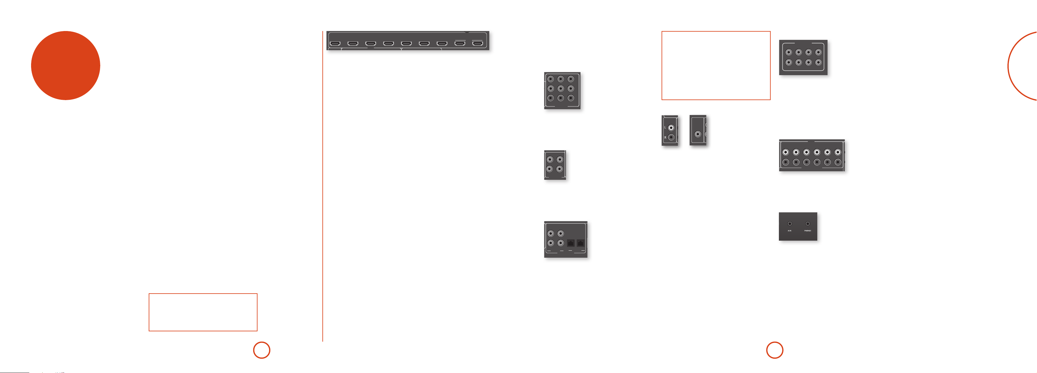
rear panel
connectors
AVR750
AVR450
AVR380
Audio connectors
Analogue two-channel,
see page E-11.
Preamplifier output
see page E-11.
AV950
Preamplifier output
see page E-11.
HDMI connectors
For information, see page E-10.
STB
GAME
STBZ2 OUT
PREAMP OUT
PREAMP OUT
SUB
SR SL
SBR
FLFR
C
SBL
HDMI
GAME
ANALOGUE AUDIO
CFL SL SBL
SBRSUBSRFR
ZONE 2 R ZONE 2 L
SBR SR FR C
Digital connectors
Coaxial and optical digital audio
connectors, see page E-11.
PVR
VCRBDSAT
BDAV
PVR
ZONE 2 R
SBR SR FR C FL SL SBL
CLASS 2 WIRING
SBR
ZONE 2 R ZONE 2 L
PVRSAT
ETHERNET
BDCDCD
COAXIAL
DIGITAL AUDIO
SR FR C FL SL SBL
AV
STB
OPTICAL
SPEAKER OUTPUTS
8Ω LOAD IMPEDANCE RECOMMENDED
Speaker connectors
For information, see page E-16.
BALANCED OUTPUTS
SUB
FL SL SBL
OUTPUT1 OUTPUT2AV
USB 5V / 1A
AVR750
AVR450
AV950
Composite video coaxial and
Component video (Y, Pb, Pr)
connectors, see page E-11.
Zone2 connection, see page E-38.
FM/DAB
Video connectors
FM aerial socket, or DAB
aerial socket (AV950,
AVR450, AVR750 only).
ARC
Y
Pb
Pr
SAT
RS232
DC6V
1.2A MAX TRIG Z2 Z2 IR
ZONE 2 L
FM/DAB
Z2
VIDEO OUT
GAME PVR
STB BD
COMPOSITE
AV BD
COMPONENT
~ 50 – 60 Hz
1.5KW MAX
115 230
Power inlet
Connect the correct mains cable here
Voltage select
Ensure the voltage selected
matches your local power supply.
e AVR380 does not require a
AVR380
voltage select switch: the voltage
is set according to local market
requirements.
connecting up your AV950/AVR750/450/380!
TRIG Z1
Z1 IR
Aerials, control and communication
Network, USB, FM/DAB aerial, voltage
output, serial control, trigger and IR
connectors, see page E-13, E-14.
E-9E-8
Page 8
English
Y
1.2A MAX TRIG Z2 Z2 IR
TRIG Z1
RS232
DC6V
Z1 IR
1.2A MAX TRIG Z2 Z2 IR
TRIG Z1
RS232
DC6V
Z1 IR
AV BD
Y
Pb
Pr
SAT
COMPONENT
1.2A MAX TRIG Z2 Z2 IR
TRIG Z1
RS232
DC6V
Z1 IR
OUTPUT1 OUTPUT2AV
ETHERNET
USB 5V / 1A
FM/DAB
PVR
VCRBDSAT
AV BD
Y
Pb
Pr
SAT
Z2
VIDEO OUT
GAME PVR
STB BD
ARC
COMPOSITE
COMPONENT
1.2A MAX TRIG Z2 Z2 IR
TRIG Z1
RS232
DC6V
Z1 IR
OUTPUT1 OUTPUT2AV
AV
ETHERNET
USB 5V / 1A
FM/DAB
PVR
PVR
VCRBDSAT
AV BD
Y
Pb
Pr
SAT
STB
Z2
VIDEO OUT
GAME PVR
STB BD
PVRSAT
BDAV
BDCDCD
GAME
STB
STB
GAME
OPTICAL
ARC
ANALOGUE AUDIO
HDMI
1.2A MAX TRIG Z2 Z2 IR
TRIG Z1
RS232
DC6V
Z1 IR
AV BD
Y
Pb
Pr
SAT
GAME PVR
STB BD
COMPOSITE
COMPONENT
~ 50 – 60 Hz
1.5KW MAX
1.2A MAX TRIG Z2 Z2 IR
TRIG Z1
RS232
DC6V
Z1 IR
OUTPUT1 OUTPUT2AV
AV
ETHERNET
USB 5V / 1A
115 230
FM/DAB
PVR
PVR
VCRBDSAT
AV BD
Y
Pb
Pr
SAT
SBR SR FR C FL SL SBL
SBR
ZONE 2 R ZONE 2 L
SR FR C FL SL SBL
STBZ2 OUT
Z2
VIDEO OUT
GAME PVR
STB BD
ZONE 2 R
CLASS 2 WIRING
ZONE 2 L
8Ω LOAD IMPEDANCE RECOMMENDED
PVRSAT
BDAV
BDCDCD
GAME
STB
STB
GAME
SPEAKER OUTPUTS
OPTICAL
COAXIAL
ARC
COMPOSITE
DIGITAL AUDIO
ANALOGUE AUDIO
HDMI
COMPONENT
1.2A MAX TRIG Z2 Z2 IR
TRIG Z1
RS232
DC6V
Z1 IR
OUTPUT1 OUTPUT2AV
AV
ETHERNET
USB 5V / 1A
FM/DAB
PVR
VCRBDSAT
AV BD
Y
Pb
Pr
SAT
Z2
VIDEO OUT
GAME PVR
STB BD
PVRSAT
BDCDCD
STB
GAME
OPTICAL
COAXIAL
ARC
audio/video
connections
Before connecting your AV950/AVR750/450/380 to
your source components and speakers, please read
through the next few pages which will explain all the
input and output connectivity that is available. e
‘Speakers’ section explains how to connect up your
speakers to avoid damage to the amplier and how to
arrange your speakers for best performance.
General
e inputs are named to make it easier to reference
connected devices (e.g. ‘BD’ or ‘VCR’). ey all have the
same input circuit, so there is no reason why you should
not connect a dierent device to any of the inputs. For
example, if you had two BD players and the AV input
was not being used, then the second BD player could be
connected to the AV input.
When connecting a video source, its audio must be
connected to the corresponding sockets. For example,
if you a had a satellite decoder plugged into a S AT video
input, the audio must be connected to the S AT audio
inputs!
Generally, HDMI connections provide better quality
than Composite, although for a video source to
be available in Zone2 you must have a Composite
connection between AV950/AVR750/450/380 and the
source.
Making connections
< Wherever possible, connect both the analogue
and digital outputs of digital sources. is enables
use of a digital input for the main zone and the
corresponding analogue input for the Zone2 output.
< Take care to place cables as far from any power
supply cabling as is practicable, to reduce hum and
other noise problems.
NOTE:
For each input, you must set the ‘Video Source’ and
‘Audio Source’ settings according to the connection
type.
(see “Input Cong.” on page E-29)
STB
GAME
HDMI
VCRBDSAT
HDMI connectors
STB, GAME, AV, SAT, BD, VCR, PVR
Connect the HDMI video outputs of your source
equipment to these corresponding HDMI inputs.
OUTPUT
Connect this output to the HDMI video input of your
display device. is output is compatible with the
HDMI 1.4 Audio Return Channel (ARC). If you have
a supported television then sound from the television’s
internal tuner (e.g. Freeview, Freesat, DVB-T) will be
available using the AV950/AVR750/450/380’s ‘Display’
input.
OUTPUT1 OUTPUT2AV
PVR
ARC
Component video connectors
ese inputs are suitable for connection to source
devices which output Component (YUV or YPbPr) high
quality analogue video signals. ese signals are usually
available from BD players, set-top boxes or games
consoles.
Y
Pb
Pr
SAT
AV BD
COMPONENT
COMPONENT VIDEO IN AV, SAT, BD
Important notes about Component video
inputs
< When you connect your devices to these
connectors, take care to follow the letter/colour
coding for each input. No damage will occur but
incorrectly coloured or unstable pictures will
result.
< eComponentvideoinputshavesucient
bandwidth for NTSC (525/60) or PAL (625/50)
video and HDTV video signals.
Zone 2 connectors
Z2 OUT
Z2
VIDEO OUT
Analogue preamplifier outputs
PREAMP OUT
CFL SL SBL
SBRSUBSRFR
All preamplier analogue outputs are buered, have a
low output impedance, are at line level and follow the
Zone1 volume control setting. ey are able to drive
long cables or several inputs in parallel if required.
For more information on connecting speakers or
additional power ampliers, see page E-15 and E-16.
Front panel PHONES socket
is socket accepts headphones with an impedance
rating between 32Ω and 600Ω, tted with a 3.5mm
stereo jack plug. e headphone socket is always active,
except when AV950/AVR750/450/380 is muted.
When the headphone jack is inserted, the speaker
outputs and analogue preamplier outputs are
automatically muted.
Connect the Component video outputs of your source
equipment to these inputs.
Composite connectors
GAME PVR
STB BD
COMPOSITE
GAME, PVR, STB, BD
Connect these inputs to the Composite outputs of your
available source equipment.
e Z2 out analogue audio connector can be used
to connect the stereo audio output of the AV950/
AVR750/450/380 to an amplier located in a second
room.
Connect the analogue video output to your Zone2
display equipment. See “multi-room set up” on page
E-38 for information.
Analogue audio inputs
GAME
HDMI
BDAV
ANALOGUE AUDIO
PVR
STB
STB, GAME, AV, BD, PVR, CD
Connect the le and right inputs to the le and right
outputs of your source equipment.
Front panel AUX input
Digital audio connectors
PVRSAT
BD
COAXIAL
CD
DIGITAL AUDIO
AV
STB
OPTICAL
SAT, PVR, BD, CD, STB, AV
Connect these inputs to the digital outputs of your
available source equipment.
e front panel AUX input can be used as an analogue or
optical digital input.
For analogue sources, use a stereo 3.5mm lead; for
digital sources use a 3.5mm optical lead. e front input
is also used for the auto-setup microphone input.
E-11E-10
Page 9

English
Connection guide
1.2A MAX TRIG Z2 Z2 IR
TRIG Z1
RS232
DC6V
Z1 IR
AV BD
Y
Pb
Pr
SAT
Z2
VIDEO OUT
GAME PVR
STB BD
ARC
COMPOSITE
COMPONENT
DAB/FM
(DAB is not available on AVR380)
Blu-ray Disc (BD) / DVD player
e diagram shows how to make audio and video
connections from a typical BD/DVD player.
e preferred video hook-up, in order of preference is:
use the HDMI connector (if HDMI output is
<
provided by the player), otherwise connect the three
Component video connectors.
use the Composite connection if HDMI or
<
Component connectors are not provided by your
player.
In each case, connect the video inputs labelled BD on the
AVR750/450/380.
e preferred audio hook-up is using the coaxial digital
connector (usually marked DIGITAL AUDIO OUT), in
addition to the coaxial analogue outputs for le and
right channels.
In each case, use the audio inputs labelled BD on the
AV950/AVR750/450/380.
Satellite receiver
A satellite receiver is connected in the same way as a BD
player, with the same order of preference according to
the outputs provided by the satellite receiver.
In each case, use the inputs labelled SAT on the AV950/
AVR750/450/380. Note that digital audio input from a
satellitereceiversometimesrequiresacoaxial/TOSLINK
(digital connector) interconnect cable, as some satellite
receivers do not implement audio over HDMI properly
or at all.
CD player
Connect the digital audio output (if provided by the
CD player) to the digital CD input of the AV950/
AVR750/450/380, using a high quality coaxial
interconnect cable.
Connect the right and le analogue audio outputs of
the CD player to the analogue CD inputs of the AV950/
AVR750/450/380, using a pair of high quality coaxial
interconnect cables.
radio
FM/DAB
USB 5V / 1A
connectors
STB
GAME
STBZ2 OUT
PREAMP OUT
GAME
CFL SL SBL
HDMI
BDAV
ANALOGUE AUDIO
SBRSUBSRFR
VCRBDSAT
PVR
ZONE 2 R
SBR SR FR C FL SL SBL
CLASS 2 WIRING
SBR
ZONE 2 R ZONE 2 L
PVRSAT
BDCDCD
STB
DIGITAL AUDIO
SPEAKER OUTPUTS
8Ω LOAD IMPEDANCE RECOMMENDED
OPTICAL
COAXIAL
SR FR C FL SL SBL
OUTPUT1 OUTPUT2AV
PVR
ETHERNET
AV
USB 5V / 1A
ARC
FM/DAB
Z2
VIDEO OUT
GAME PVR
STB BD
COMPOSITE
SAT
AV BD
COMPONENT
Y
Pb
DC6V
Pr
1.2A MAX TRIG Z2 Z2 IR
TRIG Z1
RS232
Z1 IR
Aerial connectors
e AV950/AVR750/450 is tted with an FM and a
DAB/DAB+ receiver module. e AVR380 is tted with
an FM module. e type of aerial you need depends on
In strong signal areas, the DAB/FM ‘T’ wire aerial
supplied can be used with reasonable results. Mount the
aerial as high up as possible on a wall.
IntheUKthe‘T’‑elementsneedtobe
your listening preferences and the local conditions.
ZONE 2 L
Your AV950/AVR750/450/380 is capable of superb
radio reception, but only if it is receiving a good quality
~ 50 – 60 Hz
1.5KW MAX
transmission signal.
Try the aerials supplied with your unit. If you are in a
115 230
medium to strong signal area, these should be adequate
for good reception. In areas with poor signal strength,
you may require a roof or lo mounted aerial.
Contact your local Arcam dealer or aerial installation
experts for advice about local reception conditions.
When installed and receiving DAB/FM,
check the signal strength by pressing
AVR450
AVR750
AV950
positioned vertically for DAB reception
since broadcasts are vertically polarised.
In other localities, check with your
Arcam dealer or try both horizontal and
vertical positions for best reception.
Try each usable wall of the room to
see which gives best reception and
use tacks or adhesive tape to secure
the aerial in a ‘T’ shape, but note
that no tacks should come into contact
with the internal wire of the aerial.
the front panel or remote control’s INFO
button until the signal quality indicator
is displayed.
In weak signal areas, a high-gain, externallymounted or roof-mounted aerial is desirable in
order to receive the highest number of services.
InBandIIItransmissionareas(suchastheUK),
use a multi-element Yagi aerial with the elements
mounted vertically, as the transmissions are
vertically polarised. If you are close to more than one
transmitter, use an omnidirectional or folded dipole
aerial.
BD/SAT
Pr Pb Y
If the DAB services in your area are transmitted on
L-band, then ask your dealer for advice for the best
aerial to use.
NOTE:
For each input, you must set the ‘Audio Source’
setting according to the connection type.
(see “Input Cong.” on page E-29)
E-13E-12
Page 10
English
TRIG Z1
Z1 IR
1.2A MAX TRIG Z2 Z2 IR
TRIG Z1
RS232
DC6V
Z1 IR
OUTPUT1 OUTPUT2AV
FM/DAB
PVR
AV BD
Y
Pb
Pr
SAT
Z2
VIDEO OUT
GAME PVR
STB BD
ARC
COMPOSITE
COMPONENT
Z2 IR
Z1 IR
NOTE
TRIG Z2 Z2 IR
TRIG Z1
RS232
Z1 IR
Sockets referring to ‘Z2’ relate to connections used
in multi-room installation. For more information on
these connectors see page E-38.
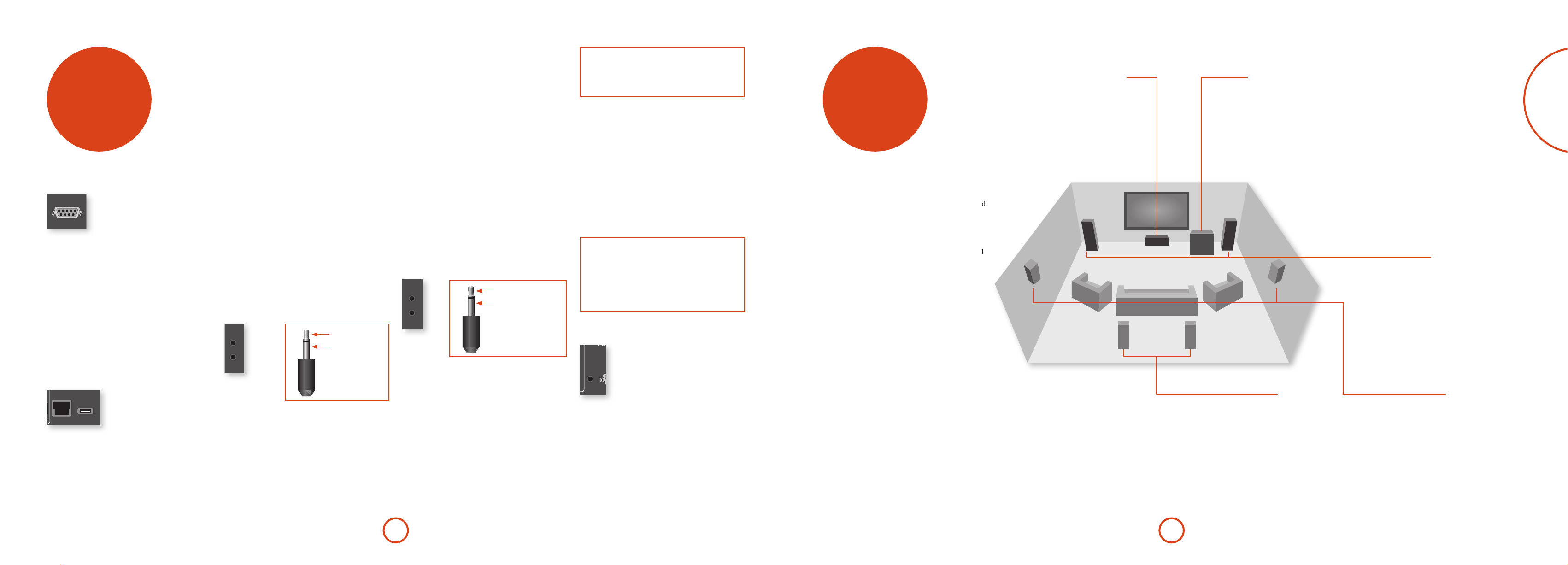
other
speakers
connectors
Serial connector
DNS; see page E-32 for information on setting up the
network.
RS232 serial connector
RS232
e connector is used with control devices having an
RS232 serial port (for example, Crestron and AMX
touch-screen controllers).
Network connector
Networking is a large subject and only the briefest
guidelines are presented in this handbook. Please
contact your Arcam dealer or specialist installer for
more information about introducing the AV950/
AVR750/450/380 into your computer network.
For information on how to use the AV950/
AVR750/450/380’s network features, the USB socket,
and for a list of supported le types, refer to see page
E-37.
ETHERNET
USB 5V / 1A
Ethernet
If an Ethernet cable is connected, the AV950/
AVR750/450/380 will automatically attempt to connect
to your network.
You should use CAT5 cable plugged into the RJ45 socket
labelled ETHERNET on the rear panel.
If your network uses static IP addressing rather than
DHCP, you will need to provide IP address, gateway and
USB connector
e AV950/AVR750/450/380 can play les stored on a
USB mass storage device, typically a pen drive, but any
USB device that complies with the ‘mass storage device‘
class is compatible.
e AV950/AVR750/450/380 only supports the direct
connection of USB devices and will not support devices
connected through a hub. If regular access to the USB
socket is required, you may nd it convenient to use
a USB extension lead; see page E-37 for details of
supported le types.
Trigger connectors
TRIG Z1
TRIG Z2
e trigger connectors (TRIG Z1 and TRIG Z2) provide an
electrical signal whenever the AV950/AVR750/450/380
is switched on and the relevant zone enabled.
e trigger signal can be used to switch on and o
compatible pieces of home entertainment equipment,
for example, you could set up a trigger to turn on
your television and BD player whenever the AV950/
AVR750/450/380 was switched on.
ere are two trigger output sockets on the AV950/
AVR750/450/380, each capable of outputting a 12V,
tip: Trigger output
sleeve: Ground
70mA switching signal. e socket is designed for mono
3.5mm jacks: tip is the trigger output, sleeve is ground.
TRIG Z1
Use for remotely turning on and o power amps or
source equipment for Zone1. On = 12V, O = 0V.
TRIG Z2
Use for remotely turning on and o power amps or
source equipment for Zone2. On = 12V, O = 0V.
Infrared (IR) connectors
Z1 IR
Z2 IR
e infrared inputs (Z1 IR and Z2 IR) allow the
connection of external IR receivers, either when the
AV950/AVR750/450/380 front panel IR receiver is fully
or partially obstructed or to allow the use of a remote
control in Zone2.
ere are two IR inputs on the AV950/AVR750/450/380,
each designed for stereo or mono 3.5mm jacks. Tip is the
modulated signal, sleeve is ground.
Z1 IR
is input is intended for use with a local IR receiver
when the front panel of the AV950/AVR750/450/380 is
blocked.
tip: Modulated signal
sleeve: Ground
Z2 IR
is input is intended for use with an IR receiver
in Zone2 to allow remote control of AV950/
AVR750/450/380 from a second room.
A supplier of infra-red receivers and emitter accessories
and systems is Xantech. See www.xantech.com for
more information, or ask your Arcam dealer.
NOTE
e IR inputs on the AV950/AVR750/450/380 are
designed for modulated signals. If the external IR
receiver demodulates the IR signal, it will not work.
Also the unit does not provide power for external
receivers on the IR jack, therefore an external power
source will be required.
6V output
DC6V
1.2A MAX
is provides a 6V DC power connection for Arcam
rSeries products.
e AVR750/450/380 allows you to connect up to seven
speakers and an active subwoofer in the main system.
e output channels correspond to speakers installed in
the front le, centre, front right, surround le, surround
right, surround back le, surround back right and an
active subwoofer.
e conguration and placement of your speakers
is very important. All speakers, with the exception of
the subwoofer, should be arranged around your normal
viewing/listening position. e subwoofer should be
placed in a position which gives an even frequency
response in all listening positions. Incorrect placement
leads to bass boom in some areas. Oen the only
way to nd a good position for your subwoofer is by
experimentation. A good place to start experimenting
is close to a wall but at least 1m away from any corners.
You can also consult your subwoofer handbook for
placement suggestions.
e centre speaker allows for a more realistic
reproduction of dialogue. e centre speaker
should have a similar tonal balance to the front
le and right speakers and be positioned at a
Centre
similar height.
Subwoofer
A subwoofer will greatly improve the bass performance of your
system. is is useful for reproducing special cinema eects,
especially where a dedicated LFE (Low Frequency Eects)
channel is available, as with many discs encoded with Dolby or
DTS technologies.
More than one subwoofer unit may be required for larger
installations, particularly in rooms of a timber frame
construction. Multiple subwoofers will require a splitter cable
and need care in placement because there may be cancellation
eects between the units and you may require expert advice.
Surround back left and right
e surround back le and right speakers
are used to add extra depth and better
sound localisation and should be installed
approximately one metre higher than the
listener’s ears. Place the two surround
back speakers such that there is an arc of
approximately 150 degrees between each
surround back speaker and the centre speaker.
e surround back speakers should face the front
of the room as shown in the diagram to provide
the largest ‘sweet spot’.
E-15E-14
Front left and right
Position your front le and right speakers to
achieve a good stereo image for normal musical
reproduction as well as for the multichannel
modes. If they are placed too close together there
will be a lack of spaciousness; if they are placed
too far apart a stereo image will appear to have a
large ‘hole’ in the middle and will be presented in
two halves. If there is no practical alternative to
placing the speakers widely apart, this eect can
be overcome in music reproduction by using the
centre sound extraction from the le and right
speakers (see Dolby Pro Logic II Music mode).
Surround left and right
e surround le and right speakers reproduce
the ambient sound and eects present in a
multichannel home cinema system and should be
installed slightly higher than the listener’s ears.
Page 11

English
Connecting speakers
~ 50 – 60 Hz
1.5KW MAX
1.2A MAX TRIG Z2 Z2 IR
TRIG Z1
RS232
DC6V
Z1 IR
OUTPUT1 OUTPUT2AV
AV
ETHERNET
USB 5V / 1A
115 230
FM/DAB
PVR
PVR
VCRBDSAT
AV BD
Y
Pb
Pr
SAT
Z2
VIDEO OUT
GAME PVR
STB BD
PVRSAT
BDCDCD
STB
OPTICAL
COAXIAL
ARC
COMPOSITE
DIGITAL AUDIO
COMPONENT
~ 50 – 60 Hz
1.5KW MAX
1.2A MAX TRIG Z2 Z2 IR
TRIG Z1
RS232
DC6V
Z1 IR
OUTPUT1 OUTPUT2AV
AV
ETHERNET
USB 5V / 1A
115 230
FM/DAB
PVR
PVR
VCRBDSAT
AV BD
Y
Pb
Pr
SAT
SBR SR FR C FL SL SBL
SBR
ZONE 2 R ZONE 2 L
SR FR C FL SL SBL
STBZ2 OUT
Z2
VIDEO OUT
GAME PVR
STB BD
ZONE 2 R
CLASS 2 WIRING
ZONE 2 L
8Ω LOAD IMPEDANCE RECOMMENDED
PVRSAT
BDAV
BDCDCD
GAME
STB
STB
GAME
SPEAKER OUTPUTS
OPTICAL
COAXIAL
ARC
COMPOSITE
DIGITAL AUDIO
ANALOGUE AUDIO
HDMI
COMPONENT
To connect each of the speakers, unscrew the
corresponding terminals on the back of the
AVR750/450/380, insert the speaker wires through the
hole in each post and screw the terminals back up. Make
sure that the red (positive/+) terminal of the speaker is
connected to the red (positive/+) terminal on the back
panel, and the black (negative/–) terminal of the speaker
is connected to the black (negative/–) terminal on the
back panel.
SPEAKER OUTPUTS
ZONE 2 R
SBR SR FR C FL SL SBL
8Ω LOAD IMPEDANCE RECOMMENDED
ZONE 2 L
Bi-amping the Front Left & Front Right speakers
Bi-amping is the use of two amplier channels per speaker. Bi-amping can
provide better sound quality than conventional single wiring. If you do not have
Surround Back speakers (i.e. you have a 5.1 surround system, not a 7.1 system)
then you can use the spare Surround Back speaker outputs to bi-amplify the
front le and right speakers, if your speakers support bi-amping. e spare
channels can alternatively be used to power stereo speakers in another room
(Zone 2).
Speakers that support bi-amping have two sets of +/- terminals per speaker,
usually linked together by metal strips. ese metal strips MUST be removed
when bi-amping; failure to remove them will result in damage to the amplier
that is not covered under warranty.
To bi-amp the front le and right speakers, remove the metal strips from
the speaker terminals. Connect the woofer or LF terminals to the FL and FR
terminals on the AVR750/450/380. Connect the tweeter or HF terminals to the
CLASS 2 WIRING
SBR
SR FR C FL SL SBL
ZONE 2 R ZONE 2 L
SBL and SBR terminals on the AVR750/450/380. Finally, navigate to the Setup
Menu ‘Spkr Types’ and set the ‘Use Channels 6+7 for’ menu option to ‘BiAmp
L+R’; see page E-26.
It is important that no stray strands of wire from these
connections are allowed to touch another cable or the
product casing. Failure to ensure this can cause a short
circuit and damage your AVR750/450/380.
SBR
FR
SBL
FL
Do not over-tighten the loudspeaker terminals, or use a
wrench, pliers, etc., as this could damage the terminals
and this would not be covered under the product’s
warranty.
Link MUST
be removed
Link MUST
be removed
Speaker cables
e speakers should be connected to the amplier using
good-quality, high-purity, low impedance copper cables.
Cheap speaker cables should be avoided – they are a
false economy and can signicantly degrade the sound
quality.
e cable runs to the speakers should be as short as
practicable. Connections to the speaker terminals
should always be nger tight, whether using bare wires
or spade connectors.
Connecting subwoofers
PREAMP OUT
CFL SL SBL
SBRSUBSRFR
e AV950/AVR750/450/380 also allows an active subwoofer to be connected to
the SUB output. Refer to your subwoofer handbook for the correct setting up and
connection procedure for your particular subwoofer.
Using external power amplifiers
e internal power amplier of the AV950/
AVR750/450/380 can be supplemented or replaced with
external power amplication. Connect the PREAMP OUT
sockets to your power amplier inputs:
PREAMP OUT
CFL SL SBL
SBRSUBSRFR
FL, FR, C
Connect these to the equivalent (Right, Le and Centre)
front channels of your power amplier.
SUB
Subwoofer output. Connect this to the input of your
active subwoofer, if present.
SR, SL
Surround Right and Surround Le outputs. Connect
these to the Surround Right and Le power amplier
inputs.
SBR, SBL
Surround Back Right and Surround Back Le outputs
(only used in 7.1 channel systems). Connect these to the
Surround Back Right and Surround Back Le power
amplier inputs.
All preamplier analogue outputs are buered, have
a low output impedance and are at line level. ey are
able to drive long cables or several inputs in parallel if
required.
operation
Operating your AV950/
AVR750/450/380
For information display we recommend you use the
OSD (On-Screen Display) on your display device
whenever possible.
Switching on
Press the front panel power button in. e power
LED will glow green, the front display shows the word
‘ARCAM’. When initialisation is complete, the display
shows the volume setting and the name of the selected
input.
Please wait until the unit has nished initialising
before operating the AV950/AVR750/450/380. It is
recommended that if the unit is switched o, you should
wait at least 10 seconds before switching the unit back
on.
Standby
e AV950/AVR750/450/380 has a standby mode which
can be entered by pressing STANDBY on the remote
control. When in standby mode, the display is blank and
the POWER LED glows red.
If the unit is to be le unused for an extended period,
we recommend that you disconnect it from the mains
supply to save power.
To switch on from standby
Press the STANDBY button on the remote control or any
key on the front panel (other than the power button).
Front panel display
e AV950/AVR750/450/380 is ready for use aer about
four seconds.
BD 37
e display window shows the currently selected source
and the last selected information view setting (this
information line can be changed using the INFO button).
e current volume setting for Zone 1 (37.0dB in the
above example) is displayed on the front panel. e
volume setting for Zone 2 is displayed temporarily
whenever it is adjusted.
Selecting a source
To select a particular source, press the –INPUT or
INPUT+ buttons until that source is shown on the front
panel display, or (if available) press the corresponding
source button on the remote. e following sources are
available:
STB
GAME
AV
SAT
BD
VCR
PVR
CD
FM
DAB
NET
USB
AUX
DISPLAY
Most audio inputs have both analogue and digital
connections. You must specify the type of connection
used for each input using the ‘Audio Source’ option in
the ‘Input Cong.’ menu, see page E-29. Note that an
incorrect setting will result in no sound — the default is
HDMI audio. If you are not using HDMI audio then this
setting must be changed.
e processing mode and Stereo Direct functions are
remembered and recalled for each individual input.
Stereo Direct
To listen to a pure analogue stereo input, press the
DIRECT button. e Stereo Direct mode automatically
bypasses all processing and any surround functions. In
direct mode, digital processing is shut down to improve
Set Top Box input
Game console input
Audio-Visual input
Satellite input
Blu-ray Disc/DVD player input
Video Cassette Recorder input
Personal Video Recorder input
Compact Disc player input
Internal tuner input
Internal tuner input (this source
is market dependent and may
not be available on your AV950/
AVR750/450)
Ethernet input
External USB solid-state device (e.g.
pen drive, iPad) input
Auxiliary (front panel) input
e Audio Return Channel (ARC)
from an HDMI 1.4-compliant display.
Use this with an HDMI 1.4-compliant
television using internal TV tuners.
the sound quality and reduces digital noise with the
AV950/AVR750/450/380 to an absolute minimum.
Note: when Stereo Direct mode is selected, no
digital output is available and no bass management
is performed, meaning that bass signals will not be
redirected to a subwoofer.
Volume control
It is important to realise that the level of the volume
indicator is not an accurate indication of the
power delivered to your loudspeakers. e AV950/
AVR750/450/380 oen delivers its full output power
long before the volume control reaches its maximum
position, particularly when listening to heavily recorded
music. In comparison, some movie sound tracks
can appear very quiet, as many directors like to keep
maximum levels in reserve for special eects sequences.
Headphones
To use headphones with the AV950/AVR750/450/380,
plug the headphones into the PHONES socket in the
centre of the front panel.
When headphones are plugged into the front panel
PHONES socket, the outputs for Zone1 are muted and
the audio will be down-mixed to two channels (2.0). e
two-channel down-mix is required so that the centre
E-17E-16
Page 12

English
channel and surround information can be heard via the
headphones.
Using Zone 2
Zone2 provides the option for the occupants of the
master bedroom, conservatory, kitchen, etc. to view or
listen to a dierent source at a dierent volume level
from the main zone (Zone1).
Source selection and volume control for Zone 2 is
achieved:
by using an IR receiver in Zone 2 (see “Zone2
<
control connections” on page E-38), or
by switching over to Zone 2 control by pressing the
<
front panel zone button, or
by pressing AMP + OK on the remote control.
<
e front panel VFD display indicates that control has
been switched to Zone 2.
STANDBY Z2 50
To turn on Zone 2, press the Zone button (or AMP +
OK) then press the standby power button on the remote
control. Press a source select button to select a dierent
source to Zone 1.
FOLLOW Z1 Z2 50
Note that Zone 2 control from within Zone 1 will pass
automatically back to Zone 1 control aer a few seconds
of inactivity.
Zone 2 can also be controlled using a third-party
programmable remote control or a home automation
system. Please contact your dealer or installer for
further details.
Extended front panel menu
Pressing the MENU key and holding it for longer than
four seconds will bring up the Extended Menu, allowing
you to perform the following:
Restore to factory defaults
is option allows you to restore all settings on your
AV950/AVR750/450/380 to the defaults that it le the
factory with.
Change remote code
e default RC5 system code the AV950/
AVR750/450/380 responds to is 16. If required, for
example due to another device in your system also using
this RC5 system code, it can be changed to 19.
Restore secure backup
is option allows you to restore all settings to their
state as saved using the ‘Store secure backup’ feature.
is option is useful if settings are accidentally changed.
It also allows the unit to be returned to the saved state
following a rmware update.
Store secure backup
is option allows you to save all the AV950/
AVR750/450/380 settings to a secure area of memory.
e settings can be retrieved using the Restore option
above.
– Enter PIN
Enter the secure backup PIN using the ', ,, <
and > keys on the remote control (do not use the
numeric keypad). The default PIN is 1234.
– Change PIN
Allows the PIN to be changed to a number other
than the default. Enter the current secure backup
PIN using the ', ,, < and > keys on the
remote control (do not use the numeric keypad).
The default PIN is 1234. After the current PIN has
been entered correctly, enter a new PIN as prompted
and again to confirm.
– EXIT
Cancel and return to the extended menu.
Updating firmware via USB
e rmware in your AV950/AVR750/450/380 can be
updatedfromaUSBashdrivecontainingarmware
update le.
You can download the latest rmware le, together
with upgrading instructions, from the Arcam website
(www.arcam.co.uk/advice-and-support.htm).
front panel
operation
Input
ese buttons select the source
connected to the corresponding
input (or internal input)
Unused sources can be prevented
from being selected in the setup
menu.
Selects between Stereo and the available
surround modes for the current source.
Selects the information displayed on the
lower le portion of the front panel.
Used to enter selections made in the
Setup menu. Press and hold to reset
video outputs to the lowest resolution
AVR750
Selects the Setup menus on the
on-screen display (OSD).
Menu
Mode
Info
OK
(HDMI: 480p).
Aux
Multi purpose auxiliary
line level input,
calibration microphone
input and 3.5mm optical
digital (SPDIF) input.
Direct
Stereo Direct on/o. Provides a direct analogue path from
the analogue inputs to the le and right front outputs.
Switches o any surround processing modes and shuts
down the DSP circuits for best stereo sound quality.
Display
is switches the display brightness
between o/dim/bright.
Zone
Selects between Zone1 and
Zone2 control.
Mute
Mutes all analogue audio outputs in the
currently selected zone.
Phones
is socket accepts headphones
with an impedance rating between
32Ω and 600Ω, tted with a 3.5mm
stereo jack plug.
Power / Standby LED
is indicates the status of the receiver and is
green when the AV950/AVR750/450/380 is
powered on. Red indicates the unit is in Standby
mode.
Volume
Adjusts the analogue output
volume in the selected zone
(line out, speakers and
headphones).
Power
Switches the main power to the
AV950/AVR750/450/380 on
and o.
Once the unit is switched o,
it should be le for at least ten
seconds before switching on
again.
Remote control receiver. is is positioned behind
the display window, above the MENU button on the
front panel. Ensure the receiver is in a clear line of
sight from the remote control for operation. If this is
not possible, use a separate sensor connected to the
Z1 IR input on the rear panel.
E-19E-18
Page 13
English
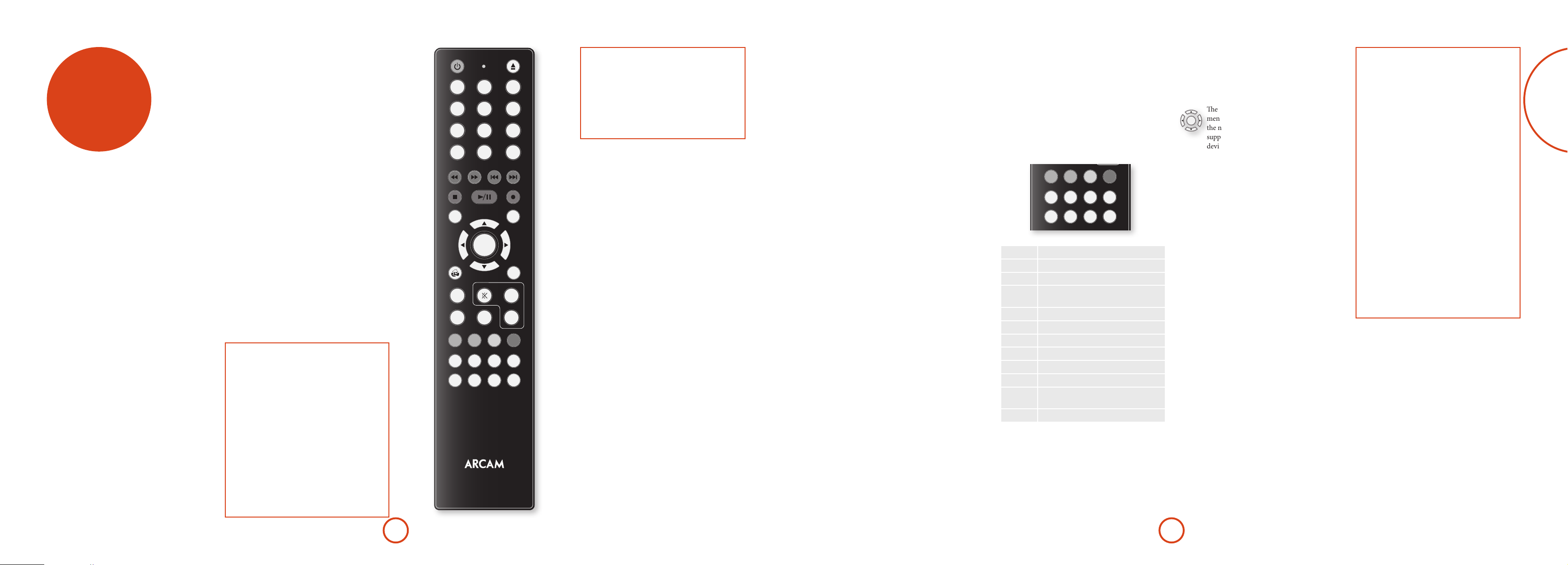
remote
1
2
3
4
5
6
7
8
9
0
OK
RTN
VOL+
VOL-
FAV+ FAV-
INFO
MENU
DIRECT
EFFECT
BASS
TREB
TRIM
SYNC
DISP MODE
DISC MENU POP UP
SUBT
AUDIO
AMP
SUB
EQ
RPT
abc def
ghi jkl mno
pqrs tuv
wxyz
control
The CR450 universal remote
controller
e CR450 is a sophisticated ‘universal’ backlit remote
control that can control up to eight devices. It is preprogrammed for use with the AV950/AVR750/450/380
and many other Arcam products (FM/DAB tuners, CD
players and DVD players).
With its extensive built-in library of codes, it can also
be used with thousands of third party audio-visual
components – TVs, satellite and set-top boxes, PVRs,
CD players, etc. See the list of codes at the back of this
handbook, beginning on page 49.
e CR450 is a ‘learning’ remote, so you can teach it
almost any function from an old single-device remote.
Using the remote control
Please keep in mind the following when using the
remote control:
< Ensure there are no obstacles between the
remote control and the remote sensor on the
AV950/AVR750/450/380. e remote has a
range of about 7 metres. (If the remote sensor is
obscured, the Z1 IR remote control input jack
on the rear panel is available. Please consult
your dealer for further information.)
< Remote operation may become unreliable
ifstrongsunlightoruorescentlightis
shining on the remote sensor of the AV950/
AVR750/450/380.
< Replace the batteries when you notice a
reduction in the operating range of the remote
control.
EQ
2
1
abc def
5
4
ghi jkl mno
7
pqrs tuv
DISP MODE
FAV+ FAV-
SYNC
DISC MENU POP UP
INFO
8
0
EFFECT
TRIM
3
6
9
wxyz
RPT
DIRECT
SUB
MENU
OK
RTN
AUDIO
BASS
SUBT
TREB
STB
AUX
AV
SAT
CR450
AMP
VOL+
VOL-
USBTUN NET
VCRBD
GAME
CDPVR
Inserting batteries into the
remote control
1. Open the battery compartment on the back of
the handset, by sliding its cover o.
2. Insert two ‘AAA’ batteries, as indicated in the
battery compartment.
3. Slide the battery compartment cover back rmly
into its locked position with a click.
Notes on batteries:
Incorrect use of batteries can result in hazards such
<
as leakage and bursting.
Do not mix old and new batteries together.
<
Do not use non-identical batteries together –
<
although they may look similar, dierent batteries
may have dierent voltages.
Ensure the plus (+) and minus (-) ends of each
<
battery match the direction indicated in the battery
compartment.
Remove batteries from equipment that is not going
<
to be used for a month or more.
When disposing of used batteries, please comply
<
with governmental or local regulations that apply in
your country or area.
Useful information
Backlight
A backlight comes on for eight seconds whenever a key
is pressed. is helps you use the handset in subdued
lighting conditions.
Power LED blinks
Short blinks indicate a valid key press.
Multiple short blinks convey information (such as a
device code) or signal the beginning and successful
completion of a programming sequence.
e symbol ‘*’ is used in the manual to indicate a
power LED blink.
Timeouts and unassigned keys
Time out – Aer 30 seconds the CR450 exits the
programming state and returns to normal operation.
Stuck key timeout – Aer any key is pressed
continuously for 30 seconds, the CR450 stops sending
IR transmission to conserve battery life. e CR450
remains o until all keys are released.
Unassigned keys – the CR450 ignores any unassigned
key presses for a particular Device Mode and does not
transmit IR.
Low voltage indicator
Whenthebatteriesarerunningdown,theLEDashes
ve times whenever you press a button:
* * * * *
If this happens, t two new AAA alkaline batteries as
soon as possible.
Device Mode / Source keys
As the CR450 can control your AV950/AVR750/450/380
as well as a range of other equipment: many of the
buttons have more than one function depending on the
‘device mode’ selected on the remote control.
e Device Mode keys (shown below) select the source
on the AV950/AVR750/450/380. If one of these keys is
pressedbriey,acommandistransmittedtochangethe
source on the unit. Also the functionality of the remote
control changes to operate the selected source device; it’s
like having a bundle of dierent remotes in your hand!
AUX
AV
SAT
STB
Internal FM or DAB tuner input
T
Auxiliary input
x
Ethernet input (e.g. Internet radio)
N
External USB device (iPod, iPhone,
y
audio les on pen drive, etc.)
Blu-ray Disc or DVD player
B
Audio-visual sound input (use with TV)
a
Video Cassette recorder input
w
Games console input
G
Set Top Box decoder input
C
Satellite input
z
Personal Video Recorder (or Digital
v
Video Recorder) input
Compact Disc player input
c
Each Device Mode changes the behaviour of many
of the CR450 keys to control the source device
appropriately. For example: in CD mode ) plays the
previous CD track, but in AV mode ) issues the TV
‘channel down’ command.
e CR450 remains in the last selected Device Mode
so it is not necessary to press a Device Mode key before
USBTUN NET
VCRBD
GAME
CDPVR
every command key if all you are doing is playing or
skipping tracks on a CD, for example.
Pressing the C or G keys puts the remote into AMP
device mode.
Navigation keys
e Navigation keys steer the cursor in Setup
menus or on-screen menus. ey also replicate
OK
the navigation functions of original remotes
supplied with other home entertainment
devices in your system. O conrms a setting.
Volume control
By default, the CR450 is set up so that the volume
control and mute buttons (", / and @) always
control the volume of the AV950/AVR750/450/380,
regardless of which Device Mode the remote is currently
set for. is is known as volume ‘punch through’.
For example, if you are listening to a CD, you will
probably have the CR450 in CD Device Mode to control
the CD player. You can use the volume controls on the
remote directly to adjust the volume of the AV950/
AVR750/450/380 without rst having to press A to put
the remote into AMP Device Mode. e volume buttons
‘punch through’ the CD Device Mode on the remote to
the AMP Device Mode.
Volume ‘punch through’ can be disabled individually for
any Device Mode if desired.
Customising the CR450
e CR450 oers a Code Learning feature that allows
you to copy up to 16 functions from an original remote
control onto the CR450 keypad. For details of this,
and other customisation features, see “customising the
CR450” on page E-40.
The CR450 complies with Part 15 of the
FCC rules
is equipment has been tested and found to
comply with the limits for a class B digital device,
pursuant to part 15 of the FCC Rules. ese limits
are designed to provide a reasonable protection
against harmful interference in a residential
installation. is equipment generates, uses, and can
radiated radio frequency energy and if not installed
and used in accordance with the instructions,
may cause harmful interference to radio
communications. However, there is no guarantee
that interference will not occur in a particular
installation. If this equipment does cause harmful
interference to radio or television reception, which
can be determined by turning the equipment o
and on, the user is encouraged to try to correct
the interference by one or more of the following
measures:
Reorient or relocate the receiving antenna.
Increase the separation between the equipment and
receiver.
Connect the equipment into an outlet or a circuit
dierent from that to which the receiver is
connected.
Consult the dealer or an experienced radio/TV
technician for help.
E-21E-20
Page 14

English
AMP
AMP Device Mode
e A Device Mode button congures the CR450
to control the AV950/AVR750/450/380. Pressing this
button does not aect the currently selected input on the
AV950/AVR750/450/380.
IMPORTANT: e CR450 must also be in AMP Device
Mode to control the following sources: BD, AV, VCR,
GAME, STB, SAT , PVR or CD.
e functionality of the CR450 is context sensitive for
the internal sources and is described in the following
table.
Single press – Toggles AV950/
P
AVR750/450/380 power between standby
and on in the current zone (zone in which
the command is received).
Press and hold – Forces all zones into
standby, regardless of which zone the
command was received in.
EQ
Displays the room EQ settings menu.
!
0…9
e number keys can be used for source
selection (without changing the CR450
Device Mode). Alternatively, the Device
Mode buttons can be used with the m ke y.
SAT (satellite) input
0
STB input
1
AV input
2
TUNER input
3
BD input
4
GAME input
5
VCR input
6
CD input
7
AUX (front panel) input.
8
Cycles through the front panel display’s
D
brightness options
RPT
Cycles through the available surround and
downmix modes.
M
FAV+
Rewind.
Adds the currently displayed radio station
)
to favourites list when using the internet
radio function.
TRIM
Brings up the speaker trim menu.
Y
Use the '
and > navigation
, <
buttons. Press TRIM again to exit the speaker
trim menu.
As this is a temporary adjustment, these
trim levels are reset to zero when the
unit is turned o or put into standby,
but are retained if the selected input is
changed. ese temporary trim levels are
independent of the speaker levels found in
the setup menu.
DIRECT
Stereo direct on/o. Provides a direct
analogue path from the analogue inputs to
Z
the le and right front outputs. Switches o
any surround processing modes and shuts
down the DSP circuits for the best stereo
sound quality.
SYNC
Sync. Delays may be introduced into the
video signal by video processing which
#
causes a mismatch between the audio and
video timing. You will notice this by speech
sound being out of synchronization with the
lip movements in the video. To compensate
for this, you can adjust the lip sync delay.
Press the SYNC button and use the D and E
navigation buttons. Press again to exit the
lip sync trim menu.
EFFECT
Toggles Dolby Volume on/o.
;
SUB
Brings up a temporary subwoofer trim
control. Use the D and E navigation
%
buttons. Press SUB again to exit the sub trim
control.
As this is a temporary adjustment, the
sub trim level is reset to the value set in
the Speaker Levels menu when the unit is
turned o or put into standby.
DISC MENU
Info cycles through the information
displayed on the lower le portion of the
i
front panel display when on TUN, NET and
USB inputs.
POP UP
Displays the unit’s setup menu on the On
Screen Display.
U
Navigate the files and menus on the screen.
OK
OK selects the highlighted file or enters the
highlighted menu on the screen
to ‘Enter’ or ‘Select’ on some remote
controls.
Up
'
Le
<
Right
>
Down
,
+ ' Power on from standby
A
+ , Standby from Power on
A
+ O select Zone 2
A
+ > changes the picture resolution.
A
Returns navigation to the top level of the
.
network client menus (‘Home’).
AUDIO
Calls up a pop-up to adjust the bass setting
for a particular input.
g
Toggles the mute function of the AVR.
@
Increase amplier volume.
"
SUBT
Calls up a pop-up to adjust the treble setting
for a particular input.
f
Resets remote to AMP mode.
A
Decrease amplier volume.
/
Tuner / Red button.
T
Aux / Green button.
x
Network (NET) internal input / Yellow
N
button.
USB / Blue button.
y
BD/DVD input.
B
AV input.
a
VCR input.
w
Game console input.
G
Set top box input.
C
Satellite input.
z
PVR input.
v
CD input.
c
– equivalent
USB commands
e USB interface is selected by pressing y in AMP
Device Mode on the CR450. When connected to an
iPod or other device storing music les connected by
USB, the keys below are used to navigating music tracks.
Navigates the les on screen.
TRIM
Y
DIRECT
OK
selects/plays the highlighted le.
O
Selects the previous/next track in the
current playlist.
Z
EFFECT
Toggles pause and playback of the current
track.
;
Stops playback..
#
Network commands
When using the network client, the keys below are used
to navigate music les in AMP Device Mode.
Navigates the les on screen.
OK
TRIM
Y
DIRECT
Z
EFFECT
;
#
FAV+
)
FAV–
(
.
selects/plays the highlighted le.
O
Selects the previous/next track in the
current playlist.
Toggles pause and playback of the current
track.
Stops playback..
Adds the currently displayed le or radio
station to the favourites list when using the
network client.
Removes the currently displayed le or
radio station to the favourites list when
using the network client.
Returns navigation to the top level of the
network client menus (‘Home’)
BD
BD/DVD Device Mode
e d Device Mode button congures the CR450 to
control the functions of Arcam Blu-ray Disc and DVD
players, although this can be changed. Pressing this
button also selects BD as the source.
Toggles power between standby and on.
P
EQ
Open/close disc tray.
!
0…9
Searches for and plays the track
corresponding to the key pressed when
playing a CD.
Cycles through the front panel display’s
D
brightness options.
RPT
Cycles through the repeat options (track,
disc, etc.).
M
FAV+
Fast rewind.
)
FAV–
Fast forward.
(
TRIM
Press and release to skip back to the
beginning of the current/previous track.
Y
DIRECT
Press and release to skip forwards to the
beginning of the next track.
Z
Stereo direct on/o. Provides a direct
analogue path from the analogue inputs to
the le and right front outputs. Switches o
any surround processing modes and shuts
down the DSP circuits for the best stereo
sound quality.
SYNC
Stop playback of a BD or DVD.
#
EFFECT
Toggles pause and playback of the current
track.
;
SUB
Start recording (on products that have this
feature).
%
DISC MENU
Disc menu.
i
POP UP
Activates BD/DVD player menu, if
available.
U
Navigate setup and BD/DVD programme
OK
selection menus.
selects the highlighted file or enters the
O
highlighted menu on the screen
to ‘Enter’ or ‘Select’ on some remote
controls.
Up
'
Le
<
Right
>
Down
,
+ ' Power on from Standby
B
+ , Standby from Power on
B
+ > changes the picture resolution (for
B
BD, only on the Home screen).
Returns navigation to the top level of the
.
menu (‘Home’).
AUDIO
Changes audio decode format (Dolby
Digital, DTS, etc.).
g
SUBT
Cycles through subtitle options, if available.
f
Resets remote to AMP mode.
A
RED button for BD
T
GREEN button for BD
x
YELLOW button for BD
N
BLUE button for BD.
y
– equivalent
AV
AV Device Mode
e a Device Mode button congures the CR450 to
control the functions of a television or other display
device. You will need to congure this Device Mode to
work with your equipment. Pressing this button also
selects AV as the source.
Toggles power between standby and on.
P
(Some TVs require you to use a number key
to turn them on).
0…9
Functions as original remote number key –
usually for channel selection.
Display INFO or OSD (On Screen Display)
D
function, if available.
RPT
AV; this function is TV specic.
M
TRIM
Channel down.
Y
DIRECT
Channel up.
Z
DISC MENU
Displays picture information; this function
is TV specic.
i
POP UP
Guide.
U
Navigate setup and programme selection
OK
menus.
conrms a selection (equivalent to
O
‘Enter’ or ‘Select’ on some remotes).
Returns navigation to the top level of the
.
menu (‘Home’).
SUBT
Cycles through subtitle options, if available.
f
Resets remote to AMP mode.
A
RED key for Text TV
T
GREEN key for Text TV
x
YELLOW key for Text TV
N
BLUE key for Text TV.
y
VCR
VCR Device Mode
e w Device Mode button selects VCR as the source.
e VCR page allows code learning from a dedicated
VCR remote – see “customising the CR450” on page
E-40.
E-23E-22
Page 15

English
STB
STB Device Mode
e C Device Mode button selects STB as the source.
If congured to work with your set top box decoder or
similar device, the CR450 can subsequently control the
device.
SAT
SAT Device Mode
e z Device Mode button selects SAT as the source.
If congured to work with your satellite receiver, the
CR450 can subsequently control the device.
PVR
PVR Device Mode
e v Device Mode button selects PVR as the source.
If congured to work with your personal (hard disc)
video recorder or similar device, the CR450 can
subsequently control the device.
CD
CD Device Mode
e c Device Mode button selects CD as the source.
e button is congured to control the CD functions of
Arcam CD players, although this can be changed (see
“Locking/Unlocking a specic Device Mode” on page
E-41).
P
0…9
D
RPT
M
FAV+
)
FAV–
(
TRIM
Y
DIRECT
Z
SYNC
#
EFFECT
;
SUB
%
DISC MENU
i
POP UP
U
OK
.
Toggles power between standby and on.
Functions as original remote number key –
usually for channel selection.
Display INFO or OSD (On Screen Display)
function, if available.
Selects the Library or Media function.
Rewind.
Fast Forward.
Channel down.
Channel up.
Stop playback.
Toggles pause and playback of the current
track.
Record.
Opens the EPG (Electronic Program Guide)
on some satellite and cable set top boxes.
Turns on the Menu function if the set top
box uses this feature.
Navigate setup and programme selection
menus.
conrms a selection (equivalent to
O
‘Enter’ or ‘Select’ on some remotes).
Returns navigation to the top level of the
menu (‘Home’).
AUDIO
Selects the Help function.
g
SUBT
Cycles through subtitle options, if available.
f
Resets remote to AMP mode.
A
RED button for set top box.
T
GREEN button for set top box.
x
YELLOW button for set top box.
N
BLUE button for set top box.
y
P
0…9
D
TRIM
Y
DIRECT
Z
DISC MENU
i
POP UP
U
OK
.
q
SUBT
f
A
T
x
N
y
Toggles power between standby and on.
Functions as original remote number key –
usually for channel selection.
Display INFO or OSD (On Screen Display)
function, if available.
Channel down.
Channel up.
Displays programme information.
Guide (or Setup on some set top boxes).
Navigate setup and programme selection
menus.
conrms a selection (equivalent to
O
‘Enter’ or ‘Select’ on some remotes).
Returns navigation to the top level of the
menu (‘Home’).
Back.
Cycles through subtitle options, if available.
Resets remote to AMP mode.
RED button for Satellite.
GREEN button for Satellite.
YELLOW button for Satellite.
BLUE button for Satellite.
P
0…9
D
RPT
M
FAV+
)
FAV–
(
TRIM
Y
DIRECT
Z
SYNC
#
EFFECT
;
SUB
%
DISC MENU
i
POP UP
U
OK
.
Toggles power between standby and on.
Functions as original remote number key –
usually for channel selection.
Display INFO or OSD (On Screen Display)
function, if available.
Selects the Library or Media function.
Rewind.
Fast Forward.
Channel down.
Channel up.
Stop playback.
Toggles pause and playback of the current
track.
Record.
Opens the EPG (Electronic Program Guide)
on some satellite and cable set top boxes.
Turns on the Menu function if the PVR uses
this feature.
Navigate setup and programme selection
menus.
conrms a selection (equivalent to
O
‘Enter’ or ‘Select’ on some remotes).
Returns navigation to the top level of the
menu (‘Home’).
AUDIO
Selects the Help function.
g
SUBT
Cycles through subtitle options, if available.
f
Resets remote to AMP mode.
A
RED button for PVR.
T
GREEN button for PVR.
x
YELLOW button for PVR.
N
BLUE button for PVR.
y
P
EQ
!
0…9
D
RPT
M
FAV+
)
FAV–
(
TRIM
Y
DIRECT
Z
SYNC
#
EFFECT
;
POP UP
U
Toggles power between standby and on.
Open/close disc tray.
Searches for and plays the track
corresponding to the key pressed.
Cycles through the front panel display’s
brightness options.
Cycles through the repeat options (track,
disc, etc.).
Fast rewind.
Fast forward.
Press and release to skip back to the
beginning of the current/previous track
Press and release to skip forwards to the
beginning of the next track.
Stop playback of a CD
Toggles pause and playback of the current
track.
In ‘normal play’ (i.e. the display does not
show the letter P), press the ' and '
keys to select the track and then U stores
the track.
In ‘program play’ mode, the U key deletes
the stored track.
Navigate setup and CD programme
OK
selection menus.
selects the highlighted file or enters the
O
highlighted menu on the screen
to ‘Enter’ or ‘Select’ on some remote
controls.
Up
'
Le
<
Right
>
Down
'
+ ' Power on from Standby
c
+ , Standby from Power on.
c
Resets remote to AMP mode.
A
Plays the programmed tracks.
T
– equivalent
E-25E-24
Page 16

English
essential
setup
Before you use your AV950/AVR750/450/380 it is
essential that you enter some information into the Setup
menus about your speaker conguration. is allows the
AV950/AVR750/450/380 to process any surround sound
digital source to exactly match your system and give you
the ultimate surround sound experience.
ere are three pieces of vital information which are
outlined in the sections: ‘Speaker Types’, ‘Speaker
Distances’ and ‘Speaker Levels’.
e way you enter this information manually into the
AV950/AVR750/450/380 is given later in the ‘Setup
Menus’ section on page E-28. e settings can also be
established automatically using the Arcam Auto Speaker
Setup function. However it is important to understand
why these speaker settings must be entered, which is
why this section is presented rst.
Speaker types
You need to set the type of speakers that you have
connected to your AV950/AVR750/450/380:
Large capable of full frequency range reproduction
Small not capable of full frequency range
reproduction at the low frequency end
None speaker not present in your configuration
e terms ‘Large’ and ‘Small’ do not necessarily relate to
the physical size of your speakers. As a rule of thumb,
ifaspeakercannotreproduceaatfrequencyresponse
down to about 40Hz (and very few can!) it is oen better
to consider them as ‘Small’ for setup purposes of home
cinema.
When a speaker is set to ‘Small’, very low frequency
sounds are redirected away from that speaker to a ‘Large’
speaker or a subwoofer, which are far better suited to
reproducing these low frequency sounds.
Note that it is not possible to set all speakers to
‘Small’ unless there is a subwoofer in your speaker
conguration. If you do not have a subwoofer, you will
be forced to set your front speakers to ‘Large’.
(Advanced users may wish to automatically override the
‘Small’ speaker setting for purely stereo music listening
when not watching movies. is can be achieved in the
‘Input Cong.’ menu – see page E-29.
Crossover frequency
If you have set any speakers as being Small, then you will
be required to set a value for the crossover frequency.
is is the frequency below which signals are ltered
away from these Small speakers and redirected to Large
speakers or the subwoofer (if present). A frequency of
80Hz is oen a good starting point, however you will
probably have to experiment with dierent values to nd
the best value for your system or consult your speaker
handbook.
Use Channels 6+7 for
If not used in the main zone, it is possible to assign the
Surround Back channels to bi-amp the Front Le/Right
channels or to provide an amplied output to Zone2.
Speaker Distances
It is essential for the distance from each speaker to the
listening position to be accurately measured and entered
into the ‘Setup’ menu. is ensures that the sounds from
the various speakers arrive at the listening position at
the correct time to recreate a realistic surround eect.
e distance can be entered in centimetres or inches.
Speaker Levels
Finally the levels of all the speakers in the system need
to be adjusted to match each other at the listening
position, again to create a proper surround eect. To
help with this the AV950/AVR750/450/380 can generate
a test noise for each speaker which should be measured
with a sound pressure level (SPL) meter. e meter
should be set to ‘C’ weighting and slow response. e
level of noise measured at the listening position from
each speaker should be adjusted on the Speaker Trims
page of the Setup menu so that the meter reads 75dB
SPL. It does not matter what the system volume setting
of the AV950/AVR750/450/380 is before turning the
test noise on as the volume setting is over-ridden for the
duration of the speaker noise test.
ere are several basic SPL meters on the market at
reasonable prices aimed at home cinema enthusiasts.
Check your local technology store, search online or ask
your dealer.
If you do not have an SPL meter, you can try to adjust
the noise level of each speaker by ear. In this case it is
not possible to adjust the speakers to the absolute 75dB
SPL volume level, but you should aim for all speakers
sounding equally loud. Setting speaker test noise levels
byearisnotrecommendedasitisverydiculttodo
accurately, but is oen better than doing nothing at all!
auto speaker
setup
NOTE
Auto calibration is possible only for a 7.x, 5.x or 4.x
speaker conguration. Other speaker congurations,
such as a 2.1 setup (le, right and subwoofer),
must be congured manually using the speaker
conguration menus (see page E-31), referring
to the guidelines on page E-26 for speaker types,
speaker distance and speaker levels.
ere is a proprietary automatic loudspeaker setup
function built into your AV950/AVR750/450/380. e
Arcam Auto Speaker Setup function attempts to set
all the essential speaker settings for all the speakers in
your system. It also calculates room equalisation (Room
EQ) lter values to remove some of the worst eects of
resonant frequencies in the listening room.
Your AV950/AVR750/450/380 package is supplied with
a calibration microphone, which should be inserted into
the AUX jack socket on the front panel and positioned
at the main listening position. is microphone picks
up the special calibration tones generated by the
speakers when Auto Speaker Setup is run. e AV950/
AVR750/450/380 then analyses the signal and computes:
which speakers are present,
<
speaker type,
<
speaker distance,
<
speaker level,
<
crossover frequency to the subwoofer (or large front
<
speakers if no subwoofer is present),
problem resonant frequencies in the room which
<
need control by ltering.
To help the system be as accurate as possible when
performing Auto Speaker Setup, there are a few
guidance rules that should be followed:
Minimise any background sounds in the listening
<
room and other nearby rooms.
Close all windows and doors in the listening room.
<
Turn o all fans including air-conditioning systems.
<
If holding the microphone in the hand rather than
<
mounting on a tripod or similar, keep your hand and
ngers still to avoid generating ‘handling noise’.
Position the set up microphone pointing upwards at
<
roughly head height in the normal listening position.
It is not necessary to point the microphone directly
at the speaker generating the test tone. (It helps if
you are able to position the microphone exactly
where your head would normally be for listening,
with the microphone in direct unobstructed view of
all speakers.)
If your system includes an active subwoofer, start
<
by setting its output level / gain control to a value
halfway between maximum and minimum.
When activated, a calibration tone is played through
each channel of the AV950/AVR750/450/380 in turn,
including the subwoofer channel. e calibration tone
cycles round each of the speakers multiple times as the
dierent parameters are calculated. If you do not have
a full 7.1 speaker conguration there will be periods
of silence between some speaker channels. Follow the
‘progress’ information on-screen.
Aer all the channels have been measured, a summary
of the speaker conguration will be displayed on-screen.
You can then choose to accept the settings, re-measure
your system again or cancel Auto Speaker Setup without
storing the settings.
e Auto Speaker Setup function is found within the
Setup menus, see page E-30. By default, Room EQ is
not applied to any of the source inputs. You should
enable Room EQ on inputs you think benet from this
feature, as required, by listening when playing typical
source material through each input. is is enabled from
within the Input Cong menu.
While room equalisation can help to reduce problems
with listening room acoustics, it is usually far better
to try to solve these problems with the room directly.
Proper loudspeaker positioning, acoustic wall
treatments and moving the listening position away from
walls should produce far better results overall. However
itmaybediculttodothisinahomeenvironment,so
Room EQ is your next best choice.
Problems
We advise you to look over the reported measurements
on the screen following Auto Speaker Setup for any
obviously incorrect results, in particular to ensure the
reported speakers match your conguration and that the
speaker distances to the listening position appear look
roughly correct. If the results are not what you expected
re-run Auto Speaker Setup.
e Auto Speaker Setup function is normally quite
accurate but occasionally false results can be generated.
Problems may be as a result of:
external sounds or rumbling / handling noises
<
picked up by the microphone
soundreectionsohardsurfaces(e.g.windowsor
<
walls) close to the listening position,
very strong acoustic resonances within the room,
<
obstacles (such as a sofa) between speakers and the
<
microphone.
Ifyouarestillexperiencingdicultiesoryouwishto
have the most accurate results for ultimate surround
performance, we recommend using the manual method
of establishing speaker distances and levels.
Using a subwoofer
If your system includes an active subwoofer you may
need to re-run Auto Speaker Setup with the subwoofer
output level / gain control set to a higher or lower value,
if the summary screen reports problems setting the
subwoofer up.
Auto Speaker Setup will attempt to choose a crossover
frequency that allows the smoothest low frequency
transition from the main speakers to the subwoofer.
However if this does not produce pleasing results we
recommend manually trying other crossover frequencies
to nd something more to your preference.
See the next sections for information of how to enter or
change speaker settings manually.
E-27E-26
Page 17

English
setup menus
e Setup menus allow you to congure all aspects of
your AV950/AVR750/450/380. e next few pages will
go through the menu items and explain their function.
e Setup menus will probably look quite daunting if
you are new to setting up home cinema, but the majority
of them need only be congured once when you rst
install the system (or if your system changes or you
move house!)
e only way to view the Setup menus is on your display
device (TV or projector) using the on-screen display
(OSD) capability of the AV950/AVR750/450/380. To
view the OSD for the initial setting up, connect any of
the video outputs to your display device. You do not
need to have a video source connected to the AV950/
AVR750/450/380 video inputs.
Entering Setup mode
To enter the setup menu, press the MENU button on the
remote control or font panel. e front panel display
shows ‘SETUP MENU’ and the setup menu (pictured
right) is displayed.
Unstable OSD menu or picture display?
e default AV950/AVR750/450/380 output video
resolution when rst powered up out of the box is
‘Preferred’ for digital video. is has been chosen
as most display devices can synchronise to this
automatically. is can be changed in the Video Outputs
section of the Setup Menus.
If the output resolution and frame rate is forced to a
setting your display device does not support, the picture
may become unstable or may not display at all. To reset
the output video resolution and frame rate to the default
values to restore the display, press and hold the front
panel OK button for three seconds. Alternatively, press
SHIFT then
dierent output resolutions until the picture returns.
on the remote control to cycle between
>
Menu panel
e le-hand panel lists the setup
screens available for adjustment. e
selected menu is highlighted with a grey
band.
Help screen
e lower right-hand panel gives a short
help text for the feature being adjusted.
Navigating the setup menu
… using the remote control
e setup menu can be navigated by using the cursor
(arrow) keys on the remote control. is is by far the
easiest method.
1. To enter the setup menu, press the MENU button
(which is located immediately under the navigation
buttons).
2. Use the ' and , keys to navigate up and down
the main section headings in the le-hand panel.
3. Once you have the main section that you require
highlighted, use the > key to enter the section.
4. Use the ' and , keys to navigate up and
down the section settings in the right-hand panel.
Some settings may be greyed out. ese are either
for information only (e.g. incoming sampling
Adjustment panel
e upper right-hand panel lists the
parameters you can change as a user.
e selected line is highlighted with
a black band. Lines that cannot be
selected are greyed-out.
Scroll bars
ese indicate the
position of the
displayed screen
within longer menus.
frequency) or are not currently selectable (e.g.
network IP address when DHCP is used). Scroll bars
on the sides of the right hand panel indicate your
position in the settings list where there are more
items than can be displayed at once.
5. Pressing OK selects a setting to change it, pressing OK
again de-selects the setting.
6. At any time, press the MENU button to exit the menu.
Any changes to settings are saved.
… using the keys on the front panel
e AV950/AVR750/450/380 front panel controls can
be used to congure the unit. Follow the instructions for
using the remote control, in this case using INPUT– for
down, INPUT+ for up, INFO for le and MODE for right.
Input Config.
e audio and video settings on this page of the Setup
menu can be tailored specically and independently to
the currently selected input.
When a dierent input is selected on the Input line, all
the input-specic settings for that input are displayed
below it. ese settings are applied to the named Input
only and are stored in memory and recalled each time
the unit is powered up and whenever that input is
selected.
Input – e currently selected input connectors to
which the settings below relate.
Name – e display name of the input. You can change
the name of any input to more closely match your setup.
For example, if you had two satellite receivers, you could
connect the main receiver to the Sat audio and video
input connectors and change the Name to ‘SAT 1’. You
could then connect the second satellite receiver to the
VCR audio and video input connectors, but change the
VCR Name to ‘SAT 2’. It is then clearer to users of your
AV950/AVR750/450/380 which inputs they wish to
select when scrolling though.
Lip Sync – Each input can have its own setting
to add a time delay between the audio and video
signals to compensate for the sound and picture not
being synchronised. is is normally required when
video processing is used in the system for scaling or
de-interlacing video. e range of lip sync delay is 0 to
250 milliseconds.
e lip sync adjustment can only correct for delayed
video. If the audio is late set lip sync to its minimum.
Mode – Sets the initial audio decode mode for stereo
sources on this input.
< Last Mode recalls the last used setting for this
input when a stereo source was applied. See section
“Two-channel source modes” on page E-33 for more
information.
Ext. Mode – Sets the initial audio decode mode for
multi-channel digital sources on this input.
< Last Mode recalls the last used setting for this
input when a stereo source was applied. See section
“Multi-channel source modes” on page E-34 for
more information.
Bass –
Treble –
ese allow you to alter the bass and treble tone controls
for all currently active speakers for each individual
input. For example, if your PVR source sounds a little
bass light, you can always correct for this by selecting
PVR on the Input line at the top of this menu and add
2 or 3dB to the Bass control. en, whenever the PVR
input is selected, the bass is automatically boosted for as
long as that input is selected.
Room EQ – When the Auto Speaker Setup function is
runitalsocalculatesRoomEqualisationcoecientsto
remove some of the worst eects of resonant frequencies
of the room at the listening position. By default Room
EQ is not applied to any of the source inputs, however
you can enable them on a per-input basis as you wish.
< Not Calculated: (Information only) Auto Speaker
Setup has not been run or has errors so cannot be
selected.
< On: Room EQ is applied to the current source.
< O: Room EQ is not applied to the current source.
Input Trim – Sets the maximum analogue input
signal level (sensitivity) on this input before the ADC
(Analogue-to-Digital converter) signal path clips.
Options are 1, 2 and 4 volts RMS maximum input. e
default is 2Vrms maximum.
For example, analogue sources with low output levels
may benet by choosing the 1V maximum setting. is
helps maximise signal-to-noise performance of the
AV950/AVR750/450/380 and also helps keep the various
analogue sources sounding about the same level for any
given AV950/AVR750/450/380 volume control setting.
Dolby Volume –Dolby Volume is an intelligent system
that improves the perceived audio frequency response
at lower listening levels and corrects for volume
inconsistencies between sources (e.g. a rock radio
station and a BD) and between programming (e.g. a TV
show and advertisement breaks).
< On: Dolby Volume is applied to this input.
< O: (default) Dolby Volume is not applied to this
input.
Dolby Leveller – is setting of Dolby Volume controls
how closely quiet and loud sources and programme
content are matched to each other, based on the
ear’s perception of loudness. e range of values is
0 (minimal levelling) to 10 (maximum levelling).
e default setting is 2, however we recommend
experimenting with higher values if your source material
is less closely matched in level. If the Volume Leveller
function is set o, no level matching between sources
and programme material is performed. Note however
that turning the Dolby Leveller setting of Dolby Volume
to ‘O’ is not the same as turning the entire function
of Dolby Volume to ‘O’, as volume related frequency
response processing is still active. See “Dolby volume”
on page E-35 for more information.
DV Calib. Offset – e Calibration Oset parameter of
Dolby Volume allows you to compensate for speaker
ecienciesandlisteningposition.edefaultvalueis
0 and this should normally produce a good result when
the AV950/AVR750/450/380 speaker levels are set using
a sound pressure level meter.
See “Dolby volume” on page E-35 for further
information
on Calibration Oset.
Dolby D EX – Sets how the AV950/AVR750/450/380
should congure its decode mode when a Dolby Digital
EX bitstream is received. Note that this setting only
applies if you have Surround Back loudspeakers. You
may wish to experiment with these two decode modes
to see which you prefer with Dolby Digital EX encoded
material. Options are Auto Dolby D EX, Auto Dolby
PLIIx and Manual.
< Auto Dolby D EX: When a Dolby Digital
EX‑aggedbitstreamisdetected,thedecodemode
automatically changes to Dolby Digital EX. is can
be temporarily overridden by pressing the MODE
button on the remote or front panel.
< Auto Dolby PLIIx Movie: When a Dolby Digital
EX‑aggedbitstreamisdetected,thedecodemode
automatically changes to Pro Logic IIx Movie. is
can be temporarily overridden by pressing the MODE
button on the remote or front panel.
< Manual: e received Dolby Digital EX is treated
as if it is an ordinary Dolby Digital stream in that it
does not automatically select the EX or PLIIx decode
modes. Instead, the previously used decode mode
for a multi-channel digital source on this input is
applied. However, either of the EX or PLIIx decode
modes can be applied manually by pressing the
MODE button.
Stereo Mode – If you have congured your system to
haveasubwoofer,thenyouhavetheexibilityto
choose how bass information is distributed between
the front le/right speakers and the subwoofer when
listening to stereo (two channel only) analogue
and digital sources. Choose the option which gives
you the most solid, even sounding bass. If you are
using a subwoofer for stereo, please also see Sub
Stereo below to set the level of the subwoofer. For
best results test with a setup disc or live programme
material. is setting can be used to override your
normal speaker settings in the Spkr Types menu
whenever the AV950/AVR750/450/380 plays stereo
material. It is quite common to nd that two channel
stereo music listening is best done with a slightly
dierent sub/speaker setting than for surround
movies.
< As Spkr Types: When an analogue or digital stereo
source is played, your normal speaker conguration
(as in Spkr Types menu) is used to reproduce the
signal.
< Le/Right: Full frequency stereo information. All
audio is sent to the front le and right speakers only
without any bass redirection. You can use this setting
if you consider your front le/right speakers to be
able to handle the full frequency range of music.
If you have set your front le/right speaker size as
Small in the Spkr Types setup page, you may wish
to use this option to override the setting to Large
for stereo music listening, if you have full frequency
range le/right speakers.
It can oen be benecial to set full frequency range
speakers to Small in the Spkr Types setup page for
use with movies, if you have a subwoofer in your
system. Doing so may deliver more impact on
movie soundtracks as subwoofers are designed to
handle reproduction of high bass content. However
you may nd that for stereo music a better overall
result is obtained by not using the subwoofer and
eectively treating the front le/right speakers as
Large.
< Le/Right+Sub: Full frequency range stereo is fed to
the front le and right speakers and extracted bass is
sent to the subwoofer. In this case the low frequency
information is eectively duplicated.
< Sat+Sub: Use this setting if you really do have Small
satellite front le and right speakers, or if you prefer
the overall sound of bass being handled by the
subwoofer. Full bass management is used so that
analogue and digital stereo sources are fed to the
DSP where the bass is ltered o front le and right
and redirected to the subwoofer.
NOTE
e Stereo Mode function is not available when
using an analogue source in Stereo Direct mode.
Sub Stereo – If Le/Right+Sub or Sat+Sub is selected in
Stereo Mode above, this setting adjusts the level of the
subwoofer when the source is two channel stereo.
E-29E-28
Page 18

English
Brightness – Sets the video brightness for this input.
is setting can be used to compensate for an overly
dark or bright source picture on this input when
compared with other video sources.
Contrast – Sets the video contrast for this input. is
setting can be used to compensate for too much or too
little contrast in the source picture on this input when
compared with other video sources.
Colour – Sets the video colour saturation for this input.
is setting can be used to compensate for too much or
too little colour in the source picture on this input when
compared with other video sources.
Film Mode – Sets how the video processor in the
AV950/AVR750/450/380 interprets the video on this
input. Normally the video processor automatically
detects the original source type and correctly sets either
Video mode or Film mode processing. In the unlikely
event that the video processor misinterprets the video
type, resulting in subtle picture artefacts, Film mode can
be forced O. is function should normally be set to
Auto.
Edge Enhancement – Sharpens the picture from a
source on this input.
MPEG N.R. – Removes artefacts in overly compressed
digital video from a source on this input.
Noise Reduction – Removes random noise within the
picture from a source on this input.
Video Source – Selects the video signal connection for
this source. e default is HDMI; this setting must be
changed if another connection is used.
< HDMI: the unit is forced to use the HDMI video
input for this source.
< Component: the unit is forced to use the
COMPONENT video input for this source.
< Composite: the unit is forced to use the COMPOSITE
video input for this source.
Audio Source – Selects the particular connection type
for each input. e default is HDMI; this setting must be
changed if another connection is used.
Select from the list the audio type you are using on this
source.
HDMI: the unit is forced to use the HDMI audio
<
input for this source.
Digital: the unit is forced to use the optical (TOSLINK)
<
or coaxial (S/PDIF) digital audio input for this source
Analogue: the unit is forced to use the analogue
<
audio input for this source.
General Setup
General information and system controls.
Source Input – (Information only) e currently
selected input to which the settings below relate.
Incoming Format – (Information only) e format
of the digital audio stream connected to this input, if
present.
Incoming Sample Rate – (Information only) e
sample rate of the digital audio stream connected to this
input, if present.
Incoming Bit Rate – (Information only) e bit rate
of the digital audio stream connected to this input, if
present.
Dialnorm – (Information only) If a Dolby Digital audio
stream is connected to this input, this is the Dialogue
Normalisation setting requested by the stream.
Video Input – e currently selected video input. For
inputs that have video connections (e.g. S AT, PVR etc),
audio and video inputs normally switch over together.
However, here you can temporarily select a dierent
video source for the current audio source. is feature
may be useful, for example, if you are watching a sports
game on satellite but on this occasion wish to listen to
the commentary on the radio instead. is temporary
override is reset when the input source is changed so
that the Video Input follows the Audio Input setting (or
the setting in the Video Inputs menu, if applicable).
Audio Compression – Allows selection of compression
which is ideal for late night listening. e compression
eect increases the volume of the quiet passages
and decreases the volume of the louder passages.
Compression only applies to Dolby soundtrack formats
that support this function (DTS is not supported).
< O: (default) no audio compression is applied.
< Medium: compression is applied so that loud
portions of a soundtrack are reduced in level. Dolby
True HD stream is compressed automatically as set
by the incoming stream.
< High: the maximum amount of dynamic range
compression is applied, so that the dierence
between loud and quiet portions of a soundtrack is
minimised.
is setting applies to all inputs when a relevant digital
audio stream is detected. It is stored in memory and
recalled each time the unit is powered up.
Balance – To alter the sound balance temporarily
between front le and right speakers. You can alter
the sound stage to either the le or the right by up to
6dB. Note that it is not possible to shi the audio signal
completely over to one channel. is function resets to
equal le/right balance when the input is changed.
PLII Dimension –
PLII Centre Width –
PLII Panorama –
ese allow the adjustment of the sound eld for Dolby
Pro Logic II Music mode decoding of two-channel
sources. ese setting apply to all inputs when PLII or
PLIIx Music decoding is selected. e settings are stored
in memory and recalled each time PLII or PLIIx Music
mode is selected.
< PLII Dimension: Allows the user gradually to
adjust the sound eld either towards the front or
towards the rear. Settings range from -3 to +3. We
recommend Dimension is set to 0 for normal use.
< PLII Centre Width: Controls the centre image
width.With Pro Logic decoding, dominant centre
signals come only from the centre speaker. If no
centre speaker is present, the decoder splits the
centre signal equally to the le and right speakers
to create a ‘phantom’ centre image. e Centre
Width control allows variable adjustment of the
centre image so it may be heard only from the
centre speaker; only from the le/right speakers as a
phantom image; or from all three front speakers to
varying degrees. We recommend Centre Width is set
to 3 for normal use.
< PLII Panorama: Extends the front centre image to
include the surround speakers for an exciting ‘wraparound’ eect with side-wall imaging.
Digital Output Freq. – Sets the sampling frequency of
the audio Analogue-to-Digital converter. is setting
applies to all inputs when analogue audio is being
processed (i.e. not Stereo Direct mode). It is stored in
memory and recalled each time the unit is powered up.
Maximum Volume – Limits the maximum volume
setting the system can be turned up to in the main zone.
is is a useful feature to prevent accidental overdriving
of low power-handling speakers (for example). It is
stored in memory and recalled each time the unit is
powered up.
Max On Volume – Limits the maximum volume the
system operates in the main zone when it is switched
on or comes out of Standby. e system comes on at
this stored volume setting if the last used (possibly very
loud) volume exceeds this value. It is stored in memory
and recalled each time the unit is powered up.
Display on time – Sets the time that the front panel
display remains illuminated aer receiving a command.
e default is always on.
CEC Control – Enables or disables HDMI CEC control,
a system that allows devices connected with HDMI to
control other compatible connected devices.
< O: disables CEC Control
< Output 1
< Output 2
ARC Control – Enables or disables the HDMI 1.4 Audio
Return Channel. is allows for television sound to
be sent back to the AV950/AVR750/450/380, via the
‘Display’ input. ARC Control depends on CEC control
(Output1 or Output2) being set.
HDMI Audio To TV – Enables or disables the
transmission of HDMI audio from the HDMI output
connector. Enable this setting if you wish to be able to
listen using your TV speakers.
Control – Enables or disables RS232 or IP (NET)
control, a system that allows control from various thirdparty home automation systems. Note, only RS232 or IP
control can be used, not both.
Power on – Determines how the unit powers on.
< Stby: in Standby mode
< On: On
< Last state: Last state (default).
Auto Setup
Auto Speaker Setup of your loudspeakers and subwoofer
(if present) is controlled by this menu. A full description
of how Auto Speaker Setup works is given on page
E-27. Remember to insert the calibration microphone
into the AUX input on the front panel and position the
microphone at the listening position before running
Auto Setup.
Run Auto Setup – Press OK (or O on the remote) to
start Auto Speaker Setup. e process will generate test
tones from the speakers and will typically take less than
two minutes. e test tone generator will cycle round
each speaker twice.
Accept Setup – When Auto Speaker Setup has
completed without errors you can choose to accept or
reject the settings
< No: e settings are not stored in memory.
< Yes : All the speaker settings (speakers present, type,
distance, level and crossover frequency) are stored
in the relevant sections of the Setup Menu and
overwrite any previous settings.
Auto Setup Progress – Gives a summary of what Auto
Speaker Setup is doing as it progresses, starting with
which speaker is being tested.
< Noise Level: Checking noise level relative to each
speaker and subwoofer.
< Number of Speakers: Speaker conguration is
detected including the number of surround speakers
and whether a subwoofer and center speaker are
connected.
< Speaker Distance: Accurately detects the
appropriate distance of each speaker position as well
as the subwoofer with respect to the microphone
position.
< Speaker Level and Size: e crossover is set based
on each channel’s signal handling capability and the
subwoofer crossover is automatically set. e SPL
(Sound Pressure Level) of each speaker is matched
with respect to the microphone position.
< Calculating EQ: Data gathered from each of the
speakers is being processed.
< Completed Error: A problem was detected with the
speaker setup. See the descriptions for each of the
individual speakers, below. Alternatively an invalid
speaker conguration was detected.
Front Left –
Centre –
Front Right –
Surr. Right –
Surr. Back Right –
Surr. Back Left –
Surr. Left –
Subwoofer –
If the above speakers are correctly detected as present in
your speaker conguration, their size (Small or Large),
distance from the listening position and trim level
(dB) will be displayed. Note that size does not apply
to the subwoofer. Otherwise an error message will be
displayed:
< Not Present: A speaker was not detected on this
channel.
Crossover Freq. – e frequency at which Auto Speaker
Setup determined is the best point to lter low frequency
sounds away from Small speakers and into the subwoofer
(or Large speakers if a subwoofer is not present).
Spkr Types
Settings for the types of loudspeaker you have connected
in your conguration. ese settings are applied to all
audio inputs and are stored in memory and recalled
each time the unit is powered up.
Front Left / Right –
Centre –
Surr. Left / Right –
Surr. Back L / R –
Here you set the type of speakers that you have
connected to your AV950/AVR750/450/380:
< Large: capable of full frequency range reproduction
< Small: not capable of full frequency range
reproduction at the low frequency end
< None: speaker not present in your conguration
< Subwoofer: Set whether a subwoofer is present or not.
NOTE
Auto calibration is possible only for a 7.x, 5.x
or 4.x speaker conguration. For other speaker
congurations such as a 2.1 (stereo + subwoofer)
setup, you must complete setup manually by
referring to the guidelines below for Speaker
Conguration, Speaker Distance and Speaker
Levels.
NOTE
It is not possible to set all speakers to Small unless
there is a subwoofer in your speaker conguration.
If you do not have a subwoofer, you will be forced to
set your front speakers to Large.
Crossover Freq – is is the frequency at which
loudspeakers set as Small start to redirect bass signals to
the Subwoofer or Large speakers in your system. Small
speakers redirect bass to the subwoofer, if present. e
exception is the Centre speaker which, if Small, redirects
its bass to front le/right provided that they themselves
are Large. is is done to help keep Centre bass directly
in front of the listening position.
Use Channels 6+7 for – If your main zone speaker
set up does not include Surround Back Le and Right
speakers, you can choose to use the Surround Back
amplier channels to Bi-Amp the Front Le and Right
pair, or as a stereo power amplier for Zone2.
Spkr Distance
Calibration settings for the distances between the
loudspeakers and the listening position.
NOTE
Speakers that are not present in your conguration
will be greyed out.
ese settings are applied to all audio inputs and are
stored in memory and recalled each time the unit is
powered up.
Units – Select whether you wish to measure distances in
imperial or metric units.
Front Left –
Centre –
Front Right –
Surr. Right –
Surr. Back Right –
Surr. Back Left –
Surr. Left –
Subwoofer –
As described in “essential setup” on page E-26, measure
the distance from each loudspeaker in your system to
your ear in the main listening position and enter the
values. is allows the AV950/AVR750/450/380 to
calculate the correct relative delay for each loudspeaker.
Spkr Levels
Calibration settings for the test noise signal level
through the loudspeakers and measured at the listening
position.
NOTE
Speakers that are not present in your conguration
will be greyed out.
ese settings are applied to all audio inputs and are
stored in memory and recalled each time the unit is
powered up.
Use the ' and , navigation buttons on the remote
control to select the relevant speaker. Press O to
enable/disable the calibration noise and the < and >
navigation buttons to adjust the noise level from each
speaker.
Front Left –
Centre –
Front Right –
Surr. Right –
Surr. Back Right –
Surr. Back Left –
Surr. Left –
Subwoofer –
As described in “essential setup” on page E-26, adjust
the level of the test noise from each speaker so that an
SPL meter at the listening position measures 75dB SPL.
Video Inputs
Settings to optionally assign a video source to each of
the normally audio-only inputs.
ese settings are stored in memory and recalled each
time the unit is powered up.
Video Input CD –
Video Input Aux –
Video Input FM –
Video Input USB –
Video Input Net –
Video Input DAB –
e default for each of the audio inputs is ‘None’. You
could, however, associate ‘Sat’ video with FM or Digital
Radio audio to receive radio commentary of a sports
game with pictures from satellite coverage, for example.
E-31E-30
Page 19

English
Video Outputs
e settings in this menu control the output
resolution from the video processor in the AV950/
AVR750/450/380. ese settings are applied to all video
inputs and are stored in memory and recalled each time
the unit is powered up.
NOTE
For HDMI output
e output resolution, frame rate and display
aspect ratio can be automatically determined by the
AV950/AVR750/450/380.
Zone 1 OSD – Selects whether the main zone pop-up
OSD messages are On or O. It is stored in memory and
recalled each time the unit is powered up.
< When On, all user adjustments that are made during
the general use of the AV950/AVR750/450/380 are
displayed on screen as well as the front panel display.
is includes the adjustment of volume, subwoofer
level, lip sync, tone controls, etc. It is stored in
memory and recalled each time the unit is powered
up.
< When O, the above user adjustments will not
appear on screen, only on the front panel display.
is leaves the picture on your display device clear
of pop-up text. However, regardless of this setting
the Setup menus are always displayed on screen.
Zone 2 OSD – Selects whether the Zone 2 pop-up OSD
messages are On or O. It is stored in memory and
recalled each time the unit is powered up.
HDMI Output Resolution – is setting controls the
output resolution of the HDMI output.
< e dropdown list shows all the resolutions that
the AV950/AVR750/450/380 video processor can
output. Resolutions that are not supported by the
connected display device are greyed out and cannot
be selected.
< Preferred: sets the output resolution to be the
preferred resolution that is requested by the display
device. is is oen the highest resolution the
display device can receive.
< Bypass: this is a special mode where video passes
straight through the AV950/AVR750/450/380
without alteration. Use this mode to watch 3D
content on a 3D television. is mode also allows
the AV950/AVR750/450/380 to output video with
a 23.976Hz frame rate. e output resolution and
frame rate will be identical to the input resolution
and frame rate. e display must be capable of
supporting the input resolution and frame rate —
if the input video format is not supported by the
display there will be no picture.
Output Frame Rate – is setting controls the output
frame rate of the HDMI output.
< e dropdown list shows all the frame rates that
the AV950/AVR750/450/380 video processor can
output. Frame rates that are not supported by the
connected display device at the above resolution are
greyed out and cannot be selected.
< Auto sets the HDMI OUT frame rate to be the
preferred frame rate that is requested by the display
device for the currently used resolution.
< Follow input sets the HDMI OUT frame rate to be the
same as the input frame rate. Use this setting if you
regularly switch between 24Hz and 50/60Hz content
and have a 24p compatible TV.
Lipsync – (Information only) Displays how much lip
sync is automatically applied to the HDMI output to
compensate for video processing delays in the attached
display device. Not all display devices support this
function.
Mode
Lists the decode and downmix options you wish to
include when cycling through the options on the MODE
button. Settings are Yes or No. e list is divided into
two sections depending on the source audio type.
See section “decoding modes” on page E-33 for more
information on each processing and decoding mode.
ese settings are applied to all audio inputs and are
stored in memory and recalled each time the unit is
powered up.
For Stereo sources:
Dolby ProLogic –
Dolby PLIIx Movie –
Dolby PLIIx Music –
Dolby PLIIx Game –
Neo:6 Cinema –
Neo:6 Music –
e rst section, ‘Stereo sources’ is the list of processing
modes you wish to make available for stereo signals
(analogue stereo, digital PCM stereo, Dolby 2.0, DTS
2.0, etc). When a stereo signal is applied, each press of
the MODE button cycles through the processing modes
you have enabled in the ‘Stereo sources’ section. e
unprocessed Stereo option is always available for stereo
signals therefore it is not shown in the list.
For Multi-channel sources:
Stereo Downmix –
Dolby Digital EX –
Dolby PLIIx Movie –
Dolby PLIIx Music –
e second section, ‘Multi-channel sources’ is the list
of processing modes you wish to make available for
multi-channel digital signals (any Dolby or DTS digital
stream that has more channels than stereo 2.0). When a
multi-channel digital signal is applied, each press of the
MODE button cycles through the processing modes you
have enabled in the ‘Multi-channel sources’ section.
Zone Settings
Lists the volume and control settings for Zone2 . ese
settings are applied to all audio inputs and are stored in
memory and recalled each time the unit is powered up.
Z2 Input – Selects the analogue audio and composite
video source to be routed to Zone2. e default is
‘Follow Z1’, i.e. the same source as currently selected in
Zone 1.
Zone 2 Status – displays whether Zone 2 is in Standby
or On, for information only.
Zone 2 Volume – e current volume in Zone2.
Zone 2 Max. Vol – Limits the maximum volume setting
the system can be turned up to in the Zone2. is is a
useful feature to prevent accidental overdriving of low
power-handling speakers, for example.
Zone 2 Fixed Vol – e Zone2 volume control can be
locked at the current value for use with an external
amplier with its own volume control in Zone2.
Zone 2 Max On Vol – Limits the maximum volume the
system operates in the Zone2 when it is switched on
or comes out of Standby. e system comes on at this
volume if the last used (possibly very loud) volume
exceeds this value.
Zone 2 format – Selects the video format used for the
Zone 2 composite video output. PAL is mostly used in
Europe and NTSC is mostly used in North America.
is setting should only be changed if there is an
unstable OSD on the Zone 2 display.
Network
e AV950/AVR750/450/380 is tted with an network
audio client which is capable of playing internet radio
stations as well as stored music on a network storage
devicesuchasaPC,oronaUSBashdrive.
Use DHCP – Select if your network uses DHCP
< No: To assign a xed IP address manually.
< Yes: To use network parameters given by the DHCP
server.
IP Address – If not using DHCP, enter the IP address
you have assigned to the AV950/AVR750/450/380 for
your network.
Subnet Mask – If not using DHCP, enter the subnet
mask for the AV950/AVR750/450/380 on your network.
Gateway – If not using DHCP, enter the IP address of
the router the AVR750/450/380 is connected to.
Primary DNS – If not using DHCP, enter the Primary
DNS IP address of your internet service provider.
Alternate DNS – If not using DHCP, enter the Secondary
DNS IP address of your internet service provider.
MAC address – (Information only) e unique address
of the network card in your AV950/AVR750/450/380.
decoding
modes
Introduction
Your AV950/AVR750/450/380 receiver provides all the
key decoding and processing modes for analogue and
digital signals, including the latest high denition audio
formats over HDMI.
Modes for digital sources
Digital recordings are usually encoded to include
information about their format type. e AV950/
AVR750/450/380 detects automatically the relevant
format in a digital signal – such as Dolby TrueHD,
Dolby Digital Plus, DTS-HD Master Audio, Dolby
Digital, or DTS – and switches in the appropriate
decoding.
Modes for analogue sources
Analogue recordings do not contain information about
their encoding formats, so the desired mode – such as
Dolby Pro Logic – needs to be selected manually.
Mode memory
Dolby Digital or DTS audio (including the high
denition formats) can be output in two mix modes,
selected using the MODE button:
< Surround (e.g., ve main channels plus a subwoofer
for a 5.1 source)
< Stereo downmix.
Two-channel audio, regardless of whether it is analogue
or digital can also be output in two mix modes, selected
using the mode button:
< Surround (e.g., Dolby Pro Logic II Movie, Neo:6
Music, etc.)
< Stereo.
e AV950/AVR750/450/380 stores the settings for
each source. us the decoding mode for the following
groups of source material can be stored independently:
< Dolby Digital (multi-channel) and DTS source
material
< Two channel Dolby, PCM or Analogue source
material
Two-channel source modes
e following decoding and surround modes are for
creating 5-channel and 7-channel stereo modes from
2-channel sources. ey are available for standard and
high denition Dolby Digital 2.0, DTS 2.0, PCM or
analogue sources:
Stereo –
5/7 Channel Stereo –
Dolby PLII Movie –
Dolby PLII Music –
Dolby PLII Game –
Dolby PLIIx Movie –
Dolby PLIIx Music –
Dolby PLIIx Game –
Dolby PL –
DTS Neo:6 Cinema –
DTS Neo:6 Music –
NOTE
Dolby PLIIx modes are only selectable when
Surround Back speakers are present.
Stereo
In this mode the AV950/AVR750/450/380 works as a
conventional high quality audio amplier. Note that
if the subwoofer is enabled in stereo mode, then some
processing of the signal is carried out.
< Stereo Direct: this achieves the best sound quality if
an analogue connection is present.
< 5/7 Channel Stereo: this produces an output from
all speakers by copying the le output to all le
speakers and the right output to all right speakers.
e centre speaker outputs a mix of le and right.
Dolby Pro Logic II
Dolby Pro Logic II decoding is designed to produce vechannel output from two-channel source material.
ere are three dierent modes available in Pro Logic II:
‘Movie’, ‘Music’ and ‘Game’ modes, which are intended
for use as their names suggest. Due to the dierent
recording methods used for movies, music and video
games, it is recommended that the correct decoding
mode for your source material is used to obtain best
results.
< Movie mode: is is intended for use with
‘cinematic’ material, which is mixed and monitored
in a calibrated multi-channel environment. Movie
mode is a ‘xed’ mode that is designed to give a
similar sound when listening using a home cinema
system to that obtained in a cinema.
< Music mode: Stereo music is not designed for
surround processing, although good surround
eects can be obtained through careful production.
As the optimum decoding method varies according
to the recording, Music mode allows the user
adjustment of the processing characteristics.
< Game mode: Video games today are extremely
sophisticated, with dramatic 5.1 surround
audio tracks. Game mode gives augmented bass
management to capture the full eect of game
sounds panned to the surrounds, ensuring the
bass impact from purer surround eects are fully
delivered to the subwoofer.
Dolby Pro Logic IIx
Dolby Pro Logic IIx is an extension of the Dolby Pro
Logic matrix-decoding method. e decoder allows
the processor to derive seven outputs from a two or
multi-channel (up to 5.1 with EX) source to take better
advantage of all ampliers and speakers in a 7.1 setup.
As with Pro Logic, there are three dierent modes
available: Movie, Music and Game. Due to dierent
recording methods used for movies and music, you
should select the correct mode for your source material.
Dolby Pro Logic
Dolby Pro Logic is a legacy mode that is designed
to produce a ve-channel output from two-channel
source material. It should be used only when the source
material is encoded as Dolby Pro Logic; otherwise,
we recommend the use of Dolby Pro Logic II. is is
because Pro Logic processing on straight stereo sources
can sound mued and compressed.
DTS Neo:6
DTS Neo:6 provides up to six full-band channels
of decoding from stereo material. e AV950/
AVR750/450/380 will derive separate channels
corresponding to the standard home theatre layout.
< Cinema : A movie mode designed to reproduce a
movie theatre environment. Neo:6 technology allows
various sound elements within a channel or channels
to be steered separately, and in a way which follows
the original presentation naturally.
< Music : A music mode designed to produce a lively,
high-integrity surround-eect from most twochannel music sources from all available speakers.
E-33E-32
Page 20

English
Neo:6 music mode expands stereo recordings into
the ve or six-channel layout without diminishing
the subtlety and integrity of the original stereo
recording.
Multi-channel source modes
Digital multi-channel source material is normally
provided as ‘5.1 audio’. e ‘5.1 channels’ comprise
of: le, centre and right front speakers, two surround
speakers and a low frequency eects (LFE) channel.
Since the LFE channel is not a full range channel, it is
referred to as ‘.1’.
Surround systems decode and reproduce the 5.1
channels directly. Dolby Digital EX and DTS-ES matrix
enhanced decoding systems create one extra rear
channel from information buried in the two surround
signals of the 5.1 source. ese EX and ES enhanced
systems are sometimes referred to as ‘6.1’ systems. is
extra surround back channel is normally reproduced
through two separate loudspeakers, creating a ‘7.1’
system.
DTS-ES discrete is a true ‘6.1’ source, with six discretely
encoded channels, plus the ‘.1’ LFE channel.
Dolby Digital Plus, Dolby TrueHD and DTS-HD are
high-resolution surround formats found on Blu-Ray
discs
Decoding modes
e modes given in the following table are available for
multi-channel digital sources.
Special modes such as DTS-ES 6.1 discrete, Dolby
Digital Plus, Dolby TrueHD and DTS-HD are only
available from the correct source material.
High resolution audio sources
Dolby TrueHD Provides up to 7.1 full channel at 96kHz, 24bit resolution, with potentially no
losses in the compression process. Data rates can be up to 18Mbps.
Dolby Digital Plus Provides up to 7.1 discrete channels of audio with less compression than
traditional Dolby Digital encoding. Data rates can be up to 6Mbps.
DTS-HD Master Audio Provides up to 7.1 full channel at 96kHz, 24bit resolution, with potentially no
losses in the compression process. Data rates can be up to 24.5Mbps.
For Dolby Digital sources
Dolby Digital 5.1 e most commonly used sound format for DVD video, and is also the
standard for US television. Dolby Digital 5.1 sources deliver sound with ve
discrete full-range channels; le, centre, right, surround le, surround right,
plus a low frequency eects (LFE) channel.
Dolby Digital 5.1 Stereo
Downmix
Dolby Digital EX is is an extension to Dolby Digital decoding that provides a 6-channel output
Dolby Digital 5.1 + Pro Logic
IIx Movie
Dolby Digital 5.1 + Pro Logic
IIx Music
For DTS sources
DTS 5.1 Less common than the Dolby Digital format, but generally recognised within
DTS 5.1 Stereo Downmix Provides a stereo downmix of the source material for use with headphones.
DTS-ES 6.1 Matrix is is a 6.1 channel format based on DTS 5.1. It has the sixth channel matrix
DTS-ES 6.1 Discrete is is a true discrete 6.1 channel sound format (unlike DTS-ES Matrix).
DTS96/24 Provides up to 5.1 channels of audio at 96kHz, 24bit resolution for superior
Provides a stereo downmix of the source material for use with headphones.
from a 5-channel input. e extra channel is the centre-surround channel (for
which the two surround back speakers are used), and is derived from the le
and right surround channel information. is decode mode should be used
only when the source material is ‘Surround EX’ encoded (which is normally
indicated on the disc packaging and should be detected automatically by the
AV950/AVR750/450/380), but may be used at other times if desired.
is mode is used to derive information for the individual surround back
channels from the surround channels, using the Pro Logic IIx Movie decoder.
is mode is used to derive information for the individual surround back
channels from the surround channels, using the Pro Logic IIx Music decoder.
e controls for adjusting Pro Logic IIx Music in ‘General Setup’ can be used in
this mode.
the audio industry as being of superior sound quality. DTS 5.1 delivers
surround sound with ve full range channels plus an LFE channel.
encoded into the surround le and surround right channels. e sixth channel
is a surround centre channel and is directed to the surround back le and
surround back right speakers.
DTS-ES discrete mode operates only on sources with DTS-ES 6.1 discrete
audio encoding.
sound quality compared to standard DTS 5.1
Dolby volume
Dolby Volume is a sophisticated
new technology that resolves the
problem of dierent volume levels
between programme content (e.g. a TV show and advert
breaks) and between sources (e.g. a rock radio station
and DVD, or between two TV stations). It lets the
listener enjoy everything at the same preferred listening
level without having to reach for the volume control to
compensate for the dierent recording/output levels.
is is the Volume Leveller function of Dolby Volume.
Dolby Volume also works in conjunction with the
AV950/AVR750/450/380 volume control setting to
compensate for the ear’s changing sensitivity at dierent
frequencies depending on how loud the audio is. It
is based on a model of how human hearing works. It
properly balances low, mid and high frequencies to
maintain all the nuances and impact of the original
audio regardless of the actual selected playback volume
level. is is the Volume Modeller function of Dolby
Volu me.
Dolby Volume measures, analyses and maintains volume
levels based on how people perceive sound. A variety of
audio parameters are monitored including spectral- and
time-based loudness to ensure that perceived dynamics,
timbre and bass performance remain consistent at all
volume levels.
Dolby Volume also lets the listener control a
programme’s dynamic range – the range between loud
and quiet sounds. For example, with the volume turned
down for late-night viewing, dynamic range can be
adjusted so that speech remains clear and loud eects or
music passages retain their impact without waking up
th e fa mi ly.
Settings
Dolby Volume can be applied to any analogue or digital
stereo source or any digital multi-channel source. It is
not available in Stereo Direct or on the analogue multichannel input. Dolby Volume can even be applied to
processing of stereo signals (e.g. PLII Music) or when
down-mixing a digital multi-channel source (e.g. Dolby
Digital 5.1 down to stereo).
Dolby Volume can be enabled and congured separately
for each audio input in the Input Cong menu. e
default is ‘O’ for ‘audiophile’ listening. You may wish
to turn Dolby Volume ‘On’ for TV and movie sources
to maintain the same perceived overall listening level
between sources and frequency response regardless of
the volume setting. Most of the controlling parameters
of Dolby Volume are automatic as they are dependent
on analysis of the audio signal and the volume setting
of the AV950/AVR750/450/380. However, the Volume
Leveller and Calibration Oset controls (see below) can
be adjusted to your preference.
Volume Leveller
e Volume Leveller function of Dolby Volume controls
how closely quiet and loud sources and programme
content are matched to each other, based on the
ear’s perception of loudness. e range of values is 0
(minimal levelling) to 10 (maximum levelling). e
default setting is 2. If the Volume Leveller function
is turned o, no level matching between sources and
programme material is performed. is is not the
same as turning Dolby Volume o as volume related
frequency response processing is still active.
When Dolby Volume is being applied to the current
input, a Dolby Volume processing mode indicator is
shown on the OSD and the front panel display.
Calibration Offset
e Calibration Oset parameter of Dolby Volume
allowsyoutocompensateforspeakerecienciesand
listening position – eectively moving the reference
listening level up or down the volume scale. e default
value is 0 and this should normally produce a good
result when the AV950/AVR750/450/380 speaker levels
are set using a sound pressure level meter at the listening
position (75dB SPL, ‘C’ weighting, slow response).
E-35E-34
Page 21

English
tuner
1.2A MAX TRIG Z2 Z2 IR
TRIG Z1
RS232
DC6V
Z1 IR
OUTPUT1 OUTPUT2AV
PVR
AV BD
Y
Pb
Pr
SAT
Z2
VIDEO OUT
GAME PVR
STB BD
ARC
COMPOSITE
COMPONENT
operation
e AV950/AVR750/450/380 is tted with an internal
FM tuner; in addition, the AV950/AVR750/450 is tted
with a DAB (digital radio) tuner. DAB broadcasts are
not available in all locations.
is section deals with tuner operation, for information
on setting up the tuner and installing aerials, see page
E-13.
When a tuner input is selected, the OSD shows a list
of radio presets plus an information panel giving all
available information about the current frequency (for
FM) or station (for DAB).
e front panel will also give the same information,
pressing the INFO key will cycle through the various
items of information:
Tuning/Channel Selection
When switching to the internal TUNER source, the
AV950/AVR750/450/380 enters the last used tuner
band, be it FM or DAB (if tted). Repeatedly pressing
cycles through the available tuner bands on your
T
AV950/AVR750/450.
FM analogue radio
Frequency tuning on FM radio is done using the <
and > buttons on the CR450 remote control in TUN
device mode. Individual presses move the frequency
down and up one step. If you press and hold either of
the tuning buttons for two seconds, the tuner scans to
the next strong signal. You can stop a scan at any time by
pressing one of the tuning buttons again.
FM
•Processingmode(default)
•Radiotext(ifavailable)
•Programmetype(ifavailable)
•Signalstrength
DAB
•Processingmode(default)
•Radiotext(ifavailable)
•Programmetype
•Signalquality
•Bit‑rateoftransmission
In Europe, the internal FM radio is capable of receiving
RDS (Radio Data System) radiotext signals that are
transmitted on some stations. e RDS information
typically includes the radio station name, the music or
speech genre as well as additional information related to
the current programme. On music stations this is oen
information on the currently playing track.
DAB digital radio
Digital Audio Broadcasting (DAB) radio
is becoming more widely available. See
www.worlddab.org/country_information for
information on DAB availability.
If your AV950/AVR750/450 is tted with the optional
DAB tuner you will need to scan for available stations
before being able to listen to them.
To scan for DAB stations, rst select the DAB tuner then
press and hold O until the display indicates scanning
has started. e AV950/AVR750/450 will then scan
all the DAB radio frequencies and compile a list of the
stations that are available.
When the scan is complete, you can scroll through the
station list using the < and > buttons on the CR450
remote control. To listen to the currently displayed
station press the O. If you do not press O within
two seconds, the display will revert to displaying the
currently playing station.
Internet radio
Please see the Network/USB Operation section on page
E-37 for details of internet radio operation.
Saving and selecting Presets
Preset selection uses the ' and , keys on the
remote to browse and O to select the preset when the
CR450 is in TUN device mode.
Up to 50 presets can be stored and these can be from
any band, for example Preset 1 could be an FM station,
preset two a DAB station, etc. Pressing the OK key causes
the next available preset number to be displayed, then
pressing the OK key again stores the current frequency/
channel in that preset. If a dierent preset number is
required, press the ' or , keys until the desired
number is displayed before pressing the OK key for a
second time.
Deleting Presets
When in tuner browse mode (using ' and , to
scroll through the presets), the yellow button on the
CR450 remote is used to delete the currently highlighted
(but not playing) station or frequency.
network/usb
operation
ETHERNET
AV
FM/DAB
USB 5V / 1A
e AV950/AVR750/450/380 is tted with a network
audio client which is capable of playing internet radio
stations as well as stored music on a network storage
devicesuchasaPC,orfromaUSBashdrive.
For information on installing the AV950/
AVR750/450/380 on your network see page E-14.
e AV950/AVR750/450/380 supports the following le
formats:
MP3
<
WMA (Windows Media Audio)
<
WAV
<
FLAC (Free Lossless Audio CODEC)
<
MPEG-4 AAC (iTunes) with DRM10 support
<
Favourites
You can store internet radio stations in your ‘favourites’
folder for easy access later. Once playing, pressing
the FAV+ key adds the track to the ‘favourites’ folder.
Pressing FAV- removes the station from the ‘favourites’
folder (this key only has an eect if the station is in the
favourites folder).
NOTE
For playback from a network device, the network
device needs to running a universal plug and
play (uPnP) service, such as Windows Media
Player 11. is can be downloaded free of charge
from www.microsoft.com or installed via the
Windows update installer. Windows 7 and Vista™
have this functionality built in. Windows Media
Player requires music library sharing/streaming to
be enabled in order to serve music to the AV950/
AVR750/450/380.
Other free and paid-for uPnP services are available
for other computer operating systems. Some
network attached storage (NAS) systems include a
built-in version of a uPnP service.
Selecting the playback source
Selecting the network client will allow playback of
internet radio stations and stored music on a networked
storage device or USB memory device.
To select the network source just press N on the CR450
remote. You can also cycle to it using the –INPUT /
INPUT+ keys on the front panel.
e ‘home’ page has options for playing audio from a
USB device, Internet Radio or from your home network
using the ‘Music Player’ option. Navigate through these
items using the ', ,, < and > keys. Folders that
may contain playable les have a symbol, playable
les have a symbol. Once you reach the track you wish
to play, press O.
Once playing, pressing ; will pause the track (except
Internet Radio).
Pressing the / key skips forward one track. If the last
track is reached the key is ignored.
Pressing the 0 key skips back one track. If the rst track
is reached, the key is ignored.
Pressing the R key on the remote repeats all the les
in the current folder. Pressing it again cancels the repeat
function.
USB playback
Insert a USB device into the socket on the AV950/
AVR750/450/380 and select the network client input.
e USB device appears in the list of folders that can
be navigated. Highlight it using the Band C keys
and press E to navigate the contents of the USB device.
Navigate through folders (using the B, C, D and
keys) to a music le and press O to play the le.
E
Internet radio stations
Although you can manually browse for an internet
radio station, the AV950/AVR750/450/380 uses the
vTuner service to allow easy selection of favourite
internet radio stations and podcasts. To set up this
service for your AV950/AVR750/450/380, please visit
www.arcamradio.co.uk
ere, you will be asked to enter the Media Access
Controller (MAC) address which is the unique ID of
your AV950/AVR750/450/380. is MAC address can
be found in the network section of the setup menu.
Once you have entered the MAC address, you can then
browse stations and podcasts and set up groups of
favourite stations. When you next connect your AV950/
E-37E-36
AVR750/450/380 to the internet, these groups will
appear in the ‘My favourites’ folder.
Pressing the INFO key will cycle what is shown on the
lower portion of the front panel display between:
Elapsed Time (default)
<
Processing mode
<
Album (if available)
<
Artist (if available)
<
File information (bitrate, type).
<
iPod
Connect your iPod to your AV950/AVR750/450/380
using the USB connection with the Apple Dock
Connector to USB cable supplied with your iPod.
To select a connected iPod for input, press y on the
remote while in AMP Device Mode, or cycle to it using
the – INPUT / INPUT + keys on the front panel.
e AV950/AVR750/450/380 is made for:
iPhone 4S
<
iPhone 4
<
iPod touch® (4th generation)
<
iPod nano® (6th generation)
<
iPod classic
<
Other Apple devices do not support digital audio output
so cannot be used.
Use an Apple Dock Connector to USB cable to connect
the USB socket to your Apple device.
When the IPOD input is selected and a device connected,
the Apple device performs authentication.
Sometimes, authentication can fail, due to mis-insertion
of the Apple connector or dirty contacts on the Apple
device. If this occurs, disconnect then re-connect the
Apple device.
Page 22

English
TRIG Z1
Z1 IR
multi-room
1.2A MAX TRIG Z2 Z2 IR
TRIG Z1
RS232
DC6V
Z1 IR
AV BD
Y
Pb
Pr
SAT
GAME PVR
STB BD
COMPOSITE
COMPONENT
1.2A MAX TRIG Z2 Z2 IR
TRIG Z1
RS232
DC6V
Z1 IR
OUTPUT1 OUTPUT2AV
AV
ETHERNET
USB 5V / 1A
FM/DAB
PVR
PVR
VCRBDSAT
AV BD
Y
Pb
Pr
SAT
STB
Z2
VIDEO OUT
GAME PVR
STB BD
PVRSAT
BDAV
BDCDCD
GAME
STB
STB
GAME
OPTICAL
COAXIAL
ARC
COMPOSITE
DIGITAL AUDIO
ANALOGUE AUDIO
HDMI
COMPONENT
~ 50 – 60 Hz
1.5KW MAX
1.2A MAX TRIG Z2 Z2 IR
TRIG Z1
RS232
DC6V
Z1 IR
OUTPUT1 OUTPUT2AV
AV
ETHERNET
USB 5V / 1A
115 230
FM/DAB
PVR
PVR
VCRBDSAT
AV BD
Y
Pb
Pr
SAT
Z2
VIDEO OUT
GAME PVR
STB BD
PVRSAT
BDCDCD
STB
OPTICAL
COAXIAL
ARC
COMPOSITE
DIGITAL AUDIO
COMPONENT
set up
e AV950/AVR750/450/380 allows independent
routing and control of analogue audio and Composite
video to a separate set of equipment, typically used for a
second living space, e.g., bedroom or lounge.
e connection guide on the following page shows how
the AV950/AVR750/450/380 is normally connected in a
multi-room installation.
Zone 2
Zone2 receives only signals obtained by the AV950/
AVR750/450/380 from the analogue audio and
Composite video inputs. e analogue inputs are
required because there is no analogue-to-digital, digital-
to-analogue or DSP processing available for Zone2
signals – the AV950/AVR750/450/380 only converts
video formats for Zone1.
For this reason, we recommend that in addition to any
digital connections, the analogue audio and Composite
video outputs from your source devices are connected to
the AV950/AVR750/450/380.
Video outputs
Z2
VIDEO OUT
e Z2 Composite video output connectors of the
AV950/AVR750/450/380 should be connected to the
analogue video inputs (usually labelled VIDEO IN or
COMPOSITE VIDEO IN) of the display device in Zone2.
Audio outputs
Z2 OUT
Speaker outputs
SPEAKER OUTPUTS
ZONE 2 R
SBR SR FR C FL SL SBL
CLASS 2 WIRING
SBR
ZONE 2 R ZONE 2 L
If the main zone has a 5.1-channel surround sound
speaker system (not a 7.1-channel system), the spare
SBL and SBR speaker outputs can be used to power
speakers in Zone 2, so that a power amplier is not
required.
To congure the outputs, navigate to the ‘Spkr Types’
option in the Setup Menu and set the option ‘Use
Channels 6+7 for’ to ‘Zone 2’; see page E-26.
8Ω LOAD IMPEDANCE RECOMMENDED
SR FR C FL SL SBL
ZONE 2 L
Zone 2 control connections
e AV950/AVR750/450/380 also allows remote control
from Zone 2.
TRIG Z2 Z2 IR
Z2 IR
is allows the AV950/AVR750/450/380 to be
controlled remotely from Zone2 via Infra-red remote
control. Connect a remote IR receiver in Zone2 to
allow control of the AV950/AVR750/450/380 from this
listening/viewing area.
For more information on remote IR receivers, see “Z2
IR” on page E-14.
TRIG Z2
is allows the AV950/AVR750/450/380 to remotely
switch on devices in Zone2 when Zone 2 is selected.
For example you could set your television in Zone2
to switch on when ‘Zone2’ is selected on AV950/
AVR750/450/380.
For more information on triggers, see “Trigger
connectors” on page E-14.
Please note that not all AV devices have this feature,
nor are triggers essential for listening and viewing in a
separate zone.
Multi-room connection guide
Zone 1
Zone 2
e Z2 OUT, R and L phono sockets should be connected
to the analogue audio inputs (Usually labelled
ANALOGUE AUDIO IN) of the Zone2 display device, or
to the inputs of an additional stereo power amplier in
Zone2 (for example, the Arcam P38).
E-39E-38
Page 23

English
customising
the CR450
NOTE
On the following pages, a single ‘blink’ of the
CR450’s power LED is indicated by the symbol
*
Code learning
e CR450 comes with a complete library of preprogrammed codes. Aer you have set up the CR450
for your device, you may nd that there are one or more
functions on your original remote which do not have a
place on the CR450 keypad. For convenience, the CR450
oers a Code Learning feature that allows you to copy
up to 16 functions from an original remote control onto
the CR450 keypad.
Before you start, make sure that:
e original remote control is working correctly.
<
e remotes are not pointing at your device.
<
e remotes have fresh batteries.
<
e remotes are not in direct sunlight or under
<
stronguorescentlights.
NOTE
Learned functions are mode-dependent. You could
assign up to eight dierent functions to a single key
– a separate learned function for each mode.
Direct code setup (Method 1)
e rst method is to program the remote with the
3-digit code number for the device you wish to control
– see “device code tables”. Make a note of the suggested
number or numbers – the most popular code is listed
rst. Now power on the device.
1. Press the Device key for the product you want to
set up, together with the 1 key. Hold down both
buttons for three seconds until the LED stays lit.
You are now in setup mode, and you can release the
buttons.
2. Enter a 3-digit code for the device.
If the 3-digit code number you entered is correct for
the device, it will turn o. If it doesn’t turn o, enter
the next code number from your list until the device
does turn o.
3. Once you have found the correct code, press the
Device key again. e LED blinks three times
***
successfully stored.
.
to conrm that the code has been
Library search setup (Method 2)
Library search allows you to scan through all the
codes contained in the CR450’s memory. It can take a
lot longer than the previous method, so only use this
method if:
Your device does not respond to the CR450 aer you
<
have tried all the codes listed for your brand.
Your brand is not listed at all in the Device Code
<
tables.
1. Press the Device key for the product you want to
set up, together with the 1 key. Hold down both
buttons for three seconds until the LED stays lit.
2. Point the remote control at the product you wish
to control and press the ' or , button on the
navigation pad. Each time the ' or , button
is pressed, the code counts up (or down) one code
number with a signal to power o the device.
3. Continue pressing the up or down button, in
approximately one second intervals, until the device
turns o. (DO NOT alternate the up and down
button – you need to move in only one direction.)
4. To store the correct code, press the Device key again.
e LED blinks three times
that the code has been successfully stored.
***
to conrm
Learning setup (Method 3)
e third method involves ‘teaching’ the CR450 remote
from the original remote for the device. e two remotes
should be facing each other, about a metre apart.
1. Press the Device key for the product you want to
set up, together with the 3 key. Hold down both
buttons for three seconds until the LED stays lit.
2. Press the button on the CR450 that you want to
assign a command to. e LED blinks once *
indicating that the remote is ready to learn the
command.
3. Press and hold the appropriate key on the other
remote until the LED blinks twice
indicates the CR450 has learned the command from
your other remote.
4. Continue learning the commands from your other
remote by pressing the next button on the remote
and repeating steps 2 and 3.
5. Once the remote has learned all the selected
commands, press and hold the Device key you used
to enter learning together with the Numeric 3 key
to store the learned commands.
**
. is
NOTE
If the CR450 LED blinks ve times
there was an error in the learning process. In this
case, please start the Learning Setup from the start.
e A and T keys do not learn commands.
*****
Important notes
Once you start a Code Learning session, you have
<
approximately ten seconds to conduct each step. Any
longer, and a timeout means that you’ll have to start
the process again.
e Learning feature is mode-specic – you can
<
copy one feature per mode onto a key.
e CR450 can learn approximately 16 functions in
<
total.
To replace a learned function, simply assign a new
<
function to the same key.
Learned functions are retained when you change
<
batteries.
If Code Learning fails, try altering the distance
<
between the two remotes; make sure that the
ambient light is not too bright.
Deleting the learned data
To delete all the learned data for a device:
1. Press the Device key for the product you want to
set up, together with the 3 key. Hold down both
buttons for three seconds until the LED stays lit.
2. Press and hold down the Device key for the product
that you want to erase, together with the ; key for
three seconds until the LED blinks twice
3. If any further key press is not made for 30 seconds
aer the LED blinks twice
erase mode without deleting the learned data.
4. If you press the Device key one more time within
30 seconds aer LED blinks twice
nish the erase mode deleting all the data learned on
the Device. e LED blinks three times
conrm.
To delete the learned data for a key for a device:
1. Press the Device key for the product you want to
set up, together with the 3 key. Hold down both
buttons for three seconds until the LED stays lit.
2. Press and hold down the key on which you want to
delete the data for three seconds. e LED blinks
, the remote leaves
**
**
.
**
, you can
***
twice
remote escapes from erase mode without deleting
the learned data.
3. If any further key press is not made for 30 seconds,
the LED blinks twice
the erase mode automatically without deleting the
learned data.
4. If you press the Device key together with the 3 key
again within 30 seconds aer the LED blinks twice,
all the data learned for that Device is deleted and
you leave erase mode. e LED blinks three times
***
Reading stored code numbers
1. Press the Device key for the product that you want
to set up together with the 4 key. Hold down both
keys for three seconds until the LED blinks.
2. Press the i key and count the number of blinks
(*=1,
gap between digits. (Note that ‘0’ is represented by
ten blinks:
to
. If any further key press is made, the
**
, the remote get out of
**
in conrmation.
=2,
**
***
**********
=3, etc.). ere is a time
Locking/Unlocking a specific
Device Mode
When you rst unpack your CR450 and insert the
batteries, it is able to control certain Arcam components
automatically (e.g. BD players, Ampliers, Tuners and
CD Players). We achieve this by programming specic
Arcam device codes onto the relevant Device Mode
keys, then locking the Device Modes so you don’t
reprogram them inadvertently.
If you want to override these locked default settings – to
control a third-party BD player, for example – you will
rst need to unlock BD Mode before setting up the
CR450 using one of the learning methods described on
the previous page.
Here are the factory default settings:
Device Mode Default status Default codes
AMP
BD
AV
.)
VCR
GAME
STB
SAT
PVR
CD
Alternative codes are available for multi-room solutions,
or in the case of code clashes with other manufacturer’s
products.
For example:
AMP (system code 19) : 002
Note that you need to change the system code on the
product you wish to control, as well as the CR450.
1. AMP, BD, CD and TUN are the Device keys that may be
Locked or Unlocked.
Lock and Unlock are toggles (they change from Lock
to Unlock to Lock, etc.).
2. Press and hold the Device and 6 keys together for
three seconds.
e power LED stays lit, showing that it is in Lock/
Unlock setup mode.
Locked 001 (Arcam code 16)
Locked 001 (Arcam)
Unlocked 108 (Philips TV)
Unlocked Code learning only
Unlocked Code learning only
Unlocked Dish network STB
Unlocked 128 (Sky+ Digital, from
SAT database)
Unlocked 018 (Humax PVR, from
SAT database)
Locked 001 (Arcam)
3. If there is no further key input for 30 seconds, the
LED goes o and the remote leaves Lock/Unlock
setup mode.
4. To verify the status of a device, press the
keys in sequence:
If Lock is set, the LED blinks three times:
If Unlock is set, the LED blinks ve times:
*****
8. If you press a valid Device key within 30 seconds,
the LED blinks three times:
remote leaves Lock/Unlock setup mode.
.
***
3 6 9
***
and the
Controlling the volume of other
devices
By default, the volume keys and mute key (", / and
) control the amplier volume.
@
You can congure these buttons so they send volume
commands to another device. In the following example,
the volume commands are sent to a linked AV device
(your television, for instance):
1. Press a+5 for three seconds, until the LED lights
and stays on.
2. Press ".
3. Press a again. e LED blinks three times
***
e ", / and @ keys will now send the volume
commands to the TV.
To set the volume buttons to control the amplier once
more, repeat the above steps, except press A in step 3.
.
Hidden commands
Command Eect
A+'
A+,
A+O
A+>
A+T
A+x
A+N
Sends a Power On command
Sends a Power O command
Sends a Zone command
Sends a Resolution command
Sends a RED command to the Arcam
amplier
Sends a GREEN command to the Arcam
amplier
Sends a YELLOW command to the Arcam
amplier
A+y
c+'
c+,
.
B+'
B+,
B+>
Sends a BLUE command to the Arcam
amplier
Sends a Power On command
Sends a Power O command
Sends a Power On command
Sends a Power O command
Sends a Resolution command
Factory default reset
You can reset your remote to the original factory default
settings.
Press and hold both the . (home) and U keys for
about ve seconds until the power LED blinks ve times
*****
All programming and setup codes that you have entered
into the remote are erased and the remote returns to the
original factory default settings.
.
Device codes
e tables that begin on page 49 (in the nal section
of this Handbook) list 3-gure codes for dierent
manufacturers’ devices.
Use these when setting your CR450 up to control your
devices, as described in Direct code setup: Method 1
(see previous page).
If more than one code number is listed, try the rst
number. If the results are unsatisfactory, continue trying
the numbers for that manufacturer to get the best ‘t’
with the functionality required.
If the manufacturer of your equipment is not listed, you
can try Library search setup: Method 2 (see previous
page). is method allows you to scan through every
code contained in the CR450’s memory.
E-41E-40
Page 24

English
trouble-
shooting
Problem Check that...
ere are no lights on the unit
e unit responds erratically
or not at all to the remote
control
e front panel display is
blank
No picture is being produced
ere are bright edges or
‘ghosts’ on the picture
No sound is produced
e sound is poor or distorted
the power cord is plugged into the AV950/AVR750/450/380 and the mains
<
socket it is plugged into is switched on.
the power button is pressed in.
<
If a red LED is present, the AV950/AVR750/450/380 is in standby mode. Press
any button on the front panel or remote control.
there are fresh batteries in the remote control.
<
the front panel window is visible and you are pointing the remote control
<
towards it.
the display hasn’t been turned o. Press the DISPLAY button on the front
<
panel or remote control.
your viewing device is turned on and switched to display your AV950/
<
AVR750/450/380. Test by pressing the MENU button on the AV950/
AVR750/450/380 or on the remote and look for the main menu screen on
your display device.
the correct video input is selected on the AV950/AVR750/450/380.
<
the ‘Video Source’ has been set correctly in the ‘Input Cong.’ menu
<
the video source is on, is operating normally, and is in ‘play’ mode if
<
appropriate.
you have the AV950/AVR750/450/380 in a video resolution that is not
<
compatible with the connection you are using and with your display device.
TestthisbypressingandholdingtheOKkeyformorethanthreesecondsto
force 480p / 576p output resolutions.
the cables used for analogue video connections are designed to carry video
<
(i.e., they are 75Ω coaxial cables).
ensure the ‘sharpness’ control on your display device is switched o or set to
<
near minimum.
for HDMI connections, try using a shorter cable or alternatively a dierent
<
brand.
the correct input has been selected.
<
the ‘Audio Source’ has been set correctly in the ‘Input Cong.’ menu
<
the source equipment is on, is operating normally and is in ‘play’ mode if
<
appropriate.
the volume is turned up to a reasonable level and the AV950/
<
AVR750/450/380 is not in mute mode.
you have not excessively increased the input sensitivity (i.e. reduced the
<
maximum input signal voltage) in the Input Cong. menu if an analogue
input is being used.
you have selected the correct size of speakers to suit your system in the setup
<
menu.
Problem Check that...
Sound only comes from some
of the speakers
Unable to select Dolby Digital
or DTS decoding modes
When playing a Dolby
Digital BD, the AV950/
AVR750/450/380 selects Dolby
Pro Logic
Hum on the analogue input
you have an appropriate surround source selected and playing.
<
the BD/DVD disc is encoded in the appropriate format, and the correct
<
format has been selected in the disc start menu of the BD player (if
applicable).
the BD/DVD player has been set to output ‘bitstream’ audio on the digital
<
output.
the display window indicates that the disc you are playing is a multichannel
<
recording (you may need to press the INFO key several times until you get to
the ‘incoming format’ display).
all the speakers are correctly connected to the speaker terminals and are
<
secure.
you have not selected ‘Stereo’ as the decoding mode.
<
your speaker balance is correct.
<
you have congured the AV950/AVR750/450/380 to include all the speakers
<
in your system.
e AV950/AVR750/450/380 can only apply Dolby Digital and DTS decoding to
sources which have been encoded in the same format.
Check that:
digital source is selected and connected.
<
the source is playing appropriately encoded material.
<
the BD/DVD disc is encoded in the appropriate format and that the
<
correct format has been selected in the disc start menu of the BD player (if
applicable).
the BD/DVD player has been set to output ‘bitstream’ audio on the digital
<
output.
you have a digital connection from your BD player.
<
sometimes Dolby Digital BD/DVD discs contain material at either the
<
beginning or the end of the main movie that is not in full 5.1 format, but in
two-channel or Pro Logic decoding.
all cables are making a good connection. If necessary withdraw the cable
<
from the connector and plug it fully in again (turn the power o before
doing this).
the connections inside the source cable connector are not broken or badly
<
soldered.
if the hum originates only when one particular source component is
<
connected, that an aerial cable, or dish connection to this source is ground
isolated. Contact your installation contractor.
Problem Check that...
ere is radio or television
reception interference
e source switching changes
randomly or freezes on one
source
Volume is always too loud
when I turn on
When Zone2 is put into
standby, the main zone is also
switched o
When a USB memory device is
connected, ‘USB’ is not shown
in the network client’s list of
folders
If les on a USB memory
device cannot be played:
If les on a computer cannot
be played
If you cannot connect to a
wired network
If you cannot connect to a
favourite internet radio station
If the internet radio station
sound quality is poor or
broken
where the interference is coming from. Switch o each source component in
<
turn, then any other equipment. Most electronic equipment does generate
low levels of interference.
try re-arranging cabling from the nuisance source away from other cabling.
<
ensure that the cabling used is high quality, specied for its purpose, and is
<
properly screened.
if the problem persists, contact your dealer.
<
there are no static or impulse interference problems caused by nearby power
<
equipment switching, e.g., heating or air conditioning control. Switch the
AV950/AVR750/450/380 o, wait ten seconds, then switch it on again to
clear an operating problem. Contact your installer if the problem returns or
persists.
there is no direct sunlight shining on the infra-red detector behind the front
<
panel display.
the ‘max on volume’ setting is not set too high.
<
the ‘zone standby‘ setting in the setup menu is set to LOCAL.
<
a USB memory device is connected that conforms to the mass storage class.
<
a USB hub is not being used.
<
the USB device is formatted in FAT16 or FAT32.
<
the USB device does not have multiple partitions.
<
the les are in a compatible format.
<
the les are in a compatible format.
<
the computer is connected via a network and not USB – the AV950/
<
AVR750/450/380 USB port cannot be used for a direct connection to a
computer
the Ethernet cable you are using is correctly connected between the AV950/
<
AVR750/450/380 and the network hardware.
the network is set up for xed IP addressing and you have the AV950/
<
AVR750/450/380 set to use DHCP.
the network is set up for DHCP and you have the AV950/AVR750/450/380
<
set to use xed IP addressing.
the station is still broadcasting or is not congested – try again later.
<
the radio station does not have a low bit rate (use the INFO key to nd this or
<
look on the OSD).
the network is not slow or congested.
<
E-43E-42
Page 25
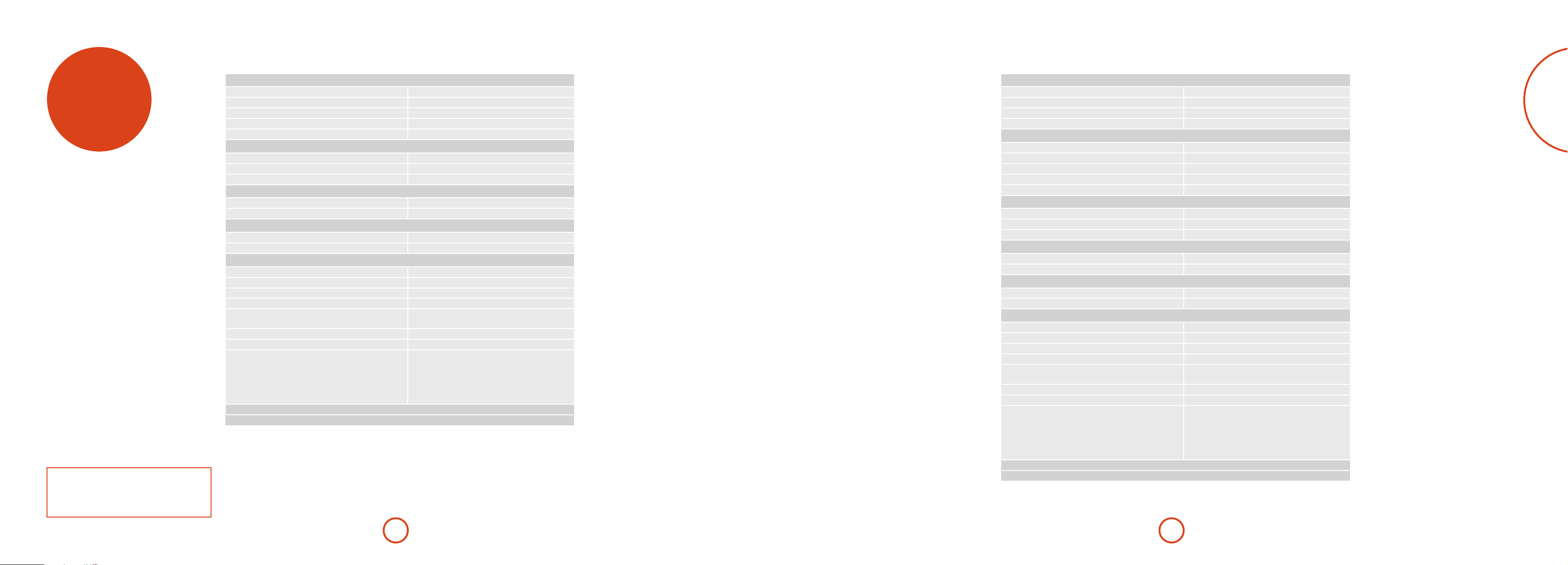
English
AV950
AVR750
specifications
Continual improvement policy
Arcam has a policy of continual improvement for its
products. is means that designs and specications
are subject to change without notice.
Stereo line inputs
Maximum input 4.5V rms
Nominal sensitivity 1V, 2V, 4V (user adjustable)
Input impedance 47kΩ
Signal/noise ratio (A-wtd ref 100W) normal/stereo direct 100dB/120dB
Frequency response 20Hz—20kHz ± 0.1dB
Preamplier outputs
Nominal output level 2V RMS (phono) 4V RMS (XLR)
Output impedance 560Ω
THD+N (20Hz—20kHz) –100dB
Video inputs
Component video signal/noise 85dB
Composite video signal/noise 70dB
Headphone output
Maximum output level into 32Ω 2Vrms
Output impedance <5Ω
General
Mains voltage 110–120V or 220–240V, 50 –60Hz
Power consumption (maximum) 100W (ermal dissipation approx. 340 BTU/hour)
Power consumption (idle, typical) 75W (ermal dissipation approx. 255 BTU/hour)
Power consumption (standby) <0.5W
Dimensions
W x D (including speaker terminals) x H (including feet)
Weight (net) 13.5kg
Weight (packed) 16.8kg
Supplied accessories Mains lead
E&OE
NOTE: All specication values are typical unless otherwise stated.
433 x 425 x 171mm
CR450 remote control
2 x AAA batteries
Manual
DAB/FM aerial
Calibration microphone
Continuous power output, per channel, 8/4
2 channels driven, 20Hz - 20kHz, <0.02% THD 120W/200W
2 channels driven, 1kHz, 0.2% THD 130W/210W
7 channels driven, 1kHz, 0.2% THD 100W/180W
Residual noise & hum (A-wtd) <0.15mV
Stereo line inputs
Maximum input 4.5V rms
Nominal sensitivity 1V, 2V, 4V (user adjustable)
Input impedance 47kΩ
Signal/noise ratio (A-wtd ref 100W) normal/stereo direct 100dB/120dB
Frequency response 20Hz—20kHz ± 0.1dB
Preamplier outputs
Nominal output level 1V RMS
Output impedance 560Ω
THD+N (20Hz—20kHz) –100dB
Video inputs
Component video signal/noise 85dB
Composite video signal/noise 70dB
Headphone output
Maximum output level into 32Ω 2Vrms
Output impedance <5Ω
General
Mains voltage 110–120V or 220–240V, 50 –60Hz
Power consumption (maximum) 1.5kW (ermal dissipation approx. 5200 BTU/hour)
Power consumption (idle, typical) 100W (ermal dissipation approx. 340 BTU/hour)
Power consumption (standby) <0.5W
Dimensions
W x D (including speaker terminals) x H (including feet)
Weight (net) 16.7kg
Weight (packed) 20.0kg
Supplied accessories Mains lead
E&OE
NOTE: All specication values are typical unless otherwise stated.
433 x 425 x 171mm
CR450 remote control
2 x AAA batteries
Manual
DAB/FM aerial
Calibration microphone
E-45E-44
Page 26

English
AVR450
AVR380
Continuous power output, per channel, 8
2 channels driven, 20Hz - 20kHz, <0.02% THD 110W
2 channels driven, 1kHz, 0.2% THD 125W
7 channels driven, 1kHz, 0.2% THD 90W
Residual noise & hum (A-wtd) <0.15mV
Stereo line inputs
Maximum input 4.5V rms
Nominal sensitivity 1V, 2V, 4V (user adjustable)
Input impedance 47kΩ
Signal/noise ratio (A-wtd ref 100W) normal/stereo direct 100dB/110dB
Frequency response 20Hz—20kHz ± 0.2dB
Preamplier outputs
Nominal output level 1V RMS
Output impedance 560Ω
THD+N (20Hz—20kHz) -100dB
Video inputs
Component video signal/noise 85dB
Composite video signal/noise 70dB
Headphone output
Maximum output level into 32Ω 2Vrms
Output impedance <5Ω
General
Mains voltage 110–120V or 220–240V, 50 –60Hz
Power consumption (maximum) 1.5kW (ermal dissipation approx. 5200 BTU/hour)
Power consumption (idle, typical) 100W (ermal dissipation approx. 340 BTU/hour)
Power consumption (standby) <0.5W
Dimensions
W x D (including speaker terminals) x H (including feet)
Weight (net) 15.5kg
Weight (packed) 18.8kg
Supplied accessories Mains lead
E&OE
NOTE: All specication values are typical unless otherwise stated.
433 x 425 x 171mm
CR450 remote control
2 x AAA batteries
Manual
DAB/FM aerial
Calibration microphone
Continuous power output, per channel, 8
2 channels driven, 20Hz - 20kHz, <0.02% THD 90W
2 channels driven, 1kHz, 0.2% THD 115W
7 channels driven, 1kHz, 0.2% THD 75W
Residual noise & hum (A-wtd) <0.15mV
Stereo line inputs
Maximum input 4.5V rms
Nominal sensitivity 1V, 2V, 4V (user adjustable)
Input impedance 47kΩ
Signal/noise ratio (A-wtd ref 95W) normal/stereo direct 100dB/110dB
Frequency response 20Hz—20kHz ± 0.2dB
Preamplier outputs
Nominal output level 1V RMS
Output impedance 560Ω
THD+N (20Hz—20kHz) -100dB
Video inputs
Component video signal/noise 85dB
Composite video signal/noise 70dB
Headphone output
Maximum output level into 32Ω 2Vrms
Output impedance <5Ω
General
Mains voltage 110–120V or 220–240V, 50 –60Hz
Power consumption (maximum) 1.5kW (ermal dissipation approx. 5200 BTU/hour)
Power consumption (idle, typical) 100W (ermal dissipation approx. 340 BTU/hour)
Power consumption (standby) <0.5W
Dimensions
W x D (including speaker terminals) x H (including feet)
Weight (net) 15.1kg
Weight (packed) 18.5kg
Supplied accessories Mains lead
E&OE
NOTE: All specication values are typical unless otherwise stated.
433 x 425 x 171mm
CR450 remote control
2 x AAA batteries
Manual
FM aerial
Calibration microphone
E-47E-46
Page 27

product
guarantee
Worldwide Guarantee
is entitles you to have the unit repaired free of charge, during the rst two years aer
purchase, provided that it was originally purchased from an authorised Arcam dealer.
e Arcam dealer is responsible for all aer-sales service. e manufacturer can take no
responsibility for defects arising from accident, misuse, abuse, wear and tear, neglect or
through unauthorised adjustment and/or repair, neither can they accept responsibility
for damage or loss occurring during transit to or from the person claiming under the
guarantee.
The warranty covers:
Parts and labour costs for two years from the purchase date. Aer two years you must pay
for both parts and labour costs. e warranty does not cover transportation costs at any
time.
Claims under guarantee
is equipment should be packed in the original packing and returned to the dealer from
whom it was purchased. It should be sent carriage prepaid by a reputable carrier – not
by post. No responsibility can be accepted for the unit whilst in transit to the dealer or
distributor and customers are therefore advised to insure the unit against loss or damage
whilst in transit.
For further details contact Arcam at:
Arcam Customer Support Department,
Unit 15, Pembroke Avenue, Waterbeach, CAMBRIDGE, CB25 9QP, England
or via www.arcam.co.uk.
Problems?
If your Arcam dealer is unable to answer any query regarding this or any other Arcam
product please contact Arcam Customer Support at the above address and we will do our
best to help you.
legal
information
On-line registration
You can register your product on-line at www.arcam.co.uk.
“Made for iPod” and “Made for iPhone” mean that an electronic accessory has been designed
to connect specifically to iPod or iPhone, respectively, and has been certified by the developer
to meet Apple performance standards. Apple is not responsible for the operation of this
device or its compliance with safety and regulatory standards. Please note that the use of this
accessory with iPod or iPhone may affect wireless performance.
E-48
Page 28

AV950/AVR750/450/380
MANUEL Amplificateur surround AVR
Français
AVR750
Page 29

sécurité
Consignes de sécurité
importantes
1. Lisez ces instructions.
2. Conservez ces instructions.
3. Respectez toutes les mises en garde.
4. Suivez l’ensemble des instructions.
5. N’utilisez pas cet appareil près d’une source d’eau.
6. Nettoyez uniquement avec un chion sec.
Débranchez l’appareil du circuit électrique avant de prcéder au
nettoyage.
Pour nettoyer les parois de l’appareil, un chion non-pelucheux
et doux devrait sure. N’utilisez pas de produits de nettoyage
chimiques.
Nous déconseillons l’utilisation d’aérosols de nettoyage pour
bois ou de la cire car ceux-ci peuvent laisser des marques
blanches irréversibles.
7. Ne bloquez pas les ouvertures d’aération.
Procédez à l’installation conformément aux du fabricant.
8. N’installez pas l’appareil près de sources de chaleur,
comme des radiateurs, des grilles de chauage, des fours ou
autres appareils (y compris des amplicateurs) produisant
de la chaleur.
9. Ne détournez pas la protection de la prise polarisée ou
de terre.
Une prise polarisée dispose de deux lames, dont l’une plus large
que l’autre. Une prise de terre dispose de deux lames et d’une
troisième broche de mise à la terre. La lame la plus large ou la
troisième broche correspond à un dispositif de protection. Si la
che fournie ne correspond pas à votre installation électrique,
veuillez vous adresser à un électricien pour faire remplacer la
prise obsolète.
ATTENTION : Pour réduire le risque d’électrocution, ne retirez pas le couvercle (ou l’arrière). L’appareil ne contient aucune pièce pouvant
être réparée par l’utilisateur. Confiez toute réparation à du personnel d’entretien qualifié.
MISE EN GARDE: Pour réduire le risque d’incendie ou d’électrocution, protégez cet appareil de la pluie ou de l’humidité.
L’éclair avec une flèche dans un triangle équilatéral permet d’avertir l’utilisateur de la présence de tensions dangereuses non isolées
à l’intérieur de l’appareil, d’une ampleur suffisante pour constituer un risque d’électrocution sur les personnes.
Le point d’exclamation dans un triangle équilatéral permet d’avertir l’utilisateur de la présence de consignes importantes
concernant le fonctionnement et l’entretien (réparations) dans la documentation livrée avec l’appareil.
ATTENTION : Au Canada et aux Etats-Unis, pour éviter tout risque d’électrocution, faites correspondre la lame la plus large
de la fiche à la fente la plus large de la prise et insérez la fiche entièrement dans la prise.
10. Installez le câble électrique de telle sorte qu’il ne puisse
pas être piétiné ou écrasé, notamment au niveau des ches,
des prises et des points de sortie de l’appareil.
11. Utilisez uniquement des câbles/accessoires conformes
aux recommandations du fabricant.
12. Utilisez uniquement un meuble à roulettes, un support,
un trépied, des xations ou une table
recommandé(e) par le fabricant ou
livré(e) avec l’appareil.
En cas d’utilisation d’un meuble à
roulettes, déplacez le meuble/appareil
avec précaution pour éviter de le renverser,
ce qui pourrait entraîner des blessures.
13. Débranchez l’appareil en cas d’orage ou lorsque vous ne
l’utiliserez pas sur une période prolongée.
14. Conez les réparations à un technicien qualié.
Il est nécessaire de faire réparer l’appareil s’il a été endommagé
d’une manière ou d’une autre, par exemple si le l électrique ou
la prise est abimé(e), si du liquide a été renversé ou des objets
ont pénétré dans l’appareil, si l’appareil a été exposé à la pluie
ou à l’humidité, s’il ne fonctionne pas normalement, ou s’il est
tombé.
15. Pénétration d’objet ou de liquide
MISE EN GARDE – Veillez à ce qu’aucun objet ou liquide ne
puisse pénétrer à l’intérieur de l’appareil par les ouvertures
d’aération. Cet appareil doit être protégé des gouttes ou des
éclaboussures. Il ne faut pas poser d’objet rempli de liquide, tel
qu’un vase, sur l’appareil.
16. Consignes de réparation
ATTENTION - Ces consignes de réparation sont destinées
à technicien qualié uniquement. Pour limiter le risque
d’électrocution, n’eectuez aucune procédure de réparation
autre que celles précisées dans le mode d’emploi, si vous n’êtes
pas qualié pour le faire.
17. Climat
Cet appareil est conçu pour une utilisation en climat tempéré et
dans un cadre domestique. Débranchez l’appareil en cas d’orage
pour éviter qu’il ne soit endommagé par une surtension.
18. Sources d’alimentation
Branchez cet appareil uniquement sur une source
d’alimentation du type décrit dans le mode d’emploi ou comme
indiqué sur l’appareil.
La principale méthode d’isolation de l’appareil du circuit
électrique consiste à débrancher la prise. Il faut installer
l’appareil de manière à pouvoir le débrancher facilement.
19. Protection du câble électrique
Les câbles électriques doivent être acheminés de manière à ce
qu’ils ne puissent pas être piétinés ou écrasés par des éléments
placés sur eux ou contre eux. Veillez particulièrement à leur
point de sortie de l’appareil.
20. Lignes électriques
Eloignez les antennes externes des lignes électriques.
21. Raccordement des enceintes
Toute enceinte doit être branchée sur l’AVR750/450/380 à l’aide
d’un câble de classe II (sans connexion à la terre). Le nonrespect de cette consigne peut endommager l’appareil.
22. Périodes de non-utilisation
Si l’appareil possède une fonction de mise en veille, un courant
faible continuera de circuler lorsqu’il sera réglé sur ce mode.
Débranchez le cordon secteur de la prise murale si l’appareil
doit rester inutilisé pendant une période prolongée.
Produit de classe II
Cet équipement est une Classe II ou un
appareil électrique à double isolation. Il a été
conçu de telle manière à ce qu’il ne nécessite
pas de branchement de sécurité à une prise
de terre.
23. Odeur inhabituelle
En cas d’odeur inhabituelle provenant de l’appareil, éteignez
immédiatement l’appareil et débranchez-le du circuit électrique.
Contactez votre revendeur et ne rebranchez pas l’appareil.
PRÉCAUTIONS D’INSTALLATION
Pour que la chaleur puisse se dissiper correctement,
n’installez pas l’appareil dans un espace conné, tel qu’une
bibliothèque ou un meuble similaire.
• Il est conseillé de laisser plus de 0,3 m (12 pouces).
• Ne posez pas d’autres appareils sur celui-ci.
z
zz
z
Mur
Wall
INFORMATIONS FCC POUR LES CLIENTS AUX
ÉTATSUNIS
1. PRODUIT
Cet appareil est conforme à la Section 15 des règles de la
FCC. Son fonctionnement est soumis aux deux conditions
suivantes: (1) Cet appareil ne doit pas provoquer
d’interférences nuisibles, et (2) cet appareil doit accepter
toute interférence reçue, y compris des interférences
pouvant provoquer un fonctionnement indésirable.
2. CONSIGNE IMPORTANTE:
NE MODIFIEZ PAS CE PRODUIT
Ce produit, s’il est installé conformément aux consignes
de ce manuel, est conforme aux normes de la FCC. Toute
modication sans obtention de l’accord express d’ARCAM
peut entrainer une annulation de votre autorité, accordée
par la FCC, à utiliser le produit.
3. REMARQUE
Ce produit a fait l’objet de tests et a été jugé conforme
aux limitations d’un appareil numérique de classe B,
conformément à la Section 15 des règles de la FCC. Ces
limites sont imposées pour assurer une protection susante
contre les interférences produites dans une installation
résidentielle.
CONSIGNES DE SÉCURITÉ
POUR LES CLIENTS EN EUROPE
• Évitez les températures élevées. Laissez un espace
susant pour que la chaleur puisse se dissiper si
l’appareil est posé sur une étagère.
• Maniez le câble d’alimentation avec soin. Prenez la che
en main lorsque vous débranchez le câble.
• Protégez l’appareil de l’humidité, de l’eau et de la
poussière.
• Débranchez le câble d’alimentation lorsque vous
n’utilisez pas l’appareil pour une période prolongée.
• Ne bloquez pas les ouvertures d’aération.
• Veuillez à ce qu’aucun objet ne pénètre dans l’appareil.
• Protégez l’appareil de tout contact avec des insecticides,
du benzène et des diluants.
• Ne démontez pas et ne modiez l’appareil en aucune
façon.
Cet appareil génère, utilise et peut émettre de l’énergie
de fréquence radio et, s’il n’est pas installé et utilisé
conformément aux instructions, peut produire des
interférences nuisibles aux communications radio. Il n’est
cependant pas garanti qu’aucune interférence ne se produira
dans une installation particulière. Si cet appareil provoque
des interférences nuisibles aectant la réception de
programmes radio ou télévisés, ce qui peut être déterminé
en éteignant puis rallumant l’appareil, l’utilisateur peut
tenter de remédier à ces interférences en adoptant une ou
plusieurs des mesures suivantes:
• Réorientez ou déplacez l’antenne de réception.
• Augmentez la distance entre l’appareil et le récepteur.
• Branchez l’appareil sur une prise située sur un circuit
diérent de celui sur lequel est branché le récepteur.
• Si vous avez besoin d’aide, veuillez vous adresser à
un revendeur agréé pour la distribution de ce type de
produit ou un technicien radio/télévision qualié.
• Il ne faut pas empêcher l’aération en couvrant les
ouvertures d’aération d’articles tels que des journaux,
une nappe ou des rideaux.
• Il ne faut pas poser de source de ammes vives, une
bougie allumée par exemple, sur l’appareil.
• Respectez les réglementations locales concernant la
mise au rebus des piles.
• Protégez l’appareil des gouttes ou des éclaboussures.
• Ne posez pas d’objets remplis de liquide, un vase par
exemple, sur l’appareil.
• Ne touchez pas le câble électrique si vos mains sont
mouillées.
• Lorsque le sélecteur est sur OFF, l’appareil n’est pas
complètement débranché du CIRCUIT ÉLECTRIQUE.
• L’appareil doit être installé près de l’alimentation
électrique pour que celle-ci soit facile d’accès.
Français
REMARQUE SU R LE RECYCLA GE:
Les matériaux d’emballage de ce produit sont recyclables et peuvent être réutilisés. Veuillez jeter tous les matériaux conformément
aux règlementations de recyclage de votre municipalité. Lorsque vous jetez l’appareil, veuillez respecter les règles ou
règlementations locales.
Il ne faut jamais mettre les piles à la poubelle ou au feu, mais s’en débarrasser conformément aux règlementations locales
concernant la mise au rebus des piles.
Cet appareil ainsi que les accessoires fournis, à l’exception des piles, représente un appareil auquel s’applique la directive DEEE.
MISE AU REBUS ADÉQUATE DE CET APPAREIL
Les plaques signalétiques indiquent que cet appareil ne doit pas
être jeté avec le reste des déchets ménagers, et ce dans toute l’Union
Européenne.
Pour protéger l’environnement et la santé en évitant une mise au
rebus des déchets non contrôlée et pour conserver les ressources de
matériaux, cet appareil doit être recyclé de manière responsable.
Si vous devez jeter votre appareil, veuillez le faire conformément
aux systèmes de renvoi et de collecte locaux, ou contactez le revendeur ayant vendu cet appareil.
F-3F-2
Page 30

Table des matières
sécurité ......................................................F-2
Bienvenue ................................................. F-5
avant de commencer… .......................... F-6
connecteurs du panneau arrière .......... F-9
connexions audio/vidéo ......................F-10
Guide de connexion ......................................................F-12
connecteurs radio .................................F-13
autres connecteurs ...............................F-14
enceintes .................................................F-15
fonction nement ....................................F-17
fonction nement du panneau avant ..F-19
télécommande .......................................F-20
configuration essentielle .....................F-26
configuration automatique des
enceintes .................................................F-27
menus de configuration .......................F-28
Modes de décodage .............................F-33
Dolby volume...................................................................F-35
fonction nement du tuner ....................F-36
fonction nement réseau/USB...............F-37
Configuration multi pièces ..................F-38
Guide de raccordement multi pièces ......................F-39
person nalisation de la CR450 .............F-40
Dépannage .............................................F-42
spécifications .........................................F-44
garantie du produit ..............................F-47
mentions légales ...................................F-47
Nous vous remercions d’avoir acheté ce récepteur FMJ d’Arcam.
Depuis plus de trente ans, Arcam fabrique des appareils audio spécialisés d’une qualité
remarquable. Les nouveaux récepteurs AV950/AVR750/450/380 font partie de cette longue
lignée de produits hi d’exception. La gamme FMJ capitalise sur l’expérience considérable
d’Arcam, l’un des plus grands spécialistes britanniques de produits audio, conçus pour vous
assurer des années de plaisir audiophile sans le moindre problème.
Ce manuel vous permettra de trouver des indications détaillées sur la façon d’utiliser
votre récepteur AV950/AVR750/450/380. Le début de ce manuel vous propose des conseils
d’installation, avant de décrire l’utilisation du produit puis de donner des informations
supplémentaires sur les fonctionnalités plus perfectionnées. Reportez-vous à la table des matières
ci-contre pour rechercher les rubriques qui vous intéressent.
Nous espérons que votre récepteur FMJ vous assurera des années de fonctionnement sans
le moindre problème. Dans l’éventualité, peu probable, où une panne surviendrait, ou si
vous recherchez simplement des informations supplémentaires sur les produits Arcam, les
représentants de notre réseau de revendeurs se feront un plaisir de vous aider. D’autres
informations sont disponibles sur notre site web d’Arcam à l’adresse www.arcam.co.uk.
L’équipe de développement FMJ
Bienvenue
Français
Une installation professionnelle ?
Il est possible que l’installation de votre AV950/AVR750/450/380 ait été faite par un revendeur Arcam agréé dans le cadre
de votre installation hi. Dans ce cas, vous n’aurez pas à consulter les rubriques de ce manuel concernant l’installation et la
conguration, et vous pourrez passer directement aux rubriques concernant l’utilisation de l’appareil. Veuillez consulter la table
des matières pour aller à ces rubriques.
Une installation par vos soins ?
L’AV950/AVR750/450/380 est un instrument audiovisuel puissant et sophistiqué. Si vous congurez l’appareil par vous-même,
il est conseillé de lire la totalité de ce guide avant de commencer. La conguration et l’emplacement des enceintes, par exemple,
sont des éléments clé pour pouvoir proter au mieux de votre AV950/AVR750/450/380 et pour garantir une harmonie des
éléments de votre système.
F-5F-4
Page 31

avant de
commencer…
L’AV950, AVR380, l’AVR450 et l’AVR750 sont des processeurs
home cinéma de haute qualité, aux performances poussées,
conçus selon les normes de conception et de fabrication
strictes d’Arcam. Ils associent un traitement numérique et des
composantes audio et vidéo de haute performance pour que
vous puissiez bénécier d’un centre multimédia d’une qualité
inégalée.
L’AV950/AVR750/450/380 permet de commander et de basculer
entre sept sources analogiques et six sources audionumériques,
en plus de la radio interne FM (et pour les modèles AV950,
AVR450 et AVR750, la radio DAB), et des sources audio en
réseau et USB, et représente ainsi un centre idéal pour les
systèmes de home cinéma comme pour les systèmes stéréo à
deux voies.
La plupart de ces composants source pouvant également
générer des signaux vidéo, l’AV950/AVR750/450/380 comprend
AVR750
également des prises de transmission de qualité pour les
signaux vidéo HDMI, composite et composante. Vous pouvez
commander l’AV950/AVR750/450/380 à partir des boutons de
la façade, de la télécommande ou du port RS232.
La télécommande CR450 livrée avec l’AV950/AVR750/450/380
est une télécommande d’apprentissage «universelle» pour
douze appareils, simple d’utilisation et pouvant commander,
une fois congurée, l’ensemble d’un système. Une importante
bibliothèque de codes internes permet de la programmer pour
que vous puissiez commander des lecteurs CD et BD, des
lecteurs DVD, des téléviseurs et autres périphériques.
L’installation de l’AV950/AVR750/450/380 dans une pièce
d’écoute constitue un processus important qui demande une
attention particulière à chaque étape. C’est pour cela que les
consignes d’installation sont très détaillées et doivent être
suivies si vous souhaitez obtenir des performances de haut
niveau.
Les récepteurs AV950/AVR750/450/380 sont conçus
pour produire un niveau de performance permettant
véritablement de donner vie à la musique et aux lms.
Mise en place de l’appareil
< Posez l’appareil sur une surface plane et ferme, en évitant
de l’exposer directement aux rayons du soleil ou à une
source de chaleur ou d’humidité.
< Ne posez pas l’AV950/AVR750/450/380 au-dessus d’un
amplicateur de puissance ou de toute autre source de
chaleur.
< Ne mettez pas l’amplicateur dans un espace fermé tel
qu’une bibliothèque ou une armoire à moins qu’elle
ne soit pourvue d’une bonne ventilation. L’AV950/
AVR750/450/380 chaue lorsqu’il est en marche.
< Ne mettez aucun composant ou élément au-dessus de
l’amplicateur car il peut obstruer le ux d’air autour du
dissipateur thermique, provoquant l’échauement de
l’amplicateur. (L’unité placée au-dessus de l’amplicateur
deviendrait elle aussi bouillante.)
< Veillez à ce qu’il n’y ait pas d’obstacle devant le capteur
infrarouge de la façade, car cela gênerait le fonctionnement
de la télécommande. Si une ligne de mire directe est
impossible, il est possible d’utiliser un répétiteur pour
télécommande sur le connecteur au dos de l’appareil (voir
pageF-14).
< Ne posez pas votre platine-disque sur cet appareil. Les
platines sont des appareils très sensibles aux bruits générés
par l’alimentation secteur. Ces derniers peuvent s’entendre
en bruit de fond si la platine est trop proche de l’appareil.
Alimentation
L’amplicateur est livré avec une prise de courant moulée
intégrée au câble. Vériez que la prise livrée correspond bien à
votre circuit électrique. Vériez que la prise livrée correspond
bien à votre circuit électrique. S’il vous faut un autre câble
d’alimentation, veuillez vous adresser à votre revendeur Arcam.
Si la tension ou les prises de votre circuit électrique sont
diérentes, contactez immédiatement votre revendeur Arcam.
L’AV950/AVR750/450 peut être positionné sur une tension
de 220-240 V (position de sélecteur 230 V) ou sur 110-120 V
(position de sélecteur 115 V).
REMARQUE
Veillez à ce que l’AV950/AVR750/450 soit éteint et le câble
électrique débranché avant de modier la position du
commutateur de voltage.
Insérez la prise IEC du câble d’alimentation dans la prise à
l’arrière de l’amplicateur, en veillant à la pousser fermement.
Branchez l’autre extrémité du câble sur votre prise secteur, et, si
nécessaire, allumez celle-ci.
Vous pouvez allumer l’AV950/AVR750/450/380 à partir du
bouton MARCHE/ARRÊT situé sur la façade de l’appareil.
Lorsqu’il est allumé, le voyant lumineux de la façade est vert.
Mode veille
Vous pouvez mettre l’AV950/AVR750/450/380 sur veille à partir
de la touche P de la télécommande CR450. En mode veille,
le voyant lumineux de la façade est rouge et la consommation
d’énergie est inférieure à 0,5 watt.
En mode veille, il est possible qu’un bourdonnement résiduel
provenant du transformateur électrique à l’intérieur de
l’amplicateur soit audible. Ceci est tout à fait normal. Toutefois,
si l’appareil ne doit pas être utilisé pendant longtemps,
nous conseillons de le débrancher du circuit électrique an
d’économiser de l’énergie.
Câbles de branchement
Il est recommandé d’utiliser des câbles blindés de haute qualité,
conçus pour ce genre d’application. L’utilisation d’autres câbles,
dont les caractéristiques d’impédance dièrent, risque d’aecter
les performances de votre système. (Par exemple, n’utilisez
pas de câble conçu pour un usage vidéo pour le transport
des signaux audio). Les câbles doivent être aussi courts que
possible.
Lors de la connexion du matériel, il convient de vérier que
les câbles d’alimentation secteur sont positionnés le plus loin
possible de vos câbles audio. Vous éviterez ainsi les bruits
indésirables dans les signaux audio.
Pour en savoir plus sur le câblage des enceintes, veuillez
consulter la rubrique «Enceintes» à partir de la page F-15.
Interférences radio
L’AV950/AVR750/450/380 est un appareil audio qui contient
des microprocesseurs et autres dispositifs électroniques
numériques. La conception de chacun des modèles est
conforme aux normes de compatibilité électromagnétique les
plus strictes.
C’est un produit de classe A. Dans un environnement
domestique, cet appareil peut provoquer des interférences
radio, auxquelles l’utilisateur pourra remédier en prenant les
mesures nécessaires.
Si l’AV950/AVR750/450/380 provoque des interférences sur
la réception radio ou télévision (ce qui peut être déterminé en
éteignant et en rallumant l’AV950/AVR750/450/380), il faut
prendre les mesures suivantes:
< Réorienter l’antenne ou placer le câble du récepteur aecté
le plus loin possible de l’AV950/AVR750/450/380 et de ses
câbles.
< Changer l’emplacement du récepteur par rapport à l’AV950/
AVR750/450/380.
< Brancher le périphérique aecté et l’AV950/
AVR750/450/380 sur des prises de courant diérentes.
Si le problème persiste, veuillez contacter votre revendeur
Arcam.
Français
F-7F-6
Page 32

Marques déposées
~ 50 – 60 Hz
100W MAX
1.2A MAX TRIG Z2 Z2 IR
TRIG Z1
RS232
DC6V
Z1 IR
OUTPUT1 OUTPUT2AV
AV
ETHERNET
USB 5V / 1A
115 230
FM/DAB
PVR
PVR
VCRBDSAT
AV BD
Y
Pb
Pr
SAT
STBZ2 OUT
Z2
VIDEO OUT
GAME PVR
STB BD
PVRS AT
BDAV
BDCDCD
GAME
STB
STB
GAME
OPTICAL
COAXIAL
ARC
COMPOSITE
DIGITAL AUDIO
ANALOGUE AUDIO
HDMI
COMPONENT
Arcam est une marque déposée appartenant à A & R
Cambridge Ltd.
Dolby Volume
Fabriqué sous licence des laboratoires Dolby.
Dolby et le symbole du double D sont des
marques déposées des laboratoires Dolby.
Dolby True HD, Digital, Digital Plus,
PL IIx
Fabriqué sous licence des laboratoires Dolby.
Dolby, Pro Logic et le symbole du double D sont
des marques déposées des laboratoires Dolby.
DTS-HD Master Audio™
Fabriqué sous licence sous brevet américain n°:
5,956,674; 5,974,380; 6,226,616; 6,487,535;
7,212,872; 7,333,929; 7,392,195; 7,272,567
et autres brevets américains et internationaux
validés ou en cours de validation.
DTS-HD, son Symbole, et DTS-HD et son
Symbole sont des marques déposées, et le logo
DTS-HD Master Audio sont des marques
déposées de DTS, Inc. Le produit comprend le
logiciel.
© DTS, Inc. Tous droits réservés.
DTS-HD High Resolution Audio™
Fabriqué sous licence sous brevet américain n°:
5,956,674; 5,974,380; 6,226,616; 6,487,535;
7,212,872; 7,333,929 et autres brevets américains
et internationaux validés et en cours de
validation.
DTS-HD, son Symbole, et DTS-HD et son
Symbole sont des marques déposées, et le logo
DTS-HD High Resolution Audio sont des
marques déposées de DTS, Inc. Le produit
comprend le logiciel.
© DTS, Inc. Tous droits réservés.
DTS Digital Surround
ES|Neo:6|96/24™
Fabriqué sous licence sous brevet américain n°:
5,956,674; 5,974,380; 6,226,616; 6,487,535;
7,003,467; 7,212,872 et autres brevets américains
et internationaux validés et en cours de
validation.
DTS, son Symbole, et DTS et son Symbole sont
des marques déposées, et le logo DTS Digital
Surround | ES | Neo:6 | 96/24 sont des marques
déposées de DTS, Inc. Le produit comprend le
logiciel.
© DTS, Inc. Tous droits réservés.
REMARQUE
Veuillez consulter les rubriques «Position de l’appareil»,
«Mise en marche» et «Câbles d’interconnexion»
AAC/AAC Plus
aacPlus est une marque déposée de Coding
Technologies. Pour en savoir plus, voir
www.codingtechnologies.com.
FLAC
FLAC Decoder Copyright © 2000, 2001, 2002,
2003, 2004, 2005, 2006, 2007, 2008 Josh Coalson.
La redistribution et l’utilisation sous des
formes de code source et binaire, avec ou sans
modification, sont permises sous les conditions
suivantes:
- La redistribution du code source doit contenir
la mention sur le droit d’auteur ci-dessus,
cette liste de conditions et la limitation de
responsabilité ci-dessous.
- La redistribution sous forme binaire doit
reproduire la mention sur le droit d’auteur
ci-dessus, cette liste de conditions et la
limitation de responsabilité ci-dessous dans la
documentation et/ou d’autres matériaux livrés
avec la distribution.
- Ni le nom de Xiph.org Foundation, ni les noms
de ses collaborateurs ne peuvent être utilisés
à des fins d’approbation ou de promotion de
produits dérivés de ce logiciel sans l’obtention
d’un accord préalable par écrit.
CE LOGICIEL EST FOURNI PAR LES
PROPRIÉTAIRES DU COPYRIGHT ET
SES COLLABORATEURS «TEL QUEL»
ET TOUTES GARANTIES EXPRESSES
OU IMPLICITES, Y COMPRIS, MAIS
SANS S’Y LIMITER, LES GARANTIES
IMPLICITES DE QUALITÉ MARCHANDE
ET DE CONVENANCE À L’EMPLOI
SONT REJETÉES. EN AUCUN CAS LA
FONDATION OU SES COLLABORATEURS
NE SAURONT ÊTRE TENUS RESPONSABLES
DE TOUT DOMMAGE DIRECT, INDIRECT,
CIRCONSTANCIEL, PARTICULIER,
EXEMPLAIRE OU CONSÉCUTIF (Y
COMPRIS, MAIS SANS S’Y LIMITER, LA
FOURNITURE DE BIENS OU DE SERVICES
DE RECHANGE, LA PERTE D’UTILISATION,
DE DONNÉES OU DE BÉNÉFICES, OU
TOUTE INTERRUPTION COMMERCIALE),
QUELLE QUE SOIT LA CAUSE ET LA
THÉORIE SUR LA RESPONSABILITÉ, QUE CE
SOIT UNE RESPONSABILITÉ DE CONTRAT,
STRICTE OU A TORT (Y COMPRIS DE LA
NÉGLIGENCE OU AUTRE) DÉCOULANT
DE QUELLE QUE MANIÈRE QUE CE SOIT
DE L’UTILISATION DE CE LOGICIEL, MÊME
EN CAS D’AVIS DE LA POSSIBILITÉ DE TEL
DOMMAGE.
vTuner
MP3
iPod
Ce produit est protégé par certains droits de
propriété intellectuelle appartenant à NEMS et
BridgeCo. L’utilisation ou la distribution de cette
technologie en dehors de ce produit est interdite
sans licence de NEMS et BridgeCo ou d’une
filiale agréée.
La technologie de décodage audio MPEG Layer-3
est sous licence de Fraunhofer IIS et Thomson
multimedia.
iPod est une marque déposée d’Apple Inc.
enregistrée aux États-Unis et dans d’autres pays.
HDMI, le logo HDMI logo et High-Definition
Multimedia Interface sont des marques déposées
de HDMI Licensing LLC.
connecteurs
du panneau
arrière
AVR750
AVR450
AVR380
Connecteurs audio
Analogiques à deux canaux,
voir pageF-11.
Sortie du
pré-amplificateur
voir pageF-11.
AV950
Sortie du
pré-amplificateur
voir pageF-11.
Connecteurs HDMI
Pour en savoir plus, voir pageF-10.
STB
GAME
STBZ2 OUT
GAME
ANALOGUE AUDIO
PREAMP OUT
CFL SL SBL
SBRSUBSRFR
PREAMP OUT
FLFR
SUB
SR SL
SBR
ZONE 2 R ZONE 2 L
C
SBR SR FR C
SBL
HDMI
Connecteurs numériques
Connecteurs audio numériques
coaxiaux et optiques, voir pageF-11.
PVR
VCRBDSAT
BDAV
PVR
ZONE 2 R
SBR SR FR C FL SL SBL
CLASS 2 WIRING
SBR
ZONE 2 R ZONE 2 L
PVRSAT
ETHERNET
BDCDCD
COAXIAL
DIGITAL AUDIO
SR FR C FL SL SBL
AV
STB
OPTICAL
SPEAKER OUTPUTS
8Ω LOAD IMPEDANCE RECOMMENDED
Connecteurs pour enceintes
Pour en savoir plus, voir pageF-16.
BALANCED OUTPUTS
SUB
FL SL SBL
OUTPUT1 OUTPUT2AV
USB 5V / 1A
Connecteurs vidéo
AVR750
AVR450
AV950
FM/DAB
Prise d’antenne FM, ou
prise d’antenne DAB (sur les
modèles AV950, AVR450 et
AVR750 uniquement).
ARC
Z2
GAME PVR
VIDEO OUT
FM/DAB
AV BD
115 230
ZONE 2 L
STB BD
COMPOSITE
Connecteurs coaxiaux vidéo
composite et composante
(Y, Pb, Pr), voir pageF-11.
Connexion de la Zone2,
voir pageF-38.
Y
Pb
Pr
SAT
COMPONENT
~ 50 – 60 Hz
1.5KW MAX
RS232
DC6V
1.2A MAX TRIG Z2 Z2 IR
Entrée d’alimentation
Branchez le câble d’alimentation
secteur qui convient ici.
Sélection de la tension
Vériez que la tension sélectionnée
correspond à votre installation
électrique. L’AVR380 ne nécessite pas
AVR380
de sélecteur de tension: la tension
s’adapte aux exigences locales.
page F-7 avant de procéder au raccordement de votre
amplicateur intégré AV950/AVR750/450/380 !
TRIG Z1
Z1 IR
Antennes,
commande et communication
Connecteurs réseau, USB, antenne
FM/DAB, sortie tension, commande série,
de déclenchement et infrarouge, voir
pageF-13, F-14.
Français
F-9F-8
Page 33

connexions
Y
1.2A MAX TRIG Z2 Z2 IR
TRIG Z1
RS232
DC6V
Z1 IR
1.2A MAX TRIG Z2 Z2 IR
TRIG Z1
RS232
DC6V
Z1 IR
AV BD
Y
Pb
Pr
SAT
COMPONENT
1.2A MAX TRIG Z2 Z2 IR
TRIG Z1
RS232
DC6V
Z1 IR
OUTPUT1 OUTPUT2AV
ETHERNET
USB 5V / 1A
FM/DAB
PVR
VCRBDSAT
AV BD
Y
Pb
Pr
SAT
Z2
VIDEO OUT
GAME PVR
STB BD
ARC
COMPOSITE
COMPONENT
1.2A MAX TRIG Z2 Z2 IR
TRIG Z1
RS232
DC6V
Z1 IR
OUTPUT1 OUTPUT2AV
AV
ETHERNET
USB 5V / 1A
FM/DAB
PVR
PVR
VCRBDSAT
AV BD
Y
Pb
Pr
SAT
STB
Z2
VIDEO OUT
GAME PVR
STB BD
PVRSAT
BDAV
BDCDCD
GAME
STB
STB
GAME
OPTICAL
ARC
ANALOGUE AUDIO
HDMI
1.2A MAX TRIG Z2 Z2 IR
TRIG Z1
RS232
DC6V
Z1 IR
AV BD
Y
Pb
Pr
SAT
GAME PVR
STB BD
COMPOSITE
COMPONENT
~ 50 – 60 Hz
1.5KW MAX
1.2A MAX TRIG Z2 Z2 IR
TRIG Z1
RS232
DC6V
Z1 IR
OUTPUT1 OUTPUT2AV
AV
ETHERNET
USB 5V / 1A
115 230
FM/DAB
PVR
PVR
VCRBDSAT
AV BD
Y
Pb
Pr
SAT
SBR SR FR C FL SL SBL
SBR
ZONE 2 R ZONE 2 L
SR FR C FL SL SBL
STBZ2 OUT
Z2
VIDEO OUT
GAME PVR
STB BD
ZONE 2 R
CLASS 2 WIRING
ZONE 2 L
8Ω LOAD IMPEDANCE RECOMMENDED
PVRSAT
BDAV
BDCDCD
GAME
STB
STB
GAME
SPEAKER OUTPUTS
OPTICAL
COAXIAL
ARC
COMPOSITE
DIGITAL AUDIO
ANALOGUE AUDIO
HDMI
COMPONENT
1.2A MAX TRIG Z2 Z2 IR
TRIG Z1
RS232
DC6V
Z1 IR
OUTPUT1 OUTPUT2AV
AV
ETHERNET
USB 5V / 1A
FM/DAB
PVR
VCRBDSAT
AV BD
Y
Pb
Pr
SAT
Z2
VIDEO OUT
GAME PVR
STB BD
PVRSAT
BDCDCD
STB
GAME
OPTICAL
COAXIAL
ARC
audio/vidéo
Avant de raccorder votre AV950/AVR750/450/380 aux
composants source et enceintes, veuillez lire attentivement les
pages suivantes qui indiquent toutes les connexions d’entrée et
de sortie possibles. La rubrique «Enceintes» explique comment
brancher vos enceintes sans endommager l’amplicateur et
comment disposer vos enceintes pour obtenir des performances
optimales.
Généralités
Le nom des entrées est indiqué pour que vous puissiez voir
facilement à quels périphériques elles correspondent (par ex.
«BD» ou «VCR»). Elles ont toutes le même circuit d’entrée. Par
conséquent, rien ne vous empêche de brancher un périphérique
diérent sur chacune des entrées. Par exemple, si vous avez
deux lecteurs BD et que l’entrée AV n’est pas utilisée, vous
pouvez brancher le second lecteur BD sur l’entrée AV.
Lorsque vous branchez une source vidéo, son audio doit être
raccordée aux prises qui conviennent. Par exemple, si vous avez
un décodeur satellite branché sur une entrée vidéo SAT, l’audio
doit être branchée sur les entrées audio S AT !
En règle générale, les connexions HDMI orent une meilleure
qualité qu’une connexion composite, bien que pour que toute
source vidéo soit disponible en Zone2, il faut une connexion
composite entre l’AV950/AVR750/450/380 et la source.
Procédures de connexions
< Autant que possible, branchez les sorties analogiques et
numériques des sources numériques. Cela permet d’utiliser
une entrée numérique pour la zone principale et l’entrée
analogique correspondante pour la sortie de la Zone2.
< Veillez à acheminer les câbles le plus loin possible des
câbles d’alimentation électrique pour limiter le risque de
bourdonnement et autres bruits nuisibles.
STB
GAME
HDMI
VCRBDSAT
Connecteurs HDMI
STB, GAME, AV, SAT, BD, VCR, PVR
Branchez les sorties vidéo HDMI de votre appareil source sur
les entrées HDMI correspondantes.
SORTIE
Branchez cette sortie sur l’entrée vidéo HDMI de votre écran.
Cette sortie est compatible avec le canal de retour audio (ARC)
HDMI 1.4. Si votre téléviseur prend cette fonction en charge, le
son provenant du tuner interne du téléviseur (par ex. Freeview,
Freesat, DVB-T) sera disponible à partir de l’entrée «Display»
de l’AV950/AVR750/450/380.
OUTPUT1 OUTPUT2AV
PVR
ARC
Connecteurs vidéo composante
Ces entrées conviennent au raccordement de périphériques
source transmettant des signaux de vidéo analogique
composante (YUV ou YPbPr) ou RG B de haute qualité. Ces
signaux sont en général disponibles à partir de lecteurs BD, de
décodeurs ou de consoles de jeux.
Remarques importantes sur les entrées
vidéo composante
< Lorsque vous branchez vos appareils sur ces
connecteurs, veillez à respecter les codes lettres/
couleurs de chaque entrée. Ne pas le faire n’abimera
pas l’appareil mais pourra entrainer des images
Sorties préamplificateur
analogique
PREAMP OUT
CFL SL SBL
Entrée AUX en façade
instables ou des mauvaises couleurs.
Y
Pb
Pr
SAT
AV BD
COMPONENT
ENTRÉE VIDÉO COMPOSANTE AV, SAT, BD
Branchez les sorties vidéo composante de votre appareil source
sur ces entrées.
Connecteurs composite
GAME PVR
STB BD
COMPOSITE
< Les entrées vidéo composante ont une bande passante
susante pour les signaux vidéo NTSC (525/60) ou
PAL (625/50) vidéo et HDTV.
Connecteurs de la Zone 2
Z2 OUT
Le connecteur audio analogique de la sortie Z2 peut servir à
raccorder la sortie audio stéréo de l’AV950/AVR750/450/380 à
un amplicateur situé dans une seconde pièce.
Branchez la sortie vidéo analogique sur l’écran de la Zone2.
Veuillez consulter «Conguration multi pièces» pageF-38
pour en savoir plus.
Z2
VIDEO OUT
Toutes les sorties préamplicateur analogiques sont
tamponnées, possèdent une faible impédance de sortie, sont de
niveau ligne et sont alignées sur le réglage du volume de la Zone
1. Elles peuvent piloter de longs câbles ou plusieurs entrées en
parallèle si nécessaire.
Pour en savoir plus sur le raccordement des enceintes ou
d’autres amplicateurs de puissance, voir voir pageF-15 et
F-16.
Entrées audio analogiques
STB
GAME
SBRSUBSRFR
HDMI
BDAV
ANALOGUE AUDIO
L’entrée AUX en façade avant peut servir d’entrée analogique ou
numérique optique.
Pour les sources analogiques, utilisez un câble stéréo 3,5 mm.
Pour les sources numériques, utilisez un câble optique 3,5 mm.
L’entrée en façade peut également servir d’entrée du micro de
conguration automatique.
Prise ECOUTEURS en façade
Français
Cette prise accepte les écouteurs d’une impédance entre
32Ω et 600Ω, équipés d’une prise jack stéréo 3,5 mm. La
prise écouteurs reste active sauf lorsque le son de l’AV950/
AVR750/450/380 est coupé.
Lorsque la prise écouteurs est utilisée, les sorties des enceintes
et les sorties préamplicateur analogique sont automatiquement
PVR
coupées.
GAME, PVR, STB, BD
Branchez ces entrées sur les sorties composite de votre appareil
source disponible.
Connecteurs audionumériques
PVRSAT
STB, GAME, AV, BD, PVR, CD
Branchez les entrées gauche et droite sur les sorties gauche et
droite de votre appareil source.
REMARQUE :
Pour chaque entrée, vous devez eectuer les réglages
«Source vidéo» et «Source audio» conformes au type de
connexion.
(voir «Cong. d’entrée» pageF-29)
BD
COAXIAL
CD
DIGITAL AUDIO
AV
STB
OPTICAL
SAT, PVR, BD, CD, STB, AV
Branchez ces entrées sur les sorties numériques de votre
appareil source disponible.
F-11F-10
Page 34

Guide de connexion
1.2A MAX TRIG Z2 Z2 IR
TRIG Z1
RS232
DC6V
Z1 IR
AV BD
Y
Pb
Pr
SAT
Z2
VIDEO OUT
GAME PVR
STB BD
ARC
COMPOSITE
COMPONENT
Adressez-vous à votre revendeur Arcam ou à un spécialiste des
installations d’antenne pour en savoir plus sur les conditions de
réception locales.
Lecteur Blu-ray Disc (DB)/DVD
Ce schéma indique comment procéder aux connexions audio et
vidéo sur un lecteur BD/DVD classique.
Les préférences de raccordement vidéo sont, dans l’ordre:
< utilisez le connecteur HDMI (si la sortie HDMI est
proposée par le lecteur), sinon branchez les trois
connecteurs vidéo composante.
< utilisez la connexion composite si les sorties HDMI ou
composante ne sont pas proposées par votre lecteur.
Dans chaque cas, utilisez les entrées vidéo marquées BD sur
l’AV950/AVR750/450/380.
Le mode de connexion de prédilection correspond à l’utilisation
du connecteur numérique coaxial (en général marqué
DIGITAL AUDIO OUT), en plus des sorties analogiques coaxiales
pour les canaux gauche et droit.
Dans chaque cas, utilisez les entrées audio marquées BD sur
l’AV950/AVR750/450/380.
Récepteur satellite
Le raccordement d’un récepteur satellite est identique à celui
d’un lecteur, et l’ordre de préférence est le même en fonction des
sorties proposées sur le récepteur satellite.
Dans chaque cas, utilisez les entrées marquées SAT sur l’AV950/
AVR750/450/380. Veuillez noter que l’entrée audio numérique à
partir d’un récepteur satellite peut parfois nécessiter l’utilisation
d’un câble d’interconnexion coaxial/TOSLINK (connecteur
numérique), car certains récepteurs satellite ne passent pas bien
ou pas du tout l’audio sur HDMI.
Lecteur CD
Branchez la sortie audio numérique (si proposée par le lecteur
CD) sur l’entrée numérique CD de l’AV950/AVR750/450/380, à
l’aide d’un câble d’interconnexion coaxial de qualité.
Branchez les sorties audio analogiques gauche et droite
du lecteur CD sur les entrées analogiques CD de l’AV950/
AVR750/450/380, à l’aide de câbles d’interconnexion coaxiaux
de qualité.
connecteurs
radio
STB
GAME
STBZ2 OUT
PREAMP OUT
GAME
CFL SL SBL
HDMI
BDAV
ANALOGUE AUDIO
SBRSUBSRFR
VCRBDSAT
PVR
ZONE 2 R
SBR SR FR C FL SL SBL
CLASS 2 WIRING
SBR
ZONE 2 R ZONE 2 L
PVRSAT
BDCDCD
STB
DIGITAL AUDIO
SPEAKER OUTPUTS
8Ω LOAD IMPEDANCE RECOMMENDED
OPTICAL
COAXIAL
SR FR C FL SL SBL
OUTPUT1 OUTPUT2AV
PVR
ETHERNET
AV
USB 5V / 1A
ARC
ZONE 2 L
FM/DAB
Z2
VIDEO OUT
GAME PVR
STB BD
COMPOSITE
SAT
AV BD
COMPONENT
Y
Pb
DC6V
Pr
1.2A MAX TRIG Z2 Z2 IR
TRIG Z1
RS232
Z1 IR
Connecteurs d’antenne
L’AV950/AVR750/450 est équipé d’un module de réception
AM/FM et d’un récepteur DAB. L’AVR380 est équipé d’un
module de réception FM module. Le type d’antenne dont
vous avez besoin dépend de vos préférences d’écoute et des
conditions locales.
Votre AV950/AVR750/450/380 est en mesure d’orir une
~ 50 – 60 Hz
1.5KW MAX
115 230
réception radio exceptionnelle, mais celle-ci dépend de la
qualité du signal de transmission.
Testez les antennes livrées avec votre appareil. Si vous vous
trouvez dans une région au signal moyen à fort, celles-ci
devraient sure à une bonne réception. Dans les régions où le
signal est faible, il vous faudra peut-être une antenne sur le toit
ou de grenier.
BD/SAT
Pr Pb Y
DAB/FM
(DAB n’est pas disponible sur l’AVR380)
FM/DAB
USB 5V / 1A
utilisez des punaises ou du ruban adhésif pour
Une fois l’installation terminée et le DAB/FM
reçu, vériez la force du signal en appuyant sur la touche
INFO de la façade ou de la télécommande jusqu’à ce que
l’indice de qualité du signal s’ache.
Lorsque la qualité du signal est faible, il est conseillé
d’utiliser une antenne à gain élevé, montée en extérieur ou
sur le toit pour recevoir le plus grand nombre possible de
services.
Dans les zones de transmission de bande III (au RoyaumeUni par exemple), utilisez une antenne Yagi à éléments
multiples montés à la verticale, car les transmissions sont
polarisées à la verticale. Si vous êtes proche de plus d’un
transmetteur, utilisez une antenne omnidirectionnelle ou
AVR450
AVR750
AV950
Dans des régions où le signal est puissant,
l’antenne laire DAB/FM «T» fournie peut
servir. Montez l’antenne le plus haut possible
sur un mur.
Au Royaume-Uni, les éléments «T» doivent
être placés à la verticale pour la réception
DAB car les transmissions sont polarisées
à la verticale. Dans d’autres régions,
veuillez consulter votre revendeur Arcam
ou tester les positions horizontales et
verticales pour obtenir une meilleure
réception.
Testez tous les murs de la pièce pour voir
quel mur donne la meilleure réception et
maintenir l’antenne en forme de «T». Sachez
toutefois qu’aucune punaise ne doit rentrer en
contact avec le l interne de l’antenne.
Français
dipôle pliée.
Si les services DAB de votre région sont transmis sur bande
REMARQUE :
Pour chaque entrée, vous devez eectuer les réglages
«Source audio» conformes au type de connexion. (voir
«Cong. d’entrée» pageF-29)
L, veuillez consulter votre revendeur pour savoir quelle
antenne utiliser.
F-13F-12
Page 35

TRIG Z1
Z1 IR
1.2A MAX TRIG Z2 Z2 IR
TRIG Z1
RS232
DC6V
Z1 IR
OUTPUT1 OUTPUT2AV
FM/DAB
PVR
AV BD
Y
Pb
Pr
SAT
Z2
VIDEO OUT
GAME PVR
STB BD
ARC
COMPOSITE
COMPONENT
Z2 IR
Z1 IR
REMARQUE
TRIG Z2 Z2 IR
TRIG Z1
RS232
Z1 IR
Les prises indiquées «Z2» correspondent aux connexions
utilisées dans une installation multi pièces. Pour en savoir
plus sur ces connecteurs, voir pageF-38.
autres
enceintes
connecteurs
Connecteur de série
Connecteur de série RS232
RS232
Connecteur USB
L’AV950/AVR750/450/380 peut lire des chiers stockés sur
un périphérique de stockage de masse USB, une clé USB
en général, ou tout appareil USB de type «périphérique de
stockage de masse» compatible.
L’AV950/AVR750/450/380 n’accepte qu’une connexion
directe des périphériques USB et ne prend pas en charge les
périphériques branchés sur un hub. S’il vous faut accéder
À utiliser avec des périphériques de commande disposant d’un
port de série RS232 (contrôleurs tactiles AMX et Crestron par
exemple).
Connecteur réseau
Le réseau est un vaste sujet et ce manuel ne donne que des
consignes brèves. Pour en savoir plus sur l’introduction de
l’AV950/AVR750/450/380 sur votre réseau informatique,
veuillez vous adresser à votre revendeur Arcam ou à un
spécialiste.
régulièrement à la prise USB il peut être utile d’utiliser une
rallonge USB; voir pageF-37 pour connaître les types de
chiers pris en charge.
Connecteurs de déclenchement
TRIG Z1
TRIG Z2
pointe: Sortie de
déclenchement
prise: Terre
Pour en savoir sur l’utilisation des fonctions réseau de l’AV950/
AVR750/450/380, de la prise USB et pour avoir la liste des types
de chiers pris en charge, voir pageF-37.
ETHERNET
USB 5V / 1A
Les connecteurs de déclenchement (TRIG Z1 et TRIG Z2)
fournissent un signal électrique à chaque mise en marche de
l’AV950/AVR750/450/380 et à chaque fois que la zone adéquate
est activée.
Ethernet
Si un câble Ethernet est branché, l’AV950/AVR750/450/380
tente automatiquement de se connecter à votre réseau.
Vous devez utiliser un câble CAT5 branché sur la prise RJ45
indiquée ETHERNET au dos de l’appareil.
Si votre réseau utilise une adresse IP statique plutôt que le
DHCP, il faudra donner l’adresse IP, le portail d’accès à Internet
et le DNS; voir pageF-32 pour savoir comment congurer le
réseau.
Le signal de déclenchement permet d’activer et de désactiver
des éléments compatibles d’un système home cinéma. Vous
pouvez par exemple régler un déclenchement pour allumer
votre téléviseur et un lecteur BD à chaque mise en marche de
l’AV950/AVR750/450/380.
L’AV950/AVR750/450/380 comprend deux prises de sortie
de déclenchement, capables de transmettre un signal de
basculement de 12 V, 70 mA. La prise est conçue pour
des prises jacks mono 3,5 mm: la pointe est la sortie de
déclenchement, la prise est de terre.
TRIG Z1
À utiliser pour allumer et éteindre à distance des amplis ou des
appareils source de la Zone 1. On = 12 V, O = 0 V.
TRIG Z2
Utiliser pour allumer et éteindre à distance des amplis ou des
appareils source de la Zone2. On = 12 V, O = 0 V.
Connecteurs infrarouge (IR)
Z1 IR
Z2 IR
Les entrées infrarouge (Z1 IR et Z2 IR) permettent de brancher
des récepteurs IR externes, soit lorsque le récepteur infrarouge
de la façade de l’AV950/AVR750/450/380 est entièrement
ou partiellement obstrué ou pour pouvoir utiliser une
télécommande en Zone2.
L’AV950/AVR750/450/380 comprend deux entrées infrarouges,
chacune conçue pour des prises jack stéréo ou mono 3,5 mm.
La pointe est le signal modulé, la gaine est la terre.
Z1 IR
Cette entrée permet d’utiliser un récepteur IR local lorsque la
façade de l’AV950/AVR750/450/380 est bloquée.
Z2 IR
Cette entrée permet d’utiliser un récepteur infrarouge sur la
Zone2 pour pouvoir commander l’AV950/AVR750/450/380 à
partir d’une autre pièce.
pointe: Signal modulé
prise: Terre
Parmi les fournisseurs de récepteurs infrarouges et de système
et d’accessoires d’émission, vous avez Xantech. Allez sur le site
www.xantech.com pour en savoir plus, ou demandez conseil à
votre revendeur Arcam.
REMARQUE
Les entrées infrarouges de l’AV950/AVR750/450/380
sont conçues pour des signaux modulés. Si le récepteur
infrarouge externe démodule le signal infrarouge, il ne
fonctionnera pas. L’AV950/AVR750/450/380 ne permet pas
non plus d’alimenter des récepteurs externes sur la prise
infrarouge, il est donc nécessaire de fournir une source
d’alimentation externe.
Sortie 6 V
DC6V
1.2A MAX
Ceci permet d’obtenir une connexion d’alimentation de 6 V
pour les produits Arcam rSeries.
L’AVR750/450/380 vous permet de brancher jusqu’à sept
enceintes et un subwoofer actif sur le système principal. Les
canaux de sortie correspondent aux enceintes installées à
l’avant gauche, au centre, à l’avant à droite, en surround droite,
en surround arrière gauche, en surround arrière droite et un
subwoofer actif.
La conguration et le placement de vos enceintes sont très
importants. Toutes les enceintes, à l’exception du subwoofer,
doivent être placées autour de votre position de visionnage/
d’écoute normale. Le subwoofer doit être placé dans une
position qui donne une fréquence en réponse égale, quelle que
soit la position d’écoute. Un placement incorrect entrainera un
boom des basses sur certaines zones. Pour trouver la position
idéale de votre subwoofer, il est souvent nécessaire d’eectuer
une série de tests. Il est en général préférable de commencer
près d’un mur mais à au moins 1 mètre de tout coin. Vous
pouvez également consulter le manuel de votre subwoofer pour
obtenir des conseils de placement.
L’enceinte centrale permet une restitution
plus réaliste des dialogues. L’enceinte
centrale doit avoir une balance tonale
similaire à celle des enceintes avant
gauche et droite et doit être placée à la
Centre
même hauteur.
Subwoofer
Un subwoofer améliore énormément les performances des basses
de votre système. Ceci est utile pour restituer des eets spéciaux de
cinéma, notamment lorsqu’un canal LFE (Low Frequency Eects)
spécial est disponible, comme sur de nombreux disques proposant les
technologies Dolby ou DTS.
Sur de grandes installations, il peut être nécessaire de disposer de
plusieurs subwoofers, notamment dans des pièces dont la charpente
est en bois. Il faut prêter une attention particulière à l’emplacement de
plusieurs subwoofers car il peut y avoir des eets d’annulation entre les
éléments. Il vous faudra peut-être demander conseil à un spécialiste.
Surround arrière gauche et droit
Les enceintes surround arrière gauche et droite
permettent d’ajouter de la profondeur et d’améliorer
la localisation du son, et doivent être placées
à environ un mètre au-dessus des oreilles de
l’auditeur. Placez les deux enceintes arrière surround
de manière à former un arc de cercle d’environ
150degrés entre chaque enceinte surround arrière
et l’enceinte centrale. Les enceintes surround arrière
doivent faire face à l’avant de la pièce, comme illustré
sur le schéma pour obtenir une «zone d’écoute»
plus importante.
F-15F-14
Français
Avant gauche et droite
Placez vos enceintes avant gauche et droite de manière
à obtenir une bonne image stéréo pour une restitution
musicale normale comme pour les modes multicanal.
Si vous les placez trop près l’une de l’autre, la manque
d’espace se fera ressentir. Si elles sont trop éloignées
l’une de l’autre, une image stéréo semblera créer un
grand «trou» au milieu et sera coupée en deux. S’il
n’y a pas d’autre solution que de placer les enceintes
à distance l’une de l’autre, cet eet peut être réglé par
la restitution musicale en utilisant l’extraction sonore
centrale à partir des enceintes gauche et droite (voir le
mode Dolby Pro Logic II Music).
Surround gauche et droite
Les enceintes surround gauche et droite
restituent les sons ambiants et les eets
présents dans un système home cinéma
multicanal et doivent être installées un peu
au-dessus des oreilles de l’auditeur.
Page 36

Raccordement des enceintes
~ 50 – 60 Hz
1.5KW MAX
1.2A MAX TRIG Z2 Z2 IR
TRIG Z1
RS232
DC6V
Z1 IR
OUTPUT1 OUTPUT2AV
AV
ETHERNET
USB 5V / 1A
115 230
FM/DAB
PVR
PVR
VCRBDSAT
AV BD
Y
Pb
Pr
SAT
Z2
VIDEO OUT
GAME PVR
STB BD
PVRSAT
BDCDCD
STB
OPTICAL
COAXIAL
ARC
COMPOSITE
DIGITAL AUDIO
COMPONENT
~ 50 – 60 Hz
1.5KW MAX
1.2A MAX TRIG Z2 Z2 IR
TRIG Z1
RS232
DC6V
Z1 IR
OUTPUT1 OUTPUT2AV
AV
ETHERNET
USB 5V / 1A
115 230
FM/DAB
PVR
PVR
VCRBDSAT
AV BD
Y
Pb
Pr
SAT
SBR SR FR C FL SL SBL
SBR
ZONE 2 R ZONE 2 L
SR FR C FL SL SBL
STBZ2 OUT
Z2
VIDEO OUT
GAME PVR
STB BD
ZONE 2 R
CLASS 2 WIRING
ZONE 2 L
8Ω LOAD IMPEDANCE RECOMMENDED
PVRSAT
BDAV
BDCDCD
GAME
STB
STB
GAME
SPEAKER OUTPUTS
OPTICAL
COAXIAL
ARC
COMPOSITE
DIGITAL AUDIO
ANALOGUE AUDIO
HDMI
COMPONENT
Pour brancher les enceintes, dévissez les bornes
correspondantes au dos de l’AVR750/450/380, introduisez les
ls d’enceinte par les ouvertures de chaque poste, et revissez
les bornes. Veillez à ce que la borne rouge (positive/+) de
l’enceinte soit branchée sur la borne rouge (positive/+) au dos
de l’appareil, et la borne noire (négative/–) de l’enceinte sur la
borne noire (négative/–) au dos de l’appareil.
SPEAKER OUTPUTS
ZONE 2 R
SBR SR FR C FL SL SBL
CLASS 2 WIRING
SBR
ZONE 2 R ZONE 2 L
Il est important de ne pas laisser de ls à nu toucher un autre
câble ou le boîtier de l’appareil. Cela pourrait provoquer un
court-circuit et endommager votre AVR750/450/380.
Ne resserrez pas trop les bornes des enceintes, et n’utilisez pas
de pinces, etc., car cela pourrait endommager les bornes, et
annulerait la garantie du produit.
Câbles d’enceintes
Les enceintes doivent être raccordées à l’amplicateur à l’aide
de câbles de cuivre de qualité, haute pureté et faible impédance.
Il faut éviter les câbles d’enceinte bon marché: ils représentent
une mauvaise économie et peuvent réduire énormément la
qualité du son.
Les câbles vers les enceintes doivent être aussi courts que
possible. Les raccordements aux bornes d’enceintes doivent
toujours être bien resserrés, que ce soit avec des ls à nu ou des
connecteurs à fourche.
8Ω LOAD IMPEDANCE RECOMMENDED
SR FR C FL SL SBL
ZONE 2 L
Link MUST
Le lien
DOIT être
be removed
supprimé
Bi-amplification des enceintes avant gauche et droite
La bi-amplication correspond à l’utilisation de deux canaux d’amplication par enceinte.
Cela permet d’obtenir une meilleure qualité de son qu’avec un câblage simple classique. Si
vous n’avez pas d’enceintes surround arrière (si vous avez un système surround 5.1 plutôt
que 7.1), vous pouvez utiliser les sorties d’enceinte surround arrière pour bi-amplier
les enceintes avant gauche et droite, si vos enceintes sont compatibles avec la fonction
de bi-amplication. Les canaux non-utilisés peuvent également servir à alimenter des
enceintes stéréo dans une autre pièce (Zone2).
Les enceintes qui acceptent la bi-amplication disposent de deux séries de bornes +/- par
enceinte, en général reliées entre elles par des barres métalliques. Ces barres métalliques
DOIVENT être retirées avec une bi-amplication, sous peine d’entrainer des dommages sur
l’amplicateur qui ne seront pas couverts par la garantie.
Pour bi-amplier les enceintes avant gauche et droite, retirez les barres métalliques des
bornes des enceintes. Branchez le subwoofer ou les bornes LF sur les bornes FL et FR de
l’AVR750/450/380. Branchez le tweeter ou les bornes HF sur les bornes SBL et SBR de
l’AVR750/450/380. Pour nir, parcourez les types d’enceintes sur le menu de conguration
et réglez l’option «Utiliser les canaux 6+7» sur «BiAmp G+D»; voir pageF-26.
SBL
SBR
FL
FR
Connexion de subwoofers
PREAMP OUT
CFL SL SBL
Link MUST
Le lien
DOIT être
be removed
supprimé
Utilisation d’amplificateurs de puissance
externes
Il est possible de compléter l’amplicateur de puissance
interne de l’AV950/AVR750/450/380 ou de le remplacer par
une amplication de puissance externe. Branchez les prises
PREAMP OUT sur les entrées de votre amplicateur:
PREAMP OUT
CFL SL SBL
SBRSUBSRFR
FL, FR, C
Branchez celles-ci sur les canaux avant équivalents (droite,
gauche et centre) de votre ampli.
SUB
Sortie subwoofer. Branchez celle-ci sur l’entrée de votre
subwoofer actif, le cas échéant.
SR, SL
Sorties surround droite et surround gauche. Branchez celles-ci
sur les entrées surround droite et gauche de l’ampli.
SBR, SBL
Sorties surround arrière droite et surround arrière gauche
(utilisées uniquement avec des systèmes 7.1). Branchez celles-ci
sur les entrées surround arrière droite et surround arrière
gauche de l’ampli.
Toutes les sorties analogiques pré-amplicateur sont
temporisées, ont une faible impédance de sortie et sont au
niveau ligne. Elles peuvent piloter de longs câbles ou plusieurs
entrées en parallèle si nécessaire.
fonction-
nement
Fonctionnement de votre AV950/
AVR750/450/380
Pour l’achage des informations, nous conseillons d’utiliser
dans la mesure du possible l’OSD (Achage à l’écran) sur votre
écran.
Mise en marche
Appuyez sur le bouton marche/arrêt de la façade. Le voyant
lumineux devient vert, l’écran de la façade de l’appareil ache
le message «ARCAM». Une fois l’initialisation terminée, l’écran
indique le réglage du volume et le nom de l’entrée sélectionnée.
Veuillez patienter jusqu’à ce que l’initialisation de l’appareil
soit terminée avant de commencer à utiliser l’AV950/
AVR750/450/380. Il est conseillé de patienter au moins 10
secondes après avoir éteint l’appareil avant de le remettre en
marche.
Veille
L’AV950/AVR750/450/380 dispose d’un mode de veille que
l’on peut activer en appuyant sur la touche STANDBY de la
télécommande. En mode veille, l’écran devient noir et le voyant
lumineux de MARCHE/ARRÊT LED est rouge.
Toutefois, si l’appareil ne doit pas être utilisé pendant
longtemps, nous conseillons de le débrancher du circuit
électrique an d’économiser de l’énergie.
Pour rallumer l’appareil à partir du mode
veille
Appuyez sur la touche VEILLE de la télécommande ou sur l’une
des touches de la façade (autre que la touche marche/arrêt).
Écran de la façade
L’AV950/AVR750/450/380 est prêt à l’emploi au bout de quatre
secondes.
BD 37
Sélection d’une source
Pour sélectionner une source précise, utilisez la touche –INPUT
ou INPUT+ jusqu’à ce que la source s’ache sur l’écran de la
façade, ou (si disponible) appuyez sur la touche correspondant à
la source que vous recherchez sur la télécommande. Les sources
suivantes sont disponibles:
STB
GAME
AV
SAT
BD
VCR
PVR
CD
FM
DAB
NET
USB
AUX
DISPLAY
La plupart des entrées audio disposent de connexions à la
fois analogiques et numériques. Vous devez préciser le type
de connexion utilisée pour chaque entrée à partir de l’option
«Source audio» dans le menu «Conguration d’entrée», voir
pageF-29. Veuillez noter qu’un mauvais réglage peut entrainer
Entrée du décodeur
Entrée de la console de jeu
Entrée audiovisuelle
Entrée de récepteur satellite
Entrée de lecteur de disque Blu-Ray
Entrée de magnétoscope
Entrée de magnétoscope numérique
Entrée de lecteur compact disque
Entrée de tuner interne
Entrée de tuner interne (ces sources
dépendent du marché et ne sont peut-être
pas disponibles sur votre AVR750/450)
Entrée Ethernet
Entrée USB externe à semi-conducteurs
(par ex. clé USB, iPad)
Entrée auxiliaire (façade)
Le canal de retour audio (ARC) d’un écran
HDMI 1.4. À utiliser avec un téléviseur
HDMI 1.4 avec tuners TV internes.
Stéréo directe
Pour écouter une entrée stéréo analogique pure, appuyez
sur la touche DIRECT. Le mode de stéréo directe contourne
automatiquement tous les traitements et toute fonction
surround. En mode direct, le traitement numérique est coupé
pour améliorer la qualité du son et réduire le bruit numérique
de l’AV950/AVR750/450/380 à un minimum absolu.
Remarque: lorsque le mode de stéréo directe est sélectionné,
aucune sortie numérique n’est disponible et aucune gestion des
basses n’est eectuée, ce qui signie que les signaux des basses
ne seront pas redirigés vers un subwoofer.
Réglage du volume
Il est important de comprendre que le niveau de l’indice de
volume n’est pas un indice exact de la puissance envoyée sur vos
enceintes. L’AV950/AVR750/450/380 envoie souvent la totalité
de sa puissance de sortie avant que le contrôle du volume
n’atteigne sa position maximum, notamment si l’on écoute de
la musique enregistrée lourdement. En comparaison, certaines
bandes son de lm peuvent sembler très calmes, car beaucoup
de réalisateurs préfèrent réserver les niveaux maximum aux
séquences d’eets spéciaux.
Écouteurs
Pour utiliser des écouteurs sur l’AV950/AVR750/450/380,
branchez les écouteurs sur la prise PHONES au centre de la
façade.
Lorsque des écouteurs sont branchés sur la prise PHONES de
la façade, les sorties de la Zone 1 sont coupées et l’audio est
sous-mixée sur les deux canaux (2.0). Le sous-mixage à deux
canaux est requis pour que le canal du centre et les informations
surround soient audibles sur les écouteurs.
Français
une absence de son. Cette option est réglée par défaut sur Audio
HDMI. Si vous n’utilisez pas d’audio HDMI, ce réglage doit être
La fenêtre d’achage indique la source sélectionnée et le
dernier réglage d’achage des informations sélectionné
(cette ligne d’informations peut être changée à partir de la
toucheINFO).
Le réglage du volume actuel de la Zone 1 (37,0 dB dans
l’exemple ci-dessus) s’ache sur la façade. Le réglage du volume
de la Zone2 s’ache temporairement à chaque fois qu’il est
modié.
SBRSUBSRFR
L’AV950/AVR750/450/380 permet également de brancher un subwoofer actif sur la sortie
SUB. Veuillez consulter le manuel du subwoofer pour connaître la bonne installation et le
bon raccordement du subwoofer.
modié.
Le mode de traitement et les fonctions de Stéréo directe sont
mis en mémoire et rappelés pour chaque entrée.
F-17F-16
Page 37

Utilisation de la Zone 2
Grâce à la Zone2, les occupants d’une chambre, d’une véranda,
d’une cuisine, etc. peuvent écouter ou voir une source diérente
sur un volume diérent de la zone principale (Zone 1).
La sélection de la source et le contrôle du volume de la Zone2
sont obtenus:
< en utilisant soit un récepteur infrarouge sur la Zone2 (voir
«Connexions de contrôle de la Zone2» pageF-38), ou
< en passant au contrôle de la Zone2 grâce à la touche de
zone sur la façade, ou
< en appuyant sur AMP + OK sur la télécommande.
L’écran VFD de la façade indique que le contrôle est passé à la
Zone2.
STANDBY Z2 50
Pour mettre la Zone2 en marche, appuyez sur la touche Zone
(ou AMP + OK) puis sur la touche veille de la télécommande.
Utilisez les touches de sélection de source pour sélectionner une
source autre que celle de la Zone 1.
FOLLOW Z1 Z2 50
Menu supplémentaire de la
façade
Appuyez sur la touche MENU et maintenez-la enfoncée plus de
quatre secondes pour accéder au menu supplémentaire, pour
pouvoir procéder aux opérations suivantes:
Rétablir les paramètres d’usine
Cette option vous permet de rétablir tous les paramètres par
défaut de votre AV950/AVR750/450/380 tels qu’ils étaient
sélectionnés à la sortie d’usine.
Changer le code de la télécommande
Par défaut, l’AV950/AVR750/450/380 répond au code système
RC5 16. Si nécessaire, par exemple si un autre appareil sur votre
système utilise également ce code système RC5, vous pouvez le
passer à 19.
Restaurer la sauvegarde de protection
Cette option vous permet de restaurer tous les réglages tels
qu’ils ont été sauvegardés à partir de la fonction «Enregistrer la
sauvegarde de protection». Cette option est utile si les réglages
sont modiés involontairement. Il permet également de
retrouver l’état sauvegardé de l’appareil avant une mise à niveau
de logiciel.
Mise à niveau du logiciel par USB
Le logiciel de votre AV950/AVR750/450/380 peut être mis à
niveau à l’aide d’une clé USB contenant un chier de mise à
niveau du logiciel.
Vous pouvez télécharger la dernière version du logiciel, ainsi
que les instructions de mise à niveau, sur le site Internet
d’Arc a m ( www.arcam.co.uk/advice-and-support.htm).
fonction-
nement du
panneau
avant
Sélectionne la stéréo ou les modes surround
disponibles pour la source actuelle.
Sélectionne les informations achées sur la
partie inférieure gauche du panneau avant.
OK
Permet d’accéder aux options sélectionnées
sur le menu de conguration. Maintenez
cette touche enfoncée pour rétablir la
résolution la plus basse sur les sorties vidéo
(HDMI: 480p).
Info
Mode
Direct
Marche/arrêt de la stéréo directe. Propose un chemin
analogique direct entre les entrées analogiques et les
sorties avant gauche et droite. Permet d’éteindre tous les
modes de traitement surround et de refermer les circuits
DSP pour obtenir une qualité de son stéréo optimale.
Écran
Cette option permet de choisir
la luminosité de l’écran:
extérieure/sombre/brillante.
Zone
Permet de sélectionner
le contrôle de la Zone 1
et de la Zone2.
Muet
Permet de couper toutes les
sorties audio analogiques
dans la zone sélectionnée.
Voyant lumineux Marche/Veille
Ce voyant indique le statut du récepteur
et est de couleur verte lorsque l’AV950/
AVR750/450/380 est en marche. Il est rouge
lorsque l’AV950/AVR750/450/380 est en mode
veille.
Français
Veuillez noter que le contrôle de la Zone2 à partir de la Zone
1 revient automatiquement au contrôle de la Zone 1 au bout de
quelques secondes d’inactivité.
La Zone2 peut également être contrôlée à l’aide d’une
télécommande programmable ou d’un système d’automatisation
domestique. Veuillez vous adresser à votre revendeur ou à votre
installateur pour obtenir de plus amples informations.
Enregistrer la sauvegarde de protection
Cette option vous permet de sauvegarder tous les réglages de
l’AV950/AVR750/450/380 sur une zone protégée de la mémoire.
Ces réglages peuvent être récupérés à partir de l’option
Restaurer ci-dessus.
– Saisie du code PIN
Entrez le code PIN de la sauvegarde de protection à l’aide des
touches ', ,, < et > de la télécommande (n’utilisez pas
les touches chiffrées). Le code PIN par défaut est 1234.
– Changer le code PIN
Permet de choisir un code PIN diérent du code par défaut.
Entrez le code PIN de la sauvegarde de protection actuel à
l’aide des touches ', ,, < et > de la télécommande
((n’utilisez pas les touches chiffrées). Le code PIN par défaut
est 1234. Une fois le code PIN actuel correctement saisi,
entrez un nouveau code PIN comme on vous le demande, et
une nouvelle fois pour le confirmer.
– QUITTER
Annulation et retour au menu supplémentaire.
Entrée
Ces touches permettent de sélectionner
la source connectée à l’entrée
correspondante (ou entrée interne).
Il est possible d’empêcher la sélection
des sources qui ne sont pas utilisées sur
le menu de conguration.
AVR750
Permet de sélectionner les
menus de conguration sur
l’achage à l’écran (OSD).
Menu
Aux
Niveau d’entrée de
ligne auxiliaire à
usages multiples,
entrée de microphone
de calibrage et entrée
optique numérique de
3,5 mm (SPDIF).
Volume
Permet de régler le volume
de sortie analogique
de la zone sélectionnée
(sortie ligne, enceintes et
écouteurs).
Alimentation
Permet de mettre l’AV950/
AVR750/450/380 sur ou hors
tension.
Une fois l’appareil éteint, il faut
patienter au moins dix secondes
avant de le rallumer.
Casque
Cette prise accepte
les écouteurs d’une
impédance entre 32Ω et
600Ω, équipés d’une prise
jack stéréo 3,5 mm.
Récepteur de télécommande. Il est placé derrière la fenêtre
d’achage, au-dessus de la touche MENU de la façade.
Veillez à ce qu’il n’y ait pas d’obstacle entre le récepteur et la
télécommande. Si ce n’est pas possible, utilisez un capteur
diérent relié à l’entrée Z1 IR au dos de l’appareil.
F-19F-18
Page 38

télécom-
1
2
3
4
5
6
7
8
9
0
OK
RTN
VOL+
VOL-
FAV+ FAV-
INFO
MENU
DIRECT
EFFECT
BASS
TREB
TRIM
SYNC
DISP MODE
DISC MENU POP UP
SUBT
AUDIO
AMP
SUB
EQ
RPT
abc def
ghi jkl mno
pqrs tuv
wxyz
mande
Le contrôleur de la
télécommande universelle CR450
La CR450 est une télécommande «universelle»
particulièrement sophistiquée capable de contrôler jusqu’à huit
appareils. Elle est pré-programmée pour pouvoir être utilisée
sur l’AV950/AVR750/450/380 et d’autres produits Arcam
(tuners FM/DAB, lecteurs CD et lecteurs DVD).
Grâce à sa bibliothèque importante de codes intégrée, elle peut
également servir à contrôler d’autres composants audiovisuels:
téléviseurs, décodeurs et décodeurs satellite, magnétoscopes,
lecteurs CD, etc. Veuillez consulter la liste des codes donnée au
dos de ce manuel, à partir de la page 49.
La commande CR450 est une commande «d’apprentissage».
Vous pouvez lui apprendre presque toutes les fonctions d’une
ancienne télécommande pour un seul appareil.
Utilisation de la télécommande
Veuillez garder à l’esprit les règles suivantes lorsque vous
utilisez la télécommande.
< Veillez à ce qu’aucun obstacle ne se trouve entre la
télécommande et le capteur de la télécommande
sur l’AV950/AVR750/450/380. La portée de la
télécommande est d’environ 7 mètres. Si le capteur
de la télécommande est obstrué, vous pouvez utiliser
la prise d’entrée de la télécommande Z1 IR au dos de
l’appareil. Veuillez vous adresser à votre revendeur
pour obtenir de plus amples informations.)
< La télécommande peut devenir capricieuse si
le capteur de la télécommande sur l’AV950/
AVR750/450/380 est exposé à une puissante
luminosité solaire ou articielle.
< Remplacez les piles si vous remarquez une réduction
de la portée de la télécommande.
EQ
2
1
abc def
5
4
ghi jkl mno
7
pqrs tuv
DISP MODE
FAV+ FAV-
SYNC
DISC MENU POP UP
INFO
8
0
EFFECT
TRIM
3
6
9
wxyz
RPT
DIRECT
SUB
MENU
OK
RTN
AUDIO
BASS
SUBT
TREB
STB
AUX
AV
SAT
CR450
AMP
VOL+
VOL-
USBTUN NET
VCRBD
GAME
CDPVR
Insertion des piles dans la
télécommande
1. Ouvrez le compartiment des piles situé au dos de la
télécommande en faisant glisser son couvercle.
2. Insérez deux piles AAA dans le compartiment comme
illustré.
3. Vous pouvez maintenant faire glisser fermement
le couvercle jusqu’à ce que vous entendiez un clic
indiquant que le couvercle est verrouillé.
Remarques sur les piles :
< Une mauvaise utilisation des piles peut entrainer un risque
de fuite ou d’explosion.
< Ne mélangez pas piles usagées et piles neuves.
< Ne mélangez pas des piles de types diérents – elles
peuvent paraître identiques, mais des piles diérentes
peuvent avoir une tension diérente.
< Veillez à ce que les bornes positive (+) et négative(-)
de chaque pile correspondent aux indications du
compartiment des piles.
< Sortez les piles de l’appareil si vous n’avez pas l’intention de
l’utiliser pendant plus d’un mois.
< Lorsque vous devez jeter des piles usagées, veuillez
respecter les consignes gouvernementales ou locales en
vigueur dans votre pays ou votre région.
Informations utiles
Rétroéclairage
Un rétroéclairage éclaire la télécommande pendant huit
secondes à chaque pression sur une touche. Ceci est utile si
vous utilisez la télécommande dans une pièce sombre.
Si le voyant marche/arrêt clignote
Une lumière intermittente rapide indique la pression d’une
touche valide.
Si le voyant clignote rapidement plusieurs fois, cela indique
l’acheminement d’informations (un code d’appareil, par
exemple), ou le démarrage et la n d’une séquence de
programmation.
Sur ce manuel, le symbole ‘*’ indique un clignotement de
voyant.
Délais expirés et touches non attribuées
Temps d’expiration: au bout de 20 secondes, la CR450 quitte le
mode de programmation et revient au mode de fonctionnement
normal.
Temps d’expiration pour touche coincée: si une touche reste
enfoncée pendant 30 secondes, la CR450 cesse de transmettre
des informations par infrarouge pour préserver les piles. La
CR450 reste désactivée jusqu’à ce que l’ensemble des touches
soient relâchées.
Touches non attribuées: la CR450 ignore toute touche non
attribuée pour un mode périphérique précis et ne transmet pas
d’infrarouge.
Indicateur de piles faibles
Lorsque les piles faiblissent, le voyant clignote cinq fois à
chaque pression sur une touche:
* * * * *
Dans ce cas, veuillez installer dès que possible deux piles
alcalines AAA neuves.
Mode périphérique/Touches
source
La CR450 étant capable de commander votre AV950/
AVR750/450/380 ainsi que d’autres appareils, une bonne
partie des touches auront plus d’une fonction, selon le «mode
périphérique» sélectionné sur la télécommande.
Les touches de mode périphérique (illustrées ci-dessous)
permettent de sélectionner la source sur l’AV950/
AVR750/450/380. Si vous appuyez brièvement sur l’une de ces
touches, une commande transmise demande le changement
de source sur l’appareil. La fonctionnalité de la télécommande
change également en fonction du périphérique source
sélectionné. C’est comme si vous teniez en main tout un
ensemble de télécommandes !
AUX
AV
SAT
STB
Entrée de tuner interne FM ou DAB
T
Entrée auxiliaire
x
Entrée Ethernet (par ex., radio Internet)
N
Entrée USB externe (iPod, iPhone, chiers
y
audio sur clé USB, etc.)
Lecteur Blu-ray ou DVD
B
Entrée son audiovisuelle (à utiliser sur un
a
téléviseur)
Entrée de magnétoscope
w
Entrée de la console de jeu
G
Entrée du décodeur
C
Entrée de récepteur satellite
z
Entrée de magnétoscope numérique
v
Entrée de lecteur compact disque
c
USBTUN NET
VCRBD
GAME
CDPVR
Chaque mode périphérique change le comportement d’un bon
nombre de touches de la CR450 pour commander l’appareil
source correctement. Par exemple: en mode CD ) permet de
lancer la lecture de la piste CD précédente, mis en mode AV )
lance la recherche de chaîne TV vers le bas.
La CR450 reste sur le dernier mode périphérique sélectionné.
Vous n’avez donc pas à appuyer sur la touche de mode
périphérique avant chaque pression sur une touche si vous vous
contentez, par exemple, de lire ou de faire des sauts de piste sur
un CD.
Si vous appuyez sur les touches C ou G la télécommande se
met en mode périphérique AMP.
Touches de navigation
Les touches de navigation permettent de déplacer
le curseur sur les menus de conguration ou sur les
OK
menus à l’écran. Elles reproduisent également les
fonctions de navigation des télécommandes d’origine
livrées avec d’autres appareils de divertissement sur
votre système. O conrme un réglage.
Réglage du volume
Par défaut, la CR450 est réglée pour que les boutons de réglage
du volume (" et @) puissent toujours régler le volume de
l’AV950/AVR750/450/380, quel que soit le mode périphérique
sélectionné sur la télécommande. C’est ce que l’on appelle un
«punch through» (percement) volume.
Ainsi, si vous écoutez un CD, la CR450 sera probablement en
mode périphérique CD pour pouvoir commander le lecteur CD.
Vous pouvez utiliser les touches de volume de la télécommande
directement pour régler le volume de l’AV950/AVR750/450/380
sans avoir au préalable à appuyer sur la touche A pour mettre
la télécommande en mode périphérique AMP. Les touches
de volume «perforent» le mode périphérique CD de la
télécommande pour forcer le mode périphérique AMP.
Si vous le souhaitez, il est possible de désactiver ce «punch
through» du volume sur un mode périphérique particulier.
Personnalisation de la CR450
La CR450 est une commande d’apprentissage. Vous pouvez
copier jusqu’à 16 fonctions d’une télécommande d’origine sur
le clavier de la CR450. Pour obtenir des détails supplémentaires
sur ces fonctions de personnalisation, voir «person nalisation
de la CR450» pageF-40.
La CR450 est conforme à la Section 15
des règles de la FCC.
Cet équipement a fait l’objet de tests et a été jugé conforme
aux limitations d’un appareil numérique de classe B,
conformément à la Section 15 des règles de la FCC.
Ces limites sont imposées pour assurer une protection
susante contre les interférences produites dans une
installation résidentielle. Cet appareil génère, utilise et
peut émettre de l’énergie de fréquence radio et, s’il n’est
pas installé et utilisé conformément aux instructions, peut
produire des interférences nuisibles aux communications
radio. Il n’est cependant pas garanti qu’aucune interférence
ne se produira dans une installation particulière. Si cet
appareil provoque des interférences nuisibles aectant la
réception de programmes radio ou télévisés, ce qui peut
être déterminé en éteignant puis rallumant l’appareil,
l’utilisateur peut tenter de remédier à ces interférences en
adoptant une ou plusieurs des mesures suivantes:
Réorientez ou déplacez l’antenne de réception.
Augmentez la distance entre l’appareil et le récepteur.
Branchez l’appareil sur une prise située sur un circuit
diérent de celui sur lequel est branché le récepteur.
Consultez votre revendeur ou un technicien radio/
télévision expérimenté.
Français
F-21F-20
Page 39

AMP
Mode périphérique AMP
La touche de mode périphérique A congure la CR450
pour contrôler l’AV950/AVR750/450/380. Une pression sur
cette touche n’aecte pas l’entrée sélectionnée sur l’AV950/
AVR750/450/380.
IMPORTANT: La CR450 doit également être sur le mode
périphérique AMP pour contrôler les sources suivantes: BD, AV,
VCR, GAME, STB, SAT , PVR ou CD.
La fonctionnalité de la CR450 dépend du contexte pour les
sources internes et est décrite dans le tableau ci-dessous.
Une pression courte: fait passer l’AV950/
P
AVR750/450/380 du mode veille au mode
marche sur la zone actuelle (zone dans laquelle la
commande est reçue).
Une pression longue: Force toutes les zones de
l’AV950/AVR750/450/380 en mode veille, quelle
que soit la zone dans laquelle la commande est
reçue.
ÉGALISEUR
Ache le menu des réglages égaliseur de la pièce.
!
0…9
Les touches chirées permettent de sélectionner
la source (sans changer le mode périphérique de
la CR450). Vous pouvez également utiliser les
touches de mode périphérique avec la touche m.
•0 entrée SAT (satellite)
•1 entrée STB
•2 entrée
AV
•3 entrée TUNER
•4 entrée BD
•5 entrée GAME
•6 entrée VCR
•7 entrée CD
•8 entrée AUX (façade).
Parcoure les options de luminosité de l’achage
D
en façade.
RPT
Parcoure les modes surround et downmix
disponibles.
M
FAV+
Retour.
Ajoute la radio en cours à la liste de vos favoris
)
lorsque vous utilisez la fonction radio Internet.
TRIM
Y
DIRECT
Z
SYNC
#
EFFECT
;
SUB
%
MENU DISQUE
i
POP UP
U
Ache le menu trim d’enceinte.
Utilisez les touches de navigation '
. Appuyez de nouveau sur TRIM pour quitter le
>
menu trim des enceintes.
, < et
Ce réglage étant temporaire, ces niveaux trim
sont remis aux valeurs dénies sur le menu de
niveaux des enceintes lorsque l’appareil est éteint
ou en mode veille. Ils sont conservés si l’entrée
sélectionnée est modiée. Ces niveaux de nition
temporaires sont indépendants des niveaux des
enceintes présents dans le menu de conguration.
Marche/arrêt de la stéréo directe. Propose un
chemin analogique direct entre les entrées
analogiques et les sorties avant gauche et droite.
Permet d’éteindre tous les modes de traitement
surround et de refermer les circuits DSP pour
obtenir une qualité de son stéréo optimale.
Sync. Il est possible d’introduire des retards sur le
signal vidéo par traitement vidéo qui entraine une
mauvaise coordination de l’audio et de la vidéo.
Vous le remarquerez lorsque la voix est décalée
par rapport aux mouvements des lèvres du lm.
Pour compenser ce décalage, vous pouvez régler
le décalage lip sync. Appuyez sur la touche SYNC
et utilisez les touches de navigation D et E.
Appuyez de nouveau pour quitter le menu trim
lip sync.
Permet de basculer le Dolby Volume en mode
marche/arrêt.
Fait apparaître un contrôle de trim de subwoofer
temporaire. Utilisez les touches de navigation D
et E. Appuyez de nouveau sur SUB pour quitter le
sous-menu trim.
Ce réglage étant temporaire, ce sous-niveau trim
est remis aux valeurs dénies sur le menu de
niveaux des enceintes lorsque l’appareil est éteint
ou mis en mode veille.
Les infos circulent grâce aux informations
achées sur la partie inférieure gauche de la
façade du panneau pour les entrées TUN, NET
et USB.
Ache le menu de conguration de l’appareil sur
l’achage sur écran.
Parcourir les fichiers à l’écran.
OK
OK sélectionne le fichier ou entre le menu en
surbrillance sur l’écran
– équivalent à «Enter» ou
«Select» sur certaines télécommandes.
En haut
'
À gauche
<
À droite
>
En bas
,
+ ' pour mettre l’appareil en marche à
A
partir du mode veille
+ , pour mettre l’appareil en mode veille
A
lorsqu’il est en marche
+ O sélectionne la Zone2
A
+ > modie la résolution de l’image.
A
Retour de la navigation au niveau supérieur des
.
menus de client réseau («Accueil»).
AUDIO
Appelle une fenêtre contextuelle permettant de
régler les basses d’une entrée particulière.
g
Change la fonction mute (sourdine) de l’AVR.
@
Augmente le volume de l’amplicateur.
"
SUBT
Appelle une fenêtre contextuelle permettant de
régler les aigus d’une entrée particulière.
f
Réinitialise la télécommande au mode AMP.
A
Baisse le volume de l’amplicateur.
/
Tuner/Touche rouge.
T
Aux/Touche verte.
x
Entrée de réseau interne (NET)/Touche jaune.
N
USB/Touche bleue.
y
Entrée BD/DVD.
B
Entrée AV.
a
Entrée VCR.
w
Entrée console de jeu.
G
Entrée du décodeur.
C
Entrée de récepteur satellite.
z
Entrée PVR.
v
Entrée CD.
c
Commandes USB
L’interface USB est sélectionnée par une pression sur y en
mode périphérique AMP sur la CR450. Lorsqu’un iPod est
raccordé ou tout autre chier de périphérique de stockage de
musique relié par USB, les touches ci-dessous permettent de
parcourir les chiers de musique.
Parcourir les chiers à l’écran.
TRIM
Y
DIRECT
OK
sélectionne/lance la lecture du chier en
O
surbrillance.
Sélectionne la piste précédente/suivante sur la
liste de lecture en cours.
Z
EFFECT
Pour mettre sur pause ou reprendre la lecture de
la piste en cours.
;
Arrêt de la lecture.
#
Commandes de réseau
Lors de l’utilisation du client réseau, les touches ci-dessous
permettent de parcourir les chiers de musique en mode
périphérique AMP.
Parcourir les chiers à l’écran.
OK
TRIM
Y
DIRECT
Z
EFFECT
;
#
FAV+
)
FAV–
(
.
sélectionne/lance la lecture du chier en
O
surbrillance.
Sélectionne la piste précédente/suivante sur la
liste de lecture en cours.
Pour mettre sur pause ou reprendre la lecture de
la piste en cours.
Arrêt de la lecture.
Ajoute la radio en cours à la liste de vos favoris
lorsque vous utilisez la fonction client réseau.
Supprime la radio en cours de la liste de vos
favoris lorsque vous utilisez la fonction client
réseau.
Retour de la navigation au niveau supérieur des
menus de client réseau («Accueil»).
BD
Mode périphérique BD/DVD
La touche de mode périphérique d congure la CR450 pour
contrôler les fonctions des lecteurs de disque Blu-Ray et DVD
d’Arcam, même si cela peut être changé. Une pression sur cette
touche permet également de sélectionner BD comme source.
Pour mettre en veille ou en marche.
P
ÉGALISEUR
Ouverture/fermeture du plateau de disque.
!
0…9
Recherche et lit la piste correspondant à la touche
actionnée lors de la lecture d’un CD.
Parcoure des options de luminosité de l’écran de
D
la façade.
RPT
Parcoure les options de répétition (piste, disque,
etc.)
M
FAV+
Retour rapide.
)
FAV–
Avance rapide.
(
TRIM
Appuyez et relâchez pour revenir au début de la
piste en cours/précédente.
Y
DIRECT
Appuyez et relâchez pour avancer au début de la
piste suivante.
Z
Marche/arrêt de la stéréo directe. Propose un
chemin analogique direct entre les entrées
analogiques et les sorties avant gauche et droite.
Permet d’éteindre tous les modes de traitement
surround et de refermer les circuits DSP pour
obtenir une qualité de son stéréo optimale.
SYNC
Arrêt de la lecture d’un BD ou DVD.
#
EFFECT
Pour mettre sur pause ou reprendre la lecture de
la piste en cours.
;
SUB
Démarrage de l’enregistrement (sur les produits
disposant de cette fonctionnalité).
%
MENU DISQUE
Menu du disque.
i
POP UP
Active le menu du lecteur BD/DVD, si disponible.
U
Navigation des menus de conguration et de
OK
sélection des programmes BD/DVD.
sélection du fichier en surbrillance ou accès
O
au menu en surbrillance sur l’écran
à «Enter» ou «Select» sur certaines
télécommandes).
En haut
'
À gauche
<
À droite
>
En bas
,
+ ' pour mettre l’appareil en marche à
B
partir du mode veille
+ , pour mettre l’appareil en mode veille
B
lorsqu’il est en marche
+ > modie la résolution de l’image (pour les
B
disques BD, sur l’écran d’accueil uniquement).
Retour de la navigation au niveau supérieur du
.
menu («Accueil»).
AUDIO
Change le format de décodage audio (Dolby
Digital, DTS, etc.).
g
SUBT
Parcoure des options de langue de sous titrage, si
disponible.
f
Réinitialise la télécommande au mode AMP.
A
Tou ch e ROUGE pour BD.
T
Tou ch e VERTE pour BD.
x
Tou ch e JAUNE pour BD.
N
Tou ch e BLEUE pour BD.
y
(équivalent
AV
Mode périphérique AV
La touche de mode périphérique a congure la CR450 pour
contrôler les fonctions d’un téléviseur ou autre écran. Vous
devrez congurer ce mode périphérique pour qu’il fonctionne
avec votre équipement. Une pression sur cette touche permet
également de sélectionner AV comme source.
Pour mettre en veille ou en marche. (Sur certains
P
téléviseurs, il faut utiliser une touche chirée
pour les mettre en marche.).
0…9
Fonctionne comme les touches chirées d’une
télécommande d’origine, en général pour la
sélection de chaîne.
Ache la fonction INFO ou OSD, si disponible.
D
RPT
AV; cette fonction est spécique à la TV.
M
TRIM
Chaîne vers le bas.
Y
DIRECT
Chaîne vers le haut.
Z
MENU DISQUE
Achage des informations d’image; cette
fonction est spécique à la TV.
i
POP UP
Guide.
U
Navigation des menus de conguration et de
OK
sélection des programmes.
conrme un réglage (équivalent à «Enter» ou
O
«Select» sur certaines télécommandes).
Retour de la navigation au niveau supérieur du
.
menu («Accueil»).
SUBT
Parcoure des options de langue de sous titrage, si
disponible.
f
Réinitialise la télécommande au mode AMP.
A
Tou ch e ROUGE de la fonction Télétexte.
T
Tou ch e VERTE de la fonction Télétexte.
x
Tou ch e JAUNE de la fonction Télétexte.
N
Tou ch e BLEUE de la fonction Télétexte.
y
VCR
Mode périphérique VCR
La touche de mode périphérique w permet de sélectionner
VCR comme source.
La page de magnétoscope permet l’apprentissage du code à
partir de la télécommande spécique du magnétoscope – voir
«person nalisation de la CR450» pageF-40.
Français
F-23F-22
Page 40

STB
Mode périphérique décodeur
La touche de mode périphérique C permet de sélectionner
DÉCODEUR comme source.
Si elle est congurée pour fonctionner avec votre décodeur ou
un appareil similaire, la CR450 peut ensuite contrôler l’appareil.
SAT
Mode périphérique SAT
La touche de mode périphérique z permet de sélectionner
SAT comme source.
Si elle est congurée pour fonctionner avec votre récepteur
satellite, la CR450 peut ensuite contrôler l’appareil.
PVR
Mode périphérique PVR
La touche de mode périphérique v permet de sélectionner
PVR comme source.
Si elle est congurée pour fonctionner avec votre enregistreur
vidéo (disque dur) ou un appareil similaire, la CR450 peut
ensuite contrôler l’appareil.
CD
Mode périphérique CD
La touche de mode périphérique c permet de sélectionner CD
comme source.
La touche est congurée pour contrôler les fonctions des lecteurs
CD d’Arcam, même si cela peut être changé (voir «Verrouillage/
Déverrouillage d’un mode périphérique particulier» pageF-41).
P
0…9
D
RPT
M
FAV+
)
FAV–
(
TRIM
Y
DIRECT
Z
SYNC
#
EFFECT
;
SUB
%
MENU DISQUE
i
POP UP
U
OK
.
Pour mettre en veille ou en marche.
Fonctionne comme les touches chirées d’une
télécommande d’origine, en général pour la
sélection de chaîne.
Ache la fonction INFO ou OSD, si disponible.
Sélectionne la fonction Bibliothèque ou Médias.
Retour.
Avance rapide.
Chaîne vers le bas.
Chaîne vers le haut.
Arrêt de la lecture.
Pour mettre sur pause ou reprendre la lecture de
la piste en cours.
Enregistrement.
Ouvre le guide électronique des programmes sur
certains décodeurs satellite et câble.
Active la fonction Menu si le décodeur utilise
cette fonctionnalité.
Navigation des menus de conguration et de
sélection des programmes.
conrme un réglage (équivalent à «Enter» ou
O
«Select» sur certaines télécommandes).
Retour de la navigation au niveau supérieur du
menu («Accueil»).
AUDIO
Sélectionne la fonction Aide.
g
SUBT
Parcoure des options de langue de sous titrage, si
disponible.
f
Réinitialise la télécommande au mode AMP.
A
Tou ch e ROUGE pour certains décodeurs.
T
Tou ch e VERTE pour certains décodeurs.
x
Tou ch e JAUNE pour certains décodeurs.
N
Tou ch e BLEUE pour certains décodeurs.
y
P
0…9
D
TRIM
Y
DIRECT
Z
MENU DISQUE
i
POP UP
U
OK
.
q
SUBT
f
A
T
x
N
y
Pour mettre en veille ou en marche.
Fonctionne comme les touches chirées d’une
télécommande d’origine, en général pour la
sélection de chaîne.
Ache la fonction INFO ou OSD, si disponible.
Chaîne vers le bas.
Chaîne vers le haut.
Ache les informations du programme.
Guide (ou Conguration sur certains décodeurs).
Navigation des menus de conguration et de
sélection des programmes.
conrme un réglage (équivalent à «Enter» ou
O
«Select» sur certaines télécommandes).
Retour de la navigation au niveau supérieur du
menu («Accueil»).
Retour.
Parcoure des options de langue de sous titrage, si
disponible.
Réinitialise la télécommande au mode AMP.
Tou ch e ROUGE pour satellite.
Tou ch e VERTE pour satellite.
Tou ch e JAUNE pour satellite.
Tou ch e BLEUE pour satellite.
P
0…9
D
RPT
M
FAV+
)
FAV–
(
TRIM
Y
DIRECT
Z
SYNC
#
EFFECT
;
SUB
%
MENU DISQUE
i
POP UP
U
OK
.
Pour mettre en veille ou en marche.
Fonctionne comme les touches chirées d’une
télécommande d’origine, en général pour la
sélection de chaîne.
Ache la fonction INFO ou OSD, si disponible.
Sélectionne la fonction Bibliothèque ou Médias.
Retour.
Avance rapide.
Chaîne vers le bas.
Chaîne vers le haut.
Arrêt de la lecture.
Pour mettre sur pause ou reprendre la lecture de
la piste en cours.
Enregistrement.
Ouvre le guide électronique des programmes sur
certains décodeurs satellite et câble.
Active la fonction Menu si le PVR utilise cette
fonctionnalité.
Navigation des menus de conguration et de
sélection des programmes.
conrme un réglage (équivalent à «Enter» ou
O
«Select» sur certaines télécommandes).
Retour de la navigation au niveau supérieur du
menu («Accueil»).
AUDIO
Sélectionne la fonction Aide.
g
SUBT
Parcoure des options de langue de sous titrage, si
disponible.
f
Réinitialise la télécommande au mode AMP.
A
Tou ch e ROUGE pour PVR.
T
Tou ch e VERTE pour PVR.
x
Tou ch e JAUNE pour PVR.
N
Tou ch e BLEUE pour PVR.
y
P
ÉGALISEUR
!
0…9
D
RPT
M
FAV+
)
FAV–
(
TRIM
Y
DIRECT
Z
SYNC
#
EFFECT
;
POP UP
U
Pour mettre en veille ou en marche.
Ouverture/fermeture du plateau de disque.
Recherche et lit la piste correspondant à la touche
actionnée lors de la lecture d’un CD.
Parcoure des options de luminosité de l’écran de
la façade.
Parcoure les options de répétition (piste, disque,
etc.)
Retour rapide.
Avance rapide.
Appuyez et relâchez pour revenir au début de la
piste en cours/précédente.
Appuyez et relâchez pour avancer au début de la
piste suivante.
Arrêt de la lecture d’un CD.
Pour mettre sur pause ou reprendre la lecture de
la piste en cours.
En «lecture normale» (lorsque la lettre P
n’apparaît pas à l’écran), appuyez sur les touches
et ' pour sélectionner la piste, puis U
'
enregistre la piste.
En mode «lecture du programme», la touche U
supprime la piste enregistrée.
Navigation des menus de conguration et de
OK
sélection des programmes CD.
sélection du fichier en surbrillance ou accès
O
au menu en surbrillance sur l’écran
à «Enter» ou «Select» sur certaines
télécommandes).
En haut
'
À gauche
<
À droite
>
En bas
'
+ ' pour mettre l’appareil en marche à
c
partir du mode veille
+ , pour mettre l’appareil en mode veille
c
lorsqu’il est en marche.
Réinitialise la télécommande au mode AMP.
A
Lecture des pistes programmées.
T
(équivalent
Français
F-25F-24
Page 41

configuration
essentielle
Avant de pouvoir utiliser votre AV950/AVR750/450/380, il est
essentiel de donner certaines informations sur les menus de
conguration concernant la conguration de vos enceintes.
L’AV950/AVR750/450/380 pourra ainsi traiter chaque source
numérique de son surround selon votre système, pour que vous
puissiez proter d’une expérience acoustique exceptionnelle.
Les trois principaux renseignements à indiquer sont signalés
aux rubriques: «Types d’enceinte», «Distances entre les
enceintes» et «Niveaux des enceintes».
La façon dont ces informations sont saisies manuellement
sur l’AV950/AVR750/450/380 est expliquée plus loin sous
«Menus de conguration», page F-28. Les réglages peuvent
également être eectués automatiquement grâce à la fonction
de Conguration automatique des enceintes Arcam. Il est
toutefois important de comprendre la raison pour laquelle ces
paramètres doivent être enregistrés. C’est ce qu’explique cette
première rubrique.
Types d’enceintes
Vous devez dénir le type d’enceintes que vous avez raccordées
à votre AV950/AVR750/450/380:
Grande capable de restituer la totalité de la plage
de fréquence
Petite ne peut pas restituer la totalité de la
gamme de fréquence sur les basses
fréquences
Aucune pas d’enceinte présente dans votre
configuration
Les termes «Grande» et «Petite» ne s’appliquent pas
nécessairement aux dimensions physiques de vos enceintes. En
général, si une enceinte ne peut pas restituer une fréquence en
réponse plate sur environ 40 Hz (ce qui est fréquent !), il est
souvent préférable de les considérer comme «Petites» dans le
cadre de la conguration de votre home cinéma.
Lorsqu’une enceinte est réglée sur «Petite», les sons très basses
fréquences sont éloignés de cette enceinte et dirigés vers une
enceinte «Grande» ou un caisson de grave, qui sont plus
adaptés à la restitution de ces basses fréquences.
Veuillez noter qu’il est impossible d’indiquer que toutes les
enceintes sont «Petites» à moins que votre ensemble ne
comprenne un caisson de grave. Sans caisson de grave, il vous
faudra dénir vos enceintes avant comme «Grandes».
(Les spécialistes pourront vouloir automatiquement annuler la
conguration d’enceinte «Petite» pour écouter uniquement de
la musique en stéréo en dehors des lms. Pour cela, il faut aller
sur le menu de conguration des entrées – voir pageF-29.
Fréquence de transition
Si vous avez déni une ou plusieurs enceintes comme Petites,
il vous faudra donner une valeur pour la fréquence de
transition. Cette fréquence correspond au seuil au-dessous
duquel les signaux sont ltrés et éloignés des petites enceintes
et redirigés vers les grandes enceintes ou le caisson de grave
(le cas échéant). Une fréquence de 80 Hz constitue souvent un
bon point de départ. Cependant, il vous faudra certainement
eectuer des essais avec diverses valeurs pour trouver celle qui
sied le mieux à votre système, ou consulter le manuel de vos
enceintes.
Utilisation des canaux 6+7
S’ils ne sont pas utilisés pour la zone principale, il est possible
d’attribuer les canaux surround arrière pour bi-amplier les
canaux avant gauche/droite ou pour fournir une sortie ampliée
vers la Zone2.
Distances des enceintes
La distance entre chaque enceinte et la position d’écoute
doit être mesurée avec précision et saisie sur le menu
«Conguration». Cela garantit l’arrivée des sons des diverses
enceintes sur la position d’écoute au moment approprié an de
recréer un eet acoustique réaliste. La distance peut être donnée
en centimètres ou en pouces.
Niveaux des enceintes
Pour nir, les niveaux de toutes les enceintes du système
doivent être ajustés pour qu’ils soient équivalents sur la position
d’écoute, pour créer également un eet surround réaliste. Pour
cela, l’AV950/AVR750/450/380 peut générer une tonalité de
test sur chaque enceinte qui doit être mesurée à l’aide d’un
sonomètre, instrument de mesure du niveau de pression
acoustique (NPA). Ce sonomètre doit être réglé en position de
pondération «C» et sur réponse lente. Le niveau sonore mesuré
à la position d’écoute à partir de chaque enceinte doit être réglé
sur la page des corrections d’enceinte du menu de conguration
pour que le sonomètre indique 75 dB NPA. Le réglage du
volume du système de l’AV950/AVR750/450/380 avant de lancer
la tonalité de test n’est pas important, car ce réglage est annulé
durant le processus de test de tonalité des enceintes.
Plusieurs sonomètres basiques sont proposés dans le commerce
à un tarif raisonnable et destinés aux passionnés du home
cinéma. Allez voir dans le magasin d’électronique le plus
proche, sur internet, ou demandez conseil à votre revendeur.
Si vous n’avez pas de sonomètre, vous pouvez essayer d’ajuster
le niveau acoustique de chaque enceinte à l’oreille. Dans ce
cas, vous ne pourrez pas ajuster les enceintes sur le niveau
de volume absolu de 75 dB NPA, mais vous devez essayer
d’obtenir un volume à peu près égal sur toutes les enceintes. Il
est déconseillé d’eectuer le réglage des niveaux acoustiques des
enceintes à l’oreille, car il est alors très dicile de le faire avec
précision. C’est toutefois mieux que rien !
configuration
automatique
des enceintes
REMARQUE
Le calibrage automatique n’est possible que sur une
conguration d’enceintes 7.x, 5.x ou 4.x. Les autres
congurations d’enceintes, telles qu’une conguration
2.1 (gauche, droite et caisoon de grave), doivent être
congurées manuellement à l’aide des menus de
conguration des enceintes (voir pageF-31), en se
référant aux consignes données page F-26 pour les
types d’enceintes, la distance des enceintes et les niveaux
d’enceintes.
Cela correspond à la fonction de conguration des hautparleurs automatique exclusive intégrée à votre AV950/
AVR750/450/380. La fonction de conguration automatique
des enceintes d’Arcam tente d’eectuer l’ensemble des réglages
essentiels pour toutes les enceintes de votre système. Elle
calcule également les valeurs de ltre de l’égalisation de la pièce
(Room EQ) pour supprimer les pires eets de fréquences de
résonnance dans la pièce d’écoute.
Votre pack AV950/AVR750/450/380 comprend un micro de
calibrage, qui doit être branché sur la prise AUX de la façade et
positionné sur la position d’écoute principale. Ce microphone
détecte les tonalités spéciales de calibrage générées par les
enceintes lorsque la fonction de conguration d’enceintes
automatique est lancée. L’AV950/AVR750/450/380 analyse
ensuite le signal et calcule:
< les enceintes présentes,
< le type d’enceinte,
< la distance de l’enceinte,
< le niveau d’enceinte,
< la fréquence de transition vers le caisson de grave (ou les
grandes enceintes avant en l’absence de caisson de grave),
< tout problème de fréquences de résonnance dans la pièce
nécessitant un contrôle par ltrage.
Pour permettre au système d’obtenir une précision parfaite
durant la conguration automatique des enceintes, il est
nécessaire de suivre quelques règles essentielles:
< Minimiser les bruits d’arrière-plan dans la pièce d’écoute et
les pièces voisines.
< Fermer toutes les fenêtres et portes dans la pièce d’écoute.
< Éteindre tous les ventilateurs, y compris les systèmes de
climatisation.
< Si vous tenez le micro à la main plutôt que de l’installer sur
un trépied, ne bougez pas votre main et vos doigts pour
éviter de créer des «bruits de manipulation».
< Placer le micro de conguration en l’orientant vers le haut
à la hauteur de la tête en position d’écoute normale. Il
n’est pas nécessaire de diriger le micro directement vers
l’enceinte qui génère la tonalité de test. (Il est utile de placer
le micro à la place exacte où se trouverait votre tête en
position normale d’écoute, sans qu’il n’y ait d’obstacle entre
le micro et l’ensemble des enceintes.)
< Si votre système comprend un caisson de grave actif,
commencez par régler son niveau de sortie/contrôle
de gain sur une valeur comprise à mi-chemin entre le
maximum et le minimum.
Une fois activée, une tonalité de calibrage passe tour à tour sur
chaque canal de l’AV950/AVR750/450/380, y compris le canal
caisson de grave. La tonalité de calibrage passe sur chaque
enceinte plusieurs fois durant le calcul des divers paramètres.
Si votre conguration d’enceintes n’est pas de 7.1, il y aura des
périodes de silence entre certains canaux d’enceinte. Vous
pouvez suivre les informations de progression à l’écran.
Une fois tous les canaux mesurés, un résumé de la conguration
des enceintes s’ache à l’écran. Vous pouvez alors choisir
d’accepter ces réglages, de remesurer votre système ou d’annuler
la conguration automatique des enceintes sans enregistrer les
réglages.
La fonction de conguration automatique des enceintes se
trouve dans les menus de conguration, voir pageF-30. Par
défaut, la fonction Room EQ n’est appliquée à aucune
entrée de source. Vous devriez activer le Room EQ sur les
entrées qui, selon vous, pourraient bénécier de cette fonction,
en eectuant des tests d’écoute à partir de matériau source
classique sur chaque entrée. L’activation se fait à partir du menu
de conguration des entrées.
L’égalisation de la pièce permet de réduire les problèmes
d’acoustique dans la pièce d’écoute. Il est cependant plus
ecace d’essayer de régler l’origine même de ces problèmes.
Un placement adéquat des enceintes, des revêtements de paroi
adaptés à l’acoustique et l’éloignement de la position d’écoute
par rapport aux parois vous permettent d’obtenir de bien
meilleurs résultats. Il est cependant souvent dicile de faire cela
dans un environnement domestique: dans ce cas, la fonction
Room EQ représente la meilleure option.
Problèmes
Nous vous conseillons de surveiller les mesures indiquées à
l’écran après une conguration automatique des enceintes
pour détecter des résultats visiblement faux, notamment
pour garantir que les enceintes détectées correspondent à
votre conguration et que les distances entre les enceintes
et la position d’écoute semblent correctes. Si les résultats
ne correspondent pas à la réalité, eectuez une nouvelle
conguration automatique des enceintes.
La fonction de conguration automatique des enceintes est en
général exacte, mais peut parfois donner des résultats erronés.
Les problèmes peuvent provenir de:
< sons externes ou bruits de grondement/de manipulation
détectés par le micro
< réverbérations sonores sur des surfaces dures (par exemple,
fenêtres ou murs) près de la position d’écoute,
< résonances acoustiques très prononcées dans la pièce,
< obstacles (un canapé par exemple) entre les enceintes et le
micro.
Si les problèmes persistent ou si vous souhaitez obtenir des
résultats extrêmement précis pour une performance surround
optimale, nous vous conseillons d’utiliser la méthode manuelle
de dénition des distances et des niveaux des enceintes.
Utilisation d’un caisson de grave
Si votre système comprend un caisson de grave actif, il
vous faudra peut-être eectuer une nouvelle conguration
automatique des enceintes avec le niveau de sortie/contrôle
de gain du caisson de grave sur une valeur plus élevée ou
plus basse, si l’écran de résumé indique des problèmes de
conguration du caisson de grave.
La conguration automatique des enceintes tentera de choisir
une fréquence de transition de manière à ce que la transition
des basses fréquences entre les enceintes principales et le
caisson de grave soit la plus lisse possible. Si cela ne produit
pas un résultat susamment satisfaisant, nous vous conseillons
d’essayer d’autres fréquences de transition pour trouver celles
qui vous correspondent le mieux.
Les rubriques suivantes vous donneront des informations
sur la façon d’entrer et de modier les réglages d’enceinte
manuellement.
Français
F-27F-26
Page 42

menus de
configuration
Les menus de conguration vous permettent de congurer
l’ensemble de votre AV950/AVR750/450/380. Les quelques
pages suivantes vous indiqueront les options des menus et
leur fonction. Les menus de conguration peuvent paraître
impressionnants si vous découvrez le home cinéma, mais la
majorité des réglages ne sont nécessaires qu’à l’installation
initiale du système. (ou si vous changez de système ou
déménagez !)
La seule manière d’acher les menus de conguration est sur
votre écran (téléviseur ou projecteur) en utilisant la capacité
d’achage à l’écran (OSD) de votre AV950/AVR750/450/380.
Pour acher l’OSD lors de la conguration initiale, branchez
l’une des sorties vidéo sur votre écran. Il n’est pas nécessaire
d’avoir une source vidéo branchée sur les entrées vidéo de
l’AV950/AVR750/450/380.
Accès au mode de configuration
Pour accéder au menu de conguration, appuyez sur la touche
MENU de la télécommande ou de la façade de l’appareil.
L’écran sur l’appareil ache «SETUP MENU» et le menu de
conguration (illustré à droite) apparaît.
L’affichage du menu OSD ou de l’image est
instable ?
Par défaut, la résolution vidéo de sortie de l’AV950/
AVR750/450/380 est réglée sur NTSC 525-line/60Hz pour la
vidéo analogique et sur «Favorite» pour la vidéo numérique.
Ce réglage a été sélectionné car la plupart des appareils peuvent
se synchroniser sur ce réglage automatique. Vous pouvez
modier ceci à partir de la section Sorties vidéo des menus de
conguration.
Si la résolution de sortie et la vitesse de délement ne
correspondent pas à votre écran, l’image peut devenir instable
ou peut ne pas s’acher du tout. Pour réinitialiser la résolution
vidéo de sortie et la vitesse de délement à des valeurs par
défaut et rétablir l’écran, exercez une pression de trois secondes
sur la touche OK de l’appareil. Vous pouvez également
utiliser SHIFT puis > sur la télécommande pour parcourir
Panneau menu
Le panneau de gauche donne la
liste des écrans de conguration
disponibles pour les réglages. Le
menu sélectionné est signalé par
une bande grise en surbrillance.
Page d’aide
La fenêtre du coin inférieur droit
propose un petit texte d’aide sur la
fonctionnalité en cours de réglage.
les diérentes résolutions de sortie jusqu’à ce que l’image
réapparaisse.
Se déplacer dans le menu de
configuration
… à partir de la télécommande
Les touches de navigation (èches) de la télécommande
permettent de parcourir le menu de conguration. C’est de loin
la méthode la plus facile.
1. Pour accéder au menu de conguration, appuyez sur la
touche MENU (située juste en dessous des touches de
navigation).
2. Utilisez les touches ' et , pour parcourir vers le haut
et vers le bas les en-têtes de la section principale sur le côté
gauche.
3. Lorsque vous avez mis la section principale requise en
surbrillance, utilisez la touche > pour accéder à cette
section.
4. Utilisez les touches ' et , pour parcourir vers le
haut et vers le bas les réglages de la section sur le côté
Panneau de réglage
Le panneau en haut à droite
donne la liste des paramètres que
l’utilisateur peut modier. La
ligne sélectionnée est signalée par
une bande noire en surbrillance.
Lorsqu’une ligne ne peut pas être
sélectionnée, celle-ci est grisée.
Barres de délement
Ces barres indiquent
la position de l’écran
aché pour des menus
de grande longueur.
droit. Certains réglages sont achés en gris. Il s’agit soit
d’informations uniquement (fréquence d’échantillonnage,
par exemple) ou des options qui ne peuvent pas être
sélectionnées (une adresse IP de réseau lorsque le DHCP
est utilisé, par exemple). Les barres de délement sur
les côtés à droite indiquent votre position sur la liste des
réglages lorsqu’il y a trop d’éléments à acher en même
temps.
5. Appuyez sur OK pour sélectionner un réglage à changer,
appuyez une nouvelle fois sur OK pour désélectionner ce
réglage.
6. Vous pouvez à tout moment appuyer sur la touche MENU
pour sortir de ce menu. Tout changement eectué sera
sauvegardé.
… à l’aide des touches sur la façade de
l’appareil
Vous pouvez utiliser les commandes sur la façade de l’AV950/
AVR750/450/380 pour congurer l’appareil. Procédez de la
même manière qu’avec la télécommande. Dans ce cas, utilisez
INPUT– pour vous déplacer vers le bas, INPUT+ pour vous
déplacer vers le haut, INFO pour aller à gauche et MODE pour
aller à droite.
Config. d’entrée
Les paramètres audio et vidéo gurant sur cette page du menu
de conguration peuvent être personnalisés de manière précise
et séparément de l’entrée alors sélectionnée.
Lorsqu’une entrée diérente est sélectionnée sur la ligne
d’entrée, tous les paramètres relatifs à l’entrée seront achés en
dessous. Ces paramètres sont appliqués à l’entrée mentionnée
uniquement et mis en mémoire. Ils sont rappelés à chaque mise
en marche de l’appareil et à chaque fois que cette entrée est
sélectionnée.
Entrée – Les connecteurs d’entrée sélectionnés auxquels sont
associés les réglages ci-dessous.
Nom – Le nom d’achage de l’entrée. Vous pouvez modier le
nom de n’importe quelle entrée pour qu’il corresponde à votre
installation. Par exemple, si vous disposez de deux récepteurs
satellite, vous pouvez connecter le récepteur principal aux
connecteurs d’entrée audio et vidéo Sat et lui attribuer le nom de
«SAT 1». Vous pouvez ensuite connecter le second récepteur
satellite aux connecteurs d’entrée audio et vidéo magnétoscope
(VCR) mais nommer le VCR «SAT 2». Les utilisateurs de
l’AV950/AVR750/450/380 peuvent alors plus facilement repérer
les entrées qu’ils souhaitent sélectionner.
Synchronisation labiale – Chaque entrée peut être réglée
pour ajouter un intervalle de temps entre les signaux audio et
vidéo lorsque le son et l’image ne sont pas synchronisés. Cette
opération est normalement nécessaire lorsque le traitement
vidéo est utilisé sur l’installation pour la mise à l’échelle ou
le désentrelacement vidéo. La gamme de l’intervalle de la
synchronisation labiale se situe entre 0 et 250 millisecondes.
Le réglage de la synchronisation labiale ne peut corriger que
le retard de vidéo. Si le retard provient de l’audio, réglez le
paramètre de synchronisation labiale au minimum.
Mode – Permet de dénir le mode de décryptage audio pour les
sources stéréo sur cette entrée.
< L’option Dernier Mode rappelle le dernier réglage utilisé
sur cette entrée à l’application d’une source stéréo. Pour en
savoir plus «Two-channel source modes 9Modes source à
deux canaux)» pageF-33 veuillez consulter la rubrique.
Ext. Mode – Permet de dénir le mode de décryptage audio
pour les sources numériques multicanal sur cette entrée.
< L’option Dernier Mode rappelle le dernier réglage utilisé
sur cette entrée à l’application d’une source stéréo. Pour en
savoir plus «Multi-channel source modes (odes de source
multicanal)» pageF-33 veuillez consulter la rubrique.
Basses –
Aigus –
Ces réglages vous permettent de modier les commandes de
tonalité des basses et des aigus pour l’ensemble des enceintes
actives pour chaque entrée. Par exemple, si les basses de votre
source PVR semblent un peu faibles, vous pouvez les corriger
en sélectionnant PVR sur la ligne Entrée en haut de ce menu
et ajouter 2 à 3 dB à la commande des basses. Par la suite,
à chaque fois que l’entrée PVR sera sélectionnée, les basses
seront automatiquement boostées tant que cette entrée reste
sélectionnée.
Room EQ – Lorsque la fonction de conguration automatique
des enceintes est choisie, elle calcule également les coecients
d’égalisation de la pièce pour supprimer certains des pires eets
de fréquences de résonance de la pièce par rapport à la position
d’écoute. Par défaut, la fonction Room EQ n’est appliquée à
aucune des entrées de source. Vous pouvez cependant les
activer une par une si vous le souhaitez.
< Non calculée: (Informations seules) la fonction de
conguration automatique des enceintes n’a pas été
appliquée ou contient des erreurs et ne peut donc pas être
sélectionnée.
< On: La fonction Room EQ est appliquée à la source
actuelle.
< O: La fonction Room EQ n’est pas appliquée à la source
actuelle.
Correction d’entrée – Règle le niveau de signal d’entrée
analogique maximum (sensibilité) de cette entrée avant les clips
d’acheminement du signal CAN (Convertisseur analogique vers
numérique). Les options sont une entrée maximum RMS de
1, 2 et 4 volts. Par défaut, la valeur maximum est réglée sur un
maximum de 2 V rms.
Par exemple, il peut être préférable pour des sources
analogiques à faibles niveaux de sortie de choisir le réglage
d’1 V maximum. Cela permet de maximiser les performances
signal-bruit de l’AV950/AVR750/450/380 et de maintenir
également un niveau sonore à peu près égal pour toutes les
sources analogiques, quel que soit le réglage du volume de
l’AV950/AVR750/450/380.
Dolby Volume – Le Dolby Volume est un système intelligent
qui améliore la réponse en fréquence audio perçue à bas
volume et corrige les incohérences de volume entre sources
(par exemple entre une station de radio rock et un BD) et
entre émissions (par exemple une émission télévisée et des
publicités).
< On: Le Dolby Volume est appliqué à cette entrée.
< O: (par défaut) Le Dolby Volume n’est pas appliqué à
cette entrée.
Dolby Leveller – Ce réglage Dolby Volume contrôle la
relation entre sources calmes et bruyantes et le contenu
des programmes, en fonction de la perception acoustique
de l’intensité sonore. La gamme des valeurs se situe entre 0
(aplanissement minimum) et 10 (aplanissement maximum).
Par défaut, la valeur est dénie sur 2. Il est toutefois conseillé
de jouer avec des valeurs plus élevées si votre matériau source
est moins bien associé à ce niveau. Si la fonction de Volume
Leveller est désactivée, aucune correspondance de niveau entre
les sources et le matériau de programme n’est eectuée. Il est
à noter toutefois que désactiver le paramètre Dolby Leveller
du Dolby Volume ne revient pas à désactiver la totalité de
la fonction Dolby Volume, car le traitement de la fréquence
en réponse associée du volume reste actif. Pour en savoir
plus«Dolby volume» pageF-35 veuillez consulter la rubrique.
DV Calib. Offset – Le paramètre de décalage de calibrage du
volume Dolby vous permet de compenser les ecacités des
enceintes par rapport à la position d’écoute. La valeur par défaut
est sur 0, ce qui doit normalement produire de bons résultats
lorsque les niveaux d’enceinte de l’AV950/AVR750/450/380 sont
réglés à partir d’un instrument de mesure du niveau de pression
acoustique.
Pour en savoir plus sur le décalage de calibrage«Dolby volume»
pageF-35 veuillez consulter la rubrique.
Dolby D EX – Dénit la façon dont l’AV950/AVR750/450/380
doit congurer son mode de décodage à la réception d’un ux
binaire Dolby Digital EX. Veuillez noter que ce réglage ne
s’applique que si vous disposez d’enceintes surround arrière.
Vous pouvez essayer l’un ou l’autre de ces modes de décodage
pour voir lequel vous convient le mieux avec une source codée
en Dolby Digital EX. Les options sont Auto DD EX, Auto PLIIx
et Manuel.
< Auto Dolby D EX: Lorsqu’un ux binaire indiqué
Dolby Digital EX est détecté, le mode de décodage passe
automatiquement en Dolby Digital EX. Ceci peut être
annulé temporairement en appuyant sur la touche MODE
de la télécommande ou de la façade.
< Auto Dolby PLIIx Movie: Lorsqu’un ux binaire indiqué
Dolby Digital EX est détecté, le mode de décodage passe
automatiquement en Pro Logic IIx Movie. Ceci peut être
annulé temporairement en appuyant sur la touche MODE
de la télécommande ou de la façade.
< Manuel: Le Dolby Digital EX reçu est traité comme un ux
Dolby Digital ordinaire: les modes de décryptage EX ou
PLIIx ne sont pas automatiquement sélectionnés. Au lieu
de cela, c’est le mode de décryptage précédemment utilisé
pour une source numérique multicanaux sur cette entrée
qui sera appliqué. Toutefois, l’un ou l’autre des modes de
décryptage EX ou PLIIx peuvent être appliqués par une
pression sur la touche MODE.
Mode Stéréo – Si vous avez conguré votre système pour avoir
un caisson de grave, vous aurez la possibilité de choisir la façon
dont les informations des basses sont distribuées entre les
enceintes avant gauche/droite et le caisson de grave lorsque vous
écoutez des sources analogiques et numériques stéréo (deux
canaux uniquement). Sélectionnez l’option qui vous apporte les
basses les plus solides, les plus équilibrées. Si vous utilisez un
caisson de grave pour la stéréo, veuillez consulter également
la rubrique Sous Stéréo ci-dessous pour dénir le niveau du
caisson de grave. Pour obtenir un résultat optimal, eectuez
un test avec un disque de conguration ou une émission en
direct. Ce réglage peut également servir à annuler les réglages
d’enceintes normaux du menu Types d’enceintes à chaque fois
que l’AV950/AVR750/450/380 diuse une source stéréo. Il n’est
pas inhabituel de constater que l’écoute de musique stéréo sur
F-29F-28
deux canaux est meilleure sur une conguration sous/enceinte
légèrement diérente de celle des lms surround.
< Comme types d’enceintes: Lorsqu’une source stéréo
analogique ou numérique passe, votre conguration
d’enceintes normale (telle que dénie sur le menu Typ es
d’enceinte) sert à restituer le signal.
< Gauche/Droite: Information stéréo de fréquence complète.
Toute l’audio est envoyée vers les enceintes gauche et
droite uniquement, sans envoi de basses. Vous pouvez
utiliser ce réglage si vous estimez vos enceintes gauche/
droite capables de traiter la gamme de fréquence musicale
complète. Si la taille de vos enceintes gauche/droite est
dénie comme Petite sur la page de conguration des types
d’enceintes, vous pouvez utiliser cette option pour passer ce
réglage sur Grande pour écouter de la musique en stéréo si
vous disposez d’enceintes gauche/droite à gamme complète.
Il est souvent utile de régler la gamme de fréquence
complète sur Petite sur la page de conguration des types
d’enceintes pour le visionnage de lms si votre installation
comporte un caisson de grave. L’impact sur les bandes
sons des lms sera plus ecace car les caissons de grave
sont conçus pour traiter la restitution de contenu de basses
élevé. En revanche, pour la musique stéréo, il sera peut-être
préférable de ne pas utiliser le caisson de grave et de traiter
les enceintes avant gauche/droite comme Grande pour
obtenir un résultat optimal.
< Gauche/Droite+Sous: La stéréo en gamme de fréquence
complète est alimentée vers les enceintes gauche et droite et
les basses extraites sont envoyées vers le caisson de grave.
Dans ce cas, les informations des basses fréquences sont
doublées.
< Sat+Sous: Vous pouvez utiliser ce réglage si vous disposez
vraiment d’enceintes gauche et droite avant satellites, ou si
vous préférez que le son général des basses soit traité par le
caisson de grave. La gestion des basses complète est utilisée
pour que les sources stéréo analogiques et numériques
soient envoyées vers le DSP lorsque les basses sont ltrées à
partir des enceintes avant gauche et droite et redirigées vers
le caisson de grave.
REMARQUE
La fonction de mode stéréo n’est pas disponible lorsqu’une
source analogique est utilisée en mode de stéréo directe.
Sous Stéréo – Si l’option Gauche/Droite+Sous ou Sat+Sous
est sélectionnée en mode Stéréo comme indiqué plus haut, ce
réglage permet de dénir le niveau du caisson de grave lorsque
la source est une source stéréo à deux canaux.
Luminosité – Permet de régler la luminosité vidéo pour cette
entrée. Ce réglage permet de compenser une image source trop
sombre ou trop lumineuse sur cette entrée comparée aux autres
sources vidéo.
Français
Page 43

Contraste – Permet de régler le contraste vidéo pour cette
entrée. Ce réglage permet de compenser une image source trop
ou trop peu contrastée sur cette entrée comparée aux autres
sources vidéo.
Couleur – Permet de régler la saturation des couleurs pour
cette entrée. Ce réglage permet de compenser une image source
trop ou trop peu colorée sur cette entrée comparée aux autres
sources vidéo.
Mode Image – Permet de dénir la façon dont le processeur
vidéo de l’AV950/AVR750/450/380 interprète la vidéo
sur cette entrée. En général, le processeur vidéo détecte
automatiquement le type de source d’origine et règle
correctement soit le traitement du mode Vidéo ou du mode
Film. Si jamais le processeur vidéo interprète mal le type vidéo,
ce qui donne des eets d’image incorrects, il est possible de
forcer manuellement le mode vidéo. En règle générale, cette
fonction doit être réglée sur Auto.
Edge Enhancement – Rend l’image de la source sur cette entrée
plus nette.
MPEG N.R. – Supprime les artices sur une vidéo numérique
surcompressée sur cette entrée.
Réduction de bruit – Supprime le bruit aléatoire d’une image
pour la source sur cette entrée.
Source vidéo – Permet de sélectionner la connexion du signal
vidéo pour cette source. HDMI est sélectionné par défaut. Ce
réglage doit être modié si un autre raccordement est utilisé.
< HDMI: l’appareil est obligé d’utiliser l’entrée vidéo HDMI
pour cette source.
< Composante: l’appareil est obligé d’utiliser l’entrée vidéo
COMPOSANTE pour cette source.
< Composite: l’appareil est obligé d’utiliser l’entrée vidéo
COMPOSITE pour cette source.
Source audio – Permet de sélectionner le type de raccordement
particulier pour chaque entrée. HDMI est sélectionné par
défaut. Ce réglage doit être modié si un autre raccordement
est utilisé.
Sélectionnez sur cette liste le type audio utilisé sur cette source.
< HDMI: l’appareil est obligé d’utiliser l’entrée audio HDMI
pour cette source.
< Numérique: l’appareil est obligé d’utiliser l’entrée audio
optique (TOSLINK) ou coaxiale (S/PDIF) numérique pour
cette source
< Analogique: l’appareil est obligé d’utiliser l’entrée audio
analogique pour cette source.
Configuration générale
Informations générales et commandes du système.
Source d’entrée – (Informations uniquement) L’entrée
actuellement sélectionnée à laquelle s’appliquent les paramètres
ci-dessous.
Format entrant – (Informations uniquement) Le format du ux
audionumérique raccordé à cette entrée, le cas échéant.
Taux d’échantillonnage entrant – (Informations uniquement)
Le taux d’échantillonnage du ux audionumérique raccordé à
cette entrée, le cas échéant.
Débit entrant – (Informations uniquement) Le débit du ux
audionumérique raccordé à cette entrée, le cas échéant.
Dialnorm – (Infos uniquement) Si un ux audio Dolby
Digital est raccordé à cette entrée, ce réglage correspond à la
normalisation du dialogue requise par ce ux.
Entrée vidéo – L’entrée vidéo sélectionnée. Pour les entrées
qui ont des connexions vidéo (par exemple S AT, PVR etc.),
les entrées audio et vidéo en principe basculent ensemble.
Cependant, ici, vous pouvez sélectionner temporairement
une source vidéo diérente de la source audio en cours. Cette
fonction peut être utile, par exemple, si vous regardez un
événement sportif sur le satellite, mais qu’à cette occasion, vous
préférez écouter les commentaires à la radio. Cette annulation
temporaire est réinitialisée lorsque la source d’entrée est
modiée, de sorte que l’entrée vidéo suit le réglage Entrée audio
(ou le réglage menu Entrées Vidéo, le cas échéant).
Compression audio – Permet de choisir la compression idéale
pour une écoute tard le soir. Cet eet de compression augmente
le volume des passages moins audibles et diminue le volume sur
les passages plus bruyants. La compression ne s’applique qu’aux
formats de bande son Dolby prenant cette fonction en charge
(le DTS n’est pas pris en charge).
< O: (par défaut) aucune compression audio n’est
appliquée.
< Moyenne: la compression est appliquée pour que le
volume des parties bruyantes d’une bande son soit réduit.
< Élevée: la quantité maximum de compression de la plage
dynamique est appliquée, pour minimiser la diérence
entre les sections bruyantes et moins audibles d’une bande
son.
Ce réglage s’applique à toutes les entrées lorsqu’un ux
audionumérique correspondant est détecté. Il est mis en
mémoire et rappelé à chaque mise en marche de l’appareil.
Balance – Pour modier la balance du son de manière
temporaire entre les enceintes avant gauche et droite. Vous
pouvez modier l’étage de l’audio jusqu’à 6 dB vers la gauche
ou vers la droite. Veuillez noter qu’il est impossible de déplacer
complètement le signal audio vers un canal. Cette fonction
réinitialise la balance gauche/droite lorsque l’on change d’entrée.
PLII Dimension –
PLII Centre Largeur –
PLII Panorama –
Ceux-ci permettent d’ajuster le champ sonore pour le
décryptage du mode Dolby Pro Logic II Music de sources à
deux canaux. Ces réglages s’appliquent à l’ensemble des entrées
lorsqu’un décryptage PLII ou PLIIx Music est sélectionné. Les
réglages sont mis en mémoire et rappelés à chaque fois que le
mode PLII ou PLIIx Music est sélectionné.
< Dimension PLII: Permet à l’utilisateur d’ajuster petit à
petit le champ sonore soit vers l’avant, soit vers l’arrière.
Les valeurs de réglage se situent entre -3 et +3. Nous
conseillons de régler la Dimension sur 0 pour une
utilisation normale.
< Largeur centre PLII: Contrôle la largeur de l’image
centrale. Avec un décryptage Pro Logic, les signaux
centraux dominants ne proviennent que de l’enceinte
centrale. Si l’installation ne comprend pas d’enceinte
centrale, le décodeur répartit le signal central de manière
égale entre les enceintes gauche et droite pour créer une
image centrale «fantôme». La commande de largeur
centrale permet d’ajuster l’image centrale pour qu’on ne
puisse l’entendre uniquement sur l’enceinte centrale, sur les
enceintes gauche/droite si c’est une image fantôme, ou sur
les trois enceintes avant à divers degrés. Nous conseillons
de régler la largeur centrale sur 3 pour une utilisation
normale.
< Panorama PLII: Prolonge l’image centrale avant pour
inclure les enceintes surround an d’obtenir un eet
«enveloppant» avec imagerie latérale.
Fréq. de sortie numérique. – Permet de régler la fréquence
d’échantillonnage du convertisseur audio analogiquenumérique. Ce réglage s’applique à l’ensemble des entrées
lorsqu’un signal audio analogique est traité (pas en mode direct
stéréo). Il est mis en mémoire et rappelé à chaque mise en
marche de l’appareil.
Volume maximum – Limite le réglage du volume maximum
du système sur la zone principale. Cette fonctionnalité est
particulièrement utile pour éviter une surcharge involontaire
d’enceintes de faible capacité (par exemple). Il est mis en
mémoire et rappelé à chaque mise en marche de l’appareil.
Volume max on – Limite le volume maximum du système
dans la zone principale lorsqu’il est activé ou remis en marche
à partir du mode veille. Le système se remet en marche sur
ce niveau de volume déni si le niveau de volume précédent
(peut-être trop fort) dépasse cette valeur. Il est mis en mémoire
et rappelé à chaque mise en marche de l’appareil.
Durée d’affichage – Permet de régler la durée de marche de
l’écran de la façade après avoir reçu une commande. Par défaut,
l’écran reste toujours en marche.
Contrôle CEC – Permet d’activer ou de désactiver le contrôle
CEC HDMI, un système permettant aux appareils raccordés par
HDMI de contrôler d’autres appareils compatibles également
branchés.
< Désactivé: désactive le Contrôle CEC
< Sortie 1
< Sortie 2
Contrôle ARC – Permet d’activer ou de désactiver le canal
de retour audio 1.4 HDMI. Cela permet de renvoyer le son
du téléviseur vers l’AV950/AVR750/450/380, via l’entrée
«Display». Le contrôle ARC Control dépend du contrôle CEC
(Sortie 1 ou Sortie 2) en cours.
Audio HDMI vers TV – Permet d’activer ou de désactiver la
transmission de l’audio HDMI à partir du connecteur de sortie
HDMI. Activez ce réglage si vous souhaitez pouvoir écouter le
son à partir des haut-parleurs de votre téléviseur.
Contrôle – Permet d’activer ou de désactiver le contrôle
RS232, ou l’adresse de contrôle IP (NET), système permettant
d’accorder le contrôle à des systèmes d’automatisation
domestique tiers. Notez que seul le contrôle RS232 ou le
contrôle IP peuvent être utilisés séparément.
Mise sous tension – Pour régler l’allumage de l’appareil.
< Veille: en mode Veille
< On: On
< État précédent: État précédent (par défaut).
Auto Setup (Configuration
Automatique)
La conguration automatique de vos haut-parleurs et de votre
caisson de grave (le cas échéant) est contrôlée à partir de ce
menu. Une description complète du fonctionnement de la
fonction de conguration automatique des enceintes est donnée
page F-27. Pensez à insérer le micro de calibrage sur l’entrée
AUX de la façade et à le placer sur la position d’écoute avant de
lancer la procédure de conguration automatique.
Exécuter le programme d’installation Auto – Appuyez sur OK
(ou sur O sur la télécommande) pour lancer la conguration
automatique des enceintes. Ce processus crée des tonalités de
test sur les enceintes et dure en général moins de deux minutes.
Le générateur de tonalités de test passera sur chaque enceinte
deux fois.
Accepter la configuration – Une fois la conguration
automatique des enceintes terminée sans erreurs, vous pouvez
choisir d’accepter ou de rejeter ces réglages
< Non: Les réglages ne seront pas mis en mémoire.
< Oui: Tous les réglages d’enceintes (enceintes présentes,
type, distance, niveau et fréquence de transition) sont
enregistrés sur les sections correspondantes du menu de
conguration et eacent tout réglage précédent.
Progression de l’installation automatique – Donne un résumé
de la progression de la conguration automatique des enceintes,
à commencer par l’enceinte testée.
< Niveau sonore: Vérication du niveau de bruit par rapport
à chaque enceinte et au caisson de grave.
< Nombre d’enceintes: La conguration des enceintes est
détectée, y compris la quantité d’enceintes surround et la
présence éventuelle d’un caisson de grave et d’une enceinte
centrale.
< Distance des enceintes: Détection exacte de la distance qui
convient entre chaque enceinte et avec le caisson de grave
par rapport à la position du micro.
< Niveau des enceintes et taille: Le répartiteur est déni
en fonction de la capacité de traitement du signal de
chaque canal et le répartiteur du caisson de grave est
déni automatiquement. Le NPA (Niveau de Pression
Acoustique) de chaque enceinte est réglé par rapport à la
position du micro.
< Calcul de l’équilibreur: Les données rassemblées à partir
de chaque enceinte sont traitées.
< Erreur terminée: Un problème de conguration des
enceintes a été détecté. Voir les descriptions de chaque
enceinte ci-dessous. Il est également possible qu’une
mauvaise conguration d’enceintes ait été détectée.
Front Left (Avant gauche) –
Centre (Centre) –
Front Right (Avant droit) –
Surr. Right (Surr. droit) –
Surr. Back Right (Surr. arrière droit) –
Surr. Back Left (Surr. arrière gauche) –
Surr. Back Left (Surr. arrière gauche) –
Subwoofer (Caisson de grave) –
Si les enceintes ci-dessus sont correctement détectées comme
étant présentes sur votre conguration d’enceintes, leur taille
(Petite ou Grande), la distance par rapport à la position d’écoute
et le niveau de correction (dB) s’achent. Veuillez noter que la
taille ne s’applique pas au caisson de grave. Sinon, un message
d’erreur s’ache:
< Absente: Aucune enceinte n’a pu être détectée sur ce canal.
Fréquence de transition. – La fréquence sur laquelle la
conguration automatique d’enceintes déterminée correspond
au point optimal pour ltrer les sons basse fréquence à l’écart
des Petites enceintes et vers le caisson de grave (ou Grandes
enceintes s’il n’y a pas de caisson de grave).
Spkr Types (Types d’enceintes)
Réglages des types d’enceintes raccordées à votre installation.
Ces réglages s’appliquent à l’ensemble des entrées audio et sont
enregistrés et rappelés à chaque mise en marche de l’appareil.
Front Left/Right (Avant gauche/droit) –
Centre (Centre) –
Surr. Left/Right (Surr. gauche/droit) –
Surr. Back L/R (Surr. arrière G/D) –
Vous devez dénir le type d’enceintes que vous avez raccordées
à votre AV950/AVR750/450/380:
< Grande: capable de restituer la totalité de la plage de
fréquence
< Petite: ne peut pas restituer la totalité de la gamme de
fréquence sur les basses fréquences
< Aucune: votre conguration ne comprend pas cette
enceinte
< Caisson de grave: Pour indiquer la présence ou l’absence
d’un caisson de grave.
REMARQUE
Le calibrage automatique n’est possible que sur une
conguration d’enceintes 7.x, 5.x ou 4.x. Pour les autres
congurations d’enceintes, 2.1par exemple (stéréo + caisson
de grave), vous devez eectuer une conguration manuelle
en vous reportant aux consignes indiquées ci-dessous pour
la Conguration des enceintes, la Distance des enceintes et
les Niveaux des enceintes.
REMARQUE
Il est impossible de dénir toutes les enceintes comme
Small (Petites) si votre conguration d’enceintes ne
comporte pas de caisson de grave. Si vous n’avez pas de
caisson de grave, vous serez obligé de dénir vos enceintes
avant comme Large (Grandes).
Fréquence de transition – Cela correspond à la fréquence à
laquelle les enceintes dénies comme Petites commencent à
rediriger les signaux de basses vers le caisson de grave ou les
Grandes enceintes de votre installation. Les Petites enceintes
redirigent les basses vers le caisson de grave, si celui-ci est
présent. L’enceinte centrale dénie comme Petite représente une
exception car elle redirige ses basses vers les enceintes gauche/
droite si celles-ci sont dénies comme étant Grandes. Ceci
permet de garder les basses du centre directement en face de la
position d’écoute.
Utilisation des Canaux 6+7 pour – Si votre installation
d’enceintes de la zone principale ne comprend pas de surround
arrière gauche et droite, vous pouvez choisir d’utiliser les
canaux d’amplicateur arrière surround pour bi-amplier la
paire avant gauche et droite, ou en tant qu’amplicateur de
puissance stéréo pour la Zone2.
Spkr Distance (Distance des
enceintes)
Réglages de calibrage des distances entre les enceintes et la
position d’écoute.
REMARQUE
Les enceintes qui n’apparaissent pas dans votre
conguration seront grisées.
Ces réglages s’appliquent à l’ensemble des entrées audio et sont
enregistrés et rappelés à chaque mise en marche de l’appareil.
Unités – Permet de sélectionner l’unité de mesure des distances
en mètres ou en mesures impériales.
Front Left (Avant gauche) –
Centre (Centre) –
Front Right (Avant droit) –
Surr. Right (Surr. droit) –
Surr. Back Right (Surr. arrière droit) –
Surr. Back Left (Surr. arrière gauche) –
Surr. Left (Surr. gauche) –
Subwoofer (Caisson de grave) –
Comme indiqué à la rubrique «conguration essentielle»
pageF-26, mesurez la distance entre chaque enceinte de votre
installation et votre oreille en position d’écoute principale et
saisissez les valeurs. Cela permet à l’AV950/AVR750/450/380 de
calculer le bon décalage relatif pour chaque enceinte.
Spkr Levels (Niveau sonore des
enceintes)
Les réglages de calibrage pour le niveau de signal de bruit test
sur les enceintes et mesuré sur la position d’écoute.
REMARQUE
Les enceintes qui n’apparaissent pas dans votre
conguration seront grisées.
Ces réglages s’appliquent à l’ensemble des entrées audio et sont
enregistrés et rappelés à chaque mise en marche de l’appareil.
Utilisez les èches de navigation ' et , sur la
télécommande pour sélectionner l’enceinte. Appuyez sur O
pour activer/désactiver le bruit de calibrage et sur les èches de
navigation < et > pour régler le niveau sonore provenant de
chaque enceinte.
Front Left (Avant gauche) –
Centre (Centre) –
Front Right (Avant droit) –
Surr. Right (Surr. droit) –
Surr. Back Right (Surr. arrière droit) –
Surr. Back Left (Surr. arrière gauche) –
Surr. Left (Surr. gauche) –
Subwoofer (Caisson de grave) –
Comme indiqué à la rubrique «conguration essentielle»
pageF-26, réglez le niveau sonore test de chaque enceinte de
manière à ce qu’un compteur NPA sur la position d’écoute
relève un NPA de 75 dB.
Video Inputs (Entrées vidéo)
Ces réglages permettent d’attribuer de manière facultative
une source vidéo à chaque entrée réservée en temps normal à
l’audio.
Ces réglages sont enregistrés et rappelés à chaque mise en
marche de l’appareil.
Video Input CD (Entrée vidéo CD) –
Video Input Aux (Entrée vidéo Aux) –
Video Input FM (Entrée vidéo FM) –
Video Input USB (Entrée vidéo USB) –
Video Input Net (Entrée vidéo Net) –
Video Input DAB (Entrée vidéo DAB) –
Par défaut, chaque entrée audio est réglée sur «Aucun». Vous
pouvez cependant, si vous le désirez, associer la vidéo satellite
«Sat» à l’audio FM ou radio numérique pour écouter, par
exemple, les commentaires sportifs d’une radio tout en recevant
les images d’une émission satellite.
Video Outputs (Sorties vidéo)
Les réglages de ce menu contrôlent la résolution de sortie du
processeur vidéo de l’AV950/AVR750/450/380. Ces réglages
s’appliquent à l’ensemble des entrées vidéo et sont enregistrés et
rappelés à chaque mise en marche de l’appareil.
REMARQUE
Pour la sortie HDMI
La résolution de sortie, la vitesse de délement
et le rapport d’aspect de l’écran peuvent
être automatiquement dénis par l’AV950/
AVR750/450/380.
Français
F-31F-30
Page 44

OSD Zone 1 – Permet de sélectionner l’activation ou non des
messages OSD de la zone principale. Il est mis en mémoire et
rappelé à chaque mise en marche de l’appareil.
< Lorsque ce réglage est sur On, tous les ajustements eectués
durant l’utilisation générale de l’AV950/AVR750/450/380
sont achés à l’écran ainsi que sur l’achage en façade.
Cela comprend le réglage du volume, du niveau de caisson
de grave, de la synchronisation labiale, des commandes de
tonalité, etc. Ils sont enregistrés et rappelés à chaque mise
en marche de l’appareil.
< Lorsque ce réglage est sur O, les ajustements indiqués
ci-dessus eectués par l’utilisateur ne sont pas achés à
l’écran, mais uniquement sur l’achage en façade. L’image
sur votre écran est ainsi libre de tout texte contextuel.
Cependant, quel que soit ce réglage, les menus de
conguration s’achent toujours à l’écran.
OSD Zone 2 – Permet de sélectionner l’activation ou non des
messages OSD de la Zone2. Il est mis en mémoire et rappelé à
chaque mise en marche de l’appareil.
Résolution de sortie HDMI – Ce réglage contrôle la résolution
de sortie de la sortie HDMI.
< La liste déroulante indique l’ensemble des résolutions
proposées par le processeur vidéo de l’AV950/
AVR750/450/380. Les résolutions non prises en charge
par l’écran connecté sont grisées et ne peuvent pas être
sélectionnées.
< Favorite: Permet de dénir la résolution de sortie favorite
exigée par l’écran. Cela correspond souvent à la plus haute
résolution prise en charge par l’écran.
< Dérivation: ce mode de dérivation est un mode
permettant de faire passer la vidéo par l’AV950/
AVR750/450/380 sans aucune altération. Utilisez ce mode
pour regarder du contenu 3D sur un téléviseur 3D. Ce
mode permet également à l’AV950/AVR750/450/380 de
sortir la vidéo à une vitesse de délement de 23.976 Hz.
La résolution et la vitesse de délement de sortie seront
identiques à la résolution et à la vitesse de délement
d’entrée. L’écran doit être capable de prendre en charge la
résolution et la vitesse de délement d’entrée — Si le format
vidéo d’entrée n’est pas pris en charge par l’écran, l’image ne
pourra pas s’acher.
Fréquence d’images de sortie – Ce réglage contrôle la vitesse
de fréquence d’images de sortie de la sortie HDMI.
< La liste déroulante indique l’ensemble des vitesses de
délement proposées par le processeur vidéo de l’AV950/
AVR750/450/380. Les vitesses de délement non prises en
charge par l’écran connecté sont grisées et ne peuvent pas
être sélectionnées.
< Auto permet de dénir la vitesse de délement de la sortie
HDMI OUT comme étant la vitesse de délement favorite
exigée par l’écran pour la résolution utilisée.
< Follow input dénit la vitesse de délement de la
sortieHDMI OUT comme identique à la vitesse de
délement d’entrée. Utilisez ce réglage si vous passez
régulièrement d’un contenu 24 Hz à 50/60 Hz et disposez
d’un téléviseur compatible 24p.
Lipsync – ( Informations uniquement) Ache la quantité de
synchronisation labiale automatiquement appliquée à la sortie
HDMI pour compenser les retards de traitement vidéo sur
l’écran raccordé. Certains écrans ne prennent pas cette fonction
en charge.
Mode
Donne la liste des options de décryptage et de sous-mixage
que vous souhaitez inclure lorsque vous parcourez les options
à partir de la touche MODE. Vous avez le choix entre Yes (Oui)
ou No (Non). La liste est divisée en deux sections selon le type
audio de la source. Veuillez consulter la rubrique «Modes de
décodage» pageF-33 pour en savoir plus sur les modes de
traitement et de décryptage.
Ces réglages s’appliquent à l’ensemble des entrées audio et sont
enregistrés et rappelés à chaque mise en marche de l’appareil.
For Stereo sources(Pour les sources stéréo) :
Dolby ProLogic –
Dolby PLIIx Movie –
Dolby PLIIx Music –
Dolby PLIIx Game –
Neo:6 Cinema –
Neo:6 Music –
La première section, «Sources stéréo», correspond à la liste des
modes de traitement que vous souhaitez rendre disponible pour
les signaux stéréo (stéréo analogique, stéréo PCM numérique,
Dolby 2.0, DTS 2.0, etc.). Lorsqu’un signal stéréo est appliqué,
chaque pression sur la touche MODE permet de parcourir les
modes de traitement que vous avez activés à la section «Sources
stéréo». L’option stéréo non-traitée est toujours disponible pour
les signaux stéréo, elle n’apparaît donc pas sur la liste.
Pour les sources multicanaux :
Stereo Downmix –
Dolby Digital EX –
Dolby PLIIx Movie –
Dolby PLIIx Music –
La seconde section, «Sources multicanaux», correspond à
la liste des modes de traitement que vous souhaitez rendre
disponibles pour les signaux numériques multicanaux (tout
ux numérique Dolby ou DTS disposant de plus de canaux
que la stéréo 2.0). Lorsqu’un signal numérique multicanaux
est appliqué, chaque pression sur la touche MODE permet de
parcourir les modes de traitement que vous avez activés à la
section «Sources multicanaux».
Zone Settings (Paramètres de zone)
Donne la liste des réglages de volume et de commande de la
Zone2. Ces réglages s’appliquent à l’ensemble des entrées audio
et sont enregistrés et rappelés à chaque mise en marche de
l’appareil.
Entrée Z2 – Permet de sélectionner la source audio analogique
et vidéo composite à acheminer vers la Zone2. Par défaut, cette
option est sur «Follow Z1», c’est-à-dire la même source que
celle qui est sélectionnée sur la Zone 1.
Statut Zone 2 – ache le statut de la Zone2, en veille ou non,
pour infos uniquement.
Volume Zone 2 – Le volume sélectionné sur la Zone2.
Vol. Max. Zone 2 – imite le réglage du volume maximum que
le système peut atteindre sur la Zone2. Cette option permet
d’éviter toute surcharge involontaire d’enceintes de faible
capacité, par exemple.
Vol Fixe Zone 2 – Le contrôle du volume de la Zone2 peut
être bloqué sur une valeur xe si vous utilisez un amplicateur
externe disposant de son propre contrôle du volume sur la
Zone2.
Vol Max Activé Zone 2 – Limite le volume maximum de
l’installation sur la Zone2 lorsque le système est allumé ou
quitte le mode veille. Le système se remet en marche sur ce
niveau de volume déni si le niveau de volume précédent (peutêtre trop fort) dépasse cette valeur.
Format Zone 2 – Sélectionne le format vidéo utilisé pour la
sortie vidéo composite de la Zone2. PAL est le format le plus
fréquent en Europe et NTSC est principalement utilisé en
Amérique du Nord. Ce réglage ne doit être modié que si l’OSD
est instable sur l’écran de la Zone2.
Network (Réseau)
L’AV950/AVR750/450/380 est équipé d’un client audio en réseau
capable de faire passer des stations de radio internet aussi bien
que de la musique enregistrée sur un périphérique de stockage
réseau, tel qu’un PC ou une clé USB.
Utilisation de DHCP – sélectionner si votre réseau utilise le
DHCP
< Non: Pour attribuer une adresse IP xe manuellement.
< Oui: Pour utiliser les paramètres réseau indiqués par le
serveur DHCP.
Adresse IP– Si vous n’utilisez pas de DHCP, entrez l’adresse IP
que vous avez attribuée à l’AV950/AVR750/450/380 pour votre
réseau.
Masque de sous-réseau– Si vous n’utilisez pas de DHCP, entrez
le masque de sous-réseau pour l’AV950/AVR750/450/380 sur
votre réseau.
Portail d’accès – Si vous n’utilisez pas le DHCP, entrez l’adresse
IP du routeur auquel l’AV950/AVR750/450/380 est connecté.
DNS primaire – Si vous n’utilisez pas le DHCP, entrez l’adresse
IP DNS primaire de votre fournisseur d’accès internet.
DNS secondaire – Si vous n’utilisez pas le DHCP, entrez
l’adresse IP DNS secondaire de votre fournisseur d’accès
internet.
Adresse MAC – (Pour info uniquement) L’adresse unique de la
carte réseau sur votre AV950/AVR750/450/380.
Modes de
décodage
Introduction
Votre récepteur AV950/AVR750/450/380 propose l’ensemble
des principaux modes de décryptage et de traitement des
signaux analogiques et numériques, y compris les formats audio
haute dénition sur HDMI les plus récents.
Modes pour sources numériques
Les enregistrements numériques sont en général cryptés pour
inclure des informations sur leur type de format. L’AV950/
AVR750/450/380 détecte automatiquement ce format sous
signal numérique, par exemple Dolby TrueHD, Dolby Digital
Plus, DTS-HD Master Audio, Dolby Digital, ou DTS, et passe
au décryptage qui correspond.
Modes pour sources analogiques
Les enregistrements analogiques ne contiennent pas
d’informations concernant leurs formats de cryptage, il faut
donc sélectionner le mode, par exemple Dolby Pro Logic,
manuellement.
Mode mémoire
Le Dolby Digital ou le DTS audio (y compris les formats haute
dénition) peuvent être produit sur deux modes de mix, à
sélectionner à partir de la touche MODE:
< Surround (par ex. cinq canaux principaux et un caisson de
grave pour une source 5.1)
< Downmix stéréo.
Une audio à deux canaux, analogique ou numérique, peut
également être produite sur deux modes mix, à sélectionner à
partir de la touche mode:
< Surround (par ex. Dolby Pro Logic II Movie, Neo: 6 Music,
etc.)
< Stéréo.
L’AV950/AVR750/450/380 enregistre les réglages pour chaque
source. Le mode de décryptage pour les groupes de matériau
source suivants peut être enregistré de manière indépendante:
< Matériau source Dolby Digital (multicanaux) et DTS
< Matériau source à deux canaux Dolby, PCM ou analogique
Two-channel source modes
(Modes source à deux canaux)
Les modes de décryptage et de surround suivants sont destinés
à créer des modes stéréo à 5 et 7-canaux à partir de sources à
2-canaux. Ils sont disponibles pour les sources standard et haute
dénition Dolby Digital 2.0, DTS 2.0, PCM ou analogiques:
Stereo –
5/7 Channel Stereo –
Dolby PLII Movie –
Dolby PLII Music –
Dolby PLII Game –
Dolby PLIIx Movie –
Dolby PLIIx Music –
Dolby PLIIx Game –
Dolby Pro Logic –
DTS Neo:6 Cinema –
DTS Neo:6 Music –
REMARQUE
Les modes Dolby PLIIx ne peuvent être sélectionnés que si
des enceintes arrière surround sont présentes.
Stéréo
Avec ce mode l’AV950/AVR750/450/380 fonctionne à la
manière d’un amplicateur audio conventionnel de haute
qualité. Veuillez noter que si le caisson de grave est activé en
mode stéréo, le signal sera en partie traité.
< Stéréo Directe: permet d’obtenir une qualité acoustique si
une connexion analogique est présente.
< Canaux stéréo 5/7: ceci produit un signal de sortie pour
toutes les enceintes, en copiant la sortie gauche de tous
les haut-parleurs gauche et la sortie droite à tous les hautparleurs droite. L’enceinte centrale émet un mélange des
sorties gauche droite.
Dolby Pro Logic II
Le décryptage Dolby Pro Logic II est conçu pour produire une
sortie cinq canaux à partir de matériau source à deux canaux.
Il existe trois modes diérents disponibles dans Pro Logic II:
les modes «Movie» (Film), «Music» (Musique) et «Game»
(Jeu), à sélectionner comme leurs noms l’indiquent. En raison
des diverses méthodes d’enregistrement utilisées pour les lms,
la musique et les jeux vidéo, il est conseillé de choisir le mode
de décryptage adapté au matériau source utilisé pour obtenir
des résultats parfaits.
< Mode cinéma: Ce mode est conçu pour des matériaux
«de cinéma», mixés et contrôlés dans un environnement
multicanaux corrigé. Le mode Cinéma est un mode «xe»
conçu pour restituer à partir d’une chaîne de home cinéma
une qualité de son similaire à celle d’une salle de cinéma.
< Mode musique: La musique stéréo n’est pas conçue pour
le traitement surround, même s’il est possible d’obtenir de
bons eets surround à partir d’une production délicate.
Les méthodes de décryptage varient selon l’enregistrement,
le mode Musique permet donc à l’utilisateur d’ajuster les
caractéristiques de traitement.
< Mode jeu: De nos jours, les jeux vidéo sont extrêmement
sophistiqués, et disposent de bandes son surround 5.1.
Le mode Jeu propose une gestion des basses améliorée
pour capturer la totalité des eets des sons des jeux sur les
surround, pour que l’impact des basses des eets surround
purs soient entièrement restitué sur le caisson de grave.
Dolby Pro Logic IIx
Dolby Pro Logic IIx est une extension de la méthode de
décryptage de matrice du Dolby Pro Logic. Le décodeur permet
au processeur de dériver sept sorties à partir d’une source
à deux canaux ou multicanaux (jusqu’à 5.1 avec EX) pour
proter au maximum de l’ensemble des amplicateurs et des
enceintes sur une installation 7.1. Comme pour le Pro Logic,
trois modes sont proposés: Cinéma, Musique et Jeu. En raison
des diérences de méthodes d’enregistrement des lms et de
la musique, vous devez sélectionner le mode correspondant à
votre matériau source.
Dolby Pro Logic
Le Dolby Pro Logic est un ancien mode conçu pour produire
une sortie cinq canaux à partir de matériau source à deux
canaux. Vous ne devriez sélectionner ce mode que lorsque le
matériau source est crypté Dolby Pro Logic. Sinon, nous vous
conseillons d’utiliser le Dolby Pro Logic II. Le traitement Pro
Logic sur des sources stéréo simples peut en eet ressortir
assorti et compressé.
DTS Neo:6
Le DTS Neo:6 ore jusqu’à six canaux pleine fréquence de
décryptage de matériau stéréo. L’AV950/AVR750/450/380 dérive
des canaux séparés correspondant à une disposition home
cinéma standard.
< Cinéma: Un mode lm conçu pour restituer un
environnement de salle de cinéma. La technologie
Neo:6 permet de diriger divers éléments de son sur
un ou plusieurs canaux séparément, et ce en suivant
naturellement la présentation d’origine.
< Musique: Un mode musique conçu pour produire un
eet surround vivant, de grande intégrité, à partir de la
plupart des sources musicales à deux canaux sur la totalité
des enceintes disponibles. Le mode Neo:6 music étend les
enregistrements stéréo sur la conguration cinq ou six
canaux sans pour autant réduire la subtilité et l’intégrité de
l’enregistrement stéréo d’origine.
Multi-channel source modes
Français
F-33F-32
Page 45

(odes de source multicanal)
Tout matériau source numérique multicanal est en général
proposé comme «audio 5.1». Les «canaux 5.1» comportent:
des enceintes avant gauche, centre et droite, deux enceintes
surround et un canal pour les eets basses fréquences (LFE).
Le canal LFE n’étant pas un canal de gamme complète, il est
appelé «.1».
Les systèmes surround décodent et reproduisent directement
les canaux 5.1. Les systèmes de décodage amélioré par
matrices Dolby Digital EX et DTS-ES créent un canal arrière
supplémentaire à partir des informations enfouies dans les deux
signaux surround de la source 5.1. Ces systèmes améliorés EX
et ES sont parfois appelés systèmes «6.1». Ce canal arrière
surround supplémentaire est en général restitué sur deux
enceintes, créant un système «7.1».
Le DTS-ES discrete est une véritable source «6.1», avec six
canaux codés plus le canal LFE «.1».
On trouve les formats surround haute résolution Dolby Digital
Plus, Dolby TrueHD et DTS-HD sur les disques Blu-Ray.
Modes de décodage
Les modes indiqués dans le tableau ci-dessous sont disponibles
pour les sources numériques multicanal.
Les modes particuliers tels que le DTS-ES 6.1 discrete, le
Dolby Digital Plus, le Dolby TrueHD le le DTS-HD ne sont
disponibles qu’à partir d’un matériau source correspondant.
Sources audio haute résolution
Dolby TrueHD Permet jusqu’à 7.1 canaux pleins à 96kHz, résolution de 24bit, avec possibilité d’une
Dolby Digital Plus Ore jusqu’à 7.1 canaux discrets d’audio avec une compression inférieure à celle du
DTS-HD Master Audio Permet jusqu’à 7.1 canaux pleins à 96kHz, résolution de 24bit, avec possibilité d’une
Sources Dolby Digital
Dolby Digital 5.1 Le format audio le plus utilisé pour la vidéo DVD, correspondant également à la norme
Dolby Digital 5.1 Stereo Downmix Ore un sous-mixage stéréo du matériel source à utiliser avec écouteurs.
Dolby Digital EX Cette extension du codage Dolby Digital propose une sortie 6 canaux pour une entrée
Dolby Digital 5.1 + Pro Logic IIx
Movie
Dolby Digital 5.1 + Pro Logic IIx
Music
Sources DTS
DTS 5.1 Moins utilisé que le format Dolby Digital, il est cependant souvent considéré de qualité
DTS 5.1 Stereo Downmix Ore un sous-mixage stéréo du matériel source à utiliser avec écouteurs.
DTS-ES 6.1 Matrix Ce format à 6.1 canaux est basé sur le format DTS 5.1. La matrice du sixième canal est
DTS-ES 6.1 Discrete Ce format audio est véritablement un format 6.1 discrete (contrairement au DTS-ES
DTS96/24 Propose jusqu’à 5.1 canaux d’audio à 96 kHz, avec une résolution de 24bit pour une
absence de pertes durant le processus de compression. Débits de données jusqu’à 18 Mb/s.
codage traditionnel Dolby Digital. Débits de données jusqu’à 6 Mb/s.
absence de pertes durant le processus de compression. Débits de données jusqu’à
24,5Mb/s.
de télévision américaine. Les sources Dolby Digital 5.1 orent un son doté de cinq canaux
discrets pleine gamme: gauche, centre, droit, surround gauche, surround droit, et un
canal LFE (eets de basses fréquences).
5canaux. Le canal supplémentaire correspond au canal surround central (pour lequel les
deux enceintes surround arrière sont utilisées). Il est dérivé des informations des canaux
de gauche et de droite. Ce mode de décodage ne doit être utilisé que si le matériau source
est codé par «Surround EX» (ce qui est en général indiqué sur le boitier du disque et
devrait être automatiquement détecté par l’AV950/AVR750/450/380), mais peut être
utilisé en d’autres occasions si souhaité.
Ce mode est utilisé pour dériver les informations pour les canaux surround arrière à
partir des canaux surround, à l’aide du décodeur Pro Logic IIx Movie.
Ce mode est utilisé pour dériver les informations pour les canaux surround individuels
arrière à partir des canaux surround, à l’aide du décodeur Pro Logic IIx Music.
Vous pouvez utiliser les commandes de réglage du Pro Logic IIx Music du menu
«Conguration générale» dans ce mode.
acoustique supérieure par le secteur audio. DTS 5.1 propose un son surround avec cinq
canaux pleine gamme et un canal LFE supplémentaire.
encodée sur les canaux surround gauche et droit. Le sixième canal correspond à un canal
surround central et est dirigé vers les enceintes surround arrière gauche et droite.
Matrix). Le mode DTS-ES discrete ne fonctionne que sur les sources encodées par audio
DTS-ES 6.1 discrete.
qualité de son remarquable, comparable à la norme DTS 5.1.
Dolby volume
La nouvelle technologie Dolby Volume,
très sophistiquée, pallie au problème
que pose les diérences de volumes
d’un programme à l’autre (par ex. entre une émission télévisée
et les spots publicitaires) et d’une source à l’autre (par ex. entre
une station de radio rock et un DVD, ou entre deux chaînes de
télévision). Elle permet à l’auditeur de proter d’un niveau de
volume constant, choisi par ses soins, sans avoir à toucher au
bouton de contrôle du volume pour compenser les diérences
d’enregistrement/de sortie. Cela correspond à la fonction de
Volume Leveller du Dolby Volume.
Le Dolby Volume fonctionne également avec le réglage du
volume de l’AV950/AVR750/450/380 pour compenser la
sensibilité auditive en fonction des fréquences selon le volume
audio. Ce système est basé sur la façon dont fonctionne
l’audition humaine. Il équilibre les fréquences basses, moyennes
et hautes pour conserver toutes les nuances et l’impact de
l’audio d’origine quel que soit le niveau de volume de lecture
sélectionné. Cela correspond à la fonction de Volume Modeller
du Dolby Volume.
Le Dolby Volume mesure, analyse et conserve les niveaux
de volume selon la façon dont on perçoit les sons. Divers
paramètres audio sont contrôlés, y compris le volume spectral
et basé sur le temps pour garantir la constance des dynamiques
perçues, du timbre et des basses à tous les niveaux de volume.
Le Dolby Volume permet également à l’auditeur de contrôler la
plage dynamique d’un programme, c’est-à-dire la plage entre les
sons forts et les sons faibles. Par exemple, lorsque vous regardez
une émission tard le soir et que le son est baissé, il est possible
de régler la plage dynamique pour que les voix restent claires et
que les eets sonores ou les passages musicaux conservent leur
impact sans pour autant réveiller toute la famille.
Réglages
Le Dolby Volume peut s’appliquer à toute source stéréo
analogique ou numérique ou à toute source numérique
multicanal. Cette fonction n’est pas disponible en mode Stéréo
Direct ou sur l’entrée multicanal analogique. Le Dolby Volume
peut même s’appliquer au traitement des signaux stéréo (par ex.
PLII Music) ou lors d’un sous-mixage d’une source numérique
multicanal (par ex. une réduction Dolby Digital 5.1 vers la
stéréo).
Le Dolby Volume peut être activé et conguré
indépendamment pour chaque entrée audio sur le menu de
Cong. d’entrée. Il est par défaut sur «O» pour une écoute
«audiophile». Vous pouvez mettre le Dolby Volume sur «On»
pour des sources TV et lms an de maintenir un niveau
d’écoute constant entre les sources et la fréquence en réponse,
quel que soit le réglage du volume. La plupart des paramètres
de contrôle du Dolby Volume sont automatiques, car ils
dépendent de l’analyse du signal audio et du réglage du volume
de l’AV950/AVR750/450/380. Il est cependant possible de régler
les contrôles de Volume Leveller et de Calibration Oset (voir
ci-dessous) selon vos préférences.
Volume Leveller
La fonction de Volume Leveller du Dolby Volume contrôle
la relation entre sources calmes et bruyantes et le contenu
des programmes, en fonction de la perception acoustique
de l’intensité sonore. La gamme des valeurs se situe entre 0
(aplanissement minimum) et 10 (aplanissement maximum).
La valeur par défaut est 2. Si la fonction de Volume Leveller est
désactivée, aucune correspondance de niveau entre les sources
et le matériau de programme n’est eectuée. Cela ne revient pas
à désactiver la fonction Dolby Volume, car le traitement de la
fréquence en réponse par rapport au volume reste actif.
Lorsque le Dolby Volume est appliqué à l’entrée sélectionnée, un
voyant de mode de traitement Dolby Volume s’ache sur l’OSD
et sur l’achage de la façade.
Calibration Offset
Le paramètre de Calibration Oset de la fonction Dolby
Volume vous permet de compenser l’ecacité des enceintes
et la position d’écoute, c’est-à-dire d’augmenter ou de réduire
le niveau d’écoute de référence. La valeur par défaut est 0, ce
qui doit normalement produire de bons résultats lorsque les
niveaux d’enceinte de l’AV950/AVR750/450/380 sont réglés
à partir d’un instrument de mesure du niveau de pression
acoustique à la position d’écoute (SPL 75 dB, pondération «C»,
réponse lente).
Français
F-35F-34
Page 46

L’AV950/AVR750/450/380 est équipé d’un tuner AM/FM
1.2A MAX TRIG Z2 Z2 IR
TRIG Z1
RS232
DC6V
Z1 IR
OUTPUT1 OUTPUT2AV
PVR
AV BD
Y
Pb
Pr
SAT
Z2
VIDEO OUT
GAME PVR
STB BD
ARC
COMPOSITE
COMPONENT
interne et (AV950/AVR750/450) d’un tuner DAB (radio
numérique). Les émissions DAB ne sont pas disponibles
partout.
fonction-
nement du
tuner
Cette rubrique détaille le fonctionnement du tuner. Pour de
plus amples informations sur la conguration du tuner et
l’installation des antennes, voir pageF-13.
Lorsqu’une entrée tuner est sélectionnée, l’OSD ache une
liste des préréglages radio ainsi qu’une fenêtre d’informations
indiquant l’ensemble des informations se rapportant à la
fréquence (FM) ou à la station (DAB).
La façade donne également les mêmes informations. Une
pression sur la touche INFO permet de parcourir les divers
éléments d’informations:
FM
• Mode de traitement (par défaut)
• Radiotexte (si disponible)
• Type de programme (si disponible)
• Puissance du signal
DAB
• Mode de traitement (par défaut)
• Radiotexte (si disponible)
• Type de programme
• Qualité du signal
• Débit de transmission
Réglage/Sélection des canaux
Lorsque vous mettez la source TUNER interne en marche,
l’AV950/AVR750/450/380 se positionne sur la dernière bande
tuner utilisée, AM/FM/DAB (si disponible). Si vous appuyez
à plusieurs reprises sur T, cela vous permet de parcourir les
bandes tuner disponibles sur votre AV950/AVR750/450.
Radio analogique FM
La recherche de fréquence sur la bande FM se fait à partir des
touches < et > sur la télécommande CR450 en mode TUN.
Chaque pression fait avancer ou descendre la fréquence d’un
échelon. Si vous maintenez l’une ou l’autre des touches de
recherche enfoncée pendant deux secondes, le tuner passe au
signal fort suivant. Vous pouvez arrêter une recherche à tout
moment en appuyant une nouvelle fois sur l’une des touches de
recherche.
En Europe, la radio FM interne est capable de recevoir des
signaux radio texte RDS (Radio Data System) transmis sur
certaines stations. Les informations RDS comprennent en
général le nom de la station de radio, le genre musical ou le
type d’émission ainsi que des informations sur l’émission en
cours. Sur les stations de musique, cela correspond souvent aux
informations sur le morceau à l’écoute.
Radio numérique DAB
La radiodiusion numérique (DAB) est de plus en plus
répandue. Voir www.worlddab.org/country_information pour
obtenir des informations sur la disponibilité de la DAB.
Si votre AVR750/450 est équipé d’un tuner DAB optionnel,
vous devrez procéder à une recherche des stations disponibles
avant de pouvoir les écouter.
Pour lancer la recherche des stations DAB, commencez
par sélectionner le tuner DAB puis appuyez longuement
sur la touche O jusqu’à ce que l’écran indique le début de
la recherche. L’AV950/AVR750/450 recherche alors toutes
les fréquences radio DAB et établit une liste des stations
disponibles.
Une fois la recherche terminée, vous pouvez parcourir la liste
des stations à l’aide des touches < et > sur la télécommande
CR450. Pour écouter la station achée, appuyez sur la
toucheO. Si vous n’appuyez pas sur O dans les deux secondes
qui suivent, l’écran repasse à l’achage de la station en cours
d’écoute.
Radio Internet
Pour en savoir plus sur le fonctionnement de la radio internet,
veuillez consulter la rubrique Fonctionnement réseau/USB à la
pageF-37.
Sauvegarde et sélection des
préréglages
La sélection des préréglages se fait à partir des touches
et , de la télécommande pour parcourir et O pour
'
sélectionner le préréglage lorsque la télécommande CR450 est
en mode TUN.
Il est possible de mettre jusqu’à 50 préréglages en mémoire
et ce à partir de toutes les bandes. Ainsi, le Préréglage 1 peut
être une station FM, le Préréglage 2 une station DAB, etc.
Une pression sur la touche OK permet d’acher le numéro de
préréglage suivant, et une nouvelle pression sur la touche OK
permet d’enregistrer la fréquence/chaîne actuelle sur ce numéro
de préréglage. Si vous souhaitez un autre numéro de préréglage,
il sut d’appuyer sur les touches ' ou , jusqu’à ce que le
numéro requis s’ache avant d’appuyer sur la touche OK une
seconde fois.
Suppression des préréglages
En mode de parcours tuner (en utilisant les touches ' et
pour parcourir les préréglages), la touche jaune de la
,
télécommande CR450 permet de supprimer la station ou
la fréquence en surbrillance (mais qui n’est pas en cours de
diusion).
fonction-
nement
réseau/USB
ETHERNET
AV
L’AV950/AVR750/450/380 est équipé d’un client audio en réseau
capable de faire passer des stations de radio internet aussi bien
que de la musique enregistrée sur un périphérique de stockage
réseau, tel qu’un PC ou une clé USB.
Pour en savoir plus sur la procédure d’installation de l’AV950/
AVR750/450/380 sur votre réseau voir pageF-14.
L’AV950/AVR750/450/380 accepte les types de chier suivants:
FM/DAB
USB 5V / 1A
< MP3
< WMA (Windows Media Audio)
< WAV
< FLAC (CODEC Audio sans perte gratuit)
< MPEG-4 AAC (iTunes) avec prise en charge DRM10
Favoris
Vous pouvez enregistrer des stations de radio internet sur votre
répertoire des «favoris» pour pouvoir y accéder facilement par
la suite. En cours de lecture, une pression sur la touche FAV+
permet d’ajouter ce morceau au répertoire des favoris. Pour
supprimer la station du répertoire des «favoris», appuyez sur la
touche FAV- (cette touche ne fait eet que si la station fait partie
du répertoire des favoris).
REMARQUE
Pour la lecture d’un périphérique en réseau, ce
périphérique doit disposer d’un service «universal
plug and play» (uPnP), comme Windows Media
Player 11. Vous pouvez le télécharger gratuitement sur
www.microsoft.com ou l’installer à partir de Windows
update installer. Cette fonctionnalité est intégrée à
Windows 7 et Vista™. Pour que la musique passe sur
l’AV950/AVR750/450/380, la fonction de partage/ux de
Windows Media Player doit être activée.
Il existe d’autres services uPnP, gratuits ou non, disponibles
pour les autres systèmes d’exploitation. Certains systèmes
d’accès au réseau comprennent une version intégrée d’un
service uPnP.
Sélection de la source de lecture
La sélection du client réseau permet la lecture de stations de
radio internet et de musique enregistrée sur un périphérique de
stockage en réseau ou un périphérique de stockage USB.
Vous pouvez sélectionner la source réseau d’une simple pression
sur la touche N sur la télécommande CR450. Vous pouvez
également utiliser les touches –INPUT/INPUT+ de la façade pour
aller sur ce mode.
La page «d’accueil» propose les options de lecture audio à
partir d’un périphérique USB, de la radio internet ou de votre
réseau domestique avec l’option «Music Player». Utilisez les
touches ', ,, < et > pour parcourir ces éléments. Les
répertoires qui contiennent les chiers pouvant être lus sont
indiqués par le symbole ; les chiers pouvant être lus
sont indiqués par le symbole . Lorsque vous êtes parvenu au
morceau que vous souhaitez écouter, appuyez sur la touche O.
Une fois la lecture en marche, une pression sur; permet de
mettre le morceau sur pause (sauf pour la radio Internet).
Une pression sur la touche/permet d’avancer au morceau
suivant. Cette touche ne fonctionne pas s’il s’agit du dernier
morceau.
Une pression sur la touche 0 permet de revenir au morceau
précédent. Cette touche ne fonctionne pas s’il s’agit du premier
morceau.
Une pression sur la touche R de la télécommande permet de
repasser en boucle tous les chiers du répertoire sélectionné.
Une nouvelle pression permet d’annuler la fonction de
répétition.
Lecture USB
Insérez un périphérique USB sur la prise de l’AV950/
AVR750/450/380 et sélectionnez l’entrée de client en réseau.
Le périphérique USB s’ache sur la liste des répertoires.
Surlignez-le à l’aide des touches Bet C et appuyez sur E
pour parcourir le contenu du périphérique USB. Parcourez les
répertoires (à l’aide des touches B, C, D et E) pour
accéder à un chier musical et appuyez sur la touche O
pour lire le chier.
Stations de radio Internet
Bien que vous puissiez eectuer une recherche manuelle des
stations de radio internet, l’AV950/AVR750/450/380 se sert
du service vTuner pour une sélection facile de vos stations de
radio internet et podcasts préférés. Pour congurer ce service
sur votre AV950/AVR750/450/380, veuillez consulter notre site
Internet www.arcamradio.co.uk
Il vous sera demandé de saisir l’adresse Media Access
Controller (MAC), numéro d’identiant unique à votre AV950/
AVR750/450/380. Vous trouverez cette adresse MAC à la
section réseau du menu de conguration.
F-37F-36
Après avoir saisi l’adresse MAC, vous pourrez parcourir les
stations et podcasts et créer des groupes de stations favorites.
À la prochaine connexion de votre AV950/AVR750/450/380
sur internet, ces groupes apparaîtront dans le répertoire «Mes
favoris».
Une pression sur la touche INFO permet de parcourir les
informations données en bas de l’achage en façade:
< Durée écoulée (par défaut)
< Mode de traitement
< Album (si disponible)
< Artiste (si disponible)
< Informations sur le chier (débit, type).
iPod
Vous pouvez brancher un iPod sur votre AV950/
AVR750/450/380 à l’aide de la connexion USB avec le
connecteur Apple Dock vers USB fourni avec votre iPod.
Pour sélectionner l’entrée iPod, appuyez sur la touche y de
la télécommande en mode périphérique AMP, ou utilisez les
touches –INPUT/INPUT+ de la façade.
L’AV950/AVR750/450/380 est conçu pour:
< iPhone 4S
< iPhone 4
< iPod touch® (4ème génération)
< iPod nano® (6ème génération)
< iPod classic
Les autres périphériques Apple ne prennent pas en charge la
sortie audio numérique et ne peuvent donc pas être utilisés.
Utilisez un connecteur Apple Dock vers USB pour connecter la
prise USB de votre appareil Apple.
Lorsque l’entrée IPOD est sélectionné et qu’un périphérique est
connecté, le périphérique Apple eectue une authentication.
Parfois, l’authentication peut échouer en raison d’une
mauvaise insertion du connecteur Apple ou de contacts souillés
sur le périphérique Apple. Si cela se produit, débranchez puis
rebranchez le périphérique Apple.
Français
Page 47

TRIG Z1
Z1 IR
Configuration
1.2A MAX TRIG Z2 Z2 IR
TRIG Z1
RS232
DC6V
Z1 IR
AV BD
Y
Pb
Pr
SAT
GAME PVR
STB BD
COMPOSITE
COMPONENT
1.2A MAX TRIG Z2 Z2 IR
TRIG Z1
RS232
DC6V
Z1 IR
OUTPUT1 OUTPUT2AV
AV
ETHERNET
USB 5V / 1A
FM/DAB
PVR
PVR
VCRBDSAT
AV BD
Y
Pb
Pr
SAT
STB
Z2
VIDEO OUT
GAME PVR
STB BD
PVRSAT
BDAV
BDCDCD
GAME
STB
STB
GAME
OPTICAL
COAXIAL
ARC
COMPOSITE
DIGITAL AUDIO
ANALOGUE AUDIO
HDMI
COMPONENT
~ 50 – 60 Hz
1.5KW MAX
1.2A MAX TRIG Z2 Z2 IR
TRIG Z1
RS232
DC6V
Z1 IR
OUTPUT1 OUTPUT2AV
AV
ETHERNET
USB 5V / 1A
115 230
FM/DAB
PVR
PVR
VCRBDSAT
AV BD
Y
Pb
Pr
SAT
Z2
VIDEO OUT
GAME PVR
STB BD
PVRSAT
BDCDCD
STB
OPTICAL
COAXIAL
ARC
COMPOSITE
DIGITAL AUDIO
COMPONENT
multi pièces
L’AV950/AVR750/450/380 permet d’acheminer et de contrôler
de manière indépendante une audio analogique et une vidéo
composite vers un système séparé, par exemple vers un
deuxième espace de vie, une chambre ou un salon.
Le guide de raccordement de la page suivante vous indique la
façon dont l’AV950/AVR750/450/380 doit être raccordé dans le
cadre d’une installation multi pièces.
Zone 2
La Zone2 ne reçoit que les signaux obtenus par l’AV950/
AVR750/450/380 à partir d’entrées audio analogiques et vidéo
composite. Les entrées analogiques sont requises car il n’y a
pas de traitement analogique vers numérique, numérique vers
analogique ou DSP disponible pour les signaux de Zone2.
L’AV950/AVR750/450/380 convertit uniquement les formats
vidéo de la Zone 1.
C’est pour cela que nous conseillons de raccorder les sorties
audio analogiques et vidéo composite de vos périphériques
à l’AV950/AVR750/450/380, en plus des branchements
numériques.
Sorties vidéo
Z2
VIDEO OUT
Les connecteurs vidéo composite de la Z2 de l’AV950/
AVR750/450/380 doivent être branchés sur les entrées
vidéo analogiques (en général marquées VIDEO IN ou
COMPOSITE VIDEO IN) de l’écran de la Zone2.
Sorties audio
Z2 OUT
Sorties enceintes
SPEAKER OUTPUTS
ZONE 2 R
SBR SR FR C FL SL SBL
CLASS 2 WIRING
SBR
ZONE 2 R ZONE 2 L
Si la zone principale dispose d’un système de son surround 5.1
(et non pas 7.1), les sorties d’enceintes non utilisées ADS et
SBR peuvent servir à alimenter les enceintes de la Zone2, pour
éviter l’utilisation d’un amplicateur.
Pour congurer les sorties, allez à l’option «Types d’enceintes»
du menu de conguration et réglez l’option «Utilisez les canaux
6+7 pour» sur «Zone2»; voir pageF-26.
8Ω LOAD IMPEDANCE RECOMMENDED
SR FR C FL SL SBL
ZONE 2 L
Connexions de contrôle de la
Zone 2
L’AV950/AVR750/450/380 permet également de commander la
Zone2 à distance.
TRIG Z2 Z2 IR
Z2 IR
Cela permet de contrôler l’AV950/AVR750/450/380 à distance
à partir de la Zone2 par télécommande infrarouge. Branchez
un récepteur infrarouge à distance sur la Zone2 pour pouvoir
contrôler l’AV950/AVR750/450/380 à partir de cette zone
d’écoute/de visionnage.
Pour en savoir plus sur les récepteurs infrarouge, voir
«Infrarouge Z1» «Z2 IR» pageF-14.
TRIG Z2
Cela permet à l’AV950/AVR750/450/380 d’allumer à
distance les périphériques de la Zone2 lorsque la Zone2 est
sélectionnée. Vous pouvez par exemple allumer votre téléviseur
en Zone2 lorsque «Zone2» est sélectionnée sur l’AV950/
AVR750/450/380.
Pour de plus amples informations sur les déclencheurs, voir
«Connecteurs de déclenchement» pageF-14.
Veuillez noter que tous les appareils audio et vidéo ne disposent
pas de cette fonctionnalité et que les déclencheurs ne sont pas
indispensables à l’écoute et à la visualisation dans une zone
séparée.
Guide de raccordement multi pièces
Zone 1
Zone 2
Français
Amplificateur
Les prises phono Z2 OUT, D et G doivent être raccordées
aux entrées audio analogiques (en général marquées
ANALOGUE AUDIO IN) de l’écran de la Zone2, ou aux entrées
d’un ampli stéréo supplémentaire en Zone2 (l’Arcam P38, par
exemple).
F-39F-38
TV/Écran
Page 48

person-
nalisation de
la CR450
REMARQUE
Dans les pages suivantes, un seul clignotement du voyant
de la CR450 est indiqué par le symbole *.
Apprentissage de code
La CR450 comprend une bibliothèque exhaustive de codes
préprogrammés. Après avoir conguré la CR450 pour
votre appareil, il se peut qu’une ou plusieurs fonctions de la
télécommande d’origine de votre appareil ne se retrouve(nt)
pas sur les touches de la CR450. Pour pallier à cela, la CR450
propose une fonctionnalité d’Apprentissage de code qui vous
permet de copier jusqu’à 16 fonctions de la télécommande
d’origine sur le clavier de la CR450.
Avant de commencer, veillez à ce que:
< La télécommande d’origine fonctionne correctement.
< Les télécommandes ne soient pas dirigées vers l’appareil.
< Les télécommandes disposent de piles neuves.
< Les télécommandes ne sont pas en plein soleil ou sous un
éclairage au néon trop puissant.
REMARQUE
Les fonctions apprises dépendent du mode. Vous pouvez
en théorie attribuer jusqu’à huit fonctions diérentes sur
une seule touche (une fonction distincte apprise pour
chaque mode).
Configuration de code directe (Méthode 1)
La première méthode consiste à programmer la télécommande
avec le numéro de code à 3 chires pour l’appareil que vous
souhaitez commander. (Voir «tableaux de codes d’appareils»
page F-40). Inscrivez le ou les numéro(s) suggéré(s) ( le code
le plus populaire est répertorié en premier). Allumez votre
appareil.
1. Appuyez sur la touche Dispositif pour le produit que vous
souhaitez congurer, conjointement avec la touche 1.
Maintenez les deux touches pendant trois secondes jusqu’à
ce que le voyant clignote.
Vous êtes à présent en mode conguration, et vous pouvez
relâcher les touches.
2. Saisissez un code à 3 chires pour l’appareil.
Si le numéro de code à 3 chires que vous avez saisi
convient, l’appareil s’éteint. S’il ne s’éteint pas, veuillez saisir
le numéro de code qui suit dans votre liste jusqu’à ce que
l’appareil s’éteigne.
3. Une fois que vous avez trouvé le code approprié, appuyez
une nouvelle fois sur la touche Périphérique. Le voyant
clignote trois fois
bien été enregistré.
pour conrmer que le code a
***
Recherche sur bibliothèque (Méthode 2)
La recherche sur bibliothèque vous permet de passer en revue
l’ensemble des codes contenus dans la mémoire de la CR450.
Cette méthode peut être beaucoup plus longue que la méthode
précédente. Utilisez-la uniquement si:
< votre appareil ne répond pas à la CR450 après que vous
ayez essayé tous les codes indiqués pour la marque de votre
appareil.
< La marque de votre appareil n’apparaît pas sur les tableaux
des codes d’appareil.
1. Appuyez sur la touche Dispositif pour le produit que vous
souhaitez congurer, conjointement avec la touche 2.
Maintenez les deux touches pendant trois secondes jusqu’à
ce que le voyant clignote.
2. Dirigez la télécommande vers le produit que vous souhaitez
contrôler et appuyez sur les touches ' ou , du pavé de
navigation. À chaque pression sur les touches ' ou ,,
le code augmente (ou diminue) un numéro de code pour
signaler à l’appareil de s’éteindre.
3. Continuez à appuyer sur la touche vers le haut ou vers le
bas, à intervalles d’environ une seconde, jusqu’à ce que
l’appareil s’éteigne. (NE PAS alterner la touche vers le haut
ou vers le bas: vous devez vous déplacer dans une seule
direction.)
4. Appuyez une nouvelle fois sur la touche périphérique an
d’enregistrer le code approprié. Le voyant clignote trois fois
pour conrmer que le code a bien été enregistré.
***
Configuration d’apprentissage (Méthode 3)
La troisième méthode consiste à «former» la télécommande
CR450 à partir de la télécommande d’origine de l’appareil. Les
deux télécommandes doivent être placées face à face, à environ
un mètre de distance.
1. Appuyez sur la touche Dispositif pour le produit que vous
souhaitez congurer, conjointement avec la touche 3.
Maintenez les deux touches pendant trois secondes jusqu’à
ce que le voyant clignote.
2. Appuyez sur la touche de la CR450 à laquelle vous
souhaitez assigner une commande. Le voyant clignote une
fois * pour indiquer que le télécommande est prête à
apprendre la commande.
3. Appuyez longuement sur la touche correspondante de
l’autre télécommande jusqu’à ce que le voyant clignote
deux fois **. Cela indique que la CR450 a appris la
commande à partir de votre autre télécommande.
4. Poursuivez l’apprentissage des commandes de votre autre
télécommande en appuyant sur le bouton suivant sur la
télécommande et répétez les étapes 2 et 3.
5. Une fois que la télécommande a appris toutes les
commandes sélectionnées, appuyez longuement sur
la touche de périphérique que vous avez utilisée pour
eectuer un apprentissage avec la touche Numérique 3
pour enregistrer les commandes apprises.
REMARQUE
Si le voyant de la CR450 clignote cinq fois
une erreur s’est produite dans le processus d’apprentissage.
Dans ce cas, veuillez démarrer la conguration de
l’apprentissage dès le départ.
Les touches A et T n’apprennent pas de commandes.
*****
Remarques importantes
< Après avoir commencé une session d’apprentissage de code,
vous avez environ 10 secondes pour eectuer chaque étape.
Au bout de 10 secondes, le délai est expiré et vous devez
recommencer le processus.
< La fonctionnalité d’apprentissage dépend du mode: vous
pouvez copier une fonction parmode sur une touche.
< La CR450 peut apprendre un total d’environ 16 fonctions.
< Pour remplacer une fonction apprise, il sut d’attribuer
une nouvelle fonction sur la même touche.
< Les fonctions apprises restent en mémoire lorsque vous
changez les piles.
< Si l’apprentissage de code ne se fait pas, essayez de modier
la distance entre les deux télécommandes. Vériez que
l’éclairage de la pièce n’est pas trop vif.
Pour supprimer une fonction
apprise
Pour supprimer toutes les données apprises pour un
dispositif :
1. Appuyez sur la touche Dispositif pour le produit que vous
souhaitez congurer, conjointement avec la touche 3.
Maintenez les deux touches pendant trois secondes jusqu’à
ce que le voyant clignote.
2. Appuyez et maintenez la touche Périphérique pour la
fonction que vous souhaitez eacer, ainsi que la clé;
pendant trois secondes jusqu’à ce que le voyant clignote
deux fois **.
3. Si vous n’eectuez aucune pression supplémentaire sur la
touche après que le voyant ait clignoté deux fois **, la
télécommande quitte le mode eacement sans supprimer
les données apprises.
4. Si vous appuyez une nouvelle fois sur la touche
périphérique 30 secondes après les deux clignotements du
voyant **, vous pouvez terminer le mode d’eacement
qui supprime toutes les données apprises sur le dispositif.
Le voyant clignote trois fois
***
pour valider.
Pour supprimer les fonctions apprises pour une
touche sur un périphérique :
1. Appuyez sur la touche Dispositif pour le produit que vous
souhaitez congurer, conjointement avec la touche 3.
Maintenez les deux touches pendant trois secondes jusqu’à
ce que le voyant clignote.
2. Appuyez et maintenez enfoncée la touche sur laquelle vous
souhaitez supprimer les données pendant trois secondes.
Le voyant clignote deux fois **. Si vous appuyez une
nouvelle fois sur la touche, la télécommande quitte le mode
eacement sans supprimer les fonctions apprises.
3. Si vous n’appuyez pas sur une touche dans les 30 secondes
qui suivent, le voyant clignote deux fois **, la
télécommande quitte automatiquement le mode eacement
sans supprimer les fonctions apprises.
4. Si vous appuyez une nouvelle fois sur la touche Dispositif
30 secondes après les deux clignotements du voyant, toutes
les fonctions apprises sur ce périphérique sont supprimées
et vous quittez le mode eacement. Le voyant clignote trois
fois
***
pour conrmer.
Lecture des numéros de code
mémorisés
Vous pouvez accéder et faire «clignoter de nouveau» les
numéros de code enregistrés en appuyant sur la touche
Dispositif et la touche Numérique 4 pendant trois secondes,
puis:
1. Appuyez sur la touche Dispositif pour le produit que
vous souhaitez congurer, conjointement avec la touche
. Maintenez les deux touches enfoncées pendant trois
4
secondes jusqu’à ce que le voyant clignote.
2. Appuyez sur la touche i et comptez le nombre de
clignotements (*= 1, **= 2,
Il y a un intervalle de temps entre les chires. (Veuillez
noter que «0» est représenté par dix clignotements:
**********
.)
***
= 3, etc.).
Verrouillage/Déverrouillage d’un
mode périphérique particulier
Lorsque vous ouvrez l’emballage de votre CR450 et insérez les
piles pour la première fois, elle est en mesure de commander
certains éléments Arcam automatiquement (par exemple des
lecteurs DVD, des amplis, des tuners ou des lecteurs CD).
Pour cela, nous préprogrammons les codes correspondant aux
appareils Arcam sur les touches de mode périphérique qui
conviennent, et verrouillons ensuite des modes périphérique
pour que vous ne puissiez pas les reprogrammer par
inadvertance.
Si vous souhaitez neutraliser ces réglages par défaut, pour
commander un autre lecteur CD, par exemple, il vous faut tout
d’abord déverrouiller le mode CD avant de pouvoir utiliser l’une
des méthodes décrites au début de ce guide pour congurer la
CR450.
Voici les réglages d’usine :
Mode
périphérique
AMP
BD
AV
VCR
JEU
STB
SAT
PVR
CD
D’autres codes sont disponibles pour des congurations multipièces, ou si un code correspond à celui d’un fabricant d’autres
produits.
Par exemple :
AMP (code système 19): 002
Vous devrez changer le code système de l’appareil que vous
souhaitez commander, ainsi que celui de la CR450.
1. AMP, BD, CD et TUN sont les clés de périphériques qui
peuvent être verrouillées ou déverrouillées.
Les fonctions Verrouiller et Déverrouiller sont des
sélecteurs (elles alternent de Verrouiller à Déverrouiller à
Verrouiller, etc.).
2. Appuyez longuement sur la touche de périphérique et la
touche 6 pendant trois secondes.
Statut par
défaut
Verrouillé 001 (Code Arcam 16)
Verrouillé 001 (Arcam)
Déverrouillé 108 (TV Philips)
Déverrouillé Code d’apprentissage seul
Déverrouillé Code d’apprentissage seul
Déverrouillé Antenne réseau décodeur
Déverrouillé 128 (Sky+ Digital, de la base
Déverrouillé 018 (Humax PVR, de la base
Verrouillé 001 (Arcam)
Codes par défaut
de données SAT)
de données SAT)
Le voyant d’alimentation reste allumé, indiquant qu’il est en
mode conguration de verrouillage/déverrouillage.
3. Si aucune touche n’est activée pendant 30 secondes,
le voyant s’éteint et la télécommande quitte le mode
conguration de verrouillage/déverrouillage.
4. Pour vérier l’état d’un périphérique, appuyez
successivement sur les touches
Si le mode verrouillage est conguré, le voyant clignote
trois fois:
Si le mode déverrouillage est conguré, le voyant clignote
cinq fois:
5. Si vous appuyez sur une touche du périphérique valide
dans les 30 secondes, le voyant clignote trois fois:
***
de verrouillage/déverrouillage.
.
***
*****
et la télécommande quitte le mode conguration
3 6 9
.
:
Contrôle du volume des autres
périphériques
Par défaut, les touches de volume et la touche mute (" et @)
contrôlent le volume de l’amplicateur.
Vous pouvez congurer ces touches pour qu’elles envoient les
commandes de volume vers un autre appareil. Dans l’exemple
suivant, les commandes de volume sont envoyées à un dispositif
audiovisuel relié (votre téléviseur, par exemple):
1. Appuyez sur a+5 pendant trois secondes, jusqu’à ce que
le voyant apparaisse et reste allumé.
2. Appuyez sur ".
3. Appuyez une nouvelle fois sur a. Le voyant clignote trois
fois
Les touches " et @ peuvent envoyer les commandes de
volume sur le téléviseur.
Pour congurer les touches de volume an de contrôler
l’amplicateur une nouvelle fois, répétez les étapes précédentes, à
l’exception de la touche A sur laquelle il faut appuyer à l’étape3.
***
.
Commandes cachées
Commande Eet
A+'
A+,
A+O
A+>
A+T
A+x
A+N
Envoie une commande de mise sous tension
Envoie une commande de mise hors tension
Envoie une commande de Zone
Envoie une commande de résolution
Envoie une commande ROUGE à
l’amplicateur Arcam
Envoie une commande VERTE à
l’amplicateur Arcam
Envoie une commande JAUNE à
l’amplicateur Arcam
A+y
c+'
c+,
B+'
B+,
B+>
Envoie une commande BLEUE à
l’amplicateur Arcam
Envoie une commande de mise sous tension
Envoie une commande de mise hors tension
Envoie une commande de mise sous tension
Envoie une commande de mise hors tension
Envoie une commande de résolution
Réinitialisation par défaut
Vous pouvez réinitialiser votre télécommande sur les
paramètres par défaut.
Appuyez et maintenez les touches . (accueil) et U ensemble
pendant environ cinq secondes jusqu’à ce que le voyant
d’alimentation clignote cinq fois
L’ensemble de la programmation et des codes de conguration
que vous avez saisis dans la télécommande sont eacés et la
télécommande retrouve ses paramètres par défaut.
*****
.
Codes périphérique
Les tableaux indiqués à partir de la page 49 (dans la dernière
partie de ce manuel) donnent les codes à 3 chires des
diérents appareils par fabricant.
Servez-vous de ces codes lorsque vous congurez votre
CR450 an de commander ces appareils, comme décrit dans
la Conguration des codes directs: Méthode 1 (voir page
précédente).
Si plus d’un code est indiqué, essayez le premier numéro. Si
les résultats ne sont pas bons, essayez les autres codes pour ce
fabricant jusqu’à ce que vous obteniez le meilleur réglage pour
la fonctionnalité requise.
Si le fabricant de votre appareil ne gure pas dans la liste, vous
pouvez essayer la conguration recherche sur Bibliothèque:
Méthode 2 (voir la page précédente). Celle-ci vous permet de
passer en revue l’ensemble des codes contenus dans la mémoire
de la CR450.
Français
F-41F-40
Page 49

Dépannage
Problème Vérifiez que...
Aucun voyant n’est allumé sur
l’ap pare il
L’appareil ne répond pas bien ou pas
du tout à la télécommande
L’achage de la façade est vide
Aucune image ne s’ache
L’image comporte des bords
lumineux ou des «fantômes»
Aucun son n’est émis
Le son est mauvais ou déformé
Le son ne sort que de certaines
enceintes
< le câble d’alimentation est branché sur l’AV950/AVR750/450/380 et que la prise de
courant sur laquelle il est branché fonctionne.
< le bouton marche/arrêt est enfoncé.
Un voyant rouge signie que l’AV950/AVR750/450/380 est en veille. Appuyez sur une touche
de la façade ou de la télécommande.
< il y a des piles neuves dans la télécommande.
< la fenêtre d’achage de la façade est visible et que vous dirigez la télécommande vers
elle.
< l’écran n’a pas été éteint. Appuyez sur la touche DISPLAY de la façade ou de la
télécommande.
< votre écran est allumé et prêt à acher ce que votre AV950/AVR750/450/380 demande.
Testez en appuyant sur la touche MENU de l’AV950/AVR750/450/380 ou de la
télécommande et voyez si l’écran de menu principal s’ache sur votre écran.
< la bonne entrée vidéo est sélectionnée sur l’AV950/AVR750/450/380.
< la «Source Vidéo» été correctement dénie sur le menu «Cong. d’entrée».
< la source vidéo est activée, si elle fonctionne normalement, et est en mode «lecture» si
nécessaire.
< vous avez réglé l’AV950/AVR750/450/380 sur une résolution vidéo compatible avec la
connexion que vous utilisez et avec votre écran. Testez-la en maintenant la touche OK
enfoncée plus de trois secondes pour forcer les résolutions de sortie 480i/576i.
< les câbles servant à la connexion vidéo analogique sont conçus pour transporter des
signaux vidéo (câbles coaxiaux 75Ω).
< la commande «netteté» de votre écran soit désactivée ou réglée au minimum.
< pour des connexions HDMI, essayez un câble plus court ou d’une autre marque.
< la bonne entrée est sélectionnée.
< la «Source Audio» a bien été dénie sur le menu de «Cong. d’entrée».
< l’appareil source est en marche, s’il fonctionne normalement, et est en mode «lecture»
si nécessaire.
< le volume est réglé à un niveau raisonnable et que le son de l’AV950/AVR750/450/380
n’est pas coupé.
< vous n’avez pas considérablement réduit la sensibilité d’entrée (c’est-à-dire réduit le
voltage du signal d’entrée maximum) sur le menu de conguration d’entrée si une entrée
analogique est utilisée.
< vous avez sélectionné la bonne taille d’enceintes par rapport à votre système sur le menu
de conguration.
< vous avez sélectionné la source surround qui convient.
< le disque BD/DVD est codé dans le bon format, et que le bon format est sélectionné sur
le menu de démarrage du disque du lecteur BD (le cas échéant).
< le lecteur BD/DVD a été réglé sur une sortie audio «haut-débit» sur l’entrée
numérique.
< la fenêtre d’achage indique que le disque lu est un enregistrement multicanal (il
vous faudra peut-être appuyer sur la touche INFO plusieurs fois pour obtenir «format
entrant»).
< toutes les enceintes sont bien raccordées aux bornes d’enceintes.
< vous n’avez pas sélectionné «Stéréo» comme mode de décodage.
< la balance de vos enceintes est correcte.
< vous avez conguré l’AV950/AVR750/450/380 pour inclure l’ensemble des enceintes
dans votre système.
Problème Vérifiez que...
Impossible de sélectionner les
modes de décodage Dolby Digital
ou DTS
Lorsque vous passez un BD Dolby
Digital, l’AV950/AVR750/450/380
sélectionne Dolby Pro Logic
Bourdonnement sur l’entrée
analogique
Il y a des interférences de réception
radio ou télévision
Le changement de source est
aléatoire ou se verrouille sur l’une
des sources
Le volume est toujours trop fort
lorsque l’appareil est mis en marche
Lorsque la Zone2 est mise sur
veille, la zone principale s’éteint
également
Lorsqu’un périphérique de mémoire
USB est raccordé, «USB» n’apparaît
pas sur la liste des répertoires du
client réseau
Si des chiers sur un périphérique
de mémoire USB ne passent pas:
Si des chiers sur un ordinateur ne
passent pas
L’AV950/AVR750/450/380 ne peut appliquer le décodage Dolby Digital et DTS qu’aux
sources codées dans le même format.
Vériez que:
< la source numérique est sélectionnée et raccordée.
< la source diuse un matériel au codage approprié.
< le disque BD/DVD est codé dans le bon format, et que le bon format est sélectionné sur
le menu de démarrage du disque du lecteur BD (le cas échéant).
< le lecteur BD/DVD a été réglé sur une sortie audio «haut-débit» sur l’entrée
numérique.
< vous avez une connexion numérique à partir de votre lecteur BD.
< les disques BD/DVD Dolby Digital contiennent parfois des données soit en début soit
en n du lm principal qui n’est pas en format 5.1, mais en décodage deux canaux ou
Pro Logic.
< tous les câbles sont correctement connectés. Si nécessaire, retirer le câble du connecteur
et branchez-le à nouveau à fond (mettez hors tension avant de le faire).
< les connexions à l’intérieur du connecteur du câble de la source sont brisées ou mal
soudées.
< si le bourdonnement ne survient que lorsqu’un composant source particulier est
raccordé, qu’un câble d’antenne ou une parabole sur cette source dispose d’une isolation
à la terre. Contactez votre installateur.
< d’où proviennent ces interférences. Éteignez chaque source tour à tour, puis tout
autre équipement. La plupart des appareils électroniques génèrent de faibles niveaux
d’interférences.
< essayez de réorganiser le câblage pour éloigner la source nuisible des autres câbles.
< vériez que les câbles utilisés sont de bonne qualité, conviennent à l’emploi, et sont
correctement gainés.
< si le problème persiste, veuillez contacter votre revendeur.
< il n’y a pas de problèmes d’interférences statiques ou par impulsion provoqués par des
appareils voisins, par exemple un thermostat de chauage ou de climatisation. Éteignez
l’AV950/AVR750/450/380, patientez dix secondes, puis rallumez-le pour éliminer un
problème de fonctionnement. Contactez votre installateur si le problème réapparait ou
persiste.
< il n’y a pas de rayons de soleil direct sur le capteur infrarouge situé derrière l’écran de la
façade.
< le réglage du «volume de mise en marche maximum» n’est pas trop élevé.
< le réglage de la «veille de zone» du menu de conguration est sur LOCAL.
< un périphérique USB est raccordé et conforme à la classe de stockage de masse.
< un concentrateur USB n’est pas utilisé.
< le périphérique USB est formaté en FAT16 ou FAT32.
< le périphérique USB ne comporte pas de partitions multiples.
< le format des chiers est compatible.
< le format des chiers est compatible.
< l’ordinateur est connecté par réseau et non par USB. Le port USB de l’AV950/
AVR750/450/380 ne peut pas servir de connexion directe sur un ordinateur.
Problème Vérifiez que...
Si vous ne pouvez pas vous
connecter à un réseau câblé
Si vous ne pouvez pas vous
connecter à votre station de radio
internet
Si le son de la station de radio
internet est de mauvaise qualité ou
coupé
< le câble Ethernet que vous utilisez est bien connecté à l’AV950/AVR750/450/380 et au
matériel de réseau.
< le réseau est conguré pour des adresses IP xes et que l’AV950/AVR750/450/380 est
réglé sur DHCP.
< le réseau est conguré pour le DHCP et que l’AV950/AVR750/450/380 est réglé sur des
adresses IP xes.
< la station émet encore ou n’est pas encombrée. Réessayez ultérieurement.
< la station de radio n’a pas un débit faible (utilisez la touche INFO pour le découvrir ou
regardez sur l’OSD).
< le réseau n’est pas trop lent ou encombré.
Français
F-43F-42
Page 50

AV950
AVR750
spécifications
Politique d’amélioration continue
Arcam améliore continuellement ses produits. Les
conceptions et les spécications peuvent donc faire l’objet
de modications sans préavis.
Entrées de ligne stéréo
Entrée maximum 4,5 V RMS
Sensibilité nominale 1 V, 2 V, 4 V (réglable par l’utilisateur)
Impédance d’entrée 47 kΩ
Rapport signal/bruit (A-réf voulue 100 W) normal/stéréo directe 100 dB/120 dB
Réponse en fréquence 20Hz – 20kHz ± 0,1 dB
Sorties préamplicateur
Niveau nominal de sortie 1 V RMS
Impédance de sortie 560Ω
DHT+N (20Hz – 20kHz) –100 dB
Entrées vidéo
Signal-bruit vidéo composante 85 dB
Signal-bruit vidéo composite 70 dB
Sortie casque
Niveau de sortie maximum sur 32Ω 2 V RMS
Impédance de sortie <5Ω
Généralités
Tension principale 110 – 120V ou 220 – 240V, 50 – 60Hz
Consommation électrique (maximum) 1,5 kW (Dissipation thermique environ 5200 BTU/heure)
Consommation d’énergie (en veille, typique) 75W (Dissipation thermique environ 255 BTU/heure)
Consommation d’énergie (en veille) <0,5 W
Dimensions
L x P (bornes d’enceintes comprises) x H (pieds compris)
Poids (net) 13,5kg
Poids (emballé) 16,8kg
Accessoires fournis Câble d’alimentation
Sauf erreurs ou omissions
REMARQUE: toutes les valeurs techniques sont typiques sauf mention contraire.
433 x 425 x 171mm
Télécommande CR450
2 piles AAA
Manuel
Antenne DAB/FM
Microphone de calibrage
Puissance de sortie continue par canal, 8/4
Piloté par 2 canaux, 20Hz – 20kHz, <0,02 % DHT 120 W/200 W
Piloté par 2 canaux, 1kHz, 0,2 % DHT 130 W/210 W
Piloté par 7 canaux, 1kHz, 0,2 % DHT 100 W/180W
Bruit résiduel et bourdonnement <0,15 mV
Entrées de ligne stéréo
Entrée maximum 4,5 V RMS
Sensibilité nominale 1 V, 2 V, 4 V (réglable par l’utilisateur)
Impédance d’entrée 47 kΩ
Rapport signal/bruit (A-réf voulue 100 W) normal/stéréo directe 100 dB/120 dB
Réponse en fréquence 20Hz – 20kHz ± 0,1 dB
Sorties préamplicateur
Niveau nominal de sortie 1 V RMS
Impédance de sortie 560Ω
DHT+N (20Hz – 20kHz) –100 dB
Entrées vidéo
Signal-bruit vidéo composante 85 dB
Signal-bruit vidéo composite 70 dB
Sortie casque
Niveau de sortie maximum sur 32Ω 2 V RMS
Impédance de sortie <5Ω
Généralités
Tension principale 110 – 120V ou 220 – 240V, 50 – 60Hz
Consommation électrique (maximum) 1,5 kW (Dissipation thermique environ 5200 BTU/heure)
Consommation d’énergie (en veille, typique) 100 W (Dissipation thermique environ 340 BTU/heure)
Consommation d’énergie (en veille) <0,5 W
Dimensions
L x P (bornes d’enceintes comprises) x H (pieds compris)
Poids (net) 16,7kg
Poids (emballé) 20,0kg
Accessoires fournis Câble d’alimentation
Sauf erreurs ou omissions
REMARQUE: toutes les valeurs techniques sont typiques sauf mention contraire.
433 x 425 x 171mm
Télécommande CR450
2 piles AAA
Manuel
Antenne DAB/FM
Microphone de calibrage
Français
F-45F-44
Page 51

AVR450
AVR380
Puissance de sortie continue par canal, 8
Piloté par 2 canaux, 20Hz – 20kHz, <0,02 % DHT 110W
Piloté par 2 canaux, 1kHz, 0,2 % DHT 125W
Piloté par 7 canaux, 1kHz, 0,2 % DHT 90W
Bruit résiduel et bourdonnement <0,15 mV
Entrées de ligne stéréo
Entrée maximum 4,5 V RMS
Sensibilité nominale 1 V, 2 V, 4 V (réglable par l’utilisateur)
Impédance d’entrée 47 kΩ
Rapport signal/bruit (A-réf voulue 100 W) normal/stéréo directe 100 db/110 dB
Réponse en fréquence 20Hz – 20kHz ± 0,2 dB
Sorties préamplicateur
Niveau nominal de sortie 1 V RMS
Impédance de sortie 560Ω
DHT+N (20Hz – 20kHz) -100 dB
Entrées vidéo
Signal-bruit vidéo composante 85 dB
Signal-bruit vidéo composite 70 dB
Sortie casque
Niveau de sortie maximum sur 32Ω 2 V RMS
Impédance de sortie <5Ω
Généralités
Tension principale 110 – 120V ou 220 – 240V, 50 – 60Hz
Consommation électrique (maximum) 1,5 kW (Dissipation thermique environ 5200 BTU/heure)
Consommation d’énergie (en veille, typique) 100W (Dissipation thermique environ 340 BTU/heure)
Consommation d’énergie (en veille) <0,5 W
Dimensions L x P (bornes d’enceintes comprises) x H (pieds
compris)
Poids (net) 15,5kg
Poids (emballé) 18,8kg
Accessoires fournis Câble d’alimentation
Sauf erreurs ou omissions
REMARQUE: toutes les valeurs techniques sont typiques sauf mention contraire.
433 x 425 x 171mm
Télécommande CR450
2 piles AAA
Manuel
Antenne DAB/FM
Microphone de calibrage
Puissance de sortie continue par canal, 8
Piloté par 2 canaux, 20Hz – 20kHz, <0,02 % DHT 90W
Piloté par 2 canaux, 1kHz, 0,2 % DHT 115W
Piloté par 7 canaux, 1kHz, 0,2 % DHT 75W
Bruit résiduel et bourdonnement <0,15 mV
Entrées de ligne stéréo
Entrée maximum 4,5 V RMS
Sensibilité nominale 1 V, 2 V, 4 V (réglable par l’utilisateur)
Impédance d’entrée 47 kΩ
Rapport signal/bruit (A-réf voulue 95 W) normal/stéréo directe 100 db/110 dB
Réponse en fréquence 20Hz – 20kHz ± 0,2 dB
Sorties préamplicateur
Niveau nominal de sortie 1 V RMS
Impédance de sortie 560Ω
DHT+N (20Hz – 20kHz) -100 dB
Entrées vidéo
Signal-bruit vidéo composante 85 dB
Signal-bruit vidéo composite 70 dB
Sortie casque
Niveau de sortie maximum sur 32Ω 2 V RMS
Impédance de sortie <5Ω
Généralités
Tension principale 110 – 120V ou 220 – 240V, 50 – 60Hz
Consommation électrique (maximum) 1,5 kW (Dissipation thermique environ 5200 BTU/heure)
Consommation d’énergie (en veille, typique) 100 W (Dissipation thermique environ 340 BTU/heure)
Consommation d’énergie (en veille) <0,5 W
Dimensions L x P (bornes d’enceintes comprises) x H (pieds
compris)
Poids (net) 15,1kg
Poids (emballé) 18,5kg
Accessoires fournis Câble d’alimentation
Sauf erreurs ou omissions
REMARQUE: toutes les valeurs techniques sont typiques sauf mention contraire.
433 x 425 x 171mm
Télécommande CR450
2 piles AAA
Manuel
Antenne FM
Microphone de calibrage
Français
F-47F-46
Page 52

garantie du
produit
Garantie internationale
Cette garantie vous donne droit à des réparations gratuites de l’appareil, durant les deux ans à
compter de la date d’achat, si l’achat a été fait auprès d’un revendeur Arcam agréé. Le revendeur
Arcam est responsable de l’ensemble du service après-ventes. Le fabricant ne peut être tenu
responsable de défauts provoqués par un accident, une mauvaise utilisation, une utilisation abusive,
une usure normale, de la négligence ou des réglages et/ou réparations non autorisés, et n’accepte pas
non plus la responsabilité des dommages et pertes encourus durant le transport vers ou à partir de la
personne réclamant les réparations sous garantie.
Cette garantie couvre :
Les frais de pièces et main d’œuvre pendant deux ans à compter de la date d’achat. Au bout de deux
ans, il vous faut payer les frais de pièces et de main d’oeuvre. La garantie ne couvre en aucun cas les
frais de transport.
Réclamations sous garantie
Cet équipement doit être renvoyé dans son emballage d’origine au revendeur auprès duquel il avait
été acheté. Il doit être expédié par l’intermédiaire d’un transporteur réputé – pas par la poste. Aucune
responsabilité ne peut être acceptée durant le transit de l’appareil vers le revendeur ou le distributeur
et il est donc conseillé aux clients d’assurer l’appareil contre toute perte ou dommage durant le
transport.
Pour en savoir plus, veuillez contacter Arcam au:
Arcam Customer Support Department,
Unit 15, Pembroke Avenue, Waterbeach, CAMBRIDGE, CB25 9QP, Angleterre
ou sur le site www.arcam.co.uk.
Des problèmes ?
Si votre revendeur Arcam n’est pas en mesure de répondre à vos questions sur cet appareil ou tout
autre appareil Arcam, veuillez vous adresser au service après-vente d’Arcam à l’adresse ci-dessus.
Nous ferons de notre mieux pour vous aider.
mentions
légales
Enregistrement en ligne
Vous pouvez enregistrer votre produit en ligne à www.arcam.co.uk.
«Made for iPod» et «Made for iPhone» signifient qu’un accessoire électronique a été conçu
pour se connecter spécifiquement à un iPod ou un iPhone, respectivement, et est certifié par
le concepteur pour répondre aux normes de performance d’Apple. Apple ne saurait être tenu
responsable du fonctionnement de cet appareil, ni de sa conformité aux normes de sécurité
réglementaires. Veuillez noter que l’utilisation de cet accessoire avec un iPod ou un iPhone
peut affecter les performances sans fil.
F-48
Page 53

AV950/AVR750/450/380
HANDBUCH AVR Surround-Verstärker
Deutsch
AVR750
Page 54

Sicherheit
Wichtige Sicherheitshinweise
1. Diese Anweisungen lesen.
2. Die Anweisungen auewahren.
3. Alle Warnungen beachten.
4. Alle Anweisungen befolgen.
5. Dieses Gerät nicht in der Nähe von Wasser verwenden.
6. Nur mit einem trockenen Tuch reinigen.
Ziehen Sie vor dem Reinigen des Geräts den Netzstecker.
In den meisten Fällen reicht es aus, wenn Sie das Gehäuse
mit einem weichen, fusenfreien und angefeuchteten Tuch
abwischen. Verwenden Sie keine chemischen Lösungsmittel
zur Reinigung.
Von der Verwendung von Polituren oder Möbelsprays wird
abgeraten, da diese Substanzen weiße Spuren hinterlassen
können, die nicht mehr entfernt werden können.
7. Decken Sie keine Belüungsönungen ab.
In Übereinstimmung mit den Anweisungen des Herstellers
installieren.
8. Das Gerät muss fern von Wärmequellen wie Radiatoren,
Heizkörpern, Öfen und anderen wärmeerzeugenden
Geräten (einschließlich Verstärkern) aufgestellt werden.
9. Nicht die Sicherheiten des polarisierten oder geerdeten
Steckers außer Kra setzen.
Ein polarisierter Stecker hat zwei Stie, wobei der eine
breiter ist als der andere. Ein geerdeter Stecker hat zwei Stie
und einen dritten Erdungssti. Der breitere Sti oder der
Erdungssti dient Ihrer Sicherheit. Falls der mitgelieferte
Stecker nicht in Ihre Steckdose passt, ziehen Sie einen
Elektriker hinzu, der die veraltete Steckdose austauscht.
10. Schützen Sie das Netzkabel, dass möglichst nicht darauf
getreten und dass es nicht eingeklemmt wird. Besondere
VORSICHT: Um das Risiko eines Stromschlags zu vermeiden, Abdeckung (Rückseite) nicht entfernen. Die Bauteile im Gerät können vom
Benutzer nicht gewartet werden. Überlassen Sie die Wartung des Geräts einem Fachmann.
WARNUNG: Um das Risiko von Feuer oder Stromschlag zu vermeiden, Gerät weder Regen noch Feuchtigkeit aussetzen.
Das Blitzsymbol im gleichseitigen Dreieck weist den Benutzer auf eine nicht isolierte „gefährliche Spannung“ im Gehäuse des
Geräts hin, die stark genug sein kann, um einen Stromschlag auszulösen.
Das Ausrufezeichen in einem gleichseitigen Dreieck weist den Anwender auf wichtige Anweisungen zum Betrieb und zur
Instandhaltung (Wartung) in der Dokumentation hin.
VORSICHT: In Kanada und den USA muss zur Vermeidung von Stromschlag der breite Teil des Steckers in die breite
Öffnung der Steckdose vorsichtig eingesteckt werden.
Vorsicht sollte man bei Netzsteckern, Steckdosen und an
der Ausgangsstelle im Gerät walten lassen.
11. Nur Befestigungs- und Zubehörteile verwenden, die
vom Hersteller empfohlen werden.
12. Stets nur auf einen vom Hersteller empfohlenen oder
zusammen mit dem Gerät verkauen
Wagen, Ständer, Dreifuß, Gestell oder
Tisch benutzen.
Bei Verwendung eines Wagens, die
Geräte/Wagen-Kombination vorsichtig
bewegen, um Verletzungen durch
Umstürzen zu vermeiden.
13. Ziehen Sie während eines Gewitters und bei längerer
Nichtbenutzung den Netzstecker des Geräts.
14. Wenden Sie sich mit allen Wartungsarbeiten stets an
einen autorisierten Kundendienst-Mitarbeiter.
Das Gerät muss gewartet werden, sobald es auf irgendeine
Weise beschädigt wurde, z.B. wenn das Netzkabel oder der
Netzstecker beschädigt wurden, Flüssigkeiten über das Gerät
geschüttet wurden oder Gegenstände darauf gefallen sind,
wenn das Gerät Regen oder Feuchtigkeit ausgesetzt wurde,
es nicht ordnungsgemäß funktioniert oder es fallen gelassen
wurde.
15. Eindringen von Flüssigkeiten oder Schmutz
ACHTUNG – Achten Sie darauf, dass keine Flüssigkeiten
oder Fremdkörper in das Geräteinnere gelangen. Das Gerät
vor tropfenden oder spritzenden Flüssigkeiten schützen.
Sie sollten keine mit Flüssigkeit gefüllten Behälter, wie z. B.
Blumenvasen, auf dem Gerät abstellen.
16. Wartungsanweisungen
VORSICHT– Diese Wartungsanweisungen sind nur für einen
autorisierten Kundendienst-Mitarbeiter gedacht. Um die
Gefahr von Stromschlag so gering wie möglich zu halten,
dürfen Wartungsarbeiten, die nicht in diesen Anleitungen
enthalten sind, ausschließlich von qualizierten Fachleuten
durchgeführt werden.
17. Klima
Das Gerät wurde für den Betrieb innerhalb von Gebäuden und
in gemäßigten Klimazonen ausgelegt. Ziehen Sie vor einem
Gewitter den Netzstecker, um Schäden durch Überspannung
zu vermeiden.
18. Stromversorgung
Verwenden Sie nur eine Stromquelle, die den Hinweisen im
Handbuch oder auf dem Gerät entspricht.
Zum Trennen des Geräts von der Netzstromversorgung
muss der Netzstecker gezogen werden. Das Gerät muss so
aufgestellt werden, dass eine Trennung des Geräts von der
Stromversorgung möglich ist.
19. Netzkabelschutz
Netzkabel müssen so verlegt werden, dass sie nicht geknickt
oder gedehnt werden, dass nicht auf sie getreten wird und
dass keine Gegenstände darauf abgestellt werden. Gehen
Sie besonders sorgfältig mit Kabelenden an Steckern und
Gerätebuchsen um.
20. Netzkabel
Verlegen oder montieren Sie die Antennenkabel/Antennen
möglichst fern von Netzleitungen.
21. Lautsprecheranschlüsse
Jeder Lautsprecher muss mit einem Klasse II LautsprecherKabel mit dem AVR750/450/380 verbunden werden (d.
h. es darf keine Verbindung mit Erde hergestellt werden).
Nichtbeachten dieses Hinweises kann zu Schäden am Gerät
führen.
Klasse II Produkt
Bei diesem Gerät handelt es sich um ein
doppelt isoliertes elektrisches Gerät der
Schutzklasse II. Es wurde so konzipiert, dass
es keine Erdung benötigt. („ground“ in den
USA).
22. Nichtnutzung
Ziehen Sie zum Strom sparen den Netzstecker, wenn Sie das
Gerät für längere Zeit nicht nutzen.
23. Seltsamer Geruch
Sollten Sie einen ungewöhnlichen Geruch bemerken oder
Rauch am Gerät entdecken, schalten Sie es aus und ziehen
Sie den Netzstecker. Wenden Sie sich unverzüglich an Ihren
Fachhändler und schließen Sie das Gerät nicht erneut an.
VORSICHTSMASSNAHMEN BEI DER
INSTALLATION
Installieren Sie dieses Gerät für eine ordnungsgemäße
Wärmeabfuhr nicht in einen geschlossenen Bereich, z. B.
einem Bücherregal oder ähnlichen Bereich.
• Mehr als 30 cm Abstand sind empfehlenswert.
• Stellen Sie keine anderen Geräte auf dieses Gerät.
z
zz
z
Wall
Wand
FCC-INFORMATIONEN (NUR FÜR KUNDEN IN
DEN USA)
1. PRODUKT
Dieses Gerät entspricht Teil 15 der FCC-Richtlinien. Der
Betrieb unterliegt folgenden zwei Bedingungen: (1) Dieses
Gerät darf keine schädlichen Störungen erzeugen, und
(2) dieses Gerät muss Störungen von außen akzeptieren,
dazu gehören solche Störungen, die einen unerwünschten
Betrieb verursachen.
2. WICHTIGER HINWEIS:
NEHMEN SIE KEINE ÄNDERUNGEN AM GERÄT
VOR.
Dieses Produkt erfüllt die FCC-Anforderungen,
vorausgesetzt es wurde gemäß den Anleitungen
diesem Handbuch installiert. Veränderungen, die nicht
ausdrücklich von ARCAM genehmigt wurden, können
dazu führen, dass die Betriebsgenehmigung für das Gerät,
die von der FCC erteilt wurde, ungültig wird.
3. HINWEIS
Dieses Produkt wurde getestet und entspricht den
Grenzwerten eines Digitalgeräts der Klasse B, gemäß
Abschnitt 15 der FCC-Bestimmungen. Diese Grenzwerte
sind so ausgelegt, dass sie annehmbaren Schutz gegen
störende Interferenzen im Heimbereich bieten.
SICHERHEITSINFORMATIONEN
(FÜR EUROPÄISCHE KUNDEN)
• Vermeiden Sie hohe Temperaturen. Sorgen Sie
bei Installation in einem Regal für ausreichende
Wärmeabfuhr.
• Behandeln Sie das Netzkabel vorsichtig. Ziehen Sie das
Netzkabel stets am Stecker aus der Steckdose.
• Halten Sie Feuchtigkeit, Wasser und Staub vom Gerät
fern.
• Ziehen Sie bei längerer Nichtbenutzung den
Netzstecker aus der Steckdose.
• Blockieren Sie keine Belüungsönungen.
• Stecken Sie niemals Fremdkörper in das Gerät.
• Lassen Sie das Gerät nicht mit Insektiziden, Benzin
und Verdünner in Kontakt kommen.
• Versuchen Sie auf keinen Fall, das Gerät zu verändern
oder auseinander zu nehmen.
• Die Belüung sollte nicht durch Abdecken der
Lüungsönungen mit Gegenständen behindert
Dieses Produkt erzeugt, verwendet und strahlt
Hochfrequenzenergie aus. Falls es nicht entsprechend
den Anweisungen installiert und verwendet wird, so
kann es störende Interferenzen bei Funkkommunikation
hervorrufen. Allerdings gibt es keine Garantie, dass bei
einer bestimmten Installation keine Interferenzen aureten
werden. Falls dieses Produkt Störungen im Radio-oder
Fernsehempfang verursacht, was durch das Ein- und
Ausschalten des Gerätes festgestellt werden kann, sollte der
Benutzer versuchen, diese Störungen mit Hilfe einer oder
mehrerer der folgenden Maßnahmen zu beseitigen:
• Die Empfangsantenne neu ausrichten/aufstellen.
• Den Abstand zwischen dem Gerät und dem
Empfänger vergrößern.
• Das Gerät mit einer Steckdose verbinden, die Teil
eines anderen Schaltkreises ist als der Empfänger.
• Ziehen Sie den autorisierten örtlichen Fachhändler
oder einen erfahrenen Radio-/Fernsehtechniker
zurate.
werden, wie z.B. Zeitungen, Tischdecken oder
Vorhänge.
• Kein oenes Feuer, wie z.B. brennende Kerzen, auf das
Gerät stellen.
• Beachten Sie die örtlichen Vorschrien zur
Entsorgung von Batterien.
• Das Gerät vor tropfenden oder spritzenden
Flüssigkeiten schützen.
• Keinen Fall üssigkeitsgefüllte Gegenstände, wie
Vasen oder ähnlich auf dem Gerät abstellen.
• Fassen Sie das Netzkabel nicht mit nassen Händen an.
• Wenn der Netzschalter auf der Position OFF steht, ist
das Gerät nicht vollständig vom Stromnetz getrennt.
• Stellen Sie das Gerät möglichst in der Nähe einer
Steckdose auf. Die Steckdose und der Netzstecker
müssen leicht erreichbar sein.
Deutsch
HINWEIS ZUR ENTSORGUNG:
Die Verpackungsmaterialien dieses Produktes sind recycelbar und können wiederverwendet werden. Entsorgen Sie bitte alle
Materialien in Übereinstimmung mit den örtlichen Recyclingvorschrien. Beachten Sie bei der Entsorgung des Gerätes die
örtlichen Vorschrien und Bestimmungen.
Batterien dürfen niemals weggeworfen oder verbrannt werden, sondern müssen entsprechend zu den örtlichen Vorschrien
bzgl. der Entsorgung von Batterien entsorgt werden.
Dieses Produkt und das mitgelieferte Zubehör, ausschließlich der Batterien, sind Produkte im Sinne der WEEE-Richtlinie.
SACHGEMÄSSE ENTSORGUNG DES PRODUKTS
Diese Kennzeichnung zeigt an, dass das Gerät in der gesamten
EU nicht mit anderem Haushaltsabfall entsorgt werden darf.
Zur Vermeidung möglicher Umwelt- oder Gesundheitsschäden
durch unkontrollierte Entsorgung und zur Materialerhaltung
sollte dieses Produkt verantwortungsvoll entsorgt werden.
Zur Entsorgung Ihres Produkts verwenden Sie bitte Ihre örtlichen
Entsorgungssysteme oder kontaktieren Sie den Händler, bei dem Sie das Produkt erstanden haben.
D-3D-2
Page 55

Inhalt
Sicherheit ..................................................... D-2
Willkommen ................................................ D-5
Bevor Sie beginnen ... ................................ D-6
Anschlüsse auf der Geräterückseite ....... D-9
Audio-/Videoanschlüsse ......................... D-10
Anschlussplan ...............................................................D-12
Radio-Anschlüsse ..................................... D-13
Andere Anschlüsse ..................................D-14
Lautsprecher ............................................. D-15
Bedienung ................................................. D-17
Bedienung am Gerät ...............................D-19
Fernbedienung ......................................... D-20
Grundlegende Einstellungen.................D-26
Automatische
Lautsprecher-Einstellung ....................... D-27
Setupmenüs .............................................. D-28
Dekodiermodi ........................................... D-33
Dolby volume ................................................................D-35
Tuner-Bedienung .....................................D-36
Netzwerk-/USB-Bedienung .................... D-37
Multi-Room Einrichtung ......................... D-38
Verbindungsleitfaden für Nebenräume ..............D-39
Einrichten der CR450 ............................... D-40
Fehlerbehebung ....................................... D-42
Technische Daten ..................................... D-44
Produkt garantie .......................................D-48
Rechtliche Hinweise.................................D-48
Vielen Dank und herzlichen Glückwunsch zum Kauf eines Arcam FMJ Receivers.
Arcam stellt seit mehr als 30 Jahren hochwertige Audiokomponenten her. Die neuen AV950/
AVR750/450/380 Receiver sind die neusten in einer langen Tradition von ausgezeichneten
HiFi-Geräten. Das Design der FMJ-Serie beruht auf der gesamten Erfahrung Arcams als einer
der angesehensten englischen Hersteller von Audio-Produkten und gehört zu den bisher besten
Produkten Arcams- entwickelt und gebaut um Ihnen jahrelanges Hör- und Sehvergnügen zu
bereiten.
Dieses Handbuch bietet eine detaillierte Anleitung zur Bedienung des AV950/AVR750/450/380
Receivers. Es enthält Hinweise zum Einrichten und Betrieb und stellt abschließend Informationen zu
den erweiterten Funktionen des Gerätes zur Verfügung. Das Inhaltsverzeichnis auf dieser Seite zeigt
Ihnen welche Abschnitte von besonderem Interesse für Sie sind.
Wir hoen, dass Ihnen Ihr FMJ Receiver viele Jahre lang Freude bereiten wird. Im
unwahrscheinlichen Fall eines Produktfehlers oder wenn Sie einfach weitere Informationen zu
den Produkten von Arcam wünschen, wenden Sie sich bitte an unsere Händler, welche Ihnen
gerne weiterhelfen werden. Weitere Informationen nden Sie auf der Arcam-Website unter
www.arcam.co.uk.
Das FMJ-Entwicklungsteam
Willkommen
Deutsch
Aufstellung durch den Fachhändler?
Für den Fall, dass der AV950/AVR750/450/380 durch einen qualizierten Arcam Händler als Komponente Ihrer Hi-Fi-Anlage
aufgestellt und eingerichtet wurde, können Sie die Kapitel zur Aufstellung und zum Setup dieses Handbuchs überspringen
und direkt mit den Kapiteln zur Bedienung beginnen. Bitte nutzen Sie das Inhaltsverzeichnis, um zu dem entsprechenden
Kapitel zu gelangen.
Eigenständige Installation?
Der AVRAV950/AVR750/450/380 ist eine leistungsstarke und hochentwickelte AV-Komponente. Wenn Sie das Gerät
eigenständig installieren, empfehlen wir Ihnen dieses Handbuch sorgfältig zu lesen, bevor Sie beginnen. Die richtige
Lautsprecherkonguration und Platzierung sind zum Beispiel ein Schlüssel dazu, dass Ihr AV950/AVR750/450/380 und alle
Teile des Systems harmonisch zusammenarbeiten.
D-5D-4
Page 56

Bevor Sie
beginnen ...
Der AV950, AVR380, AVR450 und AVR750 sind qualitativ
hochwertige Hochleistungs-Heimkinoprozessoren und
Verstärker, hergestellt nach den Qualitäts-, Designund Produktionsstandards von Arcam. Sie verbinden
digitale Verarbeitung mit Hochleistungs-Audiound-Videokomponenten und bilden ein konkurrenzloses
Home-Entertainment Center.
Der AV950/AVR750/450/380 erlaubt die Nutzung und
die Steuerung von sieben analogen und sechs digitalen
Audioquellen, sowie eines internen UKW-Radios (und der
AV950, AVR450 und AVR750 ein DAB-Radio). Außerdem
verfügen sie über einen Netzwerkanschluss und einen USBEingang zum Abspielen von Musik. Das macht sie zum idealen
Zentrum eines Heimkinos oder einer Stereoanlage.
Da viele Quellgeräte auch Videosignale ausgeben, verfügen
der AV950/AVR750/450/380 über eine qualitativ hochwertige
Umschaltung für HDMI-, Composite- und Component-
AVR750
Videoeingänge. Die Steuerung des AV950/AVR750/450/380 ist
entweder mit der Nahbedienung auf der Gerätefront, mit der
Fernbedienung oder der RS232-Schnittstelle möglich.
Die mit dem AV950/AVR750/450/380 mitgelieferte
CR450 Fernbedienung ist eine programmierbare
Universalfernbedienung für zwölf Geräte, welche einfach
zu bedienen und nach Programmierung in der Lage ist,
ein ganzes System zu steuern. Sie kann anhand ihrer
umfangreichen Code-Bibliothek zur Steuerung von CD- und
BD-Playern, PVRs, Fernsehgeräten oder anderen Geräten
programmiert werden.
Die Installation des AV950/AVR750/450/380 in Ihrem
Hörraum ist ein wichtiger Prozess und erfordert
Sorgfalt während jeden Schrittes. Aufgrund dessen sind
die Informationen zur Installation Ihres Gerätes sehr
umfangreich, und sollten aufmerksam befolgt werden, um
herausragendes Ergebnis zu erzielen.
Der AV950/AVR750/450/380 Receiver lässt Musik und
Filme durch ihre Performance lebendig werden.
Aufstellen des Geräts
< Platzieren Sie das Gerät auf einem ebenen
festen Untergrund und vermeiden Sie direkte
Sonneneinstrahlung, sowie Hitze- und
Feuchtigkeitsquellen.
< Stellen Sie den AV950/AVR750/450/380 nicht auf einen
Leistungsverstärker oder andere Wärmequellen.
< Stellen Sie den Verstärker nicht in ein geschlossenes
Bücherregal oder einen Schrank, es sei denn, es ist
für ausreichende Belüung gesorgt. Der AV950/
AVR750/450/380 wird bei Normalbetrieb warm.
< Stellen Sie kein anderes Gerät oder einen Gegenstand
auf den Verstärker, da dies die Luzirkulation um den
Kühlkörper behindern kann, und der Verstärker dadurch
überhitzt. (Ein auf dem Verstärker abgestelltes Gerät
würde ebenfalls überhitzen.)
< Vergewissern Sie sich, dass der Infrarotempfänger im
Display auf der Gehäusefront nicht verdeckt wird,
andernfalls kann dies die Funktion der Fernbedienung
beeinträchtigen. Sollte eine Positionierung in Sichtweite
nicht möglich sein, kann ein externer Infrarotempfänger
an den entsprechenden Anschluss auf der Geräterückseite
(Siehe Seite D-14) angeschlossen werden.
< Stellen Sie keinen Plattenspieler auf dieses Gerät.
Plattenspieler reagieren sehr empndlich auf
das von Netzteilen erzeugte Rauschen, das als
Hintergrundbrummen zu hören ist, wenn sich der
Plattenspieler zu dicht am Gerät bendet.
Netzanschluss
Der Verstärker wird mit einem Netzkabel mit vergossenem
Netzstecker geliefert. Bitte prüfen Sie ob dieser zu Ihrer
Spannungsversorgung passt- falls Sie ein neues Netzkabel
benötigen, wenden Sie sich bitte an Ihren Arcam-Händler.
Falls Ihre Netzanschlussspannung oder das Netzkabel nicht
übereinstimmen, wenden Sie sich bitte sofort an Ihren ArcamHändler.
Der Verstärker AV950/AVR750/450 kann unter zwei
verschiedenen Spannungsversorgungen betrieben werden,
zwischen 220V und 240V (Schalterposition 230V) oder 110V
bis 120V (Schalterposition 115V).
HINWEIS
Vergewissern Sie sich, dass der AV950/AVR750/450
ausgeschaltet und das Netzkabel abgezogen ist, bevor
Sie den Schalter zur Spannungsversorgungsumschaltung
betätigen.
Stecken Sie den IEC-Stecker des Netzkabels in die Netzbuchse
auf der Rückseite des Verstärkers, so dass dieser fest sitzt.
Stecken Sie den Stecker des anderen Kabelendes in eine
Steckdose, und schalten Sie diese wenn nötig ein.
Der AV950/AVR750/450/380 lässt sich mit POWER auf der
Gerätefront einschalten. Die LED auf der Gerätevorderseite
leuchtet grün auf, sobald das Gerät eingeschaltet ist.
Standby-Betrieb
Der AV950/AVR750/450/380 lässt sich mit der P-Taste auf
der CR450 Fernbedienung in Standby-Betrieb schalten. Im
Standby-Betrieb leuchtet die LED auf der Gerätevorderseite
rot und die Leistungsaufnahme beträgt weniger als 0,5 Watt.
Während des Standby-Betriebs ist es möglich, dass ein
leichtes Brummen des Netztrafos innerhalb des Verstärkers
wahrnehmbar bleibt. Dies ist absolut normal. Wenn das Gerät
längere Zeit nicht benutzt wird, empfehlen wir es dennoch
vom Netz zu trennen, um Energie zu sparen.
Verbindungskabel
Wir empfehlen die Nutzung von qualitativ hochwertigen,
abgeschirmten Kabeln für die entsprechenden
Verbindungen. Andere Kabel können unterschiedliche
Impedanz-Charakteristiken haben, welche die Performance
beeinträchtigen (nutzen Sie zum Beispiel keine „Video-Kabel“
als Audioverbindung). Alle Kabel sollten so kurz wie möglich
gehalten werden.
Es ist ratsam, dass die Netzkabel Ihrer Geräte möglichst weit
von den Audiokabeln Ihrer Geräte verlegt werden. Sollten Sie
dies nicht beachten, können Störgeräusche in Audio-Signalen
enthalten sein.
Informationen zu Lautsprecherkabeln nden Sie im Kapitel
„Lautsprecher“, beginnend auf Seite D-15.
Funkinterferenzen
Der AV950/AVR750/450/380 ist ein Audiogerät, das
Mikroprozessoren und andere digitale Elektronikbauteile
enthält. Jedes Modell entspricht den höchsten Anforderungen
hinsichtlich der elektromagnetischen Verträglichkeit.
Dies ist ein Produkt der Klasse A. Im häuslichen Gebrauch
kann das Produkt Funkinterferenzen verursachen, wogegen
der Nutzer, wenn nötig, angemessene Maßnahmen ergreifen
kann.
Sollte der AV950/AVR750/450/380 Störungen bei Radiooder Fernsehempfang verursachen (was Sie durch Ein- und
Ausschalten des AV950/AVR750/450/380 feststellen können),
gehen Sie folgendermaßen vor:
< Richten Sie die Empfangsantenne des Empfängers neu
aus, oder verlegen Sie das Antennenkabel soweit entfernt
wie möglich vom AV950/AVR750/450/380 und seiner
Verkabelung.
< Stellen Sie den Empfänger in ausreichendem Abstand zum
AV950/AVR750/450/380 auf.
< Schließen Sie den AV950/AVR750/450/380 an eine andere
Stromquelle als das betroene Gerät an.
Sollte das Problem weiterhin bestehen, wenden Sie sich bitte
an Ihren Arcam Händler.
Deutsch
D-7D-6
Page 57

Eingetragene Handelsmarken
~ 50 – 60 Hz
100W MAX
1.2A MAX TRIG Z2 Z2 IR
TRIG Z1
RS232
DC6V
Z1 IR
OUTPUT1 OUTPUT2AV
AV
ETHERNET
USB 5V / 1A
115 230
FM/DAB
PVR
PVR
VCRBDSAT
AV BD
Y
Pb
Pr
SAT
STBZ2 OUT
Z2
VIDEO OUT
GAME PVR
STB BD
PVRS AT
BDAV
BDCDCD
GAME
STB
STB
GAME
OPTICAL
COAXIAL
ARC
COMPOSITE
DIGITAL AUDIO
ANALOGUE AUDIO
HDMI
COMPONENT
Arcam ist ein eingetragenes Warenzeichen der Firma A&R
Cambridge Ltd.
Dolby Volume
Hergestellt unter Lizenz von Dolby
Laboratories. Dolby und das Doppel-D-Symbol
sind Warenzeichen der Dolby Laboratories.
Dolby True HD, Digital, Digital Plus,
PL IIx
Hergestellt unter Lizenz von Dolby
Laboratories. Dolby und das Doppel-D-Symbol
sind Warenzeichen der Dolby Laboratories.
DTS-HD Master Audio™
Hergestellt unter Lizenz der US-Patente:
5,956,674; 5,974,380; 6,226,616; 6,487,535;
7,212,872; 7,333,929; 7,392,195; 7,272,567
und andere erteilte und angemeldete US- und
weltweite Patente.
DTS-HD, das Symbol sowie DTS-HD und das
Symbol sind eingetragene Warenzeichen und
DTS-HD Master Audio ist ein Warenzeichen
von DTS, Inc. Im Lieferumfang des Produkts
befindet sich Software.
© DTS, Inc. Alle Rechte vorbehalten.
DTS-HD High Resolution Audio™
Hergestellt unter Lizenz der US-Patente:
5,956,674; 5,974,380; 6,226,616; 6,487,535;
7,212,872; 7,333,929 und andere erteilte und
angemeldete US- und weltweite Patente sind
ausgestellt und angemeldet.
DTS-HD, das Symbol sowie DTS-HD und
das Symbol sind eingetragene Warenzeichen
und DTS-HD High Resolution Audio ist ein
Warenzeichen von DTS, Inc. Im Lieferumfang
des Produkts befindet sich Software.
© DTS, Inc. Alle Rechte vorbehalten.
DTS Digital Surround
ES|Neo:6|96/24™
Hergestellt unter Lizenz der US-Patente:
5,956,674; 5,974,380; 6,226,616; 6,487,535;
7,003,467; 7,212,872 und andere erteilte und
angemeldete US- und weltweite Patente sind
ausgestellt und angemeldet.
DTS-HD, das Symbol sowie DTS und das
Symbol sind eingetragene Warenzeichen und
DTS Digital Surround | ES | Neo:6 | 96/24 ist ein
Warenzeichen von DTS, Inc. Im Lieferumfang
des Produkts befindet sich Software.
© DTS, Inc. Alle Rechte vorbehalten.
HINWEIS
Bitte lesen Sie die Kapitel „Aufstellen“, „Inbetriebnahme“
und „Verbindungskabel“ auf Seite D-7, bevor Sie
AAC/AAC Plus
aacPlus ist ein Warenzeichen von
Coding Technologies. Besuchen Sie
www.codingtechnologies.com für weitere
Informationen.
FLAC
FLAC Dekoder Copyright © 2000, 2001,
2002,2003, 2004, 2005, 2006, 2007, 2008 Josh
Coalson.
Vermarktung und Benutzung in jeglicher Form,
sind erlaubt, wenn folgende Bedingungen erfüllt
werden:
- Bei der Vermarktung und Verbreitung
des Quellcodes muss die o. g. CopyrightVereinbarung, diese Liste der Bedingungen und
der folgende Haftungsausschluss eingehalten
werden.
- Weitervertrieb in binärer Form muss die
o.g. Kopierschutzvereinbarung erfüllen, und
die Liste der Bedingungen, den folgenden
Haftungsausschluss und/oder andere
Materialien mit der Verteilung weitergeben.
- Weder der Namen der Xiph.org Foundation
noch die Namen ihrer Vertretungen dürfen
ohne vorherige Genehmigung benutzt werden,
um von dieser Software abgeleitete Produkte
zu bewerben.
DIESE SOFTWARE WIRD SO WIE SIE
IST ZUR VERFÜGUNG GESTELLT
DURCH DIE RECHTEINHABER UND
VERTRETUNGEN UND JEDE FORM DER
ZUSICHERUNG DER ALLGEMEINEN
GEBRAUCHSTAUGLICHKEIT
IST EINGESCHLOSSEN FÜR DEN
ZUGESICHERTEN VERWENDUNGSZWECK.
IN KEINEM FALL KANN DIE FOUNDATION
ODER IHRE VERTRETUNGEN HAFTBAR
GEMACHT WERDEN FÜR DIREKTE ODER
INDIREKTE, FOLGE-, ODER SPEZIELLE
SCHÄDEN (EINGESCHLOSSEN ABER
NICHT DARAUF BESCHRÄNKT, DIE
BESCHAFFUNG VON ERSATZGÜTER ODER
DIENSTLEISTUNGEN; DATENVERLUST,
NUTZUNGS- ODER VERDIENSTAUSFALL,
ODER GESCHÄFTSUNTERBRECHUNGEN)
WIE AUCH IMMER BEZOGEN AUF
EINE FORM DER HAFTBARKEIT; OB IN
VERTRAG, DIREKTE HAFTBARKEIT,
SCHADEN (FAHRLÄSSIGKEIT
EINGESCHLOSSEN) ENTSTANDEN DURCH
JEGLICHE FORM DER BENUTZUNG
DIESER SOFTWARE.
vTuner
MP3
iPod
Dieses Produkt ist geschützt durch verschiedene
Rechte des geistigen Eigentums durch NEMS
und BridgeCo. Die Benutzung oder Verteilung
dieser Technologie außerhalb dieses Geräts ist
ohne Lizenz von NEMS und BridgeCo oder
einer autorisierten Vertretung verboten.
MPEG Layer-3 Audio-DekodierungsTechnologie ist lizensiert vom Fraunhofer
Institut und Thomson Multimedia.
iPod ist ein Warenzeichen der Apple Inc.,
registriert in den US und anderen Ländern.
HDMI, das HDMI-Logo und die HighDefinition Multimedia-Schnittstelle sind
Warenzeichen oder eingetragene Warenzeichen
von HDMI Licensing LLC.
Anschlüsse
auf der
Geräterückseite
AVR750
AVR450
AVR380
Audioanschlüsse
Analoges Zweikanal,
Siehe Seite D-11.
Vorverstärker-Ausgang
Siehe Seite D-11.
AV950
Vorverstärker-Ausgang
Siehe Seite D-11.
HDMI-Anschlüsse
Weitere Informationen unter
Siehe Seite D-10.
STB
GAME
STBZ2 OUT
GAME
PREAMP OUT
CFL SL SBL
PREAMP OUT
FLFR
SUB
SR SL
SBR
ZONE 2 R ZONE 2 L
C
SBL
HDMI
BDAV
PVR
ANALOGUE AUDIO
CLASS 2 WIRING
SBRSUBSRFR
SBR SR FR C
BDCDCD
ZONE 2 R
SBR SR FR C FL SL SBL
SBR
ZONE 2 R ZONE 2 L
BALANCED OUTPUTS
Digitale Anschlüsse
Koaxiale und optische
Digital-Audio-Anschlüsse,
Siehe Seite D-11.
OUTPUT1 OUTPUT2AV
PVR
VCRBDSAT
PVRSAT
ETHERNET
AV
STB
DIGITAL AUDIO
SPEAKER OUTPUTS
8Ω LOAD IMPEDANCE RECOMMENDED
OPTICAL
COAXIAL
SR FR C FL SL SBL
ARC
USB 5V / 1A
ZONE 2 L
Lautsprecheranschlüsse
Weitere Informationen unter Siehe
Seite D-16.
SUB
FL SL SBL
UKW/DAB
UKW- oder DABAntennenbuchse
(nur AV950, AVR450,
AVR750).
VIDEO OUT
FM/DAB
AVR750
AVR450
AV950
Z2
GAME PVR
STB BD
COMPOSITE
Video-Anschlüsse
Composite Video Koaxial und
Component Video (Y, Pb, Pr)
Anschlüsse, Siehe Seite D-11.
Zone2-Anschlüsse, Siehe Seite D-38.
Y
SAT
AV BD
COMPONENT
~ 50 – 60 Hz
1.5KW MAX
115 230
Pb
Pr
RS232
DC6V
1.2A MAX TRIG Z2 Z2 IR
Netzbuchse
Schließen Sie hier das
entsprechende Netzkabel an.
Spannungsauswahl
Stellen Sie sicher, dass die
gewählte Spannung der örtlichen
Spannungsversorgung entspricht.
AVR380
Der AVR380 benötigt keinen
Spannungswahlschalter: Die Spannung
wurde entsprechend zu den Anforderungen
des lokalen Marktes eingestellt.
Ihren integrierten Verstärker AV950/AVR750/450/380
anschließen!
TRIG Z1
Z1 IR
Antennen, Steuerung
und Kommunikation
Netzwerk, USB, UKW/DABAntenne, Spannungsausgang,
serielle Steuerung, Triggerund IR-Anschlüsse, Siehe
Seite D-13, D-14.
Deutsch
D-9D-8
Page 58

Audio-/
Y
1.2A MAX TRIG Z2 Z2 IR
TRIG Z1
RS232
DC6V
Z1 IR
1.2A MAX TRIG Z2 Z2 IR
TRIG Z1
RS232
DC6V
Z1 IR
AV BD
Y
Pb
Pr
SAT
COMPONENT
1.2A MAX TRIG Z2 Z2 IR
TRIG Z1
RS232
DC6V
Z1 IR
OUTPUT1 OUTPUT2AV
ETHERNET
USB 5V / 1A
FM/DAB
PVR
VCRBDSAT
AV BD
Y
Pb
Pr
SAT
Z2
VIDEO OUT
GAME PVR
STB BD
ARC
COMPOSITE
COMPONENT
1.2A MAX TRIG Z2 Z2 IR
TRIG Z1
RS232
DC6V
Z1 IR
OUTPUT1 OUTPUT2AV
AV
ETHERNET
USB 5V / 1A
FM/DAB
PVR
PVR
VCRBDSAT
AV BD
Y
Pb
Pr
SAT
STB
Z2
VIDEO OUT
GAME PVR
STB BD
PVRSAT
BDAV
BDCDCD
GAME
STB
STB
GAME
OPTICAL
ARC
ANALOGUE AUDIO
HDMI
1.2A MAX TRIG Z2 Z2 IR
TRIG Z1
RS232
DC6V
Z1 IR
AV BD
Y
Pb
Pr
SAT
GAME PVR
STB BD
COMPOSITE
COMPONENT
~ 50 – 60 Hz
1.5KW MAX
1.2A MAX TRIG Z2 Z2 IR
TRIG Z1
RS232
DC6V
Z1 IR
OUTPUT1 OUTPUT2AV
AV
ETHERNET
USB 5V / 1A
115 230
FM/DAB
PVR
PVR
VCRBDSAT
AV BD
Y
Pb
Pr
SAT
SBR SR FR C FL SL SBL
SBR
ZONE 2 R ZONE 2 L
SR FR C FL SL SBL
STBZ2 OUT
Z2
VIDEO OUT
GAME PVR
STB BD
ZONE 2 R
CLASS 2 WIRING
ZONE 2 L
8Ω LOAD IMPEDANCE RECOMMENDED
PVRSAT
BDAV
BDCDCD
GAME
STB
STB
GAME
SPEAKER OUTPUTS
OPTICAL
COAXIAL
ARC
COMPOSITE
DIGITAL AUDIO
ANALOGUE AUDIO
HDMI
COMPONENT
1.2A MAX TRIG Z2 Z2 IR
TRIG Z1
RS232
DC6V
Z1 IR
OUTPUT1 OUTPUT2AV
AV
ETHERNET
USB 5V / 1A
FM/DAB
PVR
VCRBDSAT
AV BD
Y
Pb
Pr
SAT
Z2
VIDEO OUT
GAME PVR
STB BD
PVRSAT
BDCDCD
STB
GAME
OPTICAL
COAXIAL
ARC
Videoanschlüsse
Bevor Sie Ihren AV950/AVR750/450/380 an Ihre
vorhandenen Geräte und Lautsprecher anschließen,
lesen Sie bitte die folgenden Seiten, die alle verfügbaren
Eingangs- und Ausgangsanschlussmöglichkeiten erklären.
Das „Lautsprecher“-Kapitel gibt Auskun, wie Sie diese
anschließen können, ohne dass Ihr Verstärker Schaden nimmt,
und wie Sie diese bestmöglich aufstellen.
Allgemein
Die Eingänge sind benannt, um eine Zuordnung zu
angeschlossenen Geräten zu erleichtern (z. B. „BD“ oder
„VCR“). Alle verfügen über eine identische Eingangsschaltung,
deshalb gibt es keinen Grund nicht auch andere Geräte an
einen der Anschlüsse anzuschließen. Wenn Sie zum Beispiel
zwei BD-Player besitzen, und der AV-Eingang nicht genutzt
wird, dann können Sie diesen mit dem AV-Eingang verbinden.
Wenn Sie eine Video-Quelle anschließen, muss deren
Audioausgang mit dem entsprechenden Buchsen verbunden
werden. Wenn Sie beispielsweise einen Satelliten-Empfänger
an einen SAT -Videoeingang anschließen, muss die
Audioverbindung an die S AT-Audioeingänge angeschlossen
werden!
Im Allgemeinen bieten HDMI-Verbindungen eine bessere
Qualität als über Composite, obwohl Sie für eine Videoquelle
in Zone2 eine Composite-Verbindung zwischen AV950/
AVR750/450/380 und der Quelle herstellen müssen.
STB
GAME
HDMI
VCRBDSAT
HDMI-Anschlüsse
STB, GAME, AV, SAT, BD, VCR, PVR
Verbinden Sie die HDMI-Video-Ausgänge Ihrer vorhandenen
Geräte mit den entsprechenden HDMI-Eingängen.
OUTPUT
Verbinden Sie diesen Ausgang mit dem HDMI-Videoeingang
Ihres Anzeigegeräts. Dieser Ausgang ist mit dem HDMI
1.4 Audio-Rückkanal (ARC) kompatibel. Wenn Sie einen
unterstützten Fernseher besitzen, dann ist der Ton vom
internen Tuner des Fernsehers (z. B. Freeview, Freesat,
DVB-T) am „Display“-Eingang des AV950/AVR750/450/380
verfügbar.
OUTPUT1 OUTPUT2AV
PVR
ARC
Component-Videoanschlüsse
Diese Anschlüsse sind für Quellgeräte mit qualitativ
hochwertigen analogen Component (YUV oder YPbPr)
Videosignalen geeignet. Diese Signale stehen normalerweise
von DVD-Playern, Set-Top-Boxen oder Spielekonsolen zur
Verfügung.
Y
Pb
Pr
SAT
AV BD
COMPONENT
COMPONENT VIDEO IN AV, SAT, BD
Verbinden Sie die Component Video-Ausgänge Ihrer
Quellgeräte mit diesen Eingängen.
Composite-Anschlüsse
GAME PVR
STB BD
COMPOSITE
Wichtige Hinweise zu ComponentVideoeingängen
< Wenn Sie Ihre Geräte mit diesen Anschlüssen
verbinden, achten Sie auf die Beschriung/Farbe
jedes Eingangs. Bei einem falschen Anschluss kann
kein Schaden entstehen, das Bild kann jedoch instabil
oder farblich fehlerha sein.
< Die Component-Videoeingänge haben ausreichende
Bandbreite für NTSC (525/60)oder PAL (625/50)
Signale.
Zone 2 Anschlüsse
Z2 OUT
Der analoge Audio-Anschluss Z2 Out dient zum Anschluss
des Stereo-Audioausgangs des AV950/AVR750/450/380 an
einen Verstärker in einem zweiten Raum.
Verbinden Sie diesen analogen Video-Ausgang mit Ihrem
Zone2 Anzeigegerät. Siehe für weitere Informationen „MultiRoom Einrichtung“ auf SeiteD-38.
Z2
VIDEO OUT
Analoge Vorverstärker-Ausgänge
PREAMP OUT
CFL SL SBL
SBRSUBSRFR
Alle analogen Vorverstärker-Ausgänge sind gepuert, haben
eine geringe Ausgangs-Impedanz, sind auf Line-Pegel und
folgen der Lautstärkeeinstellung für Zone 1. Sie erlauben die
Nutzung langer Kabel oder mehrerer paralleler Eingänge,
wenn nötig.
Weitere Informationen zum Anschluss von Lautsprechern
und zusätzlichen Verstärkern nden Sie auf Siehe Seite D-15
und D-16.
Analoge Audio-Eingänge
GAME
HDMI
BDAV
ANALOGUE AUDIO
PVR
STB
AUX-Eingang auf GeräteVorderseite
Der AUX-Eingang auf der Gerätefront kann als analoger oder
optisch-digitaler Eingang genutzt werden.
Für analoge Quellen benötigen Sie ein Kabel mit 3,5 mm
Klinkenstecker; für digitale Quellen benötigen Sie ein 3,5 mm
optisches Kabel. Der Fronteingang wird auch für das AutoSetup Mikrophon benutzt.
Kopfhöreranschluss PHONES auf
Geräte-Vorderseite
Diese Buchse ist für Kopörer mit einer Impedanz von
32 Ω bis 600 Ω und 3,5 mm Klinkenstecker geeignet.
Die Kopörerbuchse ist immer aktiv, sofern der AV950/
AVR750/450/380 nicht stumm geschaltet wurde.
Wenn ein Kopörer angeschlossen wird, werden die
Lautsprecher- und Vorverstärker-Ausgänge automatisch
stumm geschaltet.
Deutsch
Anschlussanleitung
< Wenn möglich, verbinden Sie sowohl digitale als auch
analoge Ausgänge von digitalen Quellen. Dies ermöglicht
die Nutzung des digitalen Eingangs für die Hauptzone
und die Nutzung des entsprechenden analogen Eingangs
für den Zone2-Ausgang.
< Achten Sie darauf, die Kabel soweit wie möglich entfernt
von jeder Spannungsversorgung zu verlegen, um
Brummen und andere Störgeräusche zu vermeiden.
HINWEIS:
Sie müssen für jeden Eingang die „Video-“ und „Audio-
Quelle“-Einstellungen entsprechend zum Verbindungstyp
anpassen.
(siehe „Input Cong.
(Kongurieren der Eingänge)“ auf SeiteD-29).
GAME, PVR, STB, BD
Verbinden Sie diese Eingänge mit den verfügbaren
Composite-Ausgängen Ihrer Quellgeräte.
STB, GAME, AV, BD, PVR, CD
Verbinden Sie die linken und rechten Eingänge mit den linken
und rechten Ausgängen Ihrer Quellgeräte.
Digitale Audioanschlüsse
PVRSAT
BD
CD
COAXIAL
DIGITAL AUDIO
SAT, PVR, BD, CD, STB, AV
Verbinden Sie diese Eingänge mit den verfügbaren DigitalAusgängen Ihrer Quellgeräte.
AV
STB
OPTICAL
D-11D-10
Page 59

Anschlussplan
1.2A MAX TRIG Z2 Z2 IR
TRIG Z1
RS232
DC6V
Z1 IR
AV BD
Y
Pb
Pr
SAT
Z2
VIDEO OUT
GAME PVR
STB BD
ARC
COMPOSITE
COMPONENT
Blu-ray Disc (BD)/DVD Player
Die Abbildung zeigt, wie Audio- und Video-Verbindungen
von einem typischen BD/DVD-Player hergestellt werden.
Der bevorzugte Videoanschluss nach Präferenz gelistet:
Radio-
Anschlüsse
DAB/UKW
(DAB steht am AVR380 nicht zur Verfügung)
FM/DAB
USB 5V / 1A
AVR450
AVR750
AV950
< Nutzen Sie eine HDMI-Verbindung (falls Ihr DVD-
Player einen HDMI Ausgang besitzt), andernfalls nutzen
Sie die drei Componen-Anschlüsse.
< Verwenden Sie die Composite-Verbindung, wenn Ihr
Player keine HDMI- oder Component-Anschlüsse hat.
Schließen Sie auf jeden Fall am AV950/AVR750/450/380 die
mit BD beschrieten Videoeingänge an.
Zusätzlich zu den koaxialen Analog-Ausgängen für den
linken und rechten Kanal, ist die bevorzugte AudioVerbindung der koaxiale Digitalanschluss (normalerweise mit
DIGITAL AUDIO OUT beschriet).
In allen Fällen verbinden Sie am AV950/AVR750/450/380
diese mit den als BD beschrieten Audioeingängen an.
Satelliten-Receiver
Ein Satelliten-Receiver wird auf die gleiche Weise wie ein
BD-Player angeschlossen, mit identischer Bevorzugung der
Anschlüsse, je nach Ausstattung des Satellitenreceivers.
Nutzen Sie in allen Fällen die am AV950/AVR750/450/380
als SAT benannten Eingänge. Beachten Sie, dass Sie zum
Anschluss eines digitalen Satellitenreceivers gegebenenfalls
ein digitales Koaxial/TOSLINK Verbindungskabel benötigen,
da einige Satellitenreceiver kein Audiosignal über HDMI
unterstützen.
CD-Player
Schließen Sie den digitalen Ausgang des CD-Players (wenn
vorhanden) an der digitalen CD-Eingang des AV950/
AVR750/450/380 an. Benutzen Sie ein hochwertiges koaxiales
Verbindungskabel.
Verbinden Sie die rechten und linken analogen Audioausgänge
über ein hochwertiges koaxiales Verbindungskabel mit den
analogen CD-Eingängen des AV950/AVR750/450/380.
STB
GAME
STBZ2 OUT
PREAMP OUT
GAME
CFL SL SBL
HDMI
BDAV
ANALOGUE AUDIO
SBRSUBSRFR
VCRBDSAT
PVR
ZONE 2 R
SBR SR FR C FL SL SBL
CLASS 2 WIRING
SBR
ZONE 2 R ZONE 2 L
PVRSAT
BDCDCD
STB
DIGITAL AUDIO
SPEAKER OUTPUTS
8Ω LOAD IMPEDANCE RECOMMENDED
OPTICAL
COAXIAL
SR FR C FL SL SBL
OUTPUT1 OUTPUT2AV
PVR
ETHERNET
AV
USB 5V / 1A
ARC
ZONE 2 L
FM/DAB
Z2
VIDEO OUT
GAME PVR
STB BD
COMPOSITE
SAT
AV BD
COMPONENT
Y
Pb
DC6V
Pr
1.2A MAX TRIG Z2 Z2 IR
TRIG Z1
RS232
Z1 IR
Antennenanschlüsse
Der AV950/AVR750/450 ist mit einem UKW- und DAB/
DAB+ Empfängermodul ausgestattet. Der AVR380 ist
mit einem UKW-Modul ausgestattet. Welche Antenne Sie
benötigen, hängt von Ihren Hörvorlieben und den örtlichen
Gegebenheiten ab.
Ihr AV950/AVR750/450/380 bietet einen ausgezeichneten
~ 50 – 60 Hz
1.5KW MAX
115 230
Radioempfang. Allerdings muss dazu das empfangene Signal
gut sein.
Probieren Sie die dem Gerät beiliegenden Antennen aus.
Sollten Sie sich in einem gut bis mittelmäßig versorgten Gebiet
benden, sollten diese für einen guten Empfang ausreichen.
In schlecht versorgten Gebieten ist es möglich, dass Sie eine
Außen- oder Dachantenne benötigen.
Wenden Sie sich dazu an Ihren Arcam-Händler oder
Antennenbauexperten für Ratschläge zu den örtlichen
Empfangsbedingungen.
BD/SAT
Pr Pb Y
In gut versorgten Gebieten kann die mitgelieferte DAB/UKW
„T“-Wurfantenne mit guten Ergebnissen genutzt werden.
Befestigen Sie die Antenne höchstmöglich an einer Wand.
Im Vereinigten Königreich müssen die
„T“-Elemente zwecks DAB Empfangs
vertikal positioniert werden, da Sendungen
vertikal polarisiert ausgestrahlt werden.
Erkundigen Sie sich in anderen Gebieten
bei Ihrem Arcam-Händler oder probieren
Sie, ob Sie durch horizontale oder
vertikale Positionierung das beste
Empfangsergebnis erreichen.
Probieren Sie aus, welche nutzbare
Wand die besten Empfangsbedingungen
liefert und nutzen Sie Hezwecken oder
Klebeband, um die Antenne in T-Form zu
befestigen. Beachten Sie, sollten Sie
Hezwecken benutzen, dass diese nicht in
Kontakt mit dem innenliegenden Draht der
Antenne kommen.
Wenn Sie nach der Installation DAB/UKW
empfangen, prüfen Sie die Signalstärke indem
Sie die INFO-Taste auf der Gerätevorderseite oder der
Fernbedienung drücken, bis der Signalqualitätsindikator
erscheint.
In schlecht versorgten Gebieten sind eine hohe
Verstärkung und eine Außenantenne zwecks Empfangs
zahlreicher Programme wünschenswert.
In Gebieten mit Band III Radioübertragung (wie in GB)
nutzen Sie eine Yagi-Antenne mit mehreren vertikal
montierten Elementen, da die Programme vertikal
polarisiert ausgestrahlt werden. Wenn Sie in der Nähe
mehrerer Sender wohnen, nutzen Sie einen Rundstrahloder Faltdipol.
Deutsch
Falls Ihre lokalen DAB-Programme im L-Band übertragen
HINWEIS:
Sie müssen für jeden Eingang die „Audioquelle“Einstellung entsprechend zum Anschlusstyp anpassen.
(siehe „Input Cong.
(Kongurieren der Eingänge)“ auf SeiteD-29).
werden, wenden Sie sich bitte bezüglich einer Antenne an
Ihren Arcam Händler.
D-13D-12
Page 60

TRIG Z1
Z1 IR
1.2A MAX TRIG Z2 Z2 IR
TRIG Z1
RS232
DC6V
Z1 IR
OUTPUT1 OUTPUT2AV
FM/DAB
PVR
AV BD
Y
Pb
Pr
SAT
Z2
VIDEO OUT
GAME PVR
STB BD
ARC
COMPOSITE
COMPONENT
Z2 IR
Z1 IR
HINWEIS
TRIG Z2 Z2 IR
TRIG Z1
RS232
Z1 IR
Buchsen mit der Kennzeichnung „Z2“ beziehen sich
auf Verbindungen, die bei Multi-Room-Installationen
verwendet werden. Weitere Informationen zu diesen
Andere
Anschlüssen nden Sie unter Siehe Seite D-38.
Lautsprecher
Anschlüsse
Serieller Anschluss
RS232 Serielle Schnittstelle
RS232
bestimmen. Siehe Siehe Seite D-32 für Informationen zum
Einrichten des Netzwerks.
USB-Anschluss
Der AV950/AVR750/450/380 kann auf USB MassenspeicherGeräten gespeicherte Dateien wiedergeben, gewöhnlich
von USB-Sticks, aber auch von allen anderen kompatiblen
Nutzen Sie diese mit Steuerelektronik, die über eine Serielle
Schnittstelle verfügt (z. B. Crestron und AMX Touch Screen
Steuerungen).
Massenspeichergeräten.
Der AV950/AVR750/450/380 unterstützt nur direkt
angeschlossene USB-Geräte, und unterstützt keine Geräte, die
mit einem Hub angeschlossen wurden. Wenn ein regelmäßiger
Zugang zum USB-Anschluss erforderlich ist, kann ein USB
Netzwerkanschluss
Netzwerkbetrieb ist ein umfangreiches ema, weshalb in
Verlängerungskabel vorteilha sein. Siehe Siehe Seite D-37 für
unterstützte Dateiformate.
dieser Bedienungsanleitung nur die wichtigsten Richtlinien
erklärt werden. Bitte wenden Sie sich an Ihren Arcam-Händler
Triggeranschlüsse
oder Installationsspezialisten für weitere Informationen
zur Einbindung Ihres AV950/AVR750/450/380 in Ihr
Computernetzwerk.
Informationen zur Nutzung der Netzwerkfunktionen des
AV950/AVR750/450/380, zum USB-Anschluss und zu
unterstützten Dateiformaten, nden Sie unter Seite D-37.
ETHERNET
USB 5V / 1A
TRIG Z1
TRIG Z2
Spitze: Trigger-Ausgang
Mittelstück: Masse
Die Triggeranschlüsse (TRIG Z1 und TRIG Z2) geben ein
Ethernet
Wenn ein Ethernetkabel verbunden wird, versucht der AV950/
AVR750/450/380 automatisch eine Verbindung mit Ihrem
Netzwerk aufzubauen.
Es empfehlt sich die Nutzung eines CAT5-Kabels, das
an die mit ETHERNET bezeichnete RJ45-Buchse auf der
Geräterückseite angeschlossen wird.
Wenn Ihr Netzwerk eine festgelegte IP-Adresse anstatt DHCP
nutzt, müssen Sie eine IP-, Gateway- und DNS-Adresse
elektrisches Signal aus, wenn der AV950/AVR750/450/380
eingeschaltet und die entsprechende Zone aktiviert wird.
Das Triggersignal kann genutzt werden, um kompatible
Unterhaltungselektronik ein- beziehungsweise auszuschalten,
z. B. lässt sich ein Trigger programmieren, um Ihren
Fernseher und BD-Player einzuschalten, wenn der AV950/
AVR750/450/380 eingeschaltet wird.
Der AV950/AVR750/450/380 besitzt zwei Trigger-AusgangsBuchsen, welche jeweils ein 12V 70mA Schaltsignal ausgeben
können. Die Buchse ist für 3,5 mm Mono-Klinkenstecker
vorgesehen: Die Spitze ist der Triggerausgang, das dahinter
liegende Mittelstück die Masse.
TRIG Z1
Nutzbar als Fernsteuerung zum Ein- und Ausschalten von
Verstärkern oder Quellgeräten in Zone 1. Ein = 12V, Aus = 0V.
TRIG Z2
Nutzbar als Fernsteuerung zum Ein- und Ausschalten von
Verstärkern oder Quellgeräten in Zone2. Ein = 12V, Aus = 0V.
Infrarot (IR)-Anschlüsse
Z1 IR
Z2 IR
Die Infraroteingänge (Z1 IR und Z2 IR) ermöglichen
den Anschluss eines externen Infrarotempfängers,
wenn beispielsweise der Infrarotempfänger des AV950/
AVR750/450/380 auf der Gerätefront verdeckt ist, oder um
eine Fernbedienung in Zone2 nutzen zu können.
Es gibt am AV950/AVR750/450/380 zwei IR-Eingänge,
vorgesehen jeweils für 3,5 mm Stereo- oder Mono
Klinkenstecker. Die Spitze fungiert als moduliertes Signal, das
Mittelstück als Masse.
Z1 IR
Dieser Eingang ist für einen IR-Empfänger im gleichen
Raum vorgesehen, wenn die Gerätefront des AV950/
AVR750/450/380 verdeckt ist.
Z2 IR
Spitze: Moduliertes Signal
Mittelstück: Masse
Dieser Eingang ist für einen IR-Empfänger in Zone2
vorgesehen, um eine Fernbedienung des AV950/
AVR750/450/380 aus einem zweiten Raum zu ermöglichen.
Ein Anbieter von IR-Empfänger und Emitter Zubehör und
Systemen ist Xantech. Weitere Informationen nden Sie auf
www.xantech.com, oder fragen Sie Ihren Arcam Händler.
HINWEIS
Die IR-Eingänge des AV950/AVR750/450/380
sind für modulierte Signale vorgesehen. Wenn ein
externer IR-Empfänger das IR-Signal demoduliert,
funktioniert es nicht. Das Gerät stellt außerdem keine
Spannungsversorgung für externe Empfänger zur
Verfügung, dafür wird eine externe Stromquelle benötigt.
6V Ausgang
DC6V
1.2A MAX
Dieser liefert 6V Gleichspannung für Produkte der Arcam
rSerie.
Der AVR750/450/380 erlaubt den Anschluss von bis zu sieben
Lautsprechern und einem aktiven Subwoofer innerhalb
des Hauptsystems. Die Ausgangskanäle entsprechen den
Lautsprechern angeschlossen als Front links, Center, Front
rechts, Surround links, Surround rechts, Surround hinten links
und rechts und einem aktiven Subwoofer.
Die Konguration und Positionierung der Lautsprecher
ist sehr wichtig. Alle Lautsprecher mit Ausnahme des
Subwoofers, sollten um Ihre normale Seh- und Hörposition
aufgestellt sein. Der Subwoofer sollte so positioniert sein, dass
er einen ausgeglichenen Frequenzgang in jeder Hörposition
hat. Falsche Positionierung kann zu Dröhnen des Basses an
einigen Hörpositionen führen. O lässt sich eine geeignete
Position für den Subwoofer nur durch ausprobieren
nden. Ein guter Ausgangspunkt zum Ausprobieren ist die
Positionierung in der Nähe einer Wand, aber mindestens 1 m
entfernt von den Ecken. Für die Positionierung können Sie
auch Ihr Subwoofer-Handbuch zurate ziehen.
Der Centerlautsprecher ermöglicht eine realistische
Wiedergabe von Dialogen. Der Centerlautsprecher
sollte tonal ausgewogen mit den linken und rechten
Frontlautsprechern harmonieren, und auf einer
ähnlichen Höhe positioniert sein.
Mitte
Subwoofer
Ein Subwoofer wird die Bass-Performance in Ihrem System
bedeutend verbessern. Dies ist sinnvoll um Kino Spezialeekte
zu reproduzieren, insbesondere wenn ein zugehöriger LFE (Low
Frequency Eects) Kanal verfügbar ist, der auf vielen Disks enthalten
ist, die mit der Dolby- oder der DTS-Technologie kodiert wurden.
In größeren Installationen kann mehr als ein Subwoofer nötig
sein, besonders in Räumen mit einer Holzrahmen-Konstruktion.
Mehrere Subwoofer erfordern ein Splitter-Kabel und eine sorgfältige
Platzierung, da sich Eekte zwischen den Einheiten aueben
können. Sie benötigen eventuell den Rat eines Experten.
Surround hinten links und rechts
Die hinteren Surround-Lautsprecher rechts und links werden
genutzt, um zusätzliche Tiefe und bessere Lokalisierung zu
erreichen und sollten etwa einen Meter über der Ohrhöhe
des Zuhörers positioniert sein. Positionieren Sie die beiden
hinteren Surround-Lautsprecher so, dass ein Bogen von
ungefähr 150Grad zwischen den einzelnen hinteren
Surround-Lautsprechern und dem Center Lautsprecher
entsteht. Die hinteren Surround-Lautsprecher sollten auf
die Vorderseite des Raumes ausgerichtet sein, um die größte
Hörzone (Sweet Spot) zu ermöglichen, wie in dem Diagramm
dargestellt.
D-15D-14
Deutsch
Front links und rechts
Positionieren Sie Ihren linken und rechten
Frontlautsprecher so, dass sie sowohl eine gute
Stereowiedergabe für normale Musik, als auch eine
gute Mehrkanalwiedergabe ermöglichen. Wenn diese
zu nah beieinander positioniert werden, kann es an
Räumlichkeit fehlen; wenn diese zu weit auseinander
stehen, kann ein räumliches „Loch“ in der Mitte
entstehen, dies wirkt als höre man zwei Hälen.
Sollte es keine praktikable Alternative zu einer
Positionierung weit auseinander geben, kann dieser
Eekt durch Nutzung des Centerlautsprechers behoben
werden (siehe Dolby ProLogic II Music Mode).
Surround rechts und links
Die linken und rechten Surround-Lautsprecher
reproduzieren den Umgebungston und Eekte, die in
einem Mehrkanal-Homecinema-System vorhanden
sind und sollten leicht über Ohrhöhe des Zuhörers
aufgestellt sein.
Page 61

Lautsprecher anschließen
~ 50 – 60 Hz
1.5KW MAX
1.2A MAX TRIG Z2 Z2 IR
TRIG Z1
RS232
DC6V
Z1 IR
OUTPUT1 OUTPUT2AV
AV
ETHERNET
USB 5V / 1A
115 230
FM/DAB
PVR
PVR
VCRBDSAT
AV BD
Y
Pb
Pr
SAT
Z2
VIDEO OUT
GAME PVR
STB BD
PVRSAT
BDCDCD
STB
OPTICAL
COAXIAL
ARC
COMPOSITE
DIGITAL AUDIO
COMPONENT
~ 50 – 60 Hz
1.5KW MAX
1.2A MAX TRIG Z2 Z2 IR
TRIG Z1
RS232
DC6V
Z1 IR
OUTPUT1 OUTPUT2AV
AV
ETHERNET
USB 5V / 1A
115 230
FM/DAB
PVR
PVR
VCRBDSAT
AV BD
Y
Pb
Pr
SAT
SBR SR FR C FL SL SBL
SBR
ZONE 2 R ZONE 2 L
SR FR C FL SL SBL
STBZ2 OUT
Z2
VIDEO OUT
GAME PVR
STB BD
ZONE 2 R
CLASS 2 WIRING
ZONE 2 L
8Ω LOAD IMPEDANCE RECOMMENDED
PVRSAT
BDAV
BDCDCD
GAME
STB
STB
GAME
SPEAKER OUTPUTS
OPTICAL
COAXIAL
ARC
COMPOSITE
DIGITAL AUDIO
ANALOGUE AUDIO
HDMI
COMPONENT
Um jeweils einen der Lautsprecher anzuschließen,
lösen Sie die entsprechenden Terminalschraube auf der
Rückseite des AVR750/450/380. Stecken Sie die Drähte der
Lautsprecherkabel durch das Loch in jedem Anschlusssti
und ziehen Sie die Terminalschrauben wieder an. Stellen Sie
sicher, dass auf der Rückseite der rot markierte (positiv/+)
Lautsprecheranschluss mit dem rot markierten (positiv/+)
Anschluss des Geräteterminals verbunden wird, und der
schwarz markierte (negativ/–) Anschluss des Lautsprechers
mit dem schwarz markierten (negativ/–) Anschluss des
Geräteterminals verbunden wird.
SPEAKER OUTPUTS
ZONE 2 R
SBR SR FR C FL SL SBL
8Ω LOAD IMPEDANCE RECOMMENDED
ZONE 2 L
Bi-Amping der linken und rechten Frontlautsprecher
Bi-Amping ist die Verwendung von zwei Verstärker-Kanälen pro Lautsprecher.
Bi-Amping kann eine bessere Klangqualität als herkömmliche Einzelverkabelung
liefern. Wenn Sie im Hauptraum keine hinteren Surround-Lautsprecher angeschlossen
haben (d. h. Sie haben ein 5.1-Surround-System und kein 7.1-System), können Sie die
hinteren Surround-Lautsprecher-Ausgänge verwenden, um die linken und rechten
Frontlautsprecher mit Bi-Amping zu betreiben, falls Ihre Lautsprecher Bi-Amping
unterstützen. Die Reserve-Kanäle können wahlweise zum Versorgen von StereoLautsprechern in einem Nebenraum (Zone2) eingesetzt werden.
Lautsprecher, die Bi-Amping unterstützen, haben zwei Sätze +/- Anschlüsse pro
Lautsprecher, die meistens mit Metallstreifen verbunden sind. Diese Metallstreifen
MÜSSEN bei Verwendung von Bi-Amping entfernt werden. Nichtbeachtung kann zu
Schäden am Verstärker führen, die nicht durch die Garantie abgedeckt sind.
Um die Frontlautsprecher mit Bi-Amping zu betreiben, entfernen Sie die Metallstreifen
von den Lautsprecheranschlüssen. Schließen Sie die Subwoofer- oder die LF-Terminals
an die FL- und FR-Terminals am AVR750/450/380 an. Schließen Sie die Hochtöner oder
die HF-Terminals an die SBL- und SBR-Terminals am AVR750/450/380 an. Abschließend
CLASS 2 WIRING
SBR
SR FR C FL SL SBL
ZONE 2 R ZONE 2 L
gehen Sie im Setup-Menü zu „Spkr Types“ und stellen Sie die Menüoption „Use Channels
6+7 for“ auf „BiAmp L+R“ ein- Siehe Seite D-26.
Es ist wichtig, dass keine einzelnen Litzen die Drähte eines
anderen Kabels oder das Gehäuse berühren. Sollten Sie dies
nicht beachten, kann das einen Kurzschluss verursachen und
Ihren AVR750/450/380 beschädigen.
SBR
FR
SBL
FL
Überdrehen Sie die Terminalanschlüsse nicht und benutzen
Sie keine Schraubenschlüssel, Zangen usw., da dies zu Schäden
an den Terminals führen kann, die nicht durch die Garantie
abgedeckt sind.
Lautsprecherkabel
Link MUST
Verbindung
MUSS entfernt
be removed
werden
Link MUST
Verbindung
MUSS entfernt
be removed
werden
Die Lautsprecher sollten mit hochwertigem, hoch reinem
Kupferkabel mit geringer Impedanz an den Verstärker
angeschlossen werden. Günstige Kabel sollten vermieden
werden – dies wäre eine falsche Einsparung und kann den
Klang signikant verschlechtern.
Subwoofer anschließen
PREAMP OUT
CFL SL SBL
Das Anschlusskabel der Lautsprecher sollte so kurz
wie möglich gehalten werden. Anschlüsse an den
SBRSUBSRFR
Lautsprecherterminals sollten immer handfest festgezogen
werden. Es können entweder Kabellitzen oder Bananenstecker
verwendet werden.
Der AV950/AVR750/450/380 ermöglicht den Anschluss von aktiven Subwoofern am
SUB-Ausgang. Sehen Sie in Ihrer Subwoofer-Bedienungsanleitung nach, um die richtige
Einstellung und Verbindung für Ihren speziellen Subwoofer zu wählen.
Externe Endstufen
Die interne Endstufe des AV950/AVR750/450/380 kann
mit einer externen Endstufe erweitert oder ersetzt werden.
Verbinden Sie die PREAMP OUT-Buchsen mit den Eingängen
Ihrer Endstufe:
PREAMP OUT
CFL SL SBL
SBRSUBSRFR
FL, FR, C
Verbinden Sie diese mit den entsprechenden Frontkanälen
(Rechts, Links und Mitte) der Endstufe.
SUB
Subwoofer-Ausgang. Verbinden Sie diesen Ausgang mit dem
aktiven Subwoofer, falls vorhanden.
SR, SL
Surround Rechts und Surround Links. Verbinden Sie diese mit
den entsprechenden Endstufeneingängen.
SBR, SBL
Ausgänge Surround hinten rechts und Surround hinten
links (nur bei 7.1 Systemen). Verbinden Sie diese mit den
entsprechenden Endstufeneingängen für die hinteren
Surround-Kanäle.
Alle analogen Vorverstärker-Ausgänge sind gepuert, haben
eine niedrige Ausgangimpedanz und haben Line-Pegel. Sie
erlauben die Nutzung langer Kabel oder mehrerer paralleler
Eingänge, wenn nötig.
Bedienung
Betrieb Ihres AV950/
AVR750/450/380
Wir empfehlen die Nutzung der OSD (On-Screen Display)
Information auf Ihrem angeschlossenen Bildschirm, wenn
immer dies möglich ist.
Einschalten
Drücken Sie die Power-Taste auf der Gerätefront. Die PowerLED leuchtet grün auf und im Display erscheint das Wort
„ARCAM“. Nach vollständiger Initialisierung zeigt das Display
die Lautstärkeeinstellung und den Namen der gewählten
Eingangsquelle an.
Bitte warten Sie, bis sich der AV950/AVR750/450/380
vollständig initialisiert hat, bevor Sie ihn bedienen.
Es empehlt sich, mindestens 10 Sekunden nach dem
Ausschalten zu warten, bevor Sie das Gerät wieder einschalten.
Standby
Der AV950/AVR750/450/380 verfügt über einen StandbyModus, der durch Drücken von STANDBY auf der
Fernbedienung aufrufen werden kann. Im Standby-Modus ist
das Display ohne Funktion und die POWER-LED leuchtet rot.
Wenn das Gerät längere Zeit nicht benutzt wird, ist es ratsam,
es dennoch vom Netz zu trennen, um Energie zu sparen.
Einschalten aus dem Standy-Betrieb
Drücken Sie STANDBY auf der Fernbedienung oder eine Taste
auf der Gerätefront (eine andere als die Power-Taste).
Frontdisplay
Der AV950/AVR750/450/380 ist nach etwa 4 Sekunden
betriebsbereit.
BD 37
Das Displayfenster zeigt die aktuell gewählte Quelle und die
zuletzt gewählte Information (diese Information kann durch
Drücken der Taste INFO geändert werden).
Die aktuelle Lautstärke-Einstellung für Zone 1 (37,0 dB
im obigen Beispiel) wird hervorgehoben. Die LautstärkeEinstellung für Zone2 wird beim Einstellen vorübergehend
angezeigt.
Quellenwahl
Um eine bestimmte Quelle zu wählen, drücken Sie die
Taste-INPUT oder INPUT+, bis die entsprechende Quelle im
Frontdisplay angezeigt wird, oder drücken Sie die jeweilige
Quellentaste auf der Fernbedienung (falls vorhanden).
Folgenden Quellen sind vorhanden:
STB
GAME
AV
SAT
BD
VCR
PVR
CD
FM
DAB
NET
USB
AUX
DISPLAY
Die meisten Audio-Eingänge haben sowohl analoge als
auch digitale Anschlüsse. Sie müssen den verwendeten
Anschlusstyp für jeden Eingang mit der Option „Audio
Source“ im „Input Cong.“-Menü angeben, Siehe Seite
D-29. Beachten Sie, dass bei einer falschen Einstellung keine
Tonausgabe erfolgt- die Standardeinstellung ist HDMI-Audio.
Wenn Sie HDMI-Audio nicht verwenden, dann muss diese
Einstellung geändert werden.
Der Verarbeitungs-Modus und die Stereo Direct-Funktionen
werden gespeichert und für jeden einzelnen Eingang erneut
abgerufen.
Settop-Box-Eingang
Spielkonsole-Eingang
Audio-Video-Eingang
Satellitenreceiver-Eingang
Blu-ray Disk/DVD-Eingang
Videorecorder-Eingang
Personal Videorecorder-Eingang
CD-Player-Eingang
Interner Tuner-Eingang
Interner Tuner-Eingang (diese Quelle ist
marktabhängig und ist möglicherweise
auf Ihrem AVR750/450 nicht vorhanden)
Ethernet-Eingang
Eingang für externes USB-Gerät
(z. B. USB Stick, iPad)
Aux-Eingang (Gerätefront)
Der Audio-Rückkanal (ARC) von einem
HDMI 1.4-kompatiblen Anzeigegerät.
Verwenden Sie diesen mit einem HDMI-
1.4-kompatiblen Fernseher mit internen
TV-Tunern.
Stereo Direct
Um reines analoges Stereosignal wiederzugeben,
drücken Sie die Taste DIRECT. Der Stereo Direct-Modus
umgeht automatisch alle Signalverarbeitungs- und
Surroundfunktionen. Im Direct-Modus ist die digitale
Verarbeitung außer Funktion, um die Klangqualität
zu verbessern und digitales Rauschen des AV950/
AVR750/450/380 auf ein absolutes Minimum zu reduzieren.
Hinweis: Wenn der Stereo Direct-Modus gewählt wurde,
ist kein digitaler Ausgang verfügbar und digitales BassManagement ist ohne Funktion. Dies bedeutet, dass
Basssignale nicht an den Subwoofer geleitet werden.
Lautstärkeregelung
Es ist wichtig zu beachten, dass die Lautstärkeanzeige keinen
exakten Aufschluss darüber gibt, wie viel Leistung an die
Lautsprecher abgegeben wird. Der AV950/AVR750/450/380
erreicht häug seine vollständige Ausgangsleistung, bevor der
Lautstärkeregler die Maximalposition erreicht hat, besonders
bei aufgenommener Musik mit hohen Pegeln. Im Vergleich
dazu können Film- und Musikstücke sehr leise wiedergegeben
werden, da viele Regisseure sich den Maximallevel für
Spezialeekte in Reserve behalten möchten.
Kopfhörer
Um einen Kopörer mit dem AV950/AVR750/450/380 zu
nutzen, schließen Sie diesen an die Kopörerbuchse PHONES
in der Mitte der Gerätefront an.
Wenn ein Kopörer an die PHONES-Buchse auf der
Gerätefront angeschlossen wurde, werden die Ausgänge
für die Zone 1 stumm geschaltet und das Signal auf ein
Zweikanalsignal (2.0) heruntergemischt. Dies ist nötig, damit
der Centerkanal und die Surroundinformation mit einem
Kopörer gehört werden können.
Deutsch
D-17D-16
Page 62

Verwendung von Zone 2
Die Zone2 ermöglicht Ihnen in einem Schlafzimmer,
Wintergarten, Küche usw. eine andere Quelle mit
unterschiedlicher Lautstärke zu sehen oder zu hören als in der
Hauptzone (Zone 1).
Quellenauswahl und Lautstärkeregelung für Zone2 erfolgt
entweder:
< durch Verwendung eines IR-Empfängers in Zone2 (siehe
„Zone2 Steuerausgänge“ auf SeiteD-38), oder
< durch Umschalten zur Steuerung von Zone2 durch
Drücken der Taste Zone auf der Gerätefront, oder
< durch Drücken von AMP + OK auf der Fernbedienung.
Die VFD-Anzeige auf der Gerätefront weist darauf hin, dass
die Steuerung auf Zone2 umgeschaltet wurde.
STANDBY Z2 50
Um Zone2 zu aktivieren, drücken Sie die Zone-Taste (oder
AMP + OK). Anschließend drücken Sie die Standby-Taste auf
der Fernbedienung. Drücken Sie eine Quellauswahltaste, um
eine andere Quelle für Zone 1 auszuwählen.
FOLLOW Z1 Z2 50
Beachten Sie, dass die Zone2-Steuerung innerhalb von Zone 1
nach ein paar Sekunden Inaktivität automatisch wieder an die
Zone 1-Steuerung übergeben wird.
Zone2 kann auch mit einer programmierbaren
Fernbedienung von einem Drittanbieter oder einem HomeAutomationssystem gesteuert werden. Bitte wenden Sie sich
für weitere Informationen an Ihren Händler oder Installateur.
Erweitertes Menü auf der
Gerätefront
Wenn Sie die MENU-Taste länger als vier Sekunden gedrückt
halten, erreichen Sie das erweiterte Menü, welches folgende
Einstellungen ermöglicht:
Werkseinstellungen wiederherstellen
Diese Option ermöglicht Ihnen alle Einstellungen
Ihres AV950/AVR750/450/380 wieder auf den Stand
zurückzusetzen, mit dem er das Werk verlassen hat.
Ändern des Fernbedienungscodes
Der vorgegebene RC5-Systemcode, auf den der AV950/
AVR750/450/380 reagiert, lautet 16. Wenn beispielsweise ein
anderes Gerät den gleichen RC5-Code nutzt, kann dieser auf
19 geändert werden.
Wiederherstellen eines gesicherten Backups
Diese Funktion erlaubt Ihnen alle Einstellungen auf den
Stand zurückzusetzen, der mittels der Funktion „Store secure
backup“ gespeichert wurde. Diese Option ist nützlich, wenn
Einstellungen versehentlich geändert wurden. Darüber hinaus
kann das Gerät nach einer Firmware-Aktualisierung auch auf
den gespeicherten Zustand zurückgesetzt werden.
Speichern eines gesicherten Backups
Mit dieser Option können Sie alle Einstellungen des AV950/
AVR750/450/380 in einem gesicherten Bereich des Speichers
ablegen. Die Einstellungen können mit Hilfe der obigen
Wiederherstellen-Option wieder abgerufen werden.
– PIN eingeben
Geben Sie die PIN für den gesicherten Backup mittels der
Tasten ', ,, < und > auf der Fernbedienung ein
(benutzen Sie nicht den Ziffernblock). Die Standard-PIN
lautet 1234.
– PIN ändern
Ermöglicht das Ändern der Standard-PIN auf eine andere
Zahl. Geben Sie die PIN für den aktuellen gesicherten
Backup mittels der Tasten ', ,, < und > auf der
Fernbedienung ein (Benutzen Sie nicht den Ziffernblock).
Die Standard-PIN lautet 1234. Nachdem die aktuelle PIN
richtig eingegeben wurde, geben Sie nach der Aufforderung
eine neue PIN ein und bestätigen Sie diese durch eine
erneute Eingabe.
– VERLASSEN
Abbrechen und Rückkehr zum erweiterten Menü.
Aktualisieren der Firmware via
USB
Die Firmware in Ihrem AV950/AVR750/450/380 kann mit
Hilfe eines USB-Flashlaufwerks aktualisiert werden, dass eine
Aktualisierungsdatei enthält.
Sie können die neueste Firmware-Datei, zusammen mit
dem Aktualisierungsanweisungen von der Arcam-Website
(www.arcam.co.uk/advice-and-support.htm) herunterladen.
Bedienung
am Gerät
Input (Eingang)
Mit diesen Tasten wählen Sie
die mit dem entsprechenden
Eingang (oder internen Eingang)
verbundene Quelle.
Ungenutzte Quellen können im
Setup-Menü von der Auswahl
ausgeschlossen werden.
Wählt die Informationen, die unten links im
Wird genutzt, um eine im Setup-Menü
gewählte Auswahl aufzurufen. Halten Sie
die Taste gedrückt, um die Videoausgänge
auf die niedrigste Auösung zurückzusetzen
AVR750
Menu (Menü)
Wählt die Setup-Menüs auf dem
On-Screen-Display (OSD).
Mode (Modus)
Wählt zwischen Stereo- und
Surroundmodus für die aktuelle Quelle.
Info
Display angezeigt werden.
OK
(HDMI: 480p).
Aux
Mehrzweck-
Auxeingang, 3,5 mm
Klinkenbuchse für das
Kalibrierungsmikrophon
und optischer
Digitaleingang (SPDIF).
Direct (Direkt)
Stereo Direct ein/aus. Ermöglicht einen direkten analogen
Weg von den analogen Eingängen zu den linken und
rechten Ausgängen der Frontlautsprecher. Schaltet jegliche
Surround-Verarbeitung ab und deaktiviert die DSPSchaltkreise für beste Stereo Klangqualität.
Display
Diese Taste schaltet das Display zwischen
aus/gedimmt/hell um.
Zone
Wählt die Steuerung für Zone 1
und Zone2.
Mute (Stummschaltung)
Schaltet alle analogen Audioausgänge in der
aktuellen Zone stumm.
Phones (Kopfhörer)
Diese Buchse ist für Kopörer mit
einer Impedanz von 32 Ω bis 600 Ω
und 3,5 mm Klinkenstecker geeignet.
Power/Standby LED
(Betrieb-/Standby-LED
Diese gibt Aufschluss über den Status
des Receivers. Sie wird grün, wenn der
AV950/AVR750/450/380 eingeschaltet
wurde. Im Standby-Betrieb des Geräts
leuchtet die LED rot.
Deutsch
Volume (Lautstärke)
Regelt die Lautstärke der
analogen Ausgänge in der
aktuellen Zone (Line Out,
Lautsprecher und Kopörer).
Power (Ein/Aus)
Schaltet die Stromversorgung
des AV950/AVR750/450/380 ein
und aus.
Zwischen Aus- und Einschalten
des Geräts sollten mindestens
zehn Sekunden liegen.
Fernbedienungsempfänger. Dieser bendet sich
hinter dem Displayfenster, über der MENU-Taste auf der
Gerätefront. Stellen Sie sicher, dass dieser sich in direkter
Sichtlinie zur Fernbedienung bendet, um das Gerät fern
zu bedienen. Sollte dies nicht möglich sein, nutzen Sie
einen separaten Sensor, den Sie an die Z1 IR-Buchse auf
der Geräterückseite anschließen können.
D-19D-18
Page 63

Fernbe-
1
2
3
4
5
6
7
8
9
0
OK
RTN
VOL+
VOL-
FAV+ FAV-
INFO
MENU
DIRECT
EFFECT
BASS
TREB
TRIM
SYNC
DISP MODE
DISC MENU POP UP
SUBT
AUDIO
AMP
SUB
EQ
RPT
abc def
ghi jkl mno
pqrs tuv
wxyz
dienung
Die CR450
Universalfernbedienung
Die CR450 ist eine hochentwickelte „Universal“Fernbedienung, die bis zu acht Geräte steuern kann. Sie ist für
den Gebrauch mit Ihrem AV950/AVR750/450/380 und vielen
anderen Arcam Produkten (UKW/DAB-Tuner, CD- und
DVD-Player) vorprogrammiert.
Mit Ihrer umfangreichen internen Code-Bibliothek ist diese
ebenso für zahlreiche Geräte anderer Hersteller nutzbar
– Fernseher, Satellitenreceiver und Settop-Boxen, PVRs,
CD-Player usw. Am Ende des Handbuchs nden Sie eine Liste
der Codes, beginnend ab Seite 49.
Die CR450 ist eine Fernbedienung mit „Lernfunktion“,
d.h. sie kann beinahe jede Funktion einer alten EinzelgerätFernbedienung erlernen.
Benutzung der Fernbedienung
Bitte beachten Sie bei der Benutzung der Fernbedienung
die folgenden Hinweise:
< Stellen Sie sicher, dass sich keine Hindernisse
zwischen Fernbedienung und Fernbedienungssensor
am AV950/AVR750/450/380 benden. Die
Fernbedienung hat einen Arbeitsbereich von etwa 7
Metern. (Falls der Fernbedienungssensor verdeckt
ist, steht Ihnen der Z1 IR-Fernbedienungseingang auf
der Geräterückseite zur Verfügung. Bitte wenden Sie
sich für weitere Informationen an Ihren Händler).
< Die Funktion der Fernbedienung kann
gestört werden, wenn starkes Sonnen- oder
Leuchtstoröhrenlicht auf den Fernbedienungssensor
des AV950/AVR750/450/380 fällt.
< Wechsel Sie die Batterien, wenn Sie eine
Verringerung der Reichweite der Fernbedienung
bemerken.
EQ
2
1
abc def
5
4
ghi jkl mno
7
pqrs tuv
DISP MODE
FAV+ FAV-
SYNC
DISC MENU POP UP
INFO
8
0
EFFECT
TRIM
3
6
9
wxyz
RPT
DIRECT
SUB
MENU
OK
RTN
AUDIO
BASS
SUBT
TREB
STB
AUX
AV
SAT
CR450
AMP
VOL+
VOL-
USBTUN NET
VCRBD
GAME
CDPVR
Einsetzen der Batterien in die
Fernbedienung
1. Önen Sie das Batteriefach auf der Rückseite
der Fernbedienung, indem Sie ihren Deckel
herunterschieben.
2. Setzen Sie zwei „AAA“-Batterien in das Batteriefach
ein, wie im Batteriefach angegeben.
3. Schieben Sie den Deckel wieder auf das Batteriefach
und lassen Sie ihn mit einem Klick einrasten.
Hinweise zu Batterien:
< Falsche Handhabung von Batterien kann zu
Gefährdungen wie Auslaufen oder Bersten führen.
< Alte und neue Batterien nicht mischen.
< Nutzen Sie keine unterschiedlichen Batterien zusammen–
auch wenn diese identisch aussehen, können sie
unterschiedliche Spannungen besitzen.
< Achten Sie darauf, dass die Batterien richtig herum, wie
im Batteriefach markiert, mit plus (+) und minus (-)
eingesetzt wurden.
< Entfernen Sie Batterien aus Geräten die länger als einen
Monat nicht genutzt werden.
< Bitte beachten Sie bei der Entsorgung von Batterien
die in Ihrem Land oder Ihrer Region üblichen
Entsorgungsbestimmungen.
Nützliche Informationen
Hintergrundbeleuchtung
Die Hintergrundbeleuchtung leuchtet nach jedem Tastendruck
für acht Sekunden auf. Dies hil Ihnen bei der Benutzung der
Fernbedienung bei schlechten Lichtverhältnissen.
Die Power LED blinkt
Kurzes Aulinken zeigt einen gültigen Tastendruck an.
Mehrfaches kurzes Aulinken überträgt Informationen (z.B.
einen Gerätecode) oder zeigt den Anfang und den erfolgreich
Abschluss einer Programmsequenz an.
Das Symbol „*“ wird in der Bedienungsanleitung dazu
verwendet, ein Aulinken der Power-LED darzustellen.
Timeouts und nicht zugeordnete Tasten
Zeitüberschreitung- Nach 30 Sekunden verlässt die CR450
den Programmierstatus und kehrt zum Normalbetrieb zurück.
Zeitüberschreitung bei Dauertastendruck- Nachdem eine
beliebige Taste kontinuierlich für 30 Sekunden gedrückt
wurde, beendet die CR450 das Senden der IR-Übertragung,
um die Batterie zu schonen. Die CR450 bleibt ausgeschaltet,
bis alle Tasten losgelassen wurden.
Nicht zugeordnete Tasten- Die CR450 ignoriert das Drücken
von nicht zugeordneten Tasten für einen bestimmten
Gerätemodus und gibt kein IR-Signal aus.
Niederspannungsanzeige
Wenn die Batterien erschöp sind, blinkt die LED fünf Mal
nach jedem Tastendruck:
* * * * *
Wenn das der Fall ist, legen Sie bitte so schnell wie möglich
zwei neue AAA Alkali-Batterien ein.
Gerätemodus/Quelltasten
Da die 450 sowohl Ihren AV950/AVR750/450/380 als
auch eine Reihe anderer Geräte steuern kann, haben viele
Tasten mehr als eine Funktion, abhängig von dem mit der
Fernbedienung gewählten „Gerätemodus“.
Die Gerätemodustasten (siehe unten) wählen die Quelle
auf dem AV950/AVR750/450/380 aus. Mit einem kurzen
Tastendruck auf eine dieser Tasten wird ein Befehl übermittelt,
der die Quelle an dem Gerät ändert. Auch die Funktionalität
der Fernbedienung ändert sich, um das gewählte Quellgerät
bedienen zu können. Dies ist als hätten Sie mehrere
verschiedene Fernbedienungen in Ihrer Hand!
AUX
AV
SAT
STB
Interner UKW- oder DAB-Tuner-Eingang
T
Aux-Eingang
x
Ethernet-Eingang (z. B. Internet-Radio)
N
Externes USB-Gerät (iPod, iPhone, Audio
y
Dateien auf USB-Stick usw.)
Blu-ray Disc- oder DVD-Player
B
Audiovisueller Audioeingang (mit TV zu
a
verwenden)
Videorecorder-Eingang
w
Spielkonsole-Eingang
G
Settop-Box Decoder-Eingang
C
Satellitenreceiver-Eingang
z
Personal Videorecorder-Eingang (oder
v
digitaler Videorecorder)
CD-Player-Eingang
c
USBTUN NET
VCRBD
GAME
CDPVR
Jeder Gerätemodus ändert das Verhalten von vielen Tasten der
CR450, um die Signalquelle entsprechend zu steuern. Zum
Beispiel: Im CD-Modus spielt ) den vorherigen Titel ab, aber
im AV-Modus schaltet ) einen Fernsehkanal „zurück“.
Die CR450 bleibt in dem zuletzt gewählten Gerätemodus.
Deshalb ist es nicht nötig vor jeder Befehlstaste eine
Gerätemodustaste zu drücken, wenn beispielsweise nur die
Tracks einer CD wiedergeben oder überspringen.
Drücken der Taste C oder G schaltet die Fernbedienung in
den AMP-Gerätemodus.
Navigationstasten
Die Navigationstasten steuern in Setup- oder
Bildschirmmenüs den Cursor. Darüber hinaus
OK
kopierten sie die Navigationsfunktionen
der Original-Fernbedienungen von anderer
Unterhaltungselektronik in Ihrem System. O
bestätigt eine Einstellung.
Lautstärkeregelung
In der Standardeinstellung ist die CR450 so programmiert,
dass die Lautstärkeregelungs- und StummschaltungsTasten (",/und @) immer die Lautstärke des AV950/
AVR750/450/380 regeln, egal welcher Gerätemodus gerade
gewählt ist. Dies kennt man auch als Lautstärke-“Punch
rough“.
Wenn Sie beispielsweise gerade eine CD wiedergeben, bendet
sich die CR450 wahrscheinlich im CD-Gerätemodus, um den
CD-Player zu steuern. Sie können direkt die Lautstärkeregler
auf der Fernbedienung verwenden, um die Lautstärke des
AV950/AVR750/450/380 einzustellen, ohne vorher A
drücken zu müssen, um die Fernbedienung in den AMPGerätemodus umzuschalten. Die Lautstärkeregler werden
vom CD-Gerätemodus auf der Fernbedienung zum AMPGerätemodus „durchgereicht“.
Das „Durchreichen“ der Lautstärke kann falls gewünscht
individuell für jeden Gerätemode deaktiviert werden.
Einrichten der CR450
Als Komfortmerkmal bietet die CR450 eine CodeLernfunktion, mit der Sie bis zu 16 Funktionen von einer
Original-Fernbedienung auf die Tastatur der CR450 kopieren
können. Nähere Informationen zu dieser und anderen
Einrichtungsfunktionen, siehe „Einrichten der CR450“ auf
SeiteD-40.
Die CR450 erfüllt Teil 15 der FCCBestimmungen
Diese Fernbedienung wurde getestet und entspricht den
Grenzwerten eines Digitalgeräts der Klasse B, gemäß
Teil 15 der FCC-Bestimmungen. Diese Grenzwerte
sind so ausgelegt, dass sie annehmbaren Schutz gegen
störende Interferenzen im Heimbereich bieten. Diese
Fernbedienung verursacht und verwendet Energie im
Radiofrequenzbereich und kann auf solchen Frequenzen
ausstrahlen. Falls es nicht entsprechend den Anweisungen
installiert und verwendet wird, so kann es störende
Interferenzen bei Funkkommunikation hervorrufen.
Allerdings gibt es keine Garantie, dass bei einer
bestimmten Installation keine Interferenzen aureten
werden. Falls dieses Gerät abträgliche Interferenzen beim
Funk- oder Fernsehempfang verursacht, was ermittelt
werden kann, indem man das Gerät ein- und ausschaltet,
so sollte der Benutzer die Interferenz auf eine oder
mehrere der folgenden Arten beheben:
Die Empfangsantenne neu ausrichten/aufstellen.
Den Abstand zwischen dem Gerät und dem Empfänger
vergrößern.
Das Gerät mit einer Steckdose verbinden, die Teil eines
anderen Schaltkreises ist als der Empfänger.
Fragen Sie den Händler oder einen erfahrenen Radiound Fernsehtechniker um Rat.
Deutsch
D-21D-20
Page 64

AMP
AMP-Gerätemodus
Die A Gerätemodustaste konguriert die CR450 zur
Steuerung des AV950/AVR750/450/380. Das Drücken dieser
Taste beeinusst nicht den aktuell gewählten Eingang am
AV950/AVR750/450/380.
WICHTIG: Die CR450 muss sich auch im AMP-Gerätemodus
benden, um die folgenden Geräte zu steuern: BD, AV, VCR,
GAME, STB, SAT , PVR oder CD.
Die Funktionalität der CR450 ist abhängig von den internen
Quellen und wird in folgender Tabelle beschrieben.
Einmal drücken – schaltet den zwischen
P
Ein- und Standby-Modus des AV950/
AVR750/450/380 in der aktuellen Zone um
(Zone, in welcher der Befehl empfangen wird).
Gedrückt halten – schaltet alle Zonen in den
Standby-Modus, egal in welcher Zone der Befehl
empfangen wurde.
EQ
Zeigt das Einstellungenmenü des Raum-EQ an.
!
0…9
Die Zierntasten können zur Quellenwahl
genutzt werden (ohne den Gerätemodus der
CR450 zu verändern). Alternativ können auch
die Gerätemodustasten mit der m-Taste genutzt
werden.
•
SAT (Satellit)-Eingang
0
•
STB-Eingang
1
•
AV-Eingang
2
•
TUNER-Eingang
3
•
BD-Eingang
4
•
GAME-Eingang
5
•
VCR-Eingang
6
•
CD-Eingang
7
•
AUX (Gerätefront)-Eingang.
8
Geht zyklisch durch die Helligkeitsoptionen des
D
Frontdisplays.
RPT
Geht zyklisch durch die verfügbaren Surroundund Downmixmodi.
M
FAV+
Schneller Rücklauf.
)
Fügt während der Internet-Radiofunktion
den aktuell angezeigten Radiosender zur
Favoritenliste hinzu.
TRIM
Ru das Abgleich-Menü für die Lautsprecher
auf.
Y
Nutzen Sie die '
, <
Navigationstasten. Drücken Sie noch
einmal TRIM, um das Abgleich-Menü für die
Lautsprecher zu verlassen.
Da dies eine temporäre Einstellung ist, werden
die Abgleicheinstellungen gelöscht, wenn das
Gerät aus- oder in Standby geschaltet wird.
Die Einstellung bleibt erhalten, wenn der
Eingang gewechselt wird. Diese temporären
Abgleicheinstellungen sind unabhängig von den
Lautsprecheranpassungen im Setup-Menü.
DIRECT
Stereo Direct ein/aus. Ermöglicht einen direkten
analogen Weg von den analogen Eingängen
Z
zu den linken und rechten Ausgängen der
Frontlautsprecher. Schaltet alle SurroundVerarbeitungsmodi ab und deaktiviert die DSPSchaltkreise für beste Stereo-Klangqualität.
SYNC
Sync. Es können Verzögerungen im
Videosignal einsetzen, hervorgerufen durch
#
Videoverarbeitung, welche eine falsche
Zuordnung zwischen Audio- und VideoTiming verursacht. Sie können dies feststellen,
wenn der Ton im Video nicht synchron
mit den Lippenbewegungen ist. Um dies zu
kompensieren, können Sie die Lip-SyncVerzögerung einstellen. Drücken Sie die SYNCTaste und nutzen Sie die Navigationstasten D
und E. Drücken Sie die Taste noch einmal, um
das Lip-Sync-Verzögerungsmenü zu verlassen.
EFFECT
Schaltet Dolby Volume ein/aus.
;
SUB
Ru ein temporäres Subwoofer-Abgleich-Menü
auf. Nutzen Sie die D und E Navigationstasten.
%
Drücken Sie noch einmal SUB, um das SubwooferAbgleich-Menü zu verlassen.
Da es sich um eine vorübergehende Einstellung
handelt, wird der Subwoofer-Abgleichspegel auf
den Wert zurückgesetzt, der im LautsprecherpegelMenü eingestellt ist, wenn das Gerät ausgeschaltet
oder in Standby geschaltet wird.
DISC MENU
Schaltet zyklisch zwischen den links unten im
Frontdisplay angezeigten Informationen um,
i
wenn die TUN, NET und USB-Eingänge aktiv
sind.
POP UP
Ru das Setup-Menü des Geräts auf dem On
Screen Display auf.
U
und >
Navigiert in den Dateien und Menüs auf dem
OK
Bildschirm.
OK wählt die markierte Datei oder ruft das
markierte Menü auf dem Bildschirm auf – bei
manchen Fernbedienungsmodellen mit „Enter“
oder „Select“ bezeichnet.
Aufwärts
'
Links
<
Rechts
>
Abwärts
,
+ ' schaltet aus dem Standby-Betrieb ein
A
+ , schaltet in den Standby-Betrieb
A
+ O wählt Zone2
A
+ > ändert die Bildauösung
A
Kehrt zur obersten Ebene der Netzwerk-
.
Clientmenüs („Home“) zurück.
AUDIO
Ru ein Popup-Menü auf, um die Bässe für
einen bestimmten Eingang einstellen zu können.
g
Aktiviert und deaktiviert die
@
Stummschaltfunktion des AVR.
Erhöht die Lautstärke des Verstärkers.
"
SUBT
Ru ein Popup-Menü auf, um die Höhen für
einen bestimmten Eingang einstellen zu können.
f
Setzt die Fernbedienung in den AMP-Modus
A
zurück.
Verringert die Lautstärke des Verstärkers.
/
Tuner/Rote Taste.
T
Aux/Grüne Taste.
x
Netzwerk (NET) interner Eingang/Gelbe Taste.
N
USB/Blaue Taste.
y
BD/DVD-Eingang.
B
AV-Eingang.
a
VCR-Eingang.
w
Spielkonsole-Eingang.
G
Settop-Box-Eingang.
C
Satellitenreceiver-Eingang.
z
PVR-Eingang.
v
CD-Eingang.
c
USB-Befehle
Die USB-Schnittstelle wird auf der CR450 durch Drücken
von y im AMP-Gerätemodus gewählt. Wenn ein iPod oder
ein anderes Gerät, das Musikdateien enthält, über USB
angeschlossen wurde, können unten abgebildete Tasten
genutzt werden, um zwischen Musikdateien zu navigieren.
Navigiert in den Dateien auf dem Bildschirm.
TRIM
Y
DIRECT
OK
wählt die hervorgehobene Datei oder gibt
O
sie wieder.
Wählt den vorherigen/nächsten Titel in der
aktuellen Wiedergabeliste.
Z
EFFECT
Schaltet zwischen Pause und Wiedergabe des
aktuellen Titels um.
;
Stoppt die Wiedergabe.
#
Netzwerk-Befehle
Wenn Sie den Netzwerk-Client benutzen, werden die unten
aufgeführten Tasten genutzt, um der im AMP-Gerätemodus
zwischen Musikdateien zu navigieren.
Navigiert in den Dateien auf dem Bildschirm.
OK
TRIM
Y
DIRECT
Z
EFFECT
;
#
FAV+
)
FAV–
(
.
wählt die hervorgehobene Datei oder gibt
O
sie wieder.
Wählt den vorherigen/nächsten Titel in der
aktuellen Wiedergabeliste.
Schaltet zwischen Pause und Wiedergabe des
aktuellen Titels um.
Stoppt die Wiedergabe.
Wenn Sie den Netzwerk-Client nutzen, wird die
aktuell gewählte Datei oder der Radiosender zur
Favoritenliste hinzugefügt.
Wenn Sie den Netzwerk-Client nutzen, wird die
aktuell gewählte Datei oder der Radiosender aus
der Favoritenliste entfernt.
Kehrt zur obersten Ebene der NetzwerkClientmenüs („Home“) zurück.
BD
BD/DVD-Gerätemodus
Die d-Gerätemodustaste konguriert die CR450 zur
Steuerung der Funktionen angeschlossener Arcam Blu-ray
Disc-/DVD-Player. Dies kann auch geändert werden. Das
Drücken dieser Taste wählt auch BD als Quelle.
Schaltet zwischen Ein- und Standby-Modus um.
P
EQ
Disk-Schublade auf/zu.
!
0…9
Sucht und gibt den der gedrückten Taste
entsprechenden Titel wieder.
Geht zyklisch durch die Helligkeitsoptionen des
D
Frontdisplays.
RPT
Geht zyklisch durch die Wiederholungsoptionen
(Titel, Disk usw.).
M
FAV+
Schneller Rücklauf.
)
FAV–
Schneller Vorlauf.
(
TRIM
Drücken Sie kurz diese Taste, um zum Anfang
des aktuellen Titels bzw. zum vorherigen Titel
Y
zu springen.
DIRECT
Drücken Sie kurz diese Taste, um zum Anfang
des nächsten Titels zu springen.
Z
Stereo Direct ein/aus. Ermöglicht einen direkten
analogen Weg von den analogen Eingängen
zu den linken und rechten Ausgängen der
Frontlautsprecher. Schaltet alle SurroundVerarbeitungsmodi ab und deaktiviert die DSPSchaltkreise für beste Stereo-Klangqualität.
SYNC
Stoppt die Wiedergabe einer BD oder DVD.
#
EFFECT
Schaltet zwischen Pause und Wiedergabe des
aktuellen Titels um.
;
SUB
Startet eine Aufnahme (bei Geräten, die diese
Funktion unterstützen).
%
DISC MENU
Diskmenü
i
POP UP
Aktiviert das BD/DVD Player-Menü, falls
verfügbar.
U
Navigiert in Setup- und BD/DVD Programm-
OK
Auswahlmenüs.
wählt die markierte Datei oder ruft das
O
markierte Menü auf dem Bildschirm auf – bei
manchen Fernbedienungen mit „Enter“ oder
„Select“ bezeichnet.
Aufwärts
'
Links
<
Rechts
>
Abwärts
,
+ ' schaltet aus dem Standby-Betrieb ein.
B
+ , schaltet in den Standby-Betrieb.
B
+ > ändert die Bildauösung (für BD, nur auf
B
der Startseite).
Kehrt zur obersten Ebene des Menüs („Home“)
.
zurück.
AUDIO
Wechselt zwischen den AudioDecodierungsformaten (Dolby Digital, DTS
g
usw.).
SUBT
Geht zyklisch durch die Untertiteloptionen, falls
verfügbar.
f
Setzt die Fernbedienung in den AMP-Modus
A
zurück.
ROTE Taste für BD.
T
GRÜNE Taste für BD.
x
GELBE Taste für BD.
N
BLAUE Taste für BD.
y
AV
AV-Gerätemodus
Die a-Gerätemodustaste konguriert die CR450 zur
Steuerung der Funktionen eines Fernsehers oder eines anderen
Anzeigegeräts. Sie müssen diesen Modus kongurieren, um
ihn mit Ihren Geräten nutzen zu können. Das Drücken dieser
Taste wählt auch AV als Quelle.
Schaltet zwischen Ein- und Standby-Modus um.
P
(Bei bestimmten TV-Modellen müssen Sie zum
Einschalten eine Zierntaste drücken).
0…9
Gleiche Funktion wie die Zierntasten der
Originalfernbedienung, i. d. R. zur Kanalwahl.
INFO- oder OSD (On Screen Display)-Funktion,
D
falls verfügbar.
RPT
AV; diese Funktion hängt vom Fernseher ab.
M
TRIM
Vorheriger Kanal.
Y
DIRECT
Nächster Kanal.
Z
DISC MENU
Zeigt Bildinformationen an; diese Funktion
hängt vom Fernseher ab.
i
POP UP
Programmführer.
U
Navigiert durch Setup- und Programm-Menüs.
OK
bestätigt eine Auswahl (bei manchen
O
Fernbedienungen mit „Enter“ oder „Select“
bezeichnet).
Kehrt zur obersten Ebene des Menüs („Home“)
.
zurück.
SUBT
Geht zyklisch durch die Untertiteloptionen, falls
verfügbar.
f
Setzt die Fernbedienung in den AMP-Modus
A
zurück.
ROTE Taste für Videotext.
T
GRÜNE Taste für Videotext.
x
GELBE Taste für Videotext.
N
BLAUE Taste für Videotext.
y
VCR
VCR-Gerätemodus
Die w-Gerätemodustaste wählt VCR als Quelle.
Die VCR-Seite ermöglicht das Codeanlernen von einer
einzelnen VCR-Fernbedienung – siehe „Einrichten der
CR450“ auf SeiteD-40.
Deutsch
D-23D-22
Page 65

STB
STB-Gerätemodus
Die C-Gerätemodustaste wählt STB als Quelle aus.
Wenn diese zur Nutzung Ihres Settop-Box-Decoders oder
eines ähnlichen Geräts konguriert wurde, kann die CR450
anschließend das Gerät steuern.
SAT
SAT-Gerätemodus
Die z-Gerätemodustaste wählt SAT als Quelle aus.
Wenn diese zur Nutzung Ihres Satelliten-Receivers
konguriert wurde, kann die CR450 anschließend das Gerät
steuern.
PVR
PVR-Gerätemodus
Die v-Gerätemodustaste wählt PVR als Quelle aus.
Wenn die CR450 zur Nutzung Ihres Personal Videorecorders
(Festplatte) oder einem ähnlichen Gerät konguriert wurde,
kann sie anschließend das Gerät steuern.
CD
CD-Gerätemodus
Die c-Gerätemodustaste wählt CD als Quelle aus.
Die Schaltäche ist konguriert für die Steuerung der CD
Funktionen der Arcam CD Player, dies kann jedoch geändert
werden (siehe „Schützen/Freigeben eines Gerätemodus“ auf
SeiteD-41).
P
0…9
D
RPT
M
FAV+
)
FAV–
(
TRIM
Y
DIRECT
Z
SYNC
#
EFFECT
;
SUB
%
DISC MENU
i
POP UP
U
OK
.
Schaltet zwischen Ein- und Standby-Modus um.
Gleiche Funktion wie die Zierntasten der
Originalfernbedienung, i. d. R. zur Kanalwahl.
INFO- oder OSD (On Screen Display)-Funktion,
falls verfügbar.
Wählt die Bibliotheks- oder Medien-Funktion.
Schneller Rücklauf.
Schneller Vorlauf.
Vorheriger Kanal.
Nächster Kanal.
Stoppt die Wiedergabe.
Schaltet zwischen Pause und Wiedergabe des
aktuellen Titels um.
Startet eine Aufnahme.
Önet bei einigen Satelliten- und Kabel-SettopBoxen den Programmführer (EPG/Electronic
Program Guide).
Schaltet die Menüfunktion ein, falls die SettopBox diese Funktion verwendet.
Navigiert durch Setup- und Programm-Menüs.
bestätigt eine Auswahl (bei manchen
O
Fernbedienungen mit „Enter“ oder „Select“
bezeichnet).
Kehrt zur obersten Ebene des Menüs („Home“)
zurück.
AUDIO
Wählt die Hilfefunktion.
g
SUBT
Geht zyklisch durch die Untertiteloptionen, falls
verfügbar.
f
Setzt die Fernbedienung in den AMP-Modus
A
zurück.
ROTE Tas te für die Settop-Box.
T
GRÜNE Tas te für die Settop-Box.
x
GELBE Tas te für die Settop-Box.
N
BLAUE Tas te für die Settop-Box.
y
P
0…9
D
TRIM
Y
DIRECT
Z
DISC MENU
i
POP UP
U
OK
.
q
SUBT
f
A
T
x
N
y
Schaltet zwischen Ein- und Standby-Modus um.
Gleiche Funktion wie die Zierntasten der
Originalfernbedienung, i. d. R. zur Kanalwahl.
INFO- oder OSD (On Screen Display)-Funktion,
falls verfügbar.
Vorheriger Kanal.
Nächster Kanal.
Zeigt Programminformationen an.
Programmführer (oder Setup bei bestimmten
Settop-Boxen).
Navigiert durch Setup- und Programm-Menüs.
bestätigt eine Auswahl (bei manchen
O
Fernbedienungen mit „Enter“ oder „Select“
bezeichnet).
Kehrt zur obersten Ebene des Menüs („Home“)
zurück.
Zurück.
Geht zyklisch durch die Untertiteloptionen, falls
verfügbar.
Setzt die Fernbedienung in den AMP-Modus
zurück.
ROTE Taste für Satellitenreceiver.
GRÜNE Taste für Satellitenreceiver.
GELBE Taste für Satellitenreceiver.
BLAUE Taste für Satellitenreceiver.
P
0…9
D
RPT
M
FAV+
)
FAV–
(
TRIM
Y
DIRECT
Z
SYNC
#
EFFECT
;
SUB
%
DISC MENU
i
POP UP
U
OK
.
Schaltet zwischen Ein- und Standby-Modus um.
Gleiche Funktion wie die Zierntasten der
Originalfernbedienung, i. d. R. zur Kanalwahl.
INFO- oder OSD (On Screen Display)-Funktion,
falls verfügbar.
Wählt die Bibliotheks- oder Medien-Funktion.
Schneller Rücklauf.
Schneller Vorlauf.
Vorheriger Kanal.
Nächster Kanal.
Stoppt die Wiedergabe.
Schaltet zwischen Pause und Wiedergabe des
aktuellen Titels um.
Startet eine Aufnahme.
Önet bei einigen Satelliten- und Kabel-SettopBoxen den Programmführer (EPG/Electronic
Program Guide).
Schaltet die Menüfunktion ein, falls der PVR
diese Funktion verwendet.
Navigiert durch Setup- und Programm-Menüs.
bestätigt eine Auswahl (bei manchen
O
Fernbedienungen mit „Enter“ oder „Select“
bezeichnet).
Kehrt zur obersten Ebene des Menüs („Home“)
zurück.
AUDIO
Wählt die Hilfefunktion.
g
SUBT
Geht zyklisch durch die Untertiteloptionen, falls
verfügbar.
f
Setzt die Fernbedienung in den AMP-Modus
A
zurück.
ROTE Taste für PVR.
T
GRÜNE Taste für PVR.
x
GELBE Taste für PVR.
N
BLAUE Taste für PVR.
y
P
EQ
!
0…9
D
RPT
M
FAV+
)
FAV–
(
TRIM
Y
DIRECT
Z
SYNC
#
EFFECT
;
POP UP
U
Schaltet zwischen Ein- und Standby-Modus um.
Disk-Schublade auf/zu.
Sucht und gibt den der gedrückten Taste
entsprechenden Titel wieder.
Geht zyklisch durch die Helligkeitsoptionen des
Frontdisplays.
Geht zyklisch durch die Wiederholungsoptionen
(Titel, Disk usw.).
Schneller Rücklauf.
Schneller Vorlauf.
Drücken Sie kurz diese Taste, um zum Anfang
des aktuellen Titels bzw. zum vorherigen Titel
zu springen.
Drücken Sie kurz diese Taste, um zum Anfang
des nächsten Titels zu springen.
Stoppt die Wiedergabe einer CD.
Schaltet zwischen Pause und Wiedergabe des
aktuellen Titels um.
Drücken Sie während der „normalen
Wiedergabe“ (d. h. das Display zeigt den
Buchstaben P nicht an) die Tasten ' und ',
um den Titel zu wählen und drücken Sie dann
, um den Titel zu speichern.
U
Drücken Sie im „Programm-Wiedergabemodus“
die Taste U, um den gespeicherten Titel zu
löschen.
Navigiert durch Setup- und
OK
CD-Programmauswahl-Menüs.
wählt die markierte Datei oder ruft das
O
markierte Menü auf dem Bildschirm auf – bei
manchen Fernbedienungen mit „Enter“ oder
„Select“ bezeichnet.
Aufwärts
'
Links
<
Rechts
>
Abwärts
'
+ ' schaltet aus dem Standby-Betrieb ein.
c
+ , schaltet in den Standby-Betrieb.
c
Setzt die Fernbedienung in den AMP-Modus
A
zurück.
Gibt die programmierten Titel wieder.
T
Deutsch
D-25D-24
Page 66

Grundlegende
Einstellungen
Bevor Sie Ihren AV950/AVR750/450/380 in Betrieb nehmen,
ist es unerlässlich, dass Sie einige Informationen über Ihre
Lautsprecher-Konguration in den Setupmenüs eingeben.
Dies ermöglicht es dem AV950/AVR750/450/380, alle
digitalen Surround-Sound-Quellen zu verarbeiten, damit
diese genau zu Ihrem System passen und Ihnen das ultimative
Surround-Sounderlebnis bieten.
Es gibt drei wichtigen Informationen, die in den Abschnitten
beschrieben werden: „Lautsprecher-Art“, „LautsprecherEntfernung“ und „Lautsprecher-Level“.
Die Art und Weise, wie Sie diese Informationen manuell in
den AV950/AVR750/450/380 eingeben, nden Sie später im
Abschnitt „Setupmenüs“ auf Seite D-28. Die Einstellungen
können auch automatisch mittels der Arcam „Auto Speaker
Setup“-Funktion vorgenommen werden. Es ist jedoch wichtig
zu verstehen, warum diese Lautsprecher-Einstellungen
eingegeben werden müssen und deshalb wird dieser Abschnitt
zuerst aufgeführt.
Lautsprecherarten
Sie müssen die Art der Lautsprecher, die an Ihren AV950/
AVR750/450/380 angeschlossen sind festlegen:
Groß Kann den vollständigen Frequenzbereich
wiedergeben
Klein Kann nicht den vollen, unteren
Frequenzbereich wiedergeben
Keiner Der Lautsprecher ist in Ihrer Konfiguration
nicht vorhanden
Die Begrie „groß“ und „klein“ hängen nicht zwangsläug von
der physikalischen Größe Ihrer Lautsprecher ab. Als Faustregel
gilt, dass man einen Lautsprecher, der keine Frequenzen um
40 Hz oder darunter wiedergeben kann (was nur wenige
können!), in einem Heimkinosystem besser als kleinen
Lautsprecher konguriert.
Wenn ein Lautsprecher als „klein“ deniert ist, werden sehr
tiefe Frequenzen von dem Lautsprecher an einen „großen“
Lautsprecher oder einen Subwoofer weitergeleitet, die sich
wesentlich besser zur Wiedergabe von tiefen Frequenzen
eignen.
Beachten Sie, dass es möglich ist alle Lautsprecher als „klein“
zu denieren, solange ein Subwoofer in Ihrer Konguration
vorhanden ist. Falls Sie über keinen Subwoofer verfügen, sind
Sie gezwungen die Frontlautsprecher als „groß“ zu denieren.
(Fortgeschrittene Nutzer können die „kleine“ LautsprecherEinstellung für die reine Stereo-Wiedergabe außerhalb eines
Films, automatisch aueben. Dies kann im „Input Cong.“
Menü eingestellt werden – Siehe Seite D-29.
Übergangsfrequenz
Wenn Sie alle Lautsprecher als kleine Lautsprecher eingegeben
haben, müssen Sie einen Wert für die Übergangsfrequenz
festlegen. Dies ist die Frequenz, ab welcher die tiefen
Frequenzen von den kleinen Lautsprechern an die großen
Lautsprecher oder einen Subwoofer (falls vorhanden)
weitergeleitet werden. Eine Frequenz von 80 Hz ist o ein
guter Ausgangspunkt. Allerdings werden Sie wahrscheinlich
mit verschiedenen Werten experimentieren oder Ihr
Lautsprecher-Handbuch zur Hilfe nehmen müssen, um den
besten Wert für Ihr System zu nden.
Verwenden Sie Kanäle 6 + 7
Wenn diese nicht in der Hauptzone genutzt werden, ist es
möglich die hinteren Surroundkanäle den Frontlautsprechern
links/rechts zuzuweisen, um Bi-Amping zu betreiben oder
einen verstärkten Ausgang für Zone2 zur Verfügung zu
stellen.
Lautsprecherentfernungen
Es ist wichtig, dass die Entfernung eines jeden Lautsprechers
zur Hörposition genau ausgemessen und in das Setupmenü
eingegeben wird. Dies stellt sicher, dass die Töne der
unterschiedlichen Lautsprecher zur richtigen Zeit an der
Hörposition ankommen, um einen realistischen SurroundEekt zu schaen. Die Entfernung kann in Zentimetern und
Inch eingegeben werden.
Lautsprecher-Level
Zum Schluss müssen die Level aller Lautsprecher innerhalb
des Systems eingestellt werden, um an der Hörposition
zueinander zu passen, wieder um einen ordnungsgemäßen
Surround-Eekt zu schaen. Um Ihnen dabei zu helfen,
kann der AV950/AVR750/450/380 ein Testsignal für
jeden Lautsprecher generieren, welches mit einem
Schallpegelmessgerät (SPL) eingemessen werden sollte. Das
Messgerät sollte auf „C“-Wichtung und langsame Reaktion
eingestellt sein. Der Geräusch-Level eines jeden Lautsprechers,
gemessen an der Hörposition, sollte auf der „Speaker Trims“Seite des Setupmenüs so eingestellt werden, dass das Messgerät
75 dB SPL misst. Die Lautstärkeeinstellung des AV950/
AVR750/450/380 spielt vor dem Einschalten des Testsignals
keine Rolle, da diese für die Dauer des Tests umgangen wird.
Es gibt zahlreiche preiswerte Basis SPL-Messgeräte auf dem
Markt, welche die Zwecke von Heimkinoliebhabern erfüllen.
Enden Sie sich an ein örtliches Fachgeschä, suchen Sie online
oder fragen Sie Ihren Händler.
Sollten Sie kein SPL-Messgerät zur Verfügung haben, können
Sie das Geräusch-Level nach Gehör abstimmen. In diesem
Fall ist es nicht möglich die Lautsprecher auf ein absolutes
75 dB SPL Lautstärkelevel abzustimmen, aber Sie sollten alle
Lautsprecher gleichmäßig laut abstimmen. Das Abstimmen
von Testsignal-Levels nach Gehör ist nicht zu empfehlen, da
es sehr schwierig ist dies genau durchzuführen. Es ist jedoch
besser als überhaupt nichts einzustellen!
Automatische
Lautsprecher-
Einstellung
HINWEIS
Auto-Kalibrierung ist nur bei einer 7.x, 5.x oder
4.x Lautsprecher-Konguration möglich. Andere
Lautsprecher-Kongurationen, wie z. B. ein 2.1-Setup
(links, rechts und Subwoofer) müssen mittels der
Lautsprecher Kongurations-Menüs (Siehe Seite D-31)
manuell unter Bezugnahme auf die Anweisungen auf Seite
D-26 für Lautsprecher-Art, Lautsprecher-Entfernung und
Lautsprecher-Level konguriert werden.
In Ihren AV950/AVR750/450/380 wurde eine rmeneigne
automatische Lautsprecher-Einstellungsfunktion eingebaut.
Die automatische Arcam Lautsprecher-Einstellungsfunktion
bemüht sich alle grundlegenden Lautsprechereinstellungen
für alle Lautsprecher in Ihrem System vorzunehmen. Diese
berechnet außerdem die Filterwerte für den Raumabgleich
(Room EQ), um einige der schlimmsten Eekte von
Resonanzfrequenzen zu vermeiden.
Der AV950/AVR750/450/380 wird mit einem KalibrierungsMikrofon ausgeliefert, das mit der AUX -Buchse auf
der Gerätefront verbunden und auf der Hörposition
positioniert werden sollte. Dieses Mikrofon nimmt spezielle
Kalibrierungstöne auf, die während des „Auto Speaker
Setup“ von den Lautsprechern erzeugt werden. Der AV950/
AVR750/450/380 analysiert anschließend dieses Signal und
errechnet:
< welche Lautsprecher vorhanden sind,
< die Lautsprecher-Art,
< die Lautsprecher-Entfernung,
< das Lautsprecher-Level,
< die Übernahmefrequenz für den Subwoofer (oder große
Frontlautsprecher, falls kein Subwoofer vorhanden ist),
< problematische Resonanzfrequenzen in dem Raum, die
durch Filter gesteuert werden müssen.
Um dem System zu helfen, während des Auto Speaker Setups
so genau wie möglich zu arbeiten, gibt es einige wenige
Richtlinien die befolgt werden sollten:
< Minimieren Sie Hintergrundgeräusche in dem Hörraum
und in Nebenräumen.
< Schließen Sie alle Fenster und Türen in dem Hörraum.
< Schalten Sie alle Ventilatoren inkl. Klimaanlagen ab.
< Wenn Sie das Mikrophon in der Hand halten, anstatt es
auf ein Stativ oder ähnliches zu stellen, halten Sie Ihre
Hand und Finger ruhig um „Bewegungsgeräusche“ zu
vermeiden.
< Positionieren Sie das Setup Mikrophon nach oben
gerichtet auf ungefährer Ohrhöhe an der normalen
Hörposition. Es ist nicht notwendig, dass das Mikrophon
direkt auf den Lautsprecher welcher den Testton erzeugt
ausgerichtet wird. (Es hil wenn Sie in der Lage sind das
Mikrophon direkt auf der Position, wo sich normalerweise
Ihr Kopf zum Hören benden würde zu positionieren, wo
das Mikrophon in direkter ununterbrochener Sichtweite
zu den Lautsprechern ist.)
< Wenn Ihr System einen aktiven Subwoofer besitzt, stellen
Sie den Regler für die Ausgangsleistung/Gain Control
zum Start auf Mittelstellung.
Wenn der „Auto Speaker Setup“ aktiviert wird, wird
ein Kalibrierungston durch alle Kanäle des AV950/
AVR750/450/380 nacheinander wiedergegeben, inklusive des
Subwoofers. Der Kalibrierungston ertönt im Wechsel für jeden
Lautsprecher mehrmals, da verschiedene Parameter berechnet
werden. Wenn Sie nicht über ein vollständiges 7.1 System
verfügen, werden zwischen den Schritten Phasen ohne Ton
aureten. Folgen Sie den Informationen über den „Fortschritt“
auf dem Bildschirm.
Nachdem alle Kanäle eingemessen wurden, erscheint eine
Zusammenfassung der Lautsprecherkonguration auf dem
Bildschirm. Sie können wählen ob Sie diese Einstellungen
speichern möchten, das System erneut einmessen möchten
oder das „Auto Speaker Setup“ ohne Speicherung verlassen
möchten.
Die das „Auto Speaker Setup“-Funktion nden Sie in den
Setupmenüs, Siehe Seite D-30. In der Standardeinstellung
ist die Room EQ-Funktion für keine Eingangsquelle
angewandt. Sie sollten die Room EQ Funktion für Eingänge
aktivieren, von denen Sie denken dass diese davon protieren
können, wenn Sie eine typische Wiedergabe der Quelle an
dem entsprechenden Eingang hören. Dies können Sie im
Eingangskongurationsmenü einstellen.
Auch wenn der Raumabgleich helfen kann Probleme mit der
Akustik des Hörraums zu reduzieren, ist es für gewöhnlich
wesentlich besser die Probleme in dem Raum direkt zu
lösen. Korrekte Positionierung der Lautsprecher, akustische
Maßnahmen an den Wänden und eine Hörposition weit
von Wänden entfernt sollten ein weitaus besseres Ergebnis
erzielen. Da sich dies in einer Heimumgebung schwierig
darstellen kann, ist Room EQ die nächst-bessere Wahl.
Probleme
Wir raten Ihnen die während des „Auto Speaker Setup“ auf
dem Bildschirm angezeigten Ergebnisse zu beobachten,
und nach oensichtlich falschen Ergebnissen zu sehen.
Vergewissern Sie sich insbesondere, dass die Lautsprecher
zu Ihrer Konguration passen, und dass die LautsprecherEntfernungen zur Hörposition ungefähr stimmen. Wenn die
Ergebnisse nicht Ihren Erwartungen entsprechen starten Sie
bitte das „Auto Speaker Setup“ erneut.
Die „Auto Speaker Setup“-Funktion ist in der Regel sehr
genau, dennoch können gelegentlich falsche Ergebnisse
generiert werden. Probleme können resultieren aus:
< externen Geräuschen oder Poltern/Bewegungsgeräusche,
die vom Mikrofon wahrgenommen werden,
< schallreexionen harter Oberächen (z.B. Fenster oder
Wände) nahe der Hörposition,
< sehr starke akustische Resonanzen innerhalb des Raums,
< hindernisse (wie z. B. ein Sofa) zwischen den
Lautsprechern und dem Mikrofon.
Wenn noch immer Schwierigkeiten aureten oder Sie höchst
genaue Ergebnisse für ein ultimatives Surround-Erlebnis
erzielen möchten, empfehlen wir die manuelle Methode
um Lautsprecher-Entfernungen und Lautsprecher-Level
einzustellen.
Nutzung eines Subwoofers
Wenn Ihr System einen aktiven Subwoofer enthält, kann
es sein, dass Sie das „Auto Speaker Setup“ mit einem am
Subwoofer veränderten Ausgangsleistung/Gain Control
(höher oder niedriger) wiederholen müssen, falls die
Zusammenfassung auf dem Bildschirm ein Problem mit der
Einstellung des Subwoofers anzeigt.
Das „Auto Speaker Setup“ bemüht sich die Übergangsfrequenz
so zu wählen, dass der Übergang der tiefen Frequenzen
zu dem Subwoofer möglichst ießend erfolgt. Wenn diese
Prozedur dennoch kein zufriedenstellendes Ergebnis erzielt,
empfehlen wir andere Übernahmefrequenzen auszuprobieren,
um ein Ergebnis zu erzielen, dass Ihren Wünschen näher
kommt.
Lesen Sie in den nächsten Kapiteln, wie sie LautsprecherEinstellungen manuell eingeben oder ändern können.
Deutsch
D-27D-26
Page 67

Setupmenüs
Das Setupmenü erlaubt Ihnen alle Funktionen Ihres AV950/
AVR750/450/380 einzustellen. Die nächsten Seiten führen
Sie durch die Menüpunkte und erklären Ihnen ihre Funktion
Die Einstellungsmenüs können entmutigend aussehen. Die
Einstellungsmenüs können entmutigend aussehen, wenn Sie
noch keine Erfahrung bei der Einrichtung eines Heimkinos
haben, aber die meisten von ihnen müssen nur einmal bei
der Erstinstallation des Systems konguriert werden. (oder
Sie Ihr System ändern oder in einer anderen Umgebung neu
einrichten müssen!)
Die einzige Möglichkeit, die Einstellungsmenüs unter
Benutzung der On-Screen-Display (OSD)-Fähigkeit des
AV950/AVR750/450/380 anzuzeigen, besteht auf Ihrem
Anzeigegerät (Fernseher oder Projektor). Um das OSD
für die Ersteinrichtung anzuzeigen, schließen einen der
Video-Ausgänge an Ihr Anzeigegerät an. Sie müssen
keine Videoquelle an die Videoeingänge des AV950/
AVR750/450/380 anschließen.
Aufrufen des Setupmodus
Um das Setup-Menü zu önen, drücken Sie die Taste
MENU auf der Fernbedienung oder Gerätefront. Auf dem
Gerätedisplay ist dann „SETUP MENU“ zu sehen und auf dem
angeschlossenen Anzeigegerät erscheint das Setupmenü wie
im Bild rechts.
Instabiles OSD-Menü oder instabile
Bildanzeige?
Die Standard-Videoausgabeauösung des AV950/
AVR750/450/380-Ausgangs beim ersten Einschalten ist
„Preferred“ für digitales Video. Dieser Wert funktioniert bei
fast allen Anzeigegeräten problemlos. Dies kann im Abschnitt
Videoausgänge des Setupmenüs geändert werden.
Wenn die Ausgabeauösung und Bildwiederholfrequenz
auf Werte festgelegt wurde, die das Anzeigegerät nicht
unterstützt, kann es zu Bildaussetzern kommen oder eventuell
kein Bild angezeigt werden. Um die Ausgabeauösung und
Bildwiederholfrequenz auf die Standardwerte zurückzusetzen,
drücken Sie drei Sekunden lang die OK-Taste auf der
Gerätefront. Alternativ können Sie SHIFT und dann > auf
der Fernbedienung drücken, um zwischen verschiedenen
Auösungen zu wechseln, bis das Bild wieder angezeigt wird.
Menüübersicht
Die linke Spalte des
Setupfensters enthält die
verfügbaren Einstellungsfenster.
Das ausgewählte Menü ist einem
grauen Balken unterlegt.
Hilfefeld
Rechts unten bendet sich ein
Hilfefeld, in dem Hinweise zu den
Einstellmöglichkeiten gegeben werden.
Navigieren im Setup-Menü
... Benutzung der Fernbedienung
Man kann mit Hilfe der Pfeiltasten auf der Fernbedienung
durch das Setupmenü navigieren. Das ist eindeutig die beste
Methode.
1. Um das Setupmenü aufzurufen, drücken Sie die
MENU-Taste (unmittelbar unter den Pfeiltasten).
2. Bewegen Sie sich mit den Tasten ' und , in den
Überschrien des Hauptbereichs im linken Feld nach
oben oder unten.
3. Wenn Sie den gewünschten Hauptbereich erreicht
haben, drücken Sie die Taste >, um in diesen Bereich zu
gelangen.
4. Bewegen Sie sich mit den Tasten ' und , in den
Bereichseinstellungen im rechten Feld nach oben oder
unten. Einige Einstellungen werden grau dargestellt. Diese
dienen entweder nur zur Information (z. B. eingehende
Abtastfrequenz) oder sind derzeit nicht wählbar (z. B.
Netzwerk-IP-Adresse, wenn DHCP verwendet wird).
Einstellungsfeld
Das Einstellungsfeld recht oben
beinhaltet alle Optionen, die der
Benutzer verändern kann. Die
aktive Zeile ist schwarz unterlegt.
Zeilen, die sind ausgegraut und
können nicht angewählt werden.
Scrollbalken
Die Scrollbalken
zeigen in längeren
Menüs die Position
im angezeigten
Fenster an.
Scrollbalken am Setupmenü erleichtern die Navigation
durch die einzelnen Punkte, falls mehr Punkte vorhanden
sind, als auf dem Bildschirm dargestellt werden können.
5. Mit der Taste OK wählen Sie eine zu ändernde Einstellung.
Durch nochmaliges Drücken der Taste OK wählen Sie die
Einstellung ab.
6. Sie können jederzeit die Taste MENU drücken, um das
Menü zu verlassen. Alle Änderungen der Einstellungen
werden gespeichert.
... Benutzung der Tasten an der Gerätefront
Auch die Tasten an der Gerätefront können dazu benutzt
werden, um den AV950/AVR750/450/380 zu kongurieren.
Ähnlich wie bei der Fernbedienung werden nun die Tasten
INPUT für runter, INPUT+ für rauf, INFO für links und MODE
für rechts verwendet.
Input Config.
(Konfigurieren der Eingänge)
Alle Audio- und Video-Einstellungen auf dieser
Setupmenüseite können einzeln und unabhängig zum aktuell
gewählten Eingang angepasst werden.
Wenn in der Eingangszeile ein anderer Eingang gewählt
wird, werden im Einstellfeld alle Einstellungen, die diesen
Eingang betreen, darunter angezeigt. Die Einstellungen
werden nur für den benannten Eingang angewendet und im
Speicher abgelegt und jedes Mal nach dem Neustart des Geräts
eingelesen, wenn der entsprechende Eingang gewählt wird.
Input (Eingang) – Die aktuell gewählten Eingangsanschlüsse,
auf die sich die Einstellungen unten beziehen.
Name – Der angezeigt Name des Eingangs. Man kann
alle Eingänge so umbenennen, dass sie besser zu Ihrer
Konguration passen. Wenn Sie zum Beispiel zwei
Satelliten-Receiver angeschlossen haben, können Sie den
Hauptempfänger an die Eingangsanschlüssen Sat-Audio
und-Video anschließen und ihm den Namen „SAT 1“ geben.
Sie können dann den zweiten Satelliten-Receiver an die
Eingangsanschlüssen VCR-Audio und-Video anschließen,
aber den VCR-Namen auf „SAT 2“ ändern. Dadurch wird
es für den Benutzer des AV950/AVR750/450/380 beim
Durchblättern einfacher, welche Eingänge Sie wählen
möchten.
Lip Sync (Lippensynchronisation) – Jeder Eingang kann
mit einer eigenen Einstellung belegt werden, um eine
Zeitverzögerung zwischen Ton zum Bild hinzuzufügen,
um asynchrones Bild und Ton zu kompensieren. Dies ist
in der Regel erforderlich, wenn die Videoverarbeitung des
Systems verwendet wird. um das Video zu Skalieren oder zu
Deinterlacen. Der Einstellbereich die Lip-Sync-Verzögerung
liegt zwischen 0 und 250ms.
Lip Sync-Einstellung kann nur in den Fällen ausgleichen, in
denen das Bild verzögert ist. Wenn der Ton zu spät kommt,
setzen Sie Lip Sync auf das Minimum.
Mode (Modus) – Legt den Anfangs-Audiodecodiermodus für
Stereo-Signale fest, die über diesen Eingang wiedergegeben
werden.
< „Last Mode“ übernimmt die zuletzt verwendete
Einstellung für diesen Eingang, als eine Stereo-Quelle
verwendet wurde. Weitere Informationen nden Sie im
Kapitel „Zweikanal-Quellen-Modi“ auf SeiteD-33.
Ext. Mode (Erw. Modus) – Legt den AnfangsAudiodecodiermodus für eine Mehrkanalquelle an diesem
Eingang fest.
< „Last Mode“ übernimmt die zuletzt verwendete
Einstellung für diesen Eingang, als eine Stereo-Quelle
verwendet wurde. Weitere Informationen nden Sie im
Kapitel „Modi für Mehrkanalquellen“ auf SeiteD-34.
Bass –
Treble (Höhen) –
Diese Regler erlauben eine Veränderung der Höhen und
Bässe für alle aktiven Lautsprecher, für jeden Eingang separat.
Zum Beispiel, wenn Ihr PVR zu wenig Bass hat, können Sie
ihn gezielt anpassen, indem Sie PVR in der Eingangszeile
anwählen und den Bass-Regler um 2-3dB erhöhen. Dann wird
bei dieser Quelle automatisch die Basswiedergabe erhöht,
solange der Eingang gewählt ist.
Room EQ (Raum-EQ) – Wenn die automatischen LautsprecherEinstellungsfunktion läu, erfolgt auch eine Berechnung
der Raumeinmessungskoezienten, um die schlimmsten
Raumresonanzfrequenzen an der Hörposition auszugleichen.
Standardmäßig ist der Room EQ bei keiner Eingangsquelle
aktiv, kann aber für jede Quelle individuell aktiviert werden.
< Not Calculated (Noch nicht berechnet): (Nur zur
Information) die automatische Lautsprecher-Einstellung
wurde nicht ausgeführt hat oder es sind Fehler
aufgetreten, und sie kann somit nicht ausgewählt werden.
< On (Ein): Room EQ ist aktiv für diesen Eingang.
< O (Aus): Room EQ ist deaktiviert für diesen Eingang.
Input Trim (Eingangsregler) – Mit dem Input Trim können
Sie den Signalpegel des analogen Eingangs (Empndlichkeit)
einstellen, bevor das Signal in den ADC (AD-Wandler)
eingespeist wird. Möglichkeiten sind 1, 2 und 4 V RMS max.
Eingangspegel. Die Standardeinstellung ist max. 2 Vrms.
Zum Beispiel, für analoge Quellen mit kleinen Ausgangspegeln
kann die maximale Einstellung von 1 V eine bessere Wahl sein.
Diese Optimierung verbessert den Signal-Rausch-Abstand
und die Dynamik des AV950/AVR750/450/380. Außerdem
kann man so die Lautstärken unterschiedlich lauter analoger
Quellgeräte auf die gleiche vorgegeben Lautstärkeeinstellung
des AV950/AVR750/450/380 anpassen.
Dolby Volume (Dolby-Lautstärke – Dolby Volume ist ein
intelligentes System, das den wahrgenommenen AudioFrequenzbereich bei geringen Lautstärken verbessert und
Lautstärkeunterschiede zwischen verschiedenen Quellen
ausgleicht (Zum Beispiel ein Rock-Radiosender und BD) und
zwischen Sendungen (z. B. bei den Werbeunterbrechungen
beim Fernsehen).
< On (Ein): Dolby Volume ist für diesen Eingang aktiv.
< O (Aus): (Standard) Dolby Volume ist für diesen
Eingang deaktiviert.
Dolby Leveller (Dolby-Nivellierer) – Diese Einstellung
bestimmt, wie stark unterschiedlich laute Signalquellen
und Inhalte aneinander angepasst werden, wobei die
Laustärkewahrnehmung des Ohrs zu Grunde gelegt wird. Der
Bereich liegt zwischen 0 (minimale Lautstärkeanpassung) bis
10 (maximale Lautstärkeanpassung). Die Standardeinstellung
ist 2, wir empfehlen grundsätzlich, diesen Wert nach
persönlichem Empnden anzupassen und einen niedrigeren
Wert zu wählen, wenn die Lautstärken der unterschiedlichen
Quellen nah beieinander liegen. Wenn der Lautstärke-Leveller
ausgeschaltet ist, ndet keine Lautstärkeanpassung zwischen
Quellen und Inhalten statt. Bitte beachten Sie, dass, wenn man
die Dolby Leveller-Einstellung des Dolby Volume auf „O“
setzt, es nicht das gleiche wie das Ausschalten der gesamten
Dolby Volume-Funktion ist, da die frequenzabhängige
Lautstärke immer noch aktiv ist. Weitere Informationen nden
Sie unter „Dolby volume“ auf SeiteD-35.
DV Calib. Offset (DV Kalib.-Offset)– Die Einstellung der
Calibration Osetparameter von Dolby Volume ermöglicht
Ihnen eine Anpassung der Lautsprecherempndlichkeit und
der Hörposition. Die Standardeinstellung ist 0 und sollte im
Normalfall optimal sein, wenn Sie die Lautsprecher-Level des
AV950/AVR750/450/380 mit einem Schallpegelmessgerät
eingestellt haben.
Weitere Informationen zum Calibaration Oet nden Sie
unter „Dolby volume“ auf SeiteD-35.
Dolby D EX – Hier legen Sie fest, wie der AV950/
AVR750/450/380 seinen Dekodiermodus kongurieren soll,
wenn ein Dolby Digital EX Datenstrom eingeht. Beachten
Sie, dass diese Einstellung nur Auswirkungen hat, wenn Sie
Surround-Back-Lautsprecher angeschlossen haben. Probieren
Sie aus, welche Einstellung Ihnen am besten gefällt, wenn Sie
mit Dolby Digital EX verschlüsseltes Material wiedergegeben.
Möglichkeiten sind Auto DD EX, Auto PLIIx und manuell.
< Auto Dolby D EX: Wenn ein Datenstrom mit DD
EX-Signal erkannt wird, wechselt der Dekodiermodus
automatisch auf Dolby Digital EX. Auch diese Einstellung
kann temporär durch einen Tastendruck auf die MODETaste auf der Fernbedienung oder Gerätefront geändert
werden.
< Auto Dolby PLIIx Movie (Auto PLIIx Film): Wenn ein
Datenstrom mit Dolby Digital EX-Signal erkannt wird,
wird automatisch Dolby Digital IIx Movie gewählt. Auch
diese Einstellung kann temporär durch einen Tastendruck
auf die MODE-Taste auf der Fernbedienung oder
Gerätefront geändert werden.
< Manual (Manuell): Der eingehende DD EX-Datenstrom
wird wie ein gewöhnlicher Dolby Digital Datenstrom
behandelt, so dass er nicht automatisch den EX- oder
PLIIx-Dekodiermodi wählt. Stattdessen wird der bisher
verwendete Decodierungsmodus für eine digitale
Mehrkanalquelle an diesem Eingang verwendet. Man
kann jedoch die X- oder PLIIx-Dekodiermodi durch
Drücken der MODE-Taste ändern.
Stereo Mode (Stereomodus) – Wenn Ihr System mit einem
Subwoofer ausgestattet ist, haben Sie die Möglichkeit
auszuwählen, wie die Bassinformationen bei der Wiedergabe
von Stereo-Quellen (analog oder digital) in Stereo zwischen
linken und rechten Frontlautsprechern und Subwoofer verteilt
werden sollen. Wählen Sie die Option, bei welcher der Bass
am saubersten und gleichmäßigsten klingt. Wenn Sie einen
Subwoofer bei der Stereo-Wiedergabe benutzen, können
Sie unter Sub Stereo unten seine Lautstärke einstellen. Um
zum besten Ergebnis zu gelangen, benutzen Sie bitte eine
Einstell-CD oder Live-Material. Diese Einstellung können die
normalen Lautsprechereinstellungen überschrieben werden,
wenn Sie mit dem AV950/AVR750/450/380 im Stereo-Modus
wiedergeben. Eine übliche Einstellung zum Wiedergeben von
2-Kanal-Musik ist die mit leicht veränderter Subwoofer- und
Lautsprecher-Lautstärke als bei Surround-Filmen.
< As Spkr Types (Als Lautsprechertypen): Wenn eine
analoge oder digitale Stereo-Quelle wiedergegeben wird,
wird die normale Lautsprechereinstellung (wie im Spkr
Typ es -Menü) verwendet, um das Signal wiederzugeben.
< Le/Right (Links/Rechts): Kompletter Frequenzbereich
in Stereo. Der komplette Frequenzbereich wird zu den
linken und rechten Frontlautsprechern geschickt und
nicht zum Subwoofer. Wählen Sie diese Einstellung,
wenn Sie sicher sind, dass Ihre linken und rechten
Frontlautsprecher den vollen Frequenzumfang
wiedergeben können. Falls Ihre linken und rechten
Frontlautsprecher auf der Einstellungsseite Spkr Types als
Small eingestellt sind, überschreibt diese Einstellung bei
der Stereo-Wiedergabe den Wert temporär mit Large (falls
Ihre linken und rechten Frontlautsprecher den kompletten
Frequenzbereich abdecken).
O ist die Einstellung der Frontlautsprecher auf der
Einstellungsseite Spkr Types auf Small für Filme sinnvoll,
wenn Sie auch einen Subwoofer benutzen. Dadurch
werden die tiefen Töne des Films zum Subwoofer geleitet,
der dafür speziell konstruiert wurde, um tiefen Bass in
Filmen exakter wiederzugeben. Es könnte aber sein, dass
bei Musik die Stereo-Wiedergabe mit der Einstellung
ohne Subwoofer besser klingt und die linken und rechten
Frontlautsprecher als Large eingestellt werden.
< Le/Right+Sub (Links/Rechts+Sub): Das volle
Frequenzband wird rechts und links zu den
Frontlautsprechern geschickt, und zusätzlich der Bereich
unter der Übergangsfrequenz zusätzlich zum Subwoofer.
Der Bassanteil wird dadurch verdoppelt.
< Sat+Sub: Wählen Sie diese Einstellung, wenn Sie wirklich
kleine Front-Satellitenlautsprecher haben oder den Bass
immer über den Subwoofer wiedergeben möchten.
Das Bassmanagement wird bei analogen und digitalen
Stereo-Quellen benutzt und der Bassanteil der linken und
rechten Frontlautsprechern im DSP herausgeltert und an
den Subwoofer weitergeleitet.
HINWEIS
Die Stereo-Modus-Einstellung ist nicht aktiv, wenn man
eine analoge Musikquelle im Stereo-Direkt-Modus hört.
Deutsch
D-29D-28
Page 68

Sub Stereo – Falls im Stereo-Modus Le/Right+Sub oder
Sat+Sub gewählt wurde, passte diese Einstellung die Lautstärke
des Subwoofers bei der Wiedergabe von Stereoquellen an.
Brightness (Helligkeit) – Hier können Sie die Video-Helligkeit
dieses Eingangs nachregeln. Diese Einstellung ist sinnvoll,
wenn ein Quellgerät im Vergleich zu anderen Video-Quellen
ein komplett zu dunkles oder helles Bild liefert.
Contrast (Kontrast) – Hier können Sie den Kontrast für diesen
Eingang nachregeln. Diese Einstellung ist sinnvoll, wenn
ein Quellgerät im Vergleich zu anderen Video-Quellen ein
kontrastarmes oder zu kontrastreiches Bild liefert.
Colour (Farbe) – Hier können Sie die Farbsättigung für diesen
Eingang nachregeln. Diese Einstellung ist sinnvoll, um ein
Quellbild dieses Eingangs mit zu viel oder zu wenig Farbe im
Vergleich zu anderen Video-Quellen anzupassen.
Film Mode (Filmmodus) – Diese Einstellung legt fest, wie
der Video-Prozessor des AV950/AVR750/450/380 das Signal
an diesem Eingang interpretiert. Im Normalfall erkennt der
Video-Prozessor automatisch den Original-Quelltyp und stellt
entweder die richtige Video- oder Film-Modusverabeitung ein.
Im unbeliebten Fall, dass der Video-Prozessor den Videotyp
nicht richtig erkennt, was man an Bewegungsartefakten im
Bild sieht, kann der Film-Modus ausgeschaltet werden. Diese
Funktion sollte in der Regel auf Auto eingestellt sein.
Edge Enhancement (Kantenschärfung) – Schär das
Quellbild dieses Eingangs.
MPEG N. R. – Entfernt Artefakte von komprimierten digitalen
Videoquellen an diesem Eingang.
Noise Reduction (Rauschminderung) – Entfernt Rauschen
des Quellbilds für diesen Eingang.
Video Source (Videoquelle) – Auswahl des Videosignals
für diese Quelle. Die Standardeinstellung ist HDMI; diese
Einstellung muss geändert werden, wenn Sie einen anderen
Anschluss benutzen.
< HDMI: Das Gerät wird auf den HDMI-Videoeingang für
diese Quelle festgelegt.
< Component: Das Gerät wird auf den COMPONENT-
Videoeingang für diese Quelle festgelegt.
< Composite: Das Gerät wird auf den COMPOSITE-
Videoeingang für diese Quelle festgelegt.
Audio Source (Audioquelle) – Auswahl des bestimmten
Anschlusstyps für den jeweiligen Eingang. Die
Standardeinstellung ist HDMI; diese Einstellung muss
geändert werden, wenn Sie einen anderen Anschluss benutzen.
Wählen Sie aus der Liste den Audiotyp, den Sie bei dieser
Quelle verwenden.
< HDMI: Das Gerät wird auf den HDM-Audioeingang für
diese Quelle festgelegt.
< Digital: Das Gerät wird auf den optischen, digitalen
(TOSLINK) oder koaxialen (S/PDIF) Audioeingang für diese
Quelle festgelegt.
< Analogue (Analog): Das Gerät wird auf den analogen
Audioeingang für diese Quelle festgelegt.
Allgemeiner Setup
Allgemeine Informationen und Systemsteuerungen.
Source Input (Quelleingang) – (nur zur Information) Source
Input zeigt an, welcher Eingang gerade angewählt ist.
Incoming Format (Eingangsformat) – (nur zur Information)
Incoming Format zeigt welches digitale Format des
Datenstroms der angewählte Eingang gerade empfängt (falls
vorhanden).
Incoming Sample Rate (Eingangs-Abtastrate) – (nur zur
Information) zeigt die Sampling-Rate des gerade empfangenen
Datenstroms an (falls vorhanden).
Incoming Bit Rate (Eingangs-Bitrate) – (nur zur Information)
zeigt die Bitrate des gerade empfangenen Datenstroms an (falls
vorhanden).
Dialnorm – (nur zur Information) Falls ein Dolby DigitalDatenstrom empfangen wird, wird hier die DialogNormalisierungseinstellung angezeigt, die vom Stream
angefordert wird.
Video Input (Videoeingang) – Der aktuell ausgewählte
Videoeingang. Für alle Eingänge, die Audio- und VideoEingänge besitzen, (z.B. SAT, PVR usw.) schalten Audio- und
Video-Eingang zusammen um. Falls nötig können Sie hier
einen anderen Video-Eingang für diese Audio- Quelle
aussuchen. Diese Einstellmöglichkeit ist sinnvoll, falls Sie
z.B. im TV eine Fußballübertragung schauen, den Ton aber
lieber vom Radio hören möchten. Diese temporäre Einstellung
wird beim nächsten Wechsel des Eingangs wieder gelöscht,
so dass der Videoeingang den Audio-Eingangseinstellungen
folgt (oder den Einstellungen im Video-Eingangsmenü (falls
möglich)).
Audio Compression (Audio-Komprimierung) – Die
Audio-Komprimierung ermöglicht eine Wiedergabe ohne
Dynamikspitzen, die nachts manchmal sinnvoll sein kann.
Sie hebt die Lautstärke der leisen Passagen an und senkt
die der lauten Passagen ab. Sie funktioniert aber nur mit
Dolby-Tonspurformaten, welche die Audio-Kompression
unterstützen (DTS wird nicht unterstützt).
< O (Aus): (Standard) keine Komprimierung ist wirksam.
< Medium: Komprimierung ist wirksam, so dass der Pegel
der lauten Anteile der Tonspur verringert wird.
< High (Hoch): Die maximale Kompression des
Dynamikbereichs ist wirksam, so dass der Unterschied
zwischen lauten und leisen Anteilen der Tonspur
verringert wird.
Diese Einstellung gilt für alle Eingänge, wenn der
entsprechende Datenstrom erkannt wird. Diese Einstellung
wird abgespeichert und bei jedem Neustart wiederhergestellt.
Balance – Mit der Balance-Einstellung können Sie das
Lautstärkeverhältnis zwischen Front rechts und links temporär
verändern. Die Veränderung bewirkt maximal sechs Dezibel.
Bitte beachten Sie, dass Sie damit nicht die komplette
Lautstärke auf einen Kanal legen können. Diese Einstellung
setzt beim Wechsel des Eingangs auf ein ausgeglichenes
Lautstärkeverhältnis zwischen rechts und links zurück.
PLII Dimension –
PLII Centre Width (PLII Mittenbreite) –
PLII Panorama –
Diese Einstellungen verändern die Raumdarstellung bei der
Wiedergabe von Stereoquellen mit Dolby Pro Logic II Music.
Die Einstellungen beziehen sich auf alle Eingänge, wenn
PLII oder PLIIx Music ausgewählt wurde. Die Einstellungen
werden abgespeichert und bei jedem Aufrufen des Modus PLII
oder PLIIx Music wiederhergestellt.
< PLII Dimension: Erlaubt dem Benutzer schrittweise die
Raumdarstellung näher oder weiter weg zu steuern. Der
Wertebereich reicht von-3 bis zu +3. Wir empfehlen für
die normale Nutzung die Dimension auf „0“ einzustellen.
< PLII Centre Width (PLII Mittenbreite): Einstellung
für die Abbildungsbreite des Centerkanals. Bei der
Wiedergabe mit Pro Logic kommen nur dominante
Mittensignale aus dem Center-Lautsprecher. Falls kein
Centerlautsprecher vorhanden ist, wird das Signal
gleichmäßig zwischen rechten und linken Frontkanal
aufgeteilt und eine Phantommitte erzeugt. Die Einstellung
Center-Breite erlaubt eine variable Einstellung, ob der
Kanal nur vom Centerlautsprecher wiedergegeben wird,
oder nur von den linken/rechten Frontlautsprechern
(Phantom) oder auch von allen dreien. Wir empfehlen für
die normale Nutzung die Einstellung von Centre Width
auf 3.
< PLII Panorama: Dieser Modus erweitert den
vorderen Stereoeindruck zum Einbeziehen der
Surroundlautsprecher für einen aufregenden „Rundum“Eekt mit Seitenwanddarstellung.
Digital Output Freq. (Digitale Ausgangsfrequenz) – Legt
die Samplingfrequenz des Analog-Digital-Konverters fest.
Diese Einstellung ist bei allen Eingängen wirksam, wenn eine
analoge Quelle wiedergegeben wird (außer im Stereo Direkt
Modus). Diese Einstellung wird abgespeichert und bei jedem
Neustart wiederhergestellt.
Maximum Volume (Maximale Lautstärke) – Begrenzt
die maximale Lautstärkeeinstellung, auf die das System in
der Hauptzone eingestellt werden kann. Das kann sinnvoll
sein, um beispielsweise ein Übersteuern von schwächeren
Lautsprechern zu vermeiden. Diese Einstellung wird
abgespeichert und bei jedem Neustart wiederhergestellt.
Max On Volume (Max. Einschaltlautstärke) – Begrenzt die
maximale Lautstärke in der Hauptzone, mit der das Gerät aus
oder in Standby geschaltet werden kann. Diese Lautstärke wird
nach dem Aufwecken aus dem Standby gewählt, wenn die
vor dem Ausschalten verwendete diesen Wert überschreitet
(möglicherweise sehr laut). Diese Einstellung wird
abgespeichert und bei jedem Neustart wiederhergestellt.
Display on time (Display-Einschaltzeit) – Stellt die Zeit ein,
die das Frontdisplay nach Empfang eines Befehls leuchtet. Die
Standardeinstellung ist stets Ein.
CEC Control (CEC-Steuerung ) – Aktiviert oder deaktiviert die
HDMI CEC-Steuerung. Es handelt sich dabei um ein System,
mit dem Geräte, die über HDMI angeschlossen sind, andere
kompatible Geräte steuern können.
< O (Aus): Deaktiviert die CEC-Steuerung
< Output 1 (Ausgang 1)
< Output 2 (Ausgang 2)
ARC Control (ARC-Steuerung) – Aktiviert oder deaktiviert
den DMI 1.4 Audio-Rückkanal. Damit kann Fernsehton über
den „Display“-Eingang zurück zum AV950/AVR750/450/380
gesendet werden. ARC Control hängt von der Einstellung der
CEC-Steuerung (Output1 oder Output2) ab.
HDMI Audio To TV (HDMI Audio nach TV) – Aktiviert oder
deaktiviert die Übertragung von HDMI-Audio über den
HDMI-Ausgang. Aktivieren Sie diese Einstellung, wenn Sie
Ihre TV-Lautsprecher für die Wiedergabe benutzen möchten.
Control (Steuerung) – Aktiviert oder deaktiviert die RS232oder IP (Netzwerk)-Steuerung. Es handelt sich dabei um
ein System, dass die Fernsteuerung von verschiedenen
Drittanbietern-Hausautomationssystemen ermöglicht.
Beachten Sie, dass entweder nur RS232- oder IP-Steuerung
verwendet werden kann. Beide gleichzeitig ist nicht möglich.
Power on (Einschalten) – Legt fest, wie das Gerät eingeschaltet
wird.
< Stby: In den Standby-Modus
< On (Ein): Ein
< Last state (Letzter Zustand): (Standardeinstellung).
Auto Setup (Autom. Setup)
Die automatische Einstellung Ihrer Lautsprecher und ggf.
Subwoofer wird mit diesem Menü gesteuert. Eine komplette
Übersicht, wie das „Auto Speaker Setup“ funktioniert, nden
Sie auf Seite D-27. Stöpseln Sie vor dem „Auto Speaker Setup“
den Klinkenstecker des Einmessmikrofons in die AUX -Buchse
auf der Gerätefront und positionieren Sie das Mikrofon auf
Ihrer Hauptsitzposition.
Run Auto Setup (Autom. Setup starten) – Drücken Sie OK
(oder O auf der Fernbedienung), um die automatische
Lautsprecher-Einstellung zu starten. Der Vorgang erzeugt
Testtöne aus den Lautsprechern und braucht normalerweise
weniger als 2 Minuten. Der Testton-Generator geht für jeden
einzelnen Lautsprecher zweimal reihum.
Accept Setup (Setup übernehmen) – Wenn das „Auto Speaker
Setup“ ohne Fehler abgeschlossen wurde, können Sie die
Einstellung bestätigen oder verwerfen.
< No (Nein): Die Einstellung wird nicht gespeichert.
< Yes (Ja): Alle Lautsprecher-Einstellungen
(Lautsprecheranwesenheit,-Größe,-Entfernung,
Lautstärke und Übergangsfrequenz) werden im SetupMenü gespeichert und überschreiben die vorhergehenden
Einstellungen.
Auto Setup Progress (Fortschritt autom. Setup) – Gibt Ihnen
einen Überblick, in welchem Arbeitsschritt sich das „Auto
Speaker Setup“ bendet und welcher Lautsprecher getestet
wird.
< Noise Level (Rauschpegel): Überprüfung der Rauschpegel
relativ zu jedem Lautsprecher und Subwoofer.
< Number of Speakers (Anzahl Lautsprecher):
Die Lautsprecher-Konguration wird festgestellt,
einschließlich der Anzahl der Surround-Lautsprecher und
ob ein Subwoofer und Center-Lautsprecher angeschlossen
sind.
< Speaker Distance (Lautsprecher-Abstand): Stellt genau
den passenden Abstand für jede Lautsprecher-Position
fest, sowie den Abstand des Subwoofers in Bezug auf die
Mikrofonposition.
< Speaker Level and Size (Lautsprecherpegel und
Größe): Die Frequenzweiche wird auf der Grundlage der
Signalverarbeitungs-Eigenschaen jedes Kanals angepasst
und die Subwoofer-Frequenzweiche wird automatisch
eingestellt. Der SPL (Schalldruckpegel) der einzelnen
Lautsprecher wird in Bezug auf die Mikrofonposition
angepasst.
< Calculating EQ (Berechne EQ): Alle ermittelten Daten
von jedem Lautsprecher werden verarbeitet.
< Completed Error (Fertigstellungsfehler): Bei der
Einstellung der Lautsprecher ist ein Problem aufgetreten.
Siehe Beschreibungen unten für jeden einzelnen
Lautsprecher. Es könnte auch sein, dass eine untaugliche
Lautsprecher-Konguration erkannt wurde.
Front Left (Vorne Links) –
Centre (Mitte) –
Front Right (Vorne Rechts) –
Surr. Right (Rechts) –
Surr. Back Right (Hinten Rechts) –
Surr. Back Left (Hinten Links) –
Surr. Left (Links) –
Subwoofer –
Wenn die o.g. Lautsprecher korrekt erkannt wurden, werden
der Frequenzumfang (Small oder Large), der Abstand von der
Sitzposition und Lautstärke (dB) angezeigt. Beachten Sie, dass
der Frequenzumfang des Subwoofers nicht angezeigt wird. Im
anderen Fall wird eine Fehlermeldung angezeigt:
< Not Present (Nicht vorhanden): An diesem Kanal wurde
kein Lautsprecher erkannt.
Crossover Freq. – Die Frequenz, die Auto Speaker Setup
bestimmt hat, die am besten für das Filtern der niedrigen
Frequenzen weg von den kleinen Lautsprechern in den
Subwoofer geeignet ist (oder große Lautsprecher, falls kein
Subwoofer vorhanden ist).
Spkr Types (Lautsprechertypen)
Einstellungen für die Lautsprechertypen, die Sie in Ihrer
Konguration angeschlossen haben. Diese Einstellungen sind
für alle Audio-Eingänge wirksam, werden abgespeichert und
bei jedem Neustart wiederhergestellt.
Front Left/Right (Vorne Links/Rechs) –
Centre (Mitte) –
Surr. Left/Right (Links/Rechts) –
Surr. Back L/R (Hinten L/R) –
Hier stellen Sie ein, welche Lautsprecher Sie an Ihren AV950/
AVR750/450/380 angeschlossen haben:
< Large (Groß): Sie geben den vollen Frequenzumfang
wieder.
< Small (Klein): Sie geben den Tieassbereich nicht
komplett wieder.
< None (Kein): Lautsprecher in Ihrer Konguration nicht
vorhanden.
< Subwoofer: Zeigt an, ob ein Subwoofer angeschlossen ist.
HINWEIS
Auto-Kalibrierung ist nur bei einer 7.x, 5.x oder 4.x
Lautsprecher-Konguration möglich. Für andere
Lautsprecher-Kongurationen wie z. B 2.1-Setup (Stereo+
Subwoofer) müssen Sie die Einrichtung vollständig
manuell unter Bezugnahme auf die Anweisungen unten
für die Lautsprecher-Konguration, LautsprecherEntfernung und Lautsprecher-Level vornehmen.
HINWEIS
Man kann nicht alle Lautsprecher auf Small setzen, wenn
kein Subwoofer angeschlossen ist. In dem Fall werden die
Frontlautsprecher automatisch auf Large gesetzt.
Crossover Freq (Übergangsfrequenz) – Das ist die Frequenz
unterhalb der tiefe Töne von den Frontlautsprechern (falls
small) an den Subwoofer oder an andere Lautsprecher (falls
large) übergeben werden. Kleine Lautsprecher leiten den Bass
direkt an den Subwoofer weiter, falls vorhanden. Ausnahme ist
der Center-Lautsprecher, dessen Tieonanteil, falls möglich,
gleichmäßig an die Frontlautsprecher (falls large) übergeben
wird. Das sorgt dafür, dass der Bass vom Center-Lautsprecher
weiterhin aus der Mitte wahrgenommen wird.
Use Channels 6+7 for (Kanäle 6+7 verwenden für) – Wenn
Sie im Hauptraum keine hinteren Suroundlautsprecher rechts
und links angeschlossen haben, können Sie die hinteren
Surroundendstufen verwenden, um die Frontlautsprecher mit
Bi-Amping zu betreiben oder als Stereo-Verstärker für den
Nebenraum (Zone2).
Spkr Distance
(Lautsprecherabstand)
Gemessene Abstände zwischen den Lautsprechern und der
Sitzposition.
HINWEIS
Nicht vorhandene Lautsprecher werden hier in grau
angezeigt.
Diese Einstellungen sind für alle Audio-Eingänge
wirksam, werden abgespeichert und bei jedem Neustart
wiederhergestellt.
Units (Einheiten) – Wählen Sie die Einheiten zwischen
Zentimetern oder Inches.
Front Left (Vorne Links) –
Centre (Mitte) –
Front Right (Vorne Rechts) –
Surr. Right (Rechts) –
Surr. Back Right (Hinten Rechts) –
Surr. Back Left (Hinten Links) –
Surr. Left (Links) –
Subwoofer –
Messen Sie wie auf „Grundlegende Einstellungen“ auf
SeiteD-26 beschrieben die Abstände der Lautsprecher zur
Sitzposition und tragen Sie die Werte hier ein. Der AV950/
AVR750/450/380 kann daraus die richtigen relativen
Verzögerungswerte für jeden Lautsprecher berechnen.
Spkr Levels (Lautsprecherpegel)
Das sind die Kalibrierungseinstellungen für das
Testrauschsignal an die Lautsprecher, die an der Sitzposition
ermittelt wurden.
HINWEIS
Nicht vorhandene Lautsprecher werden hier in grau
angezeigt.
Diese Einstellungen sind für alle Audio-Eingänge
wirksam, werden abgespeichert und bei jedem Neustart
wiederhergestellt.
Benutzen Sie die ' und ,-Navigationstasten auf
der Fernbedienung, um den richtigen Lautsprecher
auszuwählen. Drücken Sie O, um den Kalibrierungston
zu aktivieren/deaktivieren und benutzen Sie die <
und >-Navigationstasten, um die Lautstärke für jeden
Lautsprecher einzustellen.
Front Left (Vorne Links) –
Centre (Mitte) –
Front Right (Vorne Rechts) –
Surr. Right (Rechts) –
Surr. Back Right (Hinten Rechts) –
Surr. Back Left (Hinten Links) –
Surr. Left (Links) –
Subwoofer –
Messen Sie wie auf „Grundlegende Einstellungen“ auf
SeiteD-26 beschrieben, an der Sitzposition die Lautstärke
der Testtöne für jeden Lautsprecher mit Hilfe eines
Pegelmessgeräts bei 75 dB.
Video Inputs (Videoeingänge)
Einstellmöglichkeit, um einer reinen Audio-Quelle einen
Bildeingang zuzuweisen.
Diese Einstellung wird abgespeichert und bei jedem Neustart
wiederhergestellt.
Video Input CD (Videoeingang CD) –
Video Input Aux (Videoeingang Aux) –
Video Input FM (Videoeingang UKW) –
Video Input USB (Videoeingang USB) –
Video Input Net (Videoeingang Netzwerk) –
Video Input DAB (Videoeingang DAB) –
Die Standardeinstellung für jeden Audio-Eingang ist „None“.
Es könnte aber möglich sein, dass Sie Radioempfang mit
dem Bild des Satellitenreceivers kombinieren möchten, um
die Radioübertragung eines Fußballspiels zu hören, und
gleichzeitig das passende Bild des Fernsehprogramms zu
sehen.
Deutsch
D-31D-30
Page 69

Video Outputs (Videoausgänge)
Die Einstellungen in diesem Menü steuern die
Ausgabeauösung des Video-Prozessors im AV950/
AVR750/450/380. Diese Einstellungen gelten für alle VideoEingänge, werden im Speicher abgelegt und werden jedes Mal
abgerufen, wenn das Gerät eingeschaltet wird.
HINWEIS
Bei den HDMI-Ausgängen
Bei den HDMI-Ausgängen kann der AV950/
AVR750/450/380 automatisch die beste Auösung,
Bildrate und das Seitenverhältnis des Anzeigegeräts
auswählen.
Zone 1 OSD – Hier können Sie auswählen, ob im Hauptraum
OSD-Hinweise on (erscheinen) oder o (nicht). Diese
Einstellung wird abgespeichert und bei jedem Neustart
wiederhergestellt.
< Wenn On (Ein) gewählt wurde, werden alle
Benutzereinstellungen des AV950/AVR750/450/380 auf
dem Anzeigegerät und dem Frontdisplay dargestellt. Dazu
gehören die Änderung der Lautstärke, Subwoofer-Pegel,
Lip Sync, Klangregelung, usw. Diese Einstellung wird
abgespeichert und bei jedem Neustart wiederhergestellt.
< Wenn O (Aus) gewählt wurde, werden die o.g.
Änderungen der Benutzereinstellungen nicht auf
dem Anzeigegerät, sondern nur auf dem Frontdisplay
dargestellt. Dies vermeidet Textausgaben auf dem
Anzeigegerät. Unabhängig von dieser Auswahl werden die
Setup-Menüs immer auf dem Anzeigegerät dargestellt.
Zone 2 OSD – Legt fest, ob die Zone2 Popup-OSD-Meldungen
on (ein-) odero (ausgeschaltet) sind. Diese Einstellung wird
abgespeichert und bei jedem Neustart wiederhergestellt.
HDMI Output Resolution (Ausgangsauflösung ) – Diese
Einstellung steuert die Auösung des HDMI-Ausgangs.
< Die Liste zeigt alle Auösungen, die der Video-
Prozessor des AV950/AVR750/450/380 ausgeben kann.
Auösungen, die das Anzeigegerät nicht verarbeiten
kann, werden grau dargestellt und können nicht aktiviert
werden.
< Preferred (Bevorzugt): Stellt die bevorzugte Ausgangs-
Auösung ein, die vom Anzeigegerät angefordert
wird. Das ist meistens die höchste Auösung, die das
Anzeigegerät darstellen kann.
< Bypass (Vorbeileiten): Dies ist ein spezieller Modus, in
das Videosignal unverändert am AV950/AVR750/450/380
vorbei geleitet wird. Verwenden Sie diesen Modus,
um 3D-Inhalte auf einem 3D-Fernseher anzuzeigen.
Dieser Modus lässt den AV950/AVR750/450/380 auch
Videosignale mit einer 23,976Hz Bildrate ausgeben. Die
Ausgabe-Auösung und-Bildrate sind identisch mit der
Eingangs-Auösung und-Bildrate. Das Anzeigegerät
muss die Eingangs-Auösung und Bildrate unterstützen.
Wenn das Video-Format nicht unterstützt wird, bleibt der
Bildschirm schwarz.
Output Frame Rate (Ausgangsbildrate) – Diese Einstellung
steuert die Ausgabe-Bildrate des HDMI-Ausgangs.
< Die Liste zeigt alle Bildraten an, die der Video-Prozessor
des AV950/AVR750/450/380 ausgeben kann. Bildraten,
die vom angeschlossenen Anzeigegerät nicht unterstützt
werden, sind grau dargestellt und können nicht gewählt
werden.
< Auto stellt die HDMI OUT-Bildrate auf die bevorzugte
Bildrate ein, die vom Anzeigegerät für die aktuelle
Auösung angefordert wird.
< Follow input (Eingang folgen) stellt die HDMI OUT-
Bildrate auf die gleiche Bildrate ein, die Eingang hat.
Verwenden Sie diese Einstellung, wenn Sie regelmäßig
zwischen 24Hz und 50/60Hz Inhalt wechseln und einen
24p-kompatiblen Fernseher besitzen.
Lipsync (Lippensynchronisation) – (nur zur Information)
Zeigt an, wie viel Lip Sync automatisch auf den HDMIAusgang angewandt wird, um VideoverarbeitungsVerzögerungen am angeschlossenen Anzeigegerät zu
kompensieren. Diese Funktion wird nicht von allen
Anzeigegeräten unterstützt.
Mode (Modus)
Zeigt die Dekodier- und Downmix-Optionen an, die
nacheinander angezeigt werden, wenn die MODE-Taste
gedrückt wird. Auswahlmöglichkeiten sind Yes oder No. Die
Liste ist aufgeteilt in zwei Bereiche abhängig vom AudioFormat der Quelle. Siehe Abschnitt „Dekodiermodi“ auf
SeiteD-33 für weitere Informationen zu jedem einzelnen
Verarbeitung- und Decodierungs-Modus.
Diese Einstellungen sind für alle Audio-Eingänge
wirksam, werden abgespeichert und bei jedem Neustart
wiederhergestellt.
Für Stereo Quellen:
Dolby ProLogic –
Dolby PLIIx Movie –
Dolby PLIIx Music –
Dolby PLIIx Game –
Neo:6 Cinema –
Neo:6 Music –
Der erste Bereich, „Stereo-Quellen“, ist die Liste der
Verarbeitungsmodi, die für Stereo-Quellen nutzbar sind
(Stereo analog, digital Stereo PCM, Dolby 2.0, DTS 2.0 usw.).
Wenn ein Stereo-Signal erkannt wurde, und die MODE-Taste
gedrückt wird, werden nacheinander die bei „Stereo-Quellen“
ausgewählten Verarbeitungsmodi angezeigt. Die unveränderte
Stereowiedergabe ist immer verfügbar und wird hier deshalb
nicht angezeigt.
Für Mehrkanalquellen:
Stereo Downmix –
Dolby Digital EX –
Dolby PLIIx Movie –
Dolby PLIIx Music –
Die zweite Häle „Multichannel Sources“ ist die Liste der
Verarbeitungsmodi, die auf Mehrkanalquellen angewendet
werden können (jedes Dolby Digital- oder DTS DigitalFormat, das mehr als zwei Kanäle hat). Wenn ein Stereo-Signal
erkannt wurde, und die MODE-Taste gedrückt wird, werden
nacheinander die bei „Mehrkanalquellen“ ausgewählten
Verarbeitungsmodi angezeigt.
Zone Settings (Zone-Einstellungen)
Zeigt die Einstellungen wie Lautstärke und Quellen für
Zone2. Diese Einstellungen sind für alle Audio-Eingänge
wirksam, werden abgespeichert und bei jedem Neustart
wiederhergestellt.
Z2 Input (Eingang) – Wählt die analoge Audio- und
Composite-Video-Quelle, die zu Zone2 weitergeleitet wird.
Die Standardeinstellung ist „Follow Z1 (Z1 folgen)“, d. h., die
gleichen Quelle, die derzeit in Zone 1 ausgewählt ist.
Zone 2 Status – Zeigt an, ob sich Zone2 im Standby-Modus
bendet oder eingeschaltet ist, dient nur zur Information.
Zone 2 Volume (Lautstärke) – Die aktuelle Lautstärke in Zone2.
Zone 2 Max. Vol (Lautstärke) – Begrenzt die maximale
Lautstärke, die in Zone2 gewählt werden kann. Diese
Einstellung kann sehr nützlich sein, um z.B. Überlastungen
kleiner Lautsprecher zu vermeiden.
Zone 2 Fixed Vol (Feste Lautstärke) – Die aktuelle Lautstärke
der Zone2 kann festgesetzt werden, um einen externen
Verstärker anzuschließen, der die Lautstärke in Zone2 selbst
regelt.
Zone 2 Max On Vol (Max. Einschaltlautstärke) – Begrenzt die
maximale Lautstärke des System in Zone2, wenn das Gerät
aus oder in Standby geschaltet wird. Diese Lautstärke wird
nach dem Aufwecken aus dem Standby gewählt, wenn die
vor dem Ausschalten verwendete diesen Wert überschreitet
(möglicherweise sehr laut).
Zone 2 format – Wählt das Video-Format, das für den
Zone2 Composite-Video-Ausgang verwendet wird. PAL
wird hauptsächlich in Europa und NTSC wird hauptsächlich
in Nordamerika verwendet. Diese Einstellung sollte nur
geändert, wenn ein instabiles OSD auf dem Anzeigegerät von
Zone2 angezeigt wird.
Network (Netzwerk)
Der AV950/AVR750/450/380 ist mit einem NetzwerkAudioclient ausgestattet, der Internet-Radiostationen,
sowie auf einem Netzwerk-Speichergerät gespeicherte
Musik wiedergeben kann, wie einem PC oder einem USBFlashlaufwerk.
Use DHCP (DHCP verwenden)– Aktivieren Sie DHCP, wenn
Ihr Netzwerk DHCP unterstützt.
< No (Nein): Tragen Sie eine feste IP-Adresse manuell ein.
< Yes (Ja): Die Netzwerkparameter werden vom DHCP-
Server vergeben.
IP Address (IP-Adresse) – Falls DHCP deaktiviert, tragen Sie
die IP-Adresse für den AV950/AVR750/450/380 hier ein.
Subnet Mask (Subnetzmaske) – Falls DHCP deaktiviert,
tragen Sie die Subnet Mask für den AV950/AVR750/450/380
hier ein.
Gateway – Falls DHCP deaktiviert, tragen Sie die
IP-Adresse des Routers, der an den AV950/AVR750/450/380
angeschlossen ist, hier ein.
Primary DNS (Primärer DNS)– Falls DHCP deaktiviert, tragen
Sie die Primary DNS IP-Adresse Ihres Internet-Providers hier
ein.
Alternate DNS (Alternativer DNS) – Falls DHCP deaktiviert,
tragen Sie die Secondary DNS IP-Adresse Ihres InternetProviders hier ein.
MAC address (MAC-Adresse) – (nur zur Information)
Die eineindeutige Adresse der Netzwerkkarte des AV950/
AVR750/450/380.
Dekodiermodi
Einführung
Der AV950/AVR750/450/380 Receiver bietet alle wichtigen
Decodierungs- und Verarbeitungs-Modi für analoge und
digitale Signale, einschließlich der neuesten High-DenitionAudioformate über HDMI.
Modi für digitale Quellen
Digitale Aufnahmen werden normalerweise kodiert und alle
ihre Informationen werden im Datenstrom eingefügt. Der
AV950/AVR750/450/380 erkennt automatisch die relevanten
Formate im Digitalsignal- wie Dolby TrueHD, Dolby Digital
Plus, DTS-HD Master Audio, Dolby Digital oder DTS- und
wählt die richtige Dekodierung.
Modi für analoge Quellen
Analoge Aufnahmen beinhalten keine Information
über die Kodierung, daher muss man den gewünschten
Dekodiermodus- wie Dolby Pro Logic- manuell auswählen.
Speicherung des Modus
Dolby Digital oder DTS Audio (inklusive der HD-Formate)
können auch in zwei Mix-Modi ausgegeben werden. Auswahl
über die MODE-Taste:
< Surround (z.B. fünf Kanäle plus Subwoofer für eine 5.1-
Quelle)
< Stereo-Downmix.
Zwei-Kanal Audio, unabhängig ob analog oder digital kann
auch in zwei Mix-Modi ausgegeben werden, Auswahl über die
Mode-Taste:
< Surround (z.B. Dolby Pro Logic II Movie, Neo:6 Music
us w.)
< Stereo.
Der AV950/AVR750/450/380 speichert die Einstellungen
für jede Quelle. Weiterhin können die Dekodier-Modi
für folgende Gruppen von Ausgangsmaterial unabhängig
voneinander gespeichert werden.
< Dolby Digital (Mehrkanal) und DTS Quellmaterial
< Zweikanal-Dolby, PCM oder analoges Quellmaterial
Zweikanal-Quellen-Modi
Die folgenden Dekodier- und Surroundmodi sind zum
Erstellen von 5- und 7-Kanalquellen aus 2-Kanalquellen
verfügbar. Sie sind Standard- und High-Denition Dolby
Digital 2.0, DTS 2.0, PCM oder analoge Quellen verfügbar:
Stereo –
5/7 Channel Stereo (5/7-Kanal Stereo)–
Dolby PLII Movie –
Dolby PLII Music –
Dolby PLII Game –
Dolby PLIIx Movie –
Dolby PLIIx Music –
Dolby PLIIx Game –
Dolby PL –
DTS Neo:6 Cinema –
DTS Neo:6 Music –
HINWEIS
Dolby PLIIx Modi sind nur auswählbar, falls Surround
Back-Lautsprecher vorhanden sind.
Stereo
In diesem Modus arbeitet der AV950/AVR750/450/380 wie ein
konventioneller hoch qualitativer Audioverstärker. Beachten
Sie, dass, falls der Subwoofer im Stereo-Modus aktiviert ist,
eine Signalverarbeitung durchgeführt wird.
< Stereo Direct (Direkt): Wenn eine analoge Verbindung
vorhanden ist, erreicht man damit die beste Klangqualität.
< 5/7 Channel Stereo (5/7-Kanal Stereo): Dies erzeugt
an allen Lautsprechern eine Ausgabe, indem der linke
Ausgang auf alle linken Lautsprecher und der rechte
Ausgang auf alle rechten Lautsprecher kopiert wird. Die
Center-Lautsprecher geben die Mischung von links und
rechts aus.
Dolby Pro Logic II
Dolby Pro Logic II Verarbeitung wurde entwickelt, um eine
Fünanalwiedergabe für Stereo-Quellen zu ermöglichen.
Es gibt drei verschiedene Modi bei Pro Logic II: „Filme“,
„Musik“ und „Videospiele“, wobei die Namen den optimalen
Einsatzzweck vorschlagen. Wegen der unterschiedlich
genutzten Aufnahmemethoden für Filme, Musik und
Videospiele wird empfohlen, den passenden Modus für das
Quellmaterial auszuwählen, um das beste Ergebnis zu erzielen.
< Movie-Modus: Dieser Modus ist am besten geeignet,
um „Spiellme“ wiederzugeben, die mehrkanalig
aufgezeichnet wurden. Der Movie Mode hat „feste“
Einstellungen und wurde so ausgelegt, dass das
Heimkino- möglichst nach ans Kinoerlebnis heranreicht.
< Musik-Modus: Stereo Musik ist nicht dafür ausgelegt,
in Mehrkanal wiedergegeben zu werden, obwohl gute
Surround-Eekt bei guten Produktionen erreicht werden
können. Da die beste Wiedergabe von der Aufnahme
abhängt, können im Music Mode einige Einstellungen
gemacht werden.
< Game-Modus: Videospiele sind mittlerweile besonders
anspruchsvoll, mit dramatischem 5.1-Sound. Der
Game Mode erlaubt eine vermehrte Basswiedergabe,
um den vollen Eekt der Spielesounds passend zu den
Surroundeekten liefern zu können, wobei sichergestellt
ist, dass alle Basssignale zum Subwoofer geleitet werden.
Dolby Pro Logic IIx
Dolby Pro Logic IIx ist eine Erweiterung der Dolby Pro Logic
Matrix-Dekodierungsmethode. Diese Dekodierung erlaubt
aus zwei oder mehr Kanälen (bis zu 5.1 mit EX) sieben zu
errechnen, um in einem 7.1-Setup alle Verstärkerkanäle
und Lautsprecher auszunutzen. Wie bei Pro Logic sind
drei verschiedene Modi wählbar: Movie, Music und Game.
Wegen unterschiedlicher Aufnahmetechniken von Musik und
Filmton sollten Sie den richtigen Modus für die Wiedergabe
auswählen.
Dolby Pro Logic
Dolby Pro Logic ist ein älterer Modus, der dazu entwickelt
wurde, um fünf Kanäle aus Stereoquellmaterial zu errechnen.
Er sollte nur benutzt werden, wenn das Quellmaterial auch
mit Pro Logic kodiert wurde; andernfalls empfehlen wie die
Nutzung von Dolby Pro Logic II. Stereoquellen, die mit Pro
Logic verarbeitet werden, könnten dumpf und komprimiert
klingen.
DTS Neo:6
DTS Neo:6 errechnet aus Stereoquellen sechs vollwertige
Kanäle. Der AV950/AVR750/450/380 liefert separate Kanäle
passend zum Standard-Heimkino-Auau.
< Cinema: Der Movie-Modus wurde entwickelt, um eine
echte Kinoatmosphäre wiederzugeben. Neo:6-Technologie
erlaubt verschiedene Klangereignisse unabhängig
voneinander auf einem Kanal zu steuern, in einer Art, die
ähnlich der originalen ist.
< Music: Der Musik-Modus wurde entwickelt, um eine
Live-Atmosphäre aus Stereomusik zu erzeugen, die alle
vorhandenen Lautsprecher nutzt. Der Neo:6 MusikModus erweitert Stereoaufnahmen auf fünf oder sechs
Kanäle, ohne die besonderen Aufnahmeeigenschaen der
Originalaufnahme zu verändern.
Deutsch
D-33D-32
Page 70

Modi für Mehrkanalquellen
Bei Digitalem Mehrkanalquellmaterial handelt es sich
normalerweise um „5.1-Audio“. Die 5.1 Kanäle sind: links,
mitte, rechts als Frontlautsprecher, zwei Surroundlautsprecher
und den Bass-Kanal für die niedrigen Frequenzen (LFE). Weil
der LFE kein Vollbereichskanal ist, wird er als „.1“ bezeichnet.
Surroundsysteme dekodieren und geben 5.1 Kanäle direkt
wieder. Dolby Digital EX und DTS-ES errechnen durch
eine Matrixunterstützung einen weiteren Rückkanal aus
den Informationen, die auf den Surroundkanälen der 5.1
Quelle anliegt. Diese EX und ES erweiterten Systeme werden
manchmal als „6.1“ Systeme bezeichnet. Der errechnete
Surround-Back-Kanal wird meistens von zwei Lautsprechern
wiedergegeben, woraus ein „7.1“ System resultiert.
DTS-ES discrete ist eine echte „6.1“ Quelle mit sechs diskret
verschlüsselten Kanälen plus dem „1“ LFE-Kanal.
Dolby Digital Plus, Dolby True-HD und DTS-HD sind
hochauösende Surroundformate, die auf Blu-Rays und
HD-DVDs verwendet werden.
Dekodiermodi
Die in der folgenden Tabelle genannten Modi sind für digitale
Mehrkanalquellen geeignet.
Besondere Modi wie DTS-ES 6.1 discrete, Dolby Digital Plus,
Dolby True-HD und DTS-HD sind nur für das entsprechende
Quellmaterial verfügbar.
Hochauösende Audioquellen
Dolby TrueHD Unterstützt bis zu 7.1 Kanäle bei 96 kHz, 24 Bit Auösung, mit einer verlustfreien
Dolby Digital Plus Unterstützt bis zu 7.1 diskrete Kanäle mit einer geringeren Komprimierung als die
DTS-HD Master Audio Unterstützt bis zu 7.1 Kanäle bei 96 kHz, 24 Bit Auösung, mit einer verlustfreien
Für Dolby Digital-Quellen
Dolby Digital 5.1 Das gebräuchlichste Format für DVD-Videos, und außerdem der Standard für die
Dolby Digital 5.1 Stereo Downmix Unterstützt einen Stereo-Downmix (Reduzierung auf zwei Kanäle) des Quellmaterials
Dolby Digital EX Das ist eine Erweiterung von Dolby Digital, welche die Ausgabe von 6 Kanälen von
Dolby Digital 5.1 + Pro Logic IIx
Movie
Dolby Digital 5.1 + Pro Logic IIx
Music
Für DTS-Quellen
DTS 5.1 Weniger verbreitet als das Dolby Digital-Format, aber innerhalb der Audio-Industrie als
DTS 5.1 Stereo Downmix Unterstützt einen Stereo-Downmix (Reduzierung auf zwei Kanäle) des Quellmaterials
DTS-ES 6.1 Matrix Das ist ein 6.1-Format, das auf DTS 5.1 basiert. Es hat die Matrix für sechs Kanäle, die
DTS-ES 6.1 Discrete Das ist ein echtes Discrete 6.1-Format (ungleich DTS-ES Matrix). Der DTS-ES discrete
DTS96/24 Unterstützt bis zu 5.1 Audiokanäle mit 96 kHz, 24 Bit Auösung und einer überlegenen
Komprimierung. Die Datenrate kann bis zu 18 Mbit/s betragen.
bisherige Dolby Digital Verschlüsselung. Die Datenrate kann bis zu 6 Mbit/s betragen.
Komprimierung. Die Datenrate kann bis zu 24,5 Mbps betragen.
Fernsehübertragungen in den USA. Dolby Digital 5.1-Quellen liefern einen Sound
mit fünf diskreten, Vollbereichskanälen; links, mitte, rechts, Surround links, Surround
rechts, plus einen Subwoofer (LFE)-Kanal.
für die Nutzung mit Kopörern.
Quellmaterial mit 5 Kanälen unterstützt. Der errechnete Kanal ist der Surround-Center
(für den zwei Surround-Back-Lautsprecher benutzt werden) und wird aus den linken
und rechten Surroundkanälen errechnet. Diese Verarbeitung sollte nur gewählt werden,
wenn das Quellmaterial „Surround EX“ kodiert wurde (was normalerweise auf dem
DVD-Cover angegeben wird und automatisch vom AV950/AVR750/450/380 erkannt
werden sollte).
Dieser Modus wird benutzt um die Surround-Back-Lautsprecher individuell mit
Informationen zu beliefern, die der Pro Logic IIx Movie-Dekoder liefert.
Dieser Modus wird benutzt um die Surround-Back-Lautsprecher individuell mit
Informationen zu beliefern, die der Pro Logic IIx Music-Dekoder liefert. Die
Einstellmöglichkeiten für Pro Logic IIx Music im „Allgemeinen Setupmenü“ können
hier verwendet werden.
das hochwertigere Format angesehen. DTS 5.1 liefert einen Surround-Sound mit fünf
diskreten Vollbereichskanälen plus Subwoofer (LFE)-Kanal.
für die Nutzung mit Kopörern.
in die Surroundkanäle links und rechts verschlüsselt wurde. Der sechste Kanal ist der
Surround-Center und wird an die Surround-Back-Lautsprecher ausgegeben.
Modus funktioniert nur mit Quellen mit DTS-ES 6.1 discrete Audio-Kodierung.
Klangqualität im Vergleich zu Standard DTS 5.1.
Dolby volume
Dolby Volume ist eine neue, intelligente
Technologie, die das Problem der
unterschiedlichen Lautstärken zwischen
verschiedenen Inhalten (z. B. Spiellmunterbrechungen durch
Werbung) und verschiedenen Quellen (z. B Radio und CD)
behebt. Es lässt den Zuhörer alle Quellen und Inhalte mit
derselben Lautstärke hören, ohne die Lautstärke bei jedem
Umschalten an die unterschiedlichen Aufnahmepegel oder
Aussteuerungen anpassen zu müssen. Das ist die LautstärkeFunktion von Dolby Volume.
Dolby Volume ist beim AV950/AVR750/450/380 auch in der
Lage die Klangeigenscha gehörmäßig richtig der Lautstärke
anzupassen. Bei der Entwicklung lagen die Untersuchungen
des menschlichen Hörens zu Grunde. Dolby Volume vermag
alle Frequenzbereiche und Details der Musik gehörmäßig
optimal anzupassen, sodass alle Bereiche bei jeder Lautstärke
ausgewogen wahrgenommen werden. Das ist die LautstärkeModeller-Funktion von Dolby Volume.
Dolby Volume misst, analysiert und behält Lautstärken
angepasst an die menschliche Wahrnehmung bei. Eine
Vielzahl von Audioparametern wird einschließlich spektraler
und zeitlicher Lautstärkeverteilung analysiert, damit
Klangfarbe und tonale Ausgewogenheit bei jeder Lautstärke
gleich wiedergegeben werden können.
Dolby Volume ermöglicht dem Nutzer auch, den
Dynamikumfang einzustellen – das Verhältnis der Lautstärken
lauter zu leiser Töne. Z. B. angepasste Lautstärke für nachts
regelt die Dynamik so, dass die Sprache deutlich zu hören ist,
aber Eekte und Musikeinlagen behalten ihre Wirkung ohne
die Familie aufzuwecken.
Einstellungen
Dolby Volume kann bei jeder analogen und digitalen Quelle
in Stereo oder Mehrkanal angewendet werden. Es ist im Stereo
Direkt-Modus oder beim analogen Mehrkanaleingang nicht
anwählbar. Dolby Volume kann auch bei der Verarbeitung
von Stereoquellen (z. B. mit PLII Music) oder beim Downmix
von digitalen Mehrkanalquellen (z. B. Dolby Digital 5.1 auf
Stereo) angewendet werden.
Dolby Volume kann im Setupmenü für jeden Eingang getrennt
ausgewählt und eingestellt werden. Die Standardeinstellung ist
„O“ für die „audiophile“ Wiedergabe. Sie können jedenfalls
Dolby Volume für einige oder alle Eingänge aktivieren,
um die Lautstärkeunterschiede zwischen den Quellen und
die gehörrichtige tonale Balance anzupassen. Die meisten
Einstellungen von Dolby Volume werden automatisch
gewählt, da sie durch die Analyse des Quellmaterials und der
eingestellten Lautstärke des AV950/AVR750/450/380 festgelegt
werden. Sie können aber den Dolby Lautstärke-Leveller und
den Calibration Oset (siehe unten) nach Belieben einstellen.
Lautstärke-Leveller
Der Lautstärke-Leveller (Lautstärkeanpasser) von Dolby
Volume regelt den Grad der Anpassung der Lautstärken
zwischen lauten und leisen Quellen und Inhalten bezüglich
der Wahrnehmung der Lautstärke. Der Bereich liegt zwischen
0 (minimale Lautstärkeanpassung) bis 10 (maximale
Lautstärkeanpassung). Die Standardeinstellung ist 2. Wenn
der Lautstärke-Leveller ausgeschaltet ist, ndet keine
Lautstärkeanpassung zwischen Quellen und Inhalten statt.
Dies ist nicht das gleiche wie das Ausschalten von Dolby
Volume, da die lautstärkebedingte Frequenzgang-Verarbeitung
noch aktiv ist.
Wenn Dolby Volume aktiviert wird, wird ein Dolby VolumeVerarbeitungssymbol im OSD und im Frontdisplay angezeigt.
Lautstärkeanhebung
Der Calibration Oset (Lautstärkeanhebung) von Dolby
Volume erlaubt den Lautstärkeunterschied passend zu den
Lautsprechern und der Sitzposition anzupassen, in dem man
die Skala durchprobiert. Der Standardwert ist 0 und sollte
die besten Ergebnisse zeigen, wenn die Lautstärkepegel des
AV950/AVR750/450/380 mit einem Schallpegelmessgerät (für
die einzelnen Lautsprecher auf 75dB, „C“-Wichtung, langsame
Reaktion) an der Sitzposition eingemessen wurden.
Deutsch
D-35D-34
Page 71

Tuner-
1.2A MAX TRIG Z2 Z2 IR
TRIG Z1
RS232
DC6V
Z1 IR
OUTPUT1 OUTPUT2AV
PVR
AV BD
Y
Pb
Pr
SAT
Z2
VIDEO OUT
GAME PVR
STB BD
ARC
COMPOSITE
COMPONENT
Bedienung
Der AV950/AVR750/450/380 ist mit einem internen UKWTuner ausgestattet, wohingegen der AV950/AVR750/450 einen
DAB (Digitales Radio)-Tuner besitzt. Beachten Sie, dass DABÜbertragungen nicht in allen Gebieten verfügbar sind.
Dieser Abschnitt beschäigt sich mit dem Tuner-Betrieb, den
Informationen zum Einrichten des Tuners und der Installation
von Antennen, Siehe Seite D-13.
Wenn der Tuner-Eingang gewählt wird, erscheint auf dem
OSD (On-Screen-Menü) eine Liste voreingestellter Sender
und ein Informationsfeld mit allen verfügbaren Informationen
über die aktuelle Frequenz (FM) oder den Sender (DAB).
Das Frontdisplay liefert auch die gleichen Informationen und
durch Drücken der INFO-Taste können Sie zyklisch durch die
verschiedenen Informationen gehen:
UKW
• Verarbeitungsmodus (Standard)
• Radiotext (falls vorhanden)
• Programmtyp (falls vorhanden)
• Signalstärke
Sendersuche/Kanalwahl
Beim Umschalten zur internen TUNER-Quelle ru der AV950/
AVR750/450/380 das zuletzt verwendete Frequenzband auf,
FM oder DAB (falls vorhanden). Durch wiederholtes Drücken
von T werden die verfügbaren Frequenzbänder auf Ihrem
AV950/AVR750/450 zyklisch durchlaufen.
FM Analoger Radioempfang
Die Sendersuche des UKW-Radios erfolgt mit den Tasten <
und > auf der Fernbedienung CR450 im TUN-Gerätmodus.
Einzelne Tastendrücke ändern die Frequenz einen Schritt
auf- oder abwärts. Wenn Sie die Tasten länger als 2 Sekunden
gedrückt halten, sucht der Tuner das nächste kräige Signal.
Der Suchlauf wird beendet, indem eine Pfeiltaste erneut
gedrückt wird.
Der FM-Tuner empfängt RDS-Informationen (Radio Data
System), die von manchen Sendern ausgestrahlt werden.
Die RDS-Informationen beinhalten normalerweise den
Sendernamen, die Stilrichtung der Musik oder des Inhalts bzw.
Informationen zum Inhalt der Übertragung. Manche Sender
übertragen den Namen des aktuellen gespielten Titels.
DAB
• Verarbeitungsmodus (Standard)
• Radiotext (falls vorhanden)
• Programmtyp
• Signalqualität
• Bitrate der Übertragung
DAB Digitales Radio
Digital Audio Broadcasting (DAB) Radio ist immer mehr
verfügbar. Für Informationen zur Verfügbarkeit von DAB,
siehe www.worlddab.org/country_information.
Wenn Ihr AV950/AVR750/450 mit einem DAB-Empfänger
ausgerüstet ist, müssen Sie zuerst den kompletten
Sendersuchlauf einmal starten, um Sender wiedergeben zu
können.
Um den DAB-Sendersuchlauf zu starten, wählen Sie den
DAB-Tuner und halten die Taste O gedrückt, bis das Display
den Beginn des Suchlaufs anzeigt. Der AV950/AVR750/450
führt den Suchlauf selbstständig durch und zeigt dann eine
Liste mit den verfügbaren Sendern an.
Wenn der Suchlauf beendet ist, können Sie die Liste
durchgehen, indem Sie die Pfeiltasten < und > auf der
Fernbedienung CR450 drücken. Um den markierten Sender
anzuwählen, drücken Sie die Taste O. Wenn Sie innerhalb
von 2 Sekunden kein weiteres Mal die Taste O drücken, kehrt
die Anzeige zur aktuellen Senderinfo zurück.
Internetradio
Für die Details zur Bedienung des Internetradios siehe
Abschnitt „Netzwerk/USB-Betrieb“ auf Seite D-37.
Speichern und auswählen von
vorbelegten Sendern
Die Auswahl des vorbelegten Senders erfolgt mit den Tasten
und mit O auf der Fernbedienung CR450 (im TUN-
', ,
Gerätemodus).
Bis zu 50 Speicherplätze können beliebig und
unabhängig vom Frequenzband belegt werden, zum
Beispiel Speicherplatznummer 1 könnte ein FM-Sender,
Speicherplatznummer 2 ein DAB-Sender usw. sein.
Durch Drücken der Taste OK wird die nächste verfügbare
Speicherplatznummer angezeigt und nochmaliges Drücken
der Taste OK speichert die aktuelle Frequenz/Kanal auf diesem
Speicherplatz. Falls Sie einen anderen Speicherplatz wünschen,
drücken Sie sie Tasten ' oder ,, bis die gewünschte
Nummer angezeigt wird. Drücken Sie anschließend erneut OK.
Speicherplätze löschen
Wenn sich der Tuner in der Listenansicht bendet (mit
und , können Sie durch die Speicherplätze blättern)
'
drücken Sie die gelben Taste auf der Fernbedienung CR450,
um den aktuell markierten Sender oder die Frequenz (nicht
während der Wiedergabe) zu löschen.
Netzwerk-/
USB-
Bedienung
ETHERNET
AV
Der AV950/AVR750/450/380 ist mit einem NetzwerkAudioclient ausgestattet, der Internet-Radiostationen, sowie
auf einem Netzwerk-Speichergerät, wie einem PC oder einem
USB-Flashlaufwerk, gespeicherte Musik wiedergeben kann.
Für Informationen zur Installation des AV950/
AVR750/450/380 in Ihrem Netzwerk Siehe Seite D-14.
Der AV950/AVR750/450/380 unterstützt die folgenden
Dateitypen:
FM/DAB
USB 5V / 1A
< MP3
< WMA (Windows Media Audio)
< WAV
< FLAC (Free Lossless Audio Codec)
< MPEG-4 AAC (iTunes) mit DRM10-Unterstützung
Favoriten
Sie können Internetradiosender im Favoritenordner
abspeichern, um später leicht darauf zugreifen zu können.
Drücken Sie bei der Wiedergabe die FAV+ Taste, um den
Sender im „Favoriten“-Ordner zu speichern. Durch Drücken
der Taste FAV- können Sie den Sender aus dem „Favoriten“Ordner löschen. (diese Taste hat nur eine Funktion, wenn sich
im „Favoriten“-Ordner ein Sender bendet).
HINWEIS
Um die Wiedergabe von einem Netzwerkgerät zu
ermöglichen, muss auf dem Netzwerkgerät ein
universeller Plug & Play (uPnP) Dienst installiert sein,
wie z. B. Windows Media Player 11. Dieser kann auf
www.microsoft.com kostenlos heruntergeladen oder
durch die Windows-Updatefunktion installiert werden.
Windows 7 und Vista™ verfügen bereits darüber.
Windows Media Player benötigt eine freigegebene oder
zum Streamen aktivierte Musikbibliothek, um Musik zum
AV950/AVR750/450/380 zu übertragen.
Es sind weitere freie oder kostenpichtige uPnP-Dienste
für andere Computer-Betriebssysteme verfügbar. Einige
Netzwerkfestplatten (NAS) verfügen bereits über uPnPDienste.
Auswahl der Wiedergabequelle
Die Auswahl des Netzwerkplayers erlaubt die Wiedergabe von
Internetradio und von Musik, die im Netzwerk oder auf einem
USB-Stick gespeichert ist.
Drücken Sie zur Auswahl der Netzwerkquelle die Taste N
auf der Fernbedienung CR450. Sie können auch die INPUT/
INPUT+-Tasten auf der Gerätefront benutzen.
Die „Home“-Seite zeigt alle verfügbaren Optionen für die
Audiowiedergabe von einem USB-Gerät, Internetradio oder
von Ihrem Heimnetzwerk mit der „Musik-Player“-Option
an. Navigieren Sie mit den Tasten ', ,, < und > durch
die Liste. Ordner, die abspielbare Dateien enthalten könnten,
sind mit einem -Symbol gekennzeichnet. Abspielbare
Musiktitel sind mit einem -Symbol markiert. Wenn Sie den
ausgewählten Titel wiedergeben möchten, drücken Sie O.
Drücken Sie während der Wiedergabe ;. Die Wiedergabe des
Titels wird vorübergehend angehalten (außer Internet-Radio).
Springen Sie mit der Taste/zum nächsten Titel. Wenn der letzte
Titel bereits erreicht wurde, wird der Tastendruck ignoriert.
Springen Sie mit der Taste 0 zum vorherigen Titel. Wenn
der erste Titel bereits erreicht wurde, wird der Tastendruck
ignoriert.
Durch Drücken der Taste R auf der Fernbedienung
wiederholen Sie alle Dateien im aktuellen Ordner. Ein erneuter
Tastendruck bricht die Wiederholfunktion ab.
USB-Wiedergabe
Stecken Sie ein USB-Gerät in den Port am AV950/
AVR750/450/380 und wählen Sie den Netzwerkclient-Eingang.
Das USB-Gerät wird in der Ordnerliste angezeigt und es
kann durchsucht werden. Markieren Sie es mit den Tasten
und C. Drücken Sie E, um im Inhalt des USB-Geräts
B
zu navigieren. Bewegen Sie sich durch die Ordner (Mit
den Tasten B, C, D und E) zu einer Musikdatei und
drücken Sie O, um die Datei wiederzugeben.
Internetradiosender
Auch wenn Sie die manuell nach einem Internetradiosender
suchen können, verwendet der AV950/AVR750/450/380
den vTuner-Dienst für die einfache Einrichtung der
Internetradiosender und Podcasts. Um diesen Dienst für
den AV950/AVR750/450/380 einzurichten, gehen Sie auf
www.arcamradio.co.uk.
Dort werden Sie zur Eingabe der MAC-Adresse (Media Access
controller) aufgefordert. Diese ist die eindeutige ID Ihres
AV950/AVR750/450/380. Sie nden die MAC-Adresse im
Abschnitt Netzwerk im Setupmenü.
D-37D-36
Nach Eingabe der MAC Adresse können Sie Sender und
Podcasts durchstöbern und Gruppen von Lieblingssendern
erstellen. Bei der nächsten Verbindung des AV950/
AVR750/450/380 mit dem Internet werden diese Gruppen im
„Meine Favoriten“-Ordner angezeigt.
Durch Drücken der Taste INFO erscheinen nacheinander im
unteren Teil des Frontdisplays:
< Elapsed Time (abgelaufene Zeit, Standard)
< Verarbeitungsmodus
< Album (falls verfügbar)
< Künstler (wenn verfügbar)
< Dateiinformationen (Bitrate, Typ).
iPod
Schließen Sie Ihr iPod mit Hilfe des USB-Verbindungskabels
über den Apple Dockanschluss an den AV950/
AVR750/450/380 an. Der Dockanschluss ist im Lieferumfang
des iPod enthalten.
Zur Auswahl eines angeschlossenen iPod für die Eingabe
drücken Sie im AMP-Gerätemodus die Taste y auf der
Fernbedienung oder benutzen Sie die INPUT/INPUT + Tas ten
auf der Gerätefront.
Der AV950/AVR750/450/380 unterstützt:
< iPhone 4S
< iPhone 4
< iPod touch® (4. Generation)
< iPod nano® (6. Generation)
< iPod classic
Andere Apple-Geräte unterstützen nicht die digitale
Audioausgabe und können somit nicht verwendet werden.
Verwenden Sie einen Apple Dockanschluss zu USB-Kabel, um
den USB-Port mit Ihrem Apple-Gerät zu verbinden.
Wenn der IPOD-Eingang gewählt und ein Gerät angeschlossen
wurde, führt das Apple-Gerät die Authentizierung durch.
Manchmal scheitert die Authentizierung, weil das AppleGerät nicht ordnungsgemäß angeschlossen wurde oder die
Kontakte verschmutzt sind. Wenn dies passiert, trennen Sie
das Apple-Gerät und schließen Sie es erneut an.
Deutsch
Page 72

TRIG Z1
Z1 IR
Multi-Room
1.2A MAX TRIG Z2 Z2 IR
TRIG Z1
RS232
DC6V
Z1 IR
AV BD
Y
Pb
Pr
SAT
GAME PVR
STB BD
COMPOSITE
COMPONENT
1.2A MAX TRIG Z2 Z2 IR
TRIG Z1
RS232
DC6V
Z1 IR
OUTPUT1 OUTPUT2AV
AV
ETHERNET
USB 5V / 1A
FM/DAB
PVR
PVR
VCRBDSAT
AV BD
Y
Pb
Pr
SAT
STB
Z2
VIDEO OUT
GAME PVR
STB BD
PVRSAT
BDAV
BDCDCD
GAME
STB
STB
GAME
OPTICAL
COAXIAL
ARC
COMPOSITE
DIGITAL AUDIO
ANALOGUE AUDIO
HDMI
COMPONENT
~ 50 – 60 Hz
1.5KW MAX
1.2A MAX TRIG Z2 Z2 IR
TRIG Z1
RS232
DC6V
Z1 IR
OUTPUT1 OUTPUT2AV
AV
ETHERNET
USB 5V / 1A
115 230
FM/DAB
PVR
PVR
VCRBDSAT
AV BD
Y
Pb
Pr
SAT
Z2
VIDEO OUT
GAME PVR
STB BD
PVRSAT
BDCDCD
STB
OPTICAL
COAXIAL
ARC
COMPOSITE
DIGITAL AUDIO
COMPONENT
Einrichtung
Der AV950/AVR750/450/380 erlaubt die unabhängige
Weitergabe und Steuerung von Analogaudio und CompositeVideo zu einer weiteren Anlage, normalerweise im zweiten
Wohnraum, z. B. Schlafzimmer oder Wohnzimmer.
Die Verkabelungsanleitung auf der folgenden Seite zeigt wie
der AV950/AVR750/450/380 normalerweise für einen MultiRoom-Auau angeschlossen wird.
Zone 2
Der AV950/AVR750/450/380 kann nur analoge Audiound Composite-Videosignale an Zone2 weiterleiten. Die
analoge Anschlussweise ist nötig, weil keine Analog-Digital-,
Digital-Analog- oder weitere DSP-Verarbeitung für die
Zone2 möglich ist. Der AV950/AVR750/450/380 konvertiert
Videoformate nur für Zone 1.
Aus diesem Grund empfehlen wir zusätzlich zu den
digitalen Verbindungen bei allen Quellen die analogen
Audio- und Composite-Video-Ausgänge mit dem AV950/
AVR750/450/380 zu verbinden.
Videoausgänge
Z2
VIDEO OUT
Die Z2 Composite-Video Ausgangsanschlüsse des AV950/
AVR750/450/380 müssen mit den analogen Videoeingängen
(normalerweise mit VIDEO IN oder COMPOSITE VIDEO INin
beschriet) des Anzeigegeräts in Zone2 verbunden werden.
Audioausgänge
Z2 OUT
Lautsprecherausgänge
SPEAKER OUTPUTS
ZONE 2 R
SBR SR FR C FL SL SBL
CLASS 2 WIRING
SBR
ZONE 2 R ZONE 2 L
Wenn für die Haupt-Zone ein 5.1-Kanal SurroundtonLautsprechersystem (kein 7.1-Kanal System) verwendet wird,
können die SBL und SBR Reserve-Lautsprecherausgänge als
Leistungslautsprecherausgänge in Zone2 eingesetzt werden,
so dass keine Endstufe erforderlich ist.
Zum Kongurieren der Ausgänge rufen Sie die Option „SPKR
Types“ im Setupmenü auf und stellen Sie die Option „Use
Channels 6+7 for“ auf „Zone2“ ein (Siehe Seite D-26).
8Ω LOAD IMPEDANCE RECOMMENDED
SR FR C FL SL SBL
ZONE 2 L
Zone 2 Steuerausgänge
Der AV950/AVR750/450/380 kann auch von Zone2 aus
ferngesteuert werden.
TRIG Z2 Z2 IR
Z2 IR
Dies erlaubt die Steuerung des AV950/AVR750/450/380
aus Zone2 mittels einer Infrarotfernbedienung. Verbinden
Sie den IR-Receiver-Ausgang in Zone2, um den AV950/
AVR750/450/380 aus diesem Betrachtungs-/Anhörbereich zu
steuern.
Weitere Informationen über IR-Receiver siehe „Z2 IR“ auf
SeiteD-14.
TRIG Z2
Dies erlaubt dem AV950/AVR750/450/380 ferngesteuert
Geräte in Zone2 einzuschalten, wenn diese aktiviert wurden.
Zum Beispiel könnte das TV-Gerät in Zone2 dadurch
eingeschaltet werden, wenn „Zone2“ am VR750/450/380
aktiviert wird.
Weitere Informationen über Trigger nden Sie auf
„Triggeranschlüsse“ auf SeiteD-14.
Bitte beachten Sie, dass nicht alle AV-Geräte Trigger-Eingänge
besitzen und diese für den allgemeinen Betrieb nicht nötig
sind.
Verbindungsleitfaden für Nebenräume
Zone 1
Zone 2
Deutsch
Verstärker
Die Audioausgänge Z2 OUT, R und L werden mit den analogen
Audioeingängen (normalerweise mit ANALOGUE AUDIO IN
beschriet) des Anzeigegeräts in Zone2 oder eines optionalen
Verstärkers in Zone2 (z. B. Arcam P38) verbunden.
D-39D-38
Fernseher/
Anzeigegerät
Page 73

Einrichten der
CR450
HINWEIS
Wie überall in diesem Handbuch wird ein einzelnes
„Blinksignal“ der Betriebs-LED der CR450 durch das
Symbol * dargestellt.
Code anlernen
Die CR450 enthält eine komplette Bibliothek mit
vorprogrammierten Codes. Nachdem Sie die CR450 für Ihr
Gerät eingerichtet haben, kann es passieren, dass nicht alle
Funktionen der Originalfernbedienung eine Entsprechung
auf der CR450 nden. Als Komfortmerkmal bietet die CR450
eine Code-Lernfunktion, mit der Sie bis zu 16 Funktionen
von einer Original-Fernbedienung auf die Tastatur der CR450
kopieren können.
Bevor Sie beginnen, achten Sie darauf, dass:
< Die Original-Fernbedienung richtig funktioniert.
< Die Fernbedienungen nicht auf Ihr Gerät ausgerichtet
sind.
< Die Batterien der Fernbedienungen neu sind.
< Die Fernbedienungen nicht direkten Sonnenlicht oder
starken Leuchtstoröhrenlicht ausgesetzt sind.
HINWEIS
Angelernte Funktionen hängen von der Betriebsart ab.
Sie können einer einzelnen Taste bis zu acht verschiedene
Funktionen zuweisen – eine separat gelernte Funktion für
jeden Modus.
Direkte Code-Einrichtung (Methode 1)
Die erste Methode ist die Programmierung der Fernbedienung
mit der 3-stelligen Codenummer für das zu steuernde Gerätsiehe „Gerätecodetabellen“ auf Seite D-40. Notieren Sie die
vorgeschlagene(n) Nummer(n) – die beliebtesten Codes
werden zuerst aufgeführt. Schalten Sie das Gerät ein.
1. Drücken Sie die Gerätetaste für das Produkt, das Sie
einrichten möchten, zusammen mit der 1-Taste. Halten
Sie beide Tasten für drei Sekunden gedrückt, bis die LED
blinkt.
Sie benden sich jetzt im Setup-Modus und Sie können
die Tasten loslassen.
2. Geben Sie einen 3-stelligen Code für das Gerät ein.
Wenn die für das Gerät eingegebene 3-stellige
Codenummer richtig ist, wird es ausgeschaltet. Falles es
sich nicht ausschaltet, geben Sie die nächste Codenummer
aus der Liste ein, bis sich das Gerät ausschaltet.
3. Sobald Sie den richtigen Code gefunden haben, drücken
Sie erneut die Gerätetaste. Die LED blinkt drei Mal
, um zu bestätigen, dass der Code erfolgreich
***
gespeichert wurde.
Einrichtung mit Bibliotheksuche (Methode 2)
Mit der Bibliotheksuche können Sie alle Codes im Speicher
der CR450 durchsuchen. Es kann viel länger dauern als die
bisherige Methode, deswegen verwenden Sie diese Methode
nur, wenn:
< Ihr Gerät nicht auf die CR450 reagiert, nachdem Sie alle
Codes ausprobiert haben, die für Ihre Marke aufgelistet
werden.
< Ihre Marke überhaupt nicht in den Gerätecode-Tabellen
aufgeführt ist.
1. Drücken Sie die Gerätetaste für das Produkt, das Sie
einrichten möchten, zusammen mit der 2-Taste. Halten
Sie beide Tasten für drei Sekunden gedrückt, bis die LED
blinkt.
2. Richten Sie die Fernbedienung auf das Produkt, das Sie
steuern möchten und drücken Sie die Taste ' oder ,
auf dem Navigationsfeld. Jedes Mal, wenn die Taste '
oder , gedrückt wird, zählt der Code eine Codezier
aufwärts (oder abwärts) und gibt ein Signal zum
Ausschalten des Geräts aus.
3. Drücken Sie weiterhin die Pfeiltaste Auf- oder Abwärts
in Intervallen von ca. einer Sekunde, bis sich das Gerät
ausschaltet. (Ändern Sie NICHT die Pfeiltaste Auf- oder
Abwärts – Sie müssen sich nur in eine Richtung bewegen.)
4. Drücken Sie zum Speichern des richtigen Codes erneut
die Gerätetaste. Die LED blinkt drei Mal
um zu bestätigen, dass der Code erfolgreich gespeichert
wurde.
***
,
Einrichtung des Anlernens (Methode 3)
Die dritte Methode umfasst das „Anlernen“ der CR450
Fernbedienung durch die Original-Fernbedienung des Geräts.
Die beiden Fernbedienungen müssen aufeinander ausgerichtet
sein, in einem Abstand von etwa einem Meter.
1. Drücken Sie die Gerätetaste für das Produkt, das Sie
einrichten möchten, zusammen mit der 3-Taste. Halten
Sie beide Tasten für drei Sekunden gedrückt, bis die LED
konstant leuchtet.
2. Drücken Sie die Taste auf der CR450, der Sie einen
Befehl zuordnen möchten. Die LED blinkt einmal *,
um anzuzeigen, dass die Fernbedienung zum Lernen des
Befehls bereit ist.
3. Halten Sie die entsprechende Taste auf der anderen
Fernbedienung gedrückt, bis die LED zweimal blinkt
. Dies zeigt an, dass die CR450 den Befehl von der
**
Original-Fernbedienung gelernt hat.
4. Setzen Sie das Lernen der Befehle von Ihrer OriginalFernbedienung fort, indem Sie die nächste Taste auf
der Fernbedienung drücken und die Schritte 2 und 3
wiederholen.
5. Wenn die Fernbedienung alle ausgewählten Befehle
gelernt hat, halten Sie die Gerätetaste zum Aufrufen des
Lernens zusammen mit der Zierntaste 3 gedrückt, um
die gelernten Befehle zu speichern.
HINWEIS
Wenn die LED der CR450 fünfmal blinkt
*****
Fehler auf. Beginnen Sie in diesem Fall die Einrichtung
zum Anlernen von Anfang an.
Die Tasten
werden.
, dann trat beim Anlernvorgang ein
und T können nicht mit Befehlen belegt
A
Wichtige Hinweise
< Sobald Sie das Codelernen angefangen hat, haben Sie etwa
10 Sekunden Zeit, um jeden Schritt durchzuführen. Ein
längeres Timeout bedeutet, dass Sie den Vorgang erneut
starten müssen.
< Die Lernfunktion hängt vom Modus ab- Sie können eine
Funktion mittels der mode-Taste auf eine Taste kopieren.
< Die CR104 kann bis zu 16 Funktionen lernen.
< Um eine angelernte Funktion zu ersetzen, weisen Sie der
gleichen Taste eine neue Funktion zu.
< Angelernte Funktionen bleiben erhalten, wenn Sie die
Batterien wechseln.
< Wenn das Anlernen des Codes fehlschlägt, versuchen
Sie den Abstand zwischen den beiden Fernbedienungen
zu verändern und achten Sie darauf, dass das
Umgebungslicht nicht zu hell ist.
Löschen der gelernten Funktionen
Löschen aller gelernten Funktionen für ein Gerät:
1. Drücken Sie die Gerätetaste für das Produkt, das Sie
einrichten möchten, zusammen mit der 3-Taste. Halten
Sie beide Tasten für drei Sekunden gedrückt, bis die LED
blinkt.
2. Halten Sie die Gerätetaste zusammen mit der Taste ; für
das zu löschende Produkt drei Sekunden lang gedrückt,
bis die LED zweimal blinkt
3. Wenn nach 30 Sekunden keine weitere Taste gedrückt
wird, nachdem die LED zweimal geblinkt
verlässt die Fernbedienung den Löschmodus, ohne die
gelernten Daten zu löschen.
4. Wenn Sie innerhalb von 30 Sekunden die Gerätetaste
erneut drücken, nachdem die LED zweimal geblinkt
hat, löscht der Löschmodus alle gelernten Daten
**
auf dem Gerät. Die LED blinkt dreimal
Bestätigung.
**
.
**
***
hat,
zur
Löschen der angelernten Funktionen für eine
Gerätetaste:
1. Drücken Sie die Gerätetaste für das Produkt, das Sie
einrichten möchten, zusammen mit der 3-Taste. Halten
Sie beide Tasten für drei Sekunden gedrückt, bis die LED
blinkt.
2. Halten Sie die Taste drei Sekunden lang gedrückt, deren
Funktionen Sie löschen möchten. Die LED blinkt zweimal
. Bei einem weiteren Tastendruck verlässt die
**
Fernbedienung den Löschmodus, ohne die gelernten
Funktionen zu löschen.
3. Wenn nach 30 Sekunden keine weitere Taste gedrückt
wird, nachdem die LED zweimal geblinkt
verlässt die Fernbedienung den Löschmodus, ohne die
gelernten Funktionen zu löschen.
4. Wenn Sie die Gerätetaste innerhalb von 30 Sekunden
erneut drücken, nachdem die LED zweimal geblinkt
hat, werden alle gelernten Daten für das Gerät gelöscht
und der Löschmodus wird verlassen. Die LED blinkt zu
Bestätigung dreimal
***
.
**
hat,
Anzeigen der gespeicherten
Codenummern
Das Anzeigen der gespeicherten Codes durch „Blinksignale“
erfolgt durch Drücken der Geräte- und Zierntaste 4 für
drei Sekunden, anschließend:
1. Drücken Sie die Gerätetaste für das Produkt, das Sie
zusammen mit der Taste 4 einrichten möchten. Halten
Sie die beiden Tasten für drei Sekunden gedrückt, bis die
LED blinkt.
2. Drücken Sie die Taste i und zählen Sie die Blinksignale
(*=1,
Ziern erfolgt eine Pause. (Beachten Sie, dass die
„0“ durch zehnmaliges Aulinken dargestellt wird:
**********
**
=2,
***
=3 usw.). Zwischen den
.)
Schützen/Freigeben eines
Gerätemodus
Wenn Sie die CR450 zum ersten Mal auspacken und
die Batterien einzusetzen, kann sie bereits automatisch
bestimmte Arcam-Geräte (DVD-Spieler, Verstärker, Tuner
und CD-Player) steuern. Wir erreichen dies durch die
Vorprogrammierung Arcam spezischer Gerätecodes auf die
entsprechenden Gerätemodustasten und anschließendem
Sperren des Gerätemodus, so dass Sie ihn nicht versehentlich
umprogrammieren können.
Wenn Sie diese geschützten Standardeinstellungen
überschreiben möchten- um beispielsweise einen BD-Player
von einem Drittanbieter zu steuern- müssen Sie zuerst den
BD-Modus freigegeben, bevor Sie die CR450 mit einer der
Anlernmethoden einrichten können, die auf der vorherigen
Seite beschrieben wurden.
Hier sind die werksseitigen Standardeinstellungen:
Gerätemodus Standardstatus Standard-Arcamcodes
AMP
BD
AV
VCR
GAME
STB
SAT
PVR
CD
Alternative Codes sind verfügbar für Mehrraum-Lösungen
oder im Falle von Codeunstimmigkeiten mit Produkten
anderer Hersteller.
Zum Beispiel:
AMP (Systemcode 19): 002
Beachten Sie, dass Sie nach dem Ändern des Systemcodes an
der CR450 auch den Systemcode am entsprechenden Gerät
ändern müssen.
1. AMP, BD, CD und TUN sind die Gerätetasten, die
möglicherweise gesperrt oder freigegeben sind.
Sperren und Freigegeben sind Umschalter (sie wechseln
von „sperren“ nach „freigeben“ nach „sperren“ usw.).
Gesperrt 001 (Arcam-Code 16)
Gesperrt 001 (Arcam)
Freigegeben 108 (Philips-TV)
Freigegeben Nur Code anlernen
Freigegeben Nur Code anlernen
Freigegeben Schüsselnetzwerk STB
Freigegeben 128 (Sky+ Digital, von
SAT-Datenbank)
Freigegeben 018 (Humax PVR, von
SAT-Datenbank)
Gesperrt 001 (Arcam)
2. Halten Sie gleichseitig die Gerätetaste und die Zierntaste
drei Sekunden lang gedrückt.
6
Die Betriebsanzeige-LED leuchtet und zeigt an, dass sich
das Gerät im Sperre/Freigabe-Setupmodus bendet.
3. Wenn innerhalb von 30 Sekunden keine weitere
Tasteneingabe erfolgt, erlischt die LED und die
Fernbedienung verlässt den Sperre/Freigabe-Setupmodus.
4. Drücken Sie zur Überprüfung des Status eines Geräts
nacheinander die Tasten
Wenn die Sperre eingerichtet ist, blinkt die LED dreimal:
.
***
Wenn die Freigabe eingerichtet ist, blinkt die LED
fünfmal:
5. Wenn Sie innerhalb von 30 Sekunden eine gültige
*****
Gerätetaste drücken, blinkt die LED dreimal:
und die Fernbedienung verlässt den Sperre/Freigabe
Setupmodus.
3 6 9
:
.
***
Die Lautstärke anderer Geräte
einstellen
In der Standardeinstellung stellen die Tasten für Lautstärke
und Stummschaltung (",/und @) die Lautstärke des
Verstärkers ein.
Sie können diese Tasten so kongurieren, dass sie
Lautstärkebefehle an ein anderes Gerät senden. Im folgenden
Beispiel werden die Lautstärkebefehle an ein verbundenes
AV-Gerät (z. B. Fernseher) gesendet:
1. Drücken Sie a+5 drei Sekunden lang, bis die LED
aueuchtet.
2. Drücken Sie ".
3. Drücken Sie erneut a. Die LED blinkt dreimal
Die Tasten ",/und @ senden jetzt die Lautstärkebefehle an
den Fernseher.
Um die Lautstärketasten wieder zur Steuerung des Verstärkers
einzustellen, wiederholen Sie die obigen Schritte, außer dem
Tastendruck auf A in Schritt 3.
***
.
Versteckte Befehle
Befehl Eekt
A+'
A+,
A+O
A+>
Sendet einen Einschaltbefehl
Sendet einen Ausschaltbefehl
Sendet einen Zonebefehl
Sendet einen Auösungsbefehl
A+T
A+x
A+N
A+y
c+'
c+,
B+'
B+,
B+>
Sendet einen ROT-Befehl an den Arcam
Verstärker
Sendet einen GRÜN-Befehl an den Arcam
Verstärker
Sendet einen GELB-Befehl an den Arcam
Verstärker
Sendet einen BLAU -Befehl an den Arcam
Verstärker
Sendet einen Einschaltbefehl
Sendet einen Ausschaltbefehl
Sendet einen Einschaltbefehl
Sendet einen Ausschaltbefehl
Sendet einen Auösungsbefehl
Werkseinstellungen
wiederherstellen
Sie können die Fernbedienung auf die Werkseinstellungen
zurücksetzen.
Halten Sie die Tasten . (Home) und U etwa fünf Sekunden
lang gedrückt, bis die Betriebsanzeige-LED fünfmal blinkt
*****
Alle Programmierungs- und Setup-Codes, die Sie in die
Fernbedienung eingegeben haben, werden gelöscht und
die Fernbedienung wird wieder auf die Werkseinstellungen
zurückgesetzt.
.
Gerätecodes
In den nachfolgenden Tabellen ab S. 49 (im letzten Abschnitt
dieser Bedienungsanleitung) nden Sie die dreistelligen Codes
für Geräte fremder Hersteller.
Benutzen Sie diese, wenn Ihre CRCR450 zur Steuerung
Ihrer Geräte einrichten, wie unter Direkte Codeeinstellung
beschrieben: Methode 1 (siehe vorherige Seite).
Wenn mehr als eine Codenummer aufgeführt wird, versuchen
Sie die erste Nummer. Wenn die Ergebnisse unbefriedigend
sind, versuchen weiterhin die Nummern für diesen
Hersteller, um die beste „Anpassung“ mit der erforderlichen
Funktionalität zu erreichen.
Wenn der Hersteller Ihres Geräts nicht aufgeführt wird, testen
Sie die Bibliotheksuche: Methode 2 (siehe vorherige Seite).
Damit durchsuchen Sie den gesamten Speicher der CR450.
Deutsch
D-41D-40
Page 74

Fehlerbehebung
Problem Überprüfen Sie, falls ...
Am Gerät keine Kontrollleuchte
leuchtet
Das Gerät auf die Fernbedienung
fehlerha oder überhaupt nicht
reagiert
Das Display an der Gerätefront
nichts anzeigt
Kein Bild angezeigt wird
Im Bild helle Ecken oder
Geisterbilder sichtbar sind
Kein Ton ausgegeben wird
Die Audioausgabe leise oder
verzerrt ist
< ob das Netzkabel richtig am AV950/AVR750/450/380 angeschlossen und die
Steckdose eingesteckt ist.
< ob der Netzschalter eingeschaltet ist.
Falls die rote LED leuchtet, bendet sich der AV950/AVR750/450/380 im StandbyModus. Drücken Sie eine beliebige Taste auf der Gerätefront oder auf der Fernbedienung.
< ob die Batterien der Fernbedienung voll sind.
< ob die Sichtverbindung zum Fenster auf der Gerätefront besteht, und Sie direkt
darauf zeigen.
< ob das Display ausgeschaltet wurde. Drücken Sie die Taste DISPLAY auf der
Gerätefront oder auf der Fernbedienung.
< ob das Anzeigegerät eingeschaltet ist und der AV950/AVR750/450/380 zur Anzeige
umgeschaltet wurde. Drücken Sie die Taste MENU auf der Gerätefront des AV950/
AVR750/450/380 oder auf der Fernbedienung, um den Hauptmenübildschirm auf
dem Anzeigegerät zu aktivieren.
< ob der richtige Video-Eingang am AV950/AVR750/450/380 gewählt wurde.
< ob im „Input cong.“ (Eingangskong.)-Menü „Video Source (Videoquelle)“ richtig
eingestellt wurde.
< ob die Video-Quelle ordnungsgemäß funktioniert und die „Wiedergabe“ gestartet
wurde.
< ob die momentane Videoauösung des AV950/AVR750/450/380 mit dem
Anzeigegerät kompatibel ist. Testen Sie das, indem Sie die OK-Taste länger als zwei
Sekunden drücken, um die Auösung 480i oder 576i zu erzwingen.
< ob die angeschlossenen Kabel für analoges Video tatsächlich dafür geeignet sind (d.
h. 75 Ohm Koaxialkabel).
< ob die Funktion „sharpness“ (Schärfe) an Ihrem TV auf Minimum oder deaktiviert
ist.
< ob ein kürzeres HDMI-Kabel oder eines von einem anderen Hersteller besser
funktioniert.
< ob der richtige Eingang gewählt wurde.
< ob im „Input cong.“ (Eingangskong.)-Menü „Audio Source (Ausdioquelle)“
richtig eingestellt wurde.
< ob das Quellgerät eingeschaltet ist und die Wiedergabe gestartet wurde.
< ob die Lautstärke auf einem sinnvollen Wert steht und AV950/AVR750/450/380
nicht stummgeschaltet ist.
< ob Sie die Eingangsempndlichkeit für den analogen Eingang im „Input cong.“
(Eingangskong.)-Menü zu hoch (d. h. max. Eingangssignalspannung verringern)
eingestellt ist.
< ob Sie die richtige Größe der Lautsprecher im Setupmenü gewählt haben.
Problem Überprüfen Sie, falls ...
Der Ton kommt nicht aus allen
Lautsprechern
Dolby Digital- oder DTSDekodierungsmodi können nicht
gewählt werden
Der VR750/450/380 beim
Abspielen einer Dolby Digital BD
Dolby Pro Logic wählt
Bei einem analogen Eingang
Brummen auritt
Der Radioempfang gestört ist
< ob eine geeignete Surround-Quelle gewählt wurde und diese wiedergegeben wird.
< ob die BD/DVD im gewünschten Format kodiert und ob im Startmenü der BD das
richtige Format gewählt wurde (falls möglich).
< ob im Setupmenü des BD/DVD-Players für die digitale Audioausgabe „Bitstream“
gewählt wurde.
< ob im Anzeigefenster angezeigt wird, dass es sich um ein Mehrkanal-Format handelt
(drücken Sie dazu die Taste INFO mehrmals, bis das „Eingangsformat“ angezeigt
wird).
< ob alle Lautsprecher richtig an die Lautsprecherterminals angeschlossen wurden und
sie einen guten Kontakt haben.
< ob Sie „Stereo“ als Dekodierformat gewählt haben.
< ob die Balance der Lautsprecher richtig eingestellt ist.
< ob der AV950/AVR750/450/380 für alle Lautsprecher in Ihrem System konguriert
wurde und diese einschließt.
Der AV950/AVR750/450/380 kann Dolby Digital und DTS nur bei Quellen anwenden,
die im gleichen Format kodiert wurden.
Überprüfen Sie:
< ob das digitale Quellgerät ausgewählt und angeschlossen wurde.
< ob das Quellgerät das richtig verschlüsselte Material wiedergibt.
< ob die BD/DVD im entsprechenden Format kodiert und ob im Startmenü der BD
das richtige Format gewählt wurde (falls möglich).
< ob im Setupmenü des BD/DVD-Players für die digitale Audioausgabe „Bitstream“
gewählt wurde.
< ob mit Ihrem BD-Player eine digitale Verbindung besteht.
< ob nur der Anfang oder das Ende des Hauptlm-Vorspanns der Dolby Digital BD/
DVD nicht in vollem 5.1-Format, aber in Stereo oder Pro Logic kodiert wurde.
< ob alle Kabel eine gute Verbindung besitzen. Falls nötig ziehen Sie alle Kabel einmal
ab und stecken sie wieder an (vorher das Gerät abschalten).
< ob die Anschlüsse innerhalb des Quellkabelsteckers gebrochen sind oder schlecht
gelötet wurden.
< ob das Brummen immer und nur bei einer bestimmten Quelle auritt, die einen
Antennenanschluss oder ein Kabel mit isolierter Masse besitzt. In diesem Falle
befragen Sie Ihren Fachhändler.
< woher die Störungen kommen könnten. Schalten Sie nacheinander jedes Quellgerät,
danach jede andere Komponente Ihrer Anlage aus. Die meisten elektronischen
Geräte erzeugen elektromagnetische Einstreuungen.
< ob Sie die Antennenkabel neu verlegen können, von anderen Kabeln weg.
< ob Sie hochwertige Kabel verwendet haben, die für diesen Zweck geeignet sind, und
ob diese abgeschirmt sind.
< ob das Problem weiterhin besteht. Wenden Sie sich in diesem Fall an Ihren
Fachhändler.
Problem Überprüfen Sie, falls ...
Die Quellenumschaltung zufällig
die Eingänge wechselt und bei
einem stehen bleibt
Die Lautstärke beim Einschalten
immer zu hoch ist
Wenn Zone2 auf Standby
geschaltet wurde, wird auch die
Hauptzone mit ausgeschaltet
Ein angeschlossenes USBSpeichergerät nicht in der
Ordnerliste im Netzwerkclient
erscheint
Dateien auf einem USBSpeichergerät nicht wiedergeben
werden können:
Dateien auf einem Computer
nicht wiedergegeben werden
können
Sie keine Verbindung mit dem
verkabelten Netzwerk herstellen
können
Sie sich nicht mit Ihrem
Lieblings-Internetradiosender
verbinden können
Die Tonqualität des
Internetradiosenders schlecht
oder unterbrochen ist
< ob es zu elektrische Einstreuungen durch nah gelegene andere Geräte kommen
kann, z. B. elektrische Heizungen oder Klimaanlagen. Schalten Sie den AV950/
AVR750/450/380 aus, warten Sie 10 Sekunden und schalten Sie ihn wieder ein, um
die Fehlfunktion zu beheben. Wenden Sie Sich an Ihren Fachhändler, falls dieses
Problem wieder auritt oder bestehen bleibt.
< ob direktes Sonnenlicht auf den Infrarot-Sensor hinter dem Frontdisplay fällt.
< ob die „max on volume“ (max. Einschaltlautstärke)-Einstellung zu hoch gewählt
wurde.
< ob die Einstellung „zone standby (Zone-Standby)“ im Setupmenü auf LOCAL
(LOKAL) eingestellt ist.
< ob das USB-Speichergerät mit handelsüblichen Massenspeichern kompatibel ist.
< ob ein USB-Hub verwendet wird.
< ob das USB-Gerät mit FAT16 oder FAT32 formatiert ist.
< ob das USB-Gerät mehr als eine Partition besitzt.
< ob die Dateien ein kompatibles Format haben.
< ob die Dateien ein kompatibles Format haben.
< ob der Computer über das Netzwerk und nicht über USB verbunden ist. Der USB-
Port des AV950/AVR750/450/380 kann nicht für eine direkte Verbindung mit einem
Computer benutzt werden.
< ob das Ethernetkabel richtig an den AV950/AVR750/450/380 und die Netzwerk-
Hardware angeschlossen wurde.
< ob das Netzwerk für eine feste IP-Adresse eingerichtet wurde und Sie den AV950/
AVR750/450/380 zur Verwendung von DHCP eingestellt haben.
< ob das Netzwerk für DHCP eingerichtet wurde und Sie den AV950/AVR750/450/380
zur Verwendung einer festen IP-Adresse eingestellt haben.
< ob der Sender überhaupt noch sendet oder überlastet ist- versuchen Sie es später
erneut.
< ob der Sender mit eine niedrigen Bitrate sendet (drücken Sie die INFO-Taste, um dies
auf dem OSD zu kontrollieren).
< ob das Netzwerk langsam oder überlastet ist.
Deutsch
D-43D-42
Page 75

AV950
AVR750
Technische
Daten
Laufende Verbesserungen
Arcam bemüht sich um ständige Produktverbesserung.
Das Design und die technischen Daten können sich
deshalb ohne weitere Ankündigung ändern.
Stereo Line-Eingänge
Maximale Eingangsspannung 4,5 Vrms
Nominale Empndlichkeit 1 V, 2 V, 4 V (vom Benutzer einstellbar)
Eingangsimpedanz 47 kΩ
Signal-/Rauschabstand (A-wtd ref 100W) normal/Stereo Direct 100 dB/120 dB
Frequenzbereich 20 Hz bis 20 kHz ± 0,1 dB
Vorverstärker-Ausgänge
Nominaler Ausgangspegel 1 Vrms
Ausgangsimpedanz 560 Ω
THD+N (20 Hz bis 20 kHz) –100 dB
Videoeingänge
Component Video Signal-Rausch-Abstand 85 dB
Composite Video Signal-Rausch-Abstand 70 dB
Kopörerausgang
Maximaler Ausgangspegel bei 32 Ω 2 Vrms
Ausgangsimpedanz < 5 Ω
Allgemein
Netzspannung 110 bis 120V oder 220 bis 240V, 50/60Hz
Leistungsaufnahme (maximal) 1,5 kW (Wärmeabgabe ca. 5200 BTU/Stunde)
Leistungsaufnahme (Leerlauf, typisch) 75W (Wärmeabgabe ca. 255 BTU/Stunde)
Leistungsaufnahme (Standby) < 0,5 W
Abmessungen
B x T (einschließlich Lautsprecherterminals) x H (einschließlich
Füße)
Gewicht (Netto) 13,5 kg
Gewicht (mit Verpackung) 16,8 kg
Mitgeliefertes Zubehör Netzkabel
Fehler und Auslassungen vorbehalten
HINWEIS: Die technischen Daten entsprechen- sofern nicht anders ausgewiesen- dem Serienstandard.
433 x 425 x 171 mm
CR450 Fernbedienung
2 x AAA Batterien
Bedienungsanleitung
DAB/UKW-Antenne
Kalibrierungsmikrofon
Dauer-Ausgangsleistung, pro Kanal, 8Ω/4Ω
Bei Belastung durch zwei Kanäle, 20 Hz bis 20 kHz, THD <0,02 % 120 W/200 W
Bei Belastung durch zwei Kanäle, 1 kHz, 0,2 % THD 130 W/210 W
Bei Belastung durch sieben Kanäle, 1 kHz, 0,2 % THD 100 W/180W
Restrauschen und Brummen < 0,15 mV
Stereo Line-Eingänge
Maximale Eingangsspannung 4,5 Vrms
Nominale Empndlichkeit 1 V, 2 V, 4 V (vom Benutzer einstellbar)
Eingangsimpedanz 47 kΩ
Signal-/Rauschabstand (A-wtd ref 100W) normal/Stereo Direct 100 dB/120 dB
Frequenzbereich 20 Hz bis 20 kHz ± 0,1 dB
Vorverstärker-Ausgänge
Nominaler Ausgangspegel 1 Vrms
Ausgangsimpedanz 560 Ω
THD+N (20 Hz bis 20 kHz) –100 dB
Videoeingänge
Component Video Signal-Rausch-Abstand 85 dB
Composite Video Signal-Rausch-Abstand 70 dB
Kopörerausgang
Maximaler Ausgangspegel bei 32 Ω 2 Vrms
Ausgangsimpedanz < 5 Ω
Allgemein
Netzspannung 110 bis 120V oder 220 bis 240V, 50/60Hz
Leistungsaufnahme (maximal) 1,5 kW (Wärmeabgabe ca. 5200 BTU/Stunde)
Leistungsaufnahme (Leerlauf, typisch) 100 W (Wärmeabgabe ca. 340 BTU/Stunde)
Leistungsaufnahme (Standby) < 0,5 W
Abmessungen
B x T (einschließlich Lautsprecherterminals) x H (einschließlich
Füße)
Gewicht (Netto) 16,7 kg
Gewicht (mit Verpackung) 20,0 kg
Mitgeliefertes Zubehör Netzkabel
Fehler und Auslassungen vorbehalten
HINWEIS: Die technischen Daten entsprechen- sofern nicht anders ausgewiesen- dem Serienstandard.
433 x 425 x 171 mm
CR450 Fernbedienung
2 x AAA Batterien
Bedienungsanleitung
DAB/UKW-Antenne
Kalibrierungsmikrofon
Deutsch
D-45D-44
Page 76

AVR450
AVR380
Dauer-Ausgangsleistung, pro Kanal, 8 Ω
Bei Belastung durch zwei Kanäle, 20 Hz bis 20 kHz, THD <0,02 % 110 W
Bei Belastung durch zwei Kanäle, 1 kHz, 0,2 % THD 125 W
Bei Belastung durch sieben Kanäle, 1 kHz, 0,2 % THD 90 W
Restrauschen und Brummen < 0,15 mV
Stereo Line-Eingänge
Maximale Eingangsspannung 4,5 Vrms
Nominale Empndlichkeit 1 V, 2 V, 4 V (vom Benutzer einstellbar)
Eingangsimpedanz 47 kΩ
Signal-/Rauschabstand (A-wtd ref 100W) normal/Stereo Direct 100 dB/110 dB
Frequenzbereich 20 Hz- 20 kHz ± 0,2 dB
Vorverstärker-Ausgänge
Nominaler Ausgangspegel 1 Vrms
Ausgangsimpedanz 560 Ω
THD+N (20 Hz bis 20 kHz) -100 dB
Videoeingänge
Component Video Signal-Rausch-Abstand 85 dB
Composite Video Signal-Rausch-Abstand 70 dB
Kopörerausgang
Maximaler Ausgangspegel bei 32 Ω 2 Vrms
Ausgangsimpedanz < 5 Ω
Allgemein
Netzspannung 110 bis 120V oder 220 bis 240V, 50/60Hz
Leistungsaufnahme (maximal) 1,5 kW (Wärmeabgabe ca. 5200 BTU/Stunde)
Leistungsaufnahme (Leerlauf, typisch) 100 W (Wärmeabgabe ca. 340 BTU/Stunde)
Leistungsaufnahme (Standby) < 0,5 W
Abmessungen
B x T (einschließlich Lautsprecherterminals) x H (einschließlich
Füße)
Gewicht (netto) 15,5 kg
Gewicht (mit Verpackung) 18,8 kg
Mitgeliefertes Zubehör Netzkabel
Fehler und Auslassungen vorbehalten
HINWEIS: Die technischen Daten entsprechen- sofern nicht anders ausgewiesen- dem Serienstandard.
433 x 425 x 171 mm
CR450 Fernbedienung
2 x AAA Batterien
Bedienungsanleitung
DAB/UKW-Antenne
Kalibrierungsmikrofon
Dauer-Ausgangsleistung, pro Kanal, 8 Ω
Bei Belastung durch zwei Kanäle, 20 Hz bis 20 kHz, THD <0,02 % 90 W
Bei Belastung durch zwei Kanäle, 1 kHz, 0,2 % THD 115 W
Bei Belastung durch sieben Kanäle, 1 kHz, 0,2 % THD 75 W
Restrauschen und Brummen < 0,15 mV
Stereo Line-Eingänge
Maximale Eingangsspannung 4,5 Vrms
Nominale Empndlichkeit 1 V, 2 V, 4 V (vom Benutzer einstellbar)
Eingangsimpedanz 47 kΩ
Signal-/Rauschabstand (A-wtd ref 95W) normal/Stereo Direct 100 dB/110 dB
Frequenzbereich 20 Hz- 20 kHz ± 0,2 dB
Vorverstärker-Ausgänge
Nominaler Ausgangspegel 1 Vrms
Ausgangsimpedanz 560 Ω
THD+N (20 Hz bis 20 kHz) -100 dB
Videoeingänge
Component Video Signal-Rausch-Abstand 85 dB
Composite Video Signal-Rausch-Abstand 70 dB
Kopörerausgang
Maximaler Ausgangspegel bei 32 Ω 2 Vrms
Ausgangsimpedanz < 5 Ω
Allgemein
Netzspannung 110 bis 120V oder 220 bis 240V, 50/60Hz
Leistungsaufnahme (maximal) 1,5 kW (Wärmeabgabe ca. 5200 BTU/Stunde)
Leistungsaufnahme (Leerlauf, typisch) 100 W (Wärmeabgabe ca. 340 BTU/Stunde)
Leistungsaufnahme (Standby) < 0,5 W
Abmessungen
B x T (einschließlich Lautsprecherterminals) x H (einschließlich
Füße)
Gewicht (Netto) 15,1 kg
Gewicht (mit Verpackung) 18,5 kg
Mitgeliefertes Zubehör Netzkabel
Fehler und Auslassungen vorbehalten
HINWEIS: Die technischen Daten entsprechen- sofern nicht anders ausgewiesen- dem Serienstandard.
433 x 425 x 171 mm
CR450 Fernbedienung
2 x AAA Batterien
Bedienungsanleitung
UKW-Antenne
Kalibrierungsmikrofon
Deutsch
D-47D-46
Page 77

Produkt-
garantie
Weltweite Garantie
Sie sind berechtigt, das Gerät während der ersten zwei Jahre nach Kaufdatum bei einem
autorisierten Arcam-Fachhändler kostenlos reparieren zu lassen, unter der Voraussetzung, dass
es ursprünglich bei einem Arcam-Händler erworben wurde. Der Arcam-Fachhändler führt den
Kundenservice nach Vertragsschluss durch. Der Hersteller übernimmt keine Verantwortung
für Schäden, die durch Unfall, Missbrauch, Verschleiß, Vernachlässigung oder unzulässige
Veränderungen bzw. Reparaturen entstehen. Außerdem wird keinerlei Verantwortung für Schäden
oder Verlust des Gerätes während des Transports zum oder vom Garantienehmer übernommen.
Die Garantie deckt Folgendes ab:
Ersatzteile und Arbeitsleistung für zwei Jahre ab Kaufdatum. Nach Ablauf von zwei Jahren müssen
Sie die vollen Kosten für Ersatzteile und Arbeitsaufwand tragen. Versandkosten werden nicht
übernommen.
Inanspruchnahme der Garantie
Das Gerät sollte in der Originalverpackung an den Händler zurückgegeben werden, bei dem es
erworben wurde. Der Versand muss frei Haus durch einen angesehenen Kurier erfolgen- nicht mit
der Post. Da keine Verantwortung für Schäden oder Verlust während des Transports zum Händler
oder Distributor übernommen wird, sollten Sie das Gerät entsprechend versichern.
Weitere Informationen erhalten Sie vom Arcam-Kundendienst:
Arcam Customer Support Department,
Unit 15, Pembroke Avenue, Waterbeach, CAMBRIDGE, CB25 9QP, England
oder via www.arcam.co.uk.
Probleme?
Kann Ihr Arcam-Händler Fragen zu diesem oder einem anderen Arcam-Produkt nicht
beantworten, wenden Sie sich bitte an den Arcam-Kundendienst, und wir versuchen uns
Möglichstes, Ihnen zu helfen.
Rechtliche
Hinweise
Online Registrierung
Sie können Ihr Produkt online auf www.arcam.co.uk registrieren.
„Made for iPod“ und „Made für iPhone“ bedeuten, dass ein elektronisches Zusatzgerät
entwickelt wurde, um speziell an einen iPod bzw. ein iPhone angeschlossen zu werden und
dass vom Entwickler bestätigt wurde, dass es den Apple-Leistungsnormen entspricht. Apple
übernimmt keine Haftung für den Betrieb dieses Geräts oder ein Einhaltung von Sicherheitsund behördlichen Bestimmungen. Bitte beachten Sie, dass die Verwendung dieses Zubehörs
mit dem iPod oder iPhone die Funkleistung beeinträchtigen kann.
D-48
Page 78

AV950/AVR750/450/380
HANDLEIDING AVR surroundversterker
Nederlands
AVR750
Page 79

Nederlands
veiligheid
Belangrijke veiligheidsinstructies
1. Lees deze instructies.
2. Bewaar deze instructies.
3. Besteed aandacht aan alle waarschuwingen.
4. Volg alle instructies op.
5. Gebruik dit toestel niet in de buurt van water.
6. Reinig het alleen met een droge doek.
Haal vóór het schoonmaken de stekker van het toestel uit het
stopcontact.
De behuizing hoe normaal gesproken alleen met een zachte,
niet-pluizende doek schoongeveegd te worden. Gebruik geen
chemische oplosmiddelen voor het reinigen.
Wij raden het gebruik van reinigingssprays of poetsmiddelen
voor meubilair af, omdat het tot blijvende witte vlekken kan
leiden.
7. De ventilatieopeningen niet afsluiten.
Installeer volgens de instructies van de fabrikant.
8. Installeer niet in de buurt van warmtebronnen zoals
radiatoren, kachels, ovens of andere apparaten (inclusief
versterkers) die warmte produceren.
9. Omzeil nooit de veiligheidsvoorziening van de
gepolariseerde of geaarde stekker.
Een gepolariseerde stekker hee twee bladen, waarvan er
een breder is dan de andere. Een geaarde stekker hee twee
bladen en een derde pen voor de aarding. Het brede blad
of de derde pen is bedoeld voor uw veiligheid. Mocht de
geleverde stekker niet in uw stopcontact passen, raadpleeg
dan een elektricien voor het vervangen van het verouderde
stopcontact.
OPGELET: Om het risico voor elektrische schokken te verminderen, verwijder niet de afdekking (of de achterkant). Er zijn geen door de
gebruiker herstelbare onderdelen binnenin aanwezig. Ver wijs onderhoud door naar gekwalificeerd onderhoudspersoneel.
VOORZICHTIG: Om het risico van brand of elektrische schokken te verkleinen, stel dit toestel niet bloot aan regen of vocht.
De bliksemschicht met pijlpunt binnenin een gelijkzijdige driehoek is bedoeld om u te attenderen op de aanwezigheid van
ongeïsoleerde “gevaarlijke voltage” binnenin de behuizing van het product dat van voldoende omvang is om voor personen een
risico op elektrische schokken te vormen.
De gelijkzijdige driehoek met een uitroepteken waarschuwt de gebruiker dat in de handleiding van het toestel belangrijke
aanwijzingen voor gebruik en onderhoud (reparaties) zijn opgenomen.
OPGELET: In Canada en de Verenigde Staten, om elektrische schokken te voorkomen, steek de brede pin van de stekker in de
brede sleuf van het stopcontact en steek de stekker volledig in het stopcontact.
10. Bescherm het netsnoer zodat er niet over gelopen
kan worden of bekneld kan raken, vooral bij stekkers,
stopcontacten en het punt waar ze het toestel verlaten.
11. Gebruik alleen aansluitstukken/accessoires aanbevolen
door de fabrikant.
12. Gebruik uitsluitend een wagentje, standaard, statief,
beugel of tafel door de fabrikant
aanbevolen of bij het toestel verkocht.
Wanneer u een wagentje gebruikt, wees
dan voorzichtig bij het verplaatsen van
de combinatie wagen/toestel en voorkom
letsel door omvallen.
13. Haal de stekker van dit toestel uit het stopcontact
tijdens bliksem of wanneer het toestel gedurende lange
perioden niet gebruikt wordt.
14. Laat al het onderhoud uitvoeren door gekwaliceerd
onderhoudspersoneel.
Onderhoud is nodig wanneer het toestel op enige wijze
beschadigd is, zoals het netsnoer of de stekker is beschadigd,
er vloeistof in het toestel is gemorst of voorwerpen in zijn
terechtgekomen, het toestel aan regen of vocht is blootgesteld,
niet normaal werkt of is gevallen.
15. Binnendringen van voorwerpen of vloeistoen
WAARSCHUWING – Er moet worden opgelet, dat
voorwerpen en gemorste vloeistoen niet via de openingen
in de behuizing terechtkomen. De apparatuur mag niet
aan druppels of spatten worden blootgesteld. Met vloeistof
gevulde voorwerpen zoals vazen mogen niet op de apparatuur
worden geplaatst.
16. Reparatie-aanwijzingen
OPGELET- Deze aanwijzingen richten zich uitsluitend
tot het personeel van een erkend servicecentrum. Om het
gevaar voor elektrocutie te vermijden, verricht geen andere
handelingen dan in deze handleiding is beschreven, tenzij u
bevoegd bent tot het verrichten van dergelijk onderhoud.
17. Klimaat
De apparatuur is ontworpen voor gebruik in een gematigd
klimaat en in huishoudelijke situaties. Ontkoppel de
apparatuur bij onweer om schade wegens blikseminslag of
spanningspieken te vermijden.
18. Voedingsbronnen
Sluit de apparatuur alleen aan op een stroomvoorziening van
het type zoals omschreven in de gebruiksaanwijzing of zoals
aangegeven op het toestel.
De belangrijkste methode om de apparatuur van het lichtnet
te ontkoppelen, is het verwijderen van de stekker uit het
stopcontact. De apparatuur moet op een zodanige wijze
worden geïnstalleerd zodat ontkoppeling mogelijk wordt
gemaakt.
19. Beveiliging van de voedingskabel
Netsnoeren dienen zo gerouteerd te worden dat er niet
overheen gelopen wordt, en ze niet in de verdrukking komen
door voorwerpen die erop of ertegenaan gezet worden.
Hierbij moet vooral gelet worden op snoeren en stekkers, en
hun uitgangspunt op het toestel.
20. Hoogspanningslijnen
Plaats een externe antenne buiten bereik van
hoogspanningslijnen.
21. De luidspreker aansluiten
Sluit de luidsprekers aan op de AVR750/450/380 met een
klasse II geleider (d.w.z. zonder aansluiting op de aarde). De
niet-inachtneming van deze voorzorgsmaatregel kan schade
aan het toestel berokkenen.
Klasse II product
Dit toestel is een Klasse II of dubbel geïsoleerd
elektrisch toestel. Het is op een zodanige wijze
ontworpen dat het geen veilige aansluiting
met elektrische aarding (“aarde” in de VS)
nodig hee.
22. Gebruik geen timers
Als de eenheid een standby-functie hee, blij er in deze
modus een kleine hoeveelheid stroom naar de apparatuur
gaan. Haal het netsnoer van het toestel uit het stopcontact als
het toestel lange tijd niet gebruikt wordt.
23. Vreemde geur
Indien een vreemde geur of rook van het toestel wordt
waargenomen, schakel de stroom onmiddellijk uit en trek de
stekker van de apparatuur uit het stopcontact. Neem contact
op met uw dealer en sluit de apparatuur niet opnieuw aan.
WAARSCHUWINGEN VOOR DE INSTALLATIE
Voor een correcte afgie van de warmte, installeer dit
toestel niet in een gesloten ruimte, zoals bijvoorbeeld een
boekenkast.
• Meer dan 0,3 m (12 in.) vrije ruimte wordt
aanbevolen.
• Plaats geen andere apparatuur op dit toestel.
z
zz
z
Muur
Wall
FCCINFORMATIE VOOR DE VS
1. PRODUCT
Dit product is conform Deel 15 van de FCC-wetgeving.
Gebruik is onderworpen aan de volgende twee
voorwaarden: (1) dit toestel mag geen schadelijke
interferentie veroorzaken, en (2) dit toestel moet elke
ontvangen interferentie accepteren, inclusief interferentie
die ongewenste werking kan veroorzaken.
2. BELANGRIJKE OPMERKING:
PROBEER DIT PRODUCT NIET TE WIJZIGEN
Dit product voldoet aan de FCC-voorschrien, mits
het is geïnstalleerd volgens de aanwijzingen van deze
handleiding. Door wijzigingen waarvoor ARCAM geen
toestemming hee gegeven, kunt u uw recht op het
gebruik van dit product verliezen conform de FFC.
3. OPMERKING
De compatibiliteit van dit toestel met de bepalingen voor
een Klasse B digitaal toestel is vastgesteld aan de hand van
een test volgens Deel 15 van de FCC-voorschrien. Deze
bepalingen zijn vastgesteld om een bescherming tegen
schadelijke storingen in een woning te bieden.
VEILIGHEIDSINFORMATIE
VOOR EUROPA
• Vermijd hoge temperaturen. Zorg voor voldoende
dispersie van de warmte als het toestel in een rek is
geïnstalleerd.
• Hanteer de voedingskabel voorzichtig. Ontkoppel de
voedingskabel door aan de stekker te trekken.
• Bescherm het toestel tegen vocht, water en stof.
• Ontkoppel de voedingskabel als u het toestel lange
tijd niet zult gebruiken.
• Sluit de ventilatieopeningen niet af.
• Vermijd dat vreemde voorwerpen in het toestel
terechtkomen.
• Vermijd de aanraking van het toestel met
insecticiden, benzeen en verdunningsmiddelen.
• Probeer het toestel niet te openen of te wijzigen.
• Belemmer de ventilatie niet door de
ventilatieopeningen af te dekken met voorwerpen
zoals krantenpapier, tafellakens of gordijnen.
Dit product genereert, gebruikt en kan radiofrequentieenergie uitstralen en kan radiocommunicaties ernstig
verstoren als het niet volgens de aanwijzingen wordt
geïnstalleerd en gebruikt. Dit is echter geen garantie dat
in een bijzondere situatie geen storing op zal treden. We
raden de gebruiker aan de storing te verhelpen door de
volgende tips toe te passen als dit product schadelijke
storingen veroorzaakt in de ontvangst van het radio- of
tv-signaal; dit kunt u vaststellen door het product UIT en
weer IN te schakelen:
• Richt de ontvangstantenne opnieuw of verplaats het.
• Vergroot de afstand tussen de apparatuur en de
ontvanger.
• Sluit het product aan op een ander stopcontact dan
hetgeen waar de ontvanger op is aangesloten.
• Raadpleeg uw erkende winkelier of een ervaren
radio-/tv-technicus voor hulp.
• Plaats geen open vuur, zoals brandende kaarsen, op
het toestel.
• Leef de plaatselijke voorschrien met betrekking tot
de verwijdering van batterijen na.
• Stel het toestel niet bloot aan vloeistofdruppels of
spatten.
• Plaats geen voorwerpen op het toestel die zijn gevuld
met water, zoals vazen.
• Raak de voedingskabel niet aan met natte handen.
• Ook als de schakelaar op OFF staat is de apparatuur
niet helemaal van het ELEKTRICITEITSNET
ontkoppeld.
• Installeer de apparatuur in de buurt van de
voedingsbron, zodat deze gemakkelijk kan worden
bereikt.
OPMERKING MET BETREKKING TOT RECYCLING:
De verpakkingsmaterialen van dit product zijn recyclebaar en kunnen worden hergebruikt. Verwijder het
verpakkingsmateriaal in overeenstemming met de plaatselijke voorschrien. Dank het toestel af in overeenstemming met de
plaatselijke voorschrien.
Gooi batterijen niet weg en verbrand ze niet, maar verwijder ze in overeenstemming met de plaatselijke voorschrien omtrent
de verwijdering van batterijen.
Dit product en de meegeleverde accessoires, batterijen uitgezonderd, vallen onder het reglement van de richtlijn AEEA.
EEN JUISTE VERWIJDERING VAN DIT PRODUCT
De markeringen geven aan dat binnen de EU het product niet bij
het normale huisvuil mag worden gestopt.
Om mogelijke schade aan het milieu of gezondheid door
ongecontroleerde afvalverwijdering te voorkomen en
grondstoen te beschermen, dient dit product op verantwoorde
wijze gerecycled te worden.
Om uw toestel te verwijderen, maak gebruik van u plaatselijke
inlever- en inzamelsystemen of neem contact op met de winkelier waar het product werd gekocht.
NL-3NL-2
Page 80

Nederlands
Inhoudsopgave
veiligheid ............................................... NL-2
welkom ................................................... NL-5
voor u begint.... ..................................... NL-6
connectoren op het achterpaneel .... NL-9
audio/video-aansluitingen .............. NL-10
Aansluitingen gids ...................................................NL-12
radio-connectoren ............................. NL-13
andere connectoren .......................... NL-14
luidsprekers .........................................NL-15
bediening ............................................ NL-17
functionering voorpaneel ................ NL-19
afstand sbediening ............................. NL-20
essentiële set-up ................................ NL-26
automatische luidspreker set-up .... NL-27
set-up-menu’s ..................................... NL-28
decoderings modi ............................... NL-33
Dolby volume .............................................................NL-35
de tuner gebruiken ............................ NL-36
netwerk/usb gebruiken .................... NL-37
opstelling met meerder vertrekken ......NL-38
Gids verbinding meerdere vertrekken ..............NL-39
de CR450 aanpassen .......................... NL-40
problemen oplossen..........................NL-42
specificaties ......................................... NL-44
product garantie ................................. NL-48
juridische informatie ......................... NL-48
We danken u en feliciteren u met uw aankoop van een ARCAM FMJ ontvanger.
Arcam produceert al meer dan drie decennia lang audio-producten van een buitengewone
kwaliteit voor specialisten. De nieuwe ontvangers AV950/AVR750/450/380 zijn de laatste
aanwinst van een lange reeks van prijswinnende Hi. Het ontwerp van de FMJ-serie is
gebaseerd op de ervaring van Arcam, een van de meest gewaardeerde audio-producenten van
het Verenigd Koninkrijk, voor de productie van de best functionerende serie producten van
Arcam tot nu toe. Ontworpen en gebouwd voor jarenlang kijk- en luisterplezier.
Deze handleiding gee u gedetailleerde informatie voor het gebruik van de ontvanger AV950/
AVR750/450/380. De handleiding begint met advies voor de installatie, beschrij vervolgens
hoe u het product kunt gebruiken en gee ter afsluiting extra informatie over geavanceerdere
functies. Gebruik de inhoudsopgave op deze pagina om de door u gewenste paragraaf te vinden.
We hopen dat uw FMJ-ontvanger jarenlang probleem zal functioneren. In het onwaarschijnlijke
geval dat het systeem defect raakt of indien u meer informatie wilt ontvangen over producten
van Arcam, dan zijn de dealers van ons netwerk u graag van dienst. U kunt ook meer
informatie vinden op de Arcam website www.arcam.co.uk.
Het FMJ-ontwikkelingsteam
welkom
Professionele installatie?
Het kan zijn dat een erkende Arcam verkoper uw AV950/AVR750/450/380 hee geïnstalleerd en ingesteld als een deel van
uw hi-installatie. In dit geval kunt u de paragrafen van de handleiding overslaan die de installatie en instelling betreen,
en direct doorgaan naar de paragrafen die echter het gebruik van het toestel beschrijven. Zoek deze paragrafen op in de
inhoudsopgave.
Zelf instellen?
De AV950/AVR750/450/380 is een krachtig en geavanceerd stuk AV-apparatuur. We raden u aan de handleiding helemaal
door te lezen voor u het toestel zelf instelt. Zo zijn bijvoorbeeld de correcte conguratie en plaatsing van de luidspreker zeer
belangrijk om het beste uit uw AV950/AVR750/450/380 te halen en ervoor te zorgen dat alle elementen van uw installatie
perfect samenwerken.
NL-5NL-4
Page 81

Nederlands
voor u
begint....
De AV950, AV380, AVR450 en AVR750 zijn hoge kwaliteit
en hoge prestatie home cinema processoren en versterkers
met de kwaliteit van het ontwerp en de productienormen
van Arcam. Ze combineren een digitale verwerking met
hoge kwaliteit audio- en video-componenten voor een
ongeëvenaard home entertainment-centrum.
De AV950/AVR750/450/380 maakt het overschakelen
en bedienen mogelijk van zeven analoge en zes digitale
geluidsbronnen plus een interne FM (en, in het geval van
AV950, AVR450 en AVR750, DAB) radio, maar ook netwerk
en USB-geluidsbronnen. De modellen zijn een ideale hub
voor zowel home cinema als tweekanaals stereo systemen.
Aangezien een groot aantal van deze broncomponenten
tevens beeldsignalen kunnen genereren, beschikken de
AV950/AVR750/450/380 ook over een zendkwaliteit
aansluiting voor HDMI, composite- en component-
AVR750
beeldsignalen. De AV950/AVR750/450/380 kan worden
bediend aan de hand van de knoppen op het voorpaneel, de
IR-afstandsbediening of de RS232-poort.
De afstandsbediening CR450 die samen met de AV950/
AVR750/450/380 wordt geleverd, is een gebruiksvriendelijke
twaalf systemen ‘universele’ zelerende afstandsbediening
die eenmaal ingesteld het hele systeem kan bedienen. De
afstandsbediening kan worden geprogrammeerd aan de hand
van de interne code-bibliotheek voor het bedienen van BDen cd-spelers, PVR’s, tv’s en andere toestellen.
De installatie van de AV950/AVR750/450/380 in een
luisterkamer is een belangrijk proces waarvan elke stap
zorgvuldig moet worden verricht. Om deze reden is de
installatie-informatie heel duidelijk opgesteld. Deze
moet nauwgezet worden nageleefd om een ongekend
prestatieniveau mogelijk te maken.
AV950/AVR750/450/380 ontvangers zijn ontworpen voor
een prestatie die muziek en lms daadwerkelijk tot leven
brengt.
Het plaatsen van het toestel
< Plaats het toestel op een vlakke en stevige ondergrond,
buiten bereik van direct zonlicht en vocht- en
warmtebronnen.
< Plaats de AV950/AVR750/450/380 niet op een
vermogensversterker of een andere warmtebron.
< Plaats de versterker niet in een gesloten ruimte zoals een
boekenkast of een afgesloten kast, tenzij er een goede
ventilatie is. Gedurende de normale functionering wordt
de AV950/AVR750/450/380 warm.
< Plaats geen ander component of voorwerp bovenop
de versterker, omdat dit de luchtstroom rond het
koellichaam kan belemmeren, waardoor de versterker te
heet wordt. (De eenheid bovenop de versterker geplaatst
zal ook warm worden.)
< Controleer of de afstandsbediening ontvanger op het
display op het voorpaneel niet wordt afgedekt, om het
gebruik van de afstandsbediening niet te benadelen.
Als een directe zichtlijn niet mogelijk is, kunt u een
afstandsbediening versterker aansluiten op de connector
op het achterpaneel (zie paginaNL-14).
< Plaats geen platenspeler op het toestel. Platenspelers zijn
zeer gevoelig voor het geluid dat wordt geproduceerd
door apparaten die op het lichtnet zijn aangesloten en dit
vertaalt zich in achtergrondgeruis als de platenspeler te
dichtbij staat.
Voeding
De versterker is uitgerust met een gegoten netstekker.
Controleer of de stekker in uw stopcontact past – indien u
een andere stekker nodig hebt, dient u met uw Arcam-dealer
contact op te nemen.
Neem onmiddellijk contact op met uw Arcam-dealer als de
voedingsspanning of netstekker bij u afwijkt.
Voor de functionering kan de AV950/AVR750/450 worden
geplaatst op 220–240V (schakelaar stand 230V) of 110–120V
(schakelaar stand 115V).
OPMERKING
Controleer of de AV950/AVR750/450 is uitgeschakeld
en de voedingskabel is ontkoppeld voor u de
spanningsschakelaar omschakelt.
Steek het IEC-stekkereinde van het netsnoer in de opening
aan de achterkant van de versterker en controleer of deze
stevig vast zit. Steek het andere uiteinde van de kabel in uw
stopcontact en schakel zonodig het stopcontact in.
U kunt de AV950/AVR750/450/380 aanzetten met behulp
van de AAN/UIT knop op het voorpaneel. De led van het
voorpaneel brandt groen als het toestel is aangezet.
Stand-by
U kunt de AV950/AVR750/450/380 in stand-by plaatsen met
de knopP op de afstandsbediening CR450. In stand-by zal
de led op het voorpaneel rood branden. Het stroomverbruik is
in dit geval lager dan 0,5 Watt.
In stand-by is het mogelijk dat de transformator in de
versterker een zachte ruis produceert. Dit is volkomen
normaal. We raden u aan om het toestel van het
elektriciteitsnet te ontkoppelen om energie te besparen als u
het een lange tijd niet gebruikt.
Verbindingskabels
Wij raden u aan om afgeschermde kabels van hoge kwaliteit
te gebruiken die speciaal voor dit doel ontwikkeld zijn.
Andere kabels hebben andere impedantie-eigenschappen die
de prestaties van uw systeem zullen verminderen (gebruik
bijvoorbeeld geen videokabels om audiosignalen door te
geven). Alle kabels moeten zo kort mogelijk gehouden
worden.
Het is een goede gewoonte om ervoor te zorgen dat u bij het
installeren van uw apparatuur het netsnoer zo ver mogelijk
van uw audiokabels verwijderd houdt. Dit kan namelijk
ongewenst geruis in de audiosignalen tot gevolg hebben.
Voor overige informatie over het aansluiten van de
luidspreker, zie de paragraaf ‘luidsprekers’ vanaf pagina NL-15.
Radiostoring
De AV950/AVR750/450/380 is een audio-toestel dat
microprocessoren en andere digitale elektronica bevat. Elk
model is ontworpen volgens zeer strenge normen op het
gebied van elektromagnetische compatibiliteit.
Dit is een Klasse A product. In een huishoudelijke omgeving
kan dit product radiostoringen veroorzaken die de gebruiker
kan verhelpen aan de hand van passende maatregelen.
Tref de volgende maatregelen als de AV950/AVR750/450/380
de radio- of tv-ontvangst stoort (dit kunt u vaststellen door de
AV950/AVR750/450/380 uit en weer in te schakelen):
< Draai de antenne in een andere richting of geleid de
antennekabel van de ontvanger zo ver mogelijk bij de
AV950/AVR750/450/380 en de snoeren ervan vandaan.
< Verplaats de ontvanger ten opzichte van de AV950/
AVR750/450/380.
< Sluit het toestel dat de storing vertoont en de
AV950/AVR750/450/380 aan op twee verschillende
stopcontacten.
Wend u tot uw Arcam verkoper als het probleem niet kan
worden verholpen.
NL-7NL-6
Page 82

Nederlands
Handelsmerk erkenning
~ 50 – 60 Hz
100W MAX
1.2A MAX TRIG Z2 Z2 IR
TRIG Z1
RS232
DC6V
Z1 IR
OUTPUT1 OUTPUT2AV
AV
ETHERNET
USB 5V / 1A
115 230
FM/DAB
PVR
PVR
VCRBDSAT
AV BD
Y
Pb
Pr
SAT
STBZ2 OUT
Z2
VIDEO OUT
GAME PVR
STB BD
PVRS AT
BDAV
BDCDCD
GAME
STB
STB
GAME
OPTICAL
COAXIAL
ARC
COMPOSITE
DIGITAL AUDIO
ANALOGUE AUDIO
HDMI
COMPONENT
Arcam is een gedeponeerd handelsmerk van A & R
Cambridge Ltd.
Dolby Volume
Gefabriceerd onder licentie van Dolby
Laboratories. Dolby en het symbool met de
dubbele D zijn handelsmerken van Dolby
Laboratories.
Dolby TrueHD, Digital, Digital Plus,
PL IIx
Gefabriceerd onder licentie van Dolby
Laboratories. Dolby, Pro Logic en het symbool
met de dubbele D zijn handelsmerken van
Dolby Laboratories.
DTS-HD Master Audio™
Gefabriceerd onder licentie van VS
octrooinummers: 5,956,674; 5,974,380;
6,226,616; 6,487,535; 7,212,872; 7,333,929;
7,392,195; 7,272,567 en andere octrooien die
in de VS en wereldwijd zijn uitgegeven en
aangevraagd.
DTS-HD, het Symbool, & DTS-HD en het
symbool zijn gedeponeerde handelsmerken en
DTS-HD Master Audio is een handelsmerk van
DTS, Inc. Het product bevat software.
© DTS, Inc. Alle rechten voorbehouden.
DTS-HD High Resolution Audio™
Gefabriceerd onder licentie van VS
octrooinummers: 5,956,674; 5,974,380;
6,226,616; 6,487,535; 7,212,872; 7,333,929 en
andere octrooien die in de VS en wereldwijd zijn
uitgegeven en aangevraagd.
DTS-HD, het Symbool, & DTS-HD en het
symbool zijn gedeponeerde handelsmerken
en DTS-HD High Resolution Audio is een
handelsmerk van DTS, Inc. Het product bevat
software.
© DTS, Inc. Alle rechten voorbehouden.
DTS Digital Surround
ES|Neo:6|96/24™
Gefabriceerd onder licentie van VS
octrooinummers: 5,956,674; 5,974,380;
6,226,616; 6,487,535; 7,003,467; 7,212,872 en
andere octrooien die in de VS en wereldwijd zijn
uitgegeven en aangevraagd.
DTS-HD, het Symbool, & DTS-HD en het
symbool zijn gedeponeerde handelsmerken en
DTS-HD Digital Surround | ES | Neo:6 | 96/24
is een handelsmerk van DTS, Inc. Het product
bevat software.
© DTS, Inc. Alle rechten voorbehouden.
OPMERKING
Lees de paragrafen ‘het toestel plaatsen’, ‘aanzetten’ en
‘verbindingskabels’ op pagina NL-7 voor u uw AV950/
AAC/AAC Plus
aacPlus is een handelsmerk
van Coding Technologies. Zie
www.codingtechnologies.com voor overige
informatie.
FLAC
FLAC Decoder Copyright © 2000, 2001,
2002, 2003, 2004, 2005, 2006, 2007, 2008 Josh
Coalson.
De herverspreiding en het gebruik in bron- en
binaire vormen, met of zonder wijziging, zijn
toegestaan mits aan de volgende voorwaarden
is voldaan:
- De herverspreiding van de broncode moet
de bovenstaande auteursrechten, deze lijst van
voorwaarden en de onderstaande disclaimer
bevatten.
- De herverspreiding in binaire vorm moeten de
documentatie en/of andere geleverde materialen
de bovenstaande auteursrechten, deze lijst
van voorwaarden en de volgende disclaimer
bevatten.
- De naam Xiph.org Foundation en de
namen van medewerkers mogen niet zonder
schriftelijke toestemming worden gebruikt voor
het aanbevelen of promoten van producten die
met deze software zijn gemaakt.
DEZE SOFTWARE WORDT IN DEZE VORM
OVERHANDIGD AAN LICENTIEHOUDERS
EN MEDEWERKERS. UITGESPROKEN
OF GEÏMPLICEERDE GARANTIES,
INCLUSIEF MAAR NIET UITSLUITEND DE
GEÏMPLICEERDE GARANTIES VOOR DE
VERKOOPBAARHEID EN GESCHIKTHEID
VOOR EEN BEPAALD DOEL, WORDEN
AFGEWEZEN. IN GEEN ENKEL GEVAL
ZIJN DE STICHTING EN/OF EN DE
MEDEWERKERS AANSPRAKELIJK VOOR
DIRECTE, INDIRECTE, INCIDENTELE,
SPECIALE OF MORELE SCHADE OF
GEVOLGSCHADE (INCLUSIEF MAAR
NIET UITSLUITEND DE VERVANGING
VAN GOEDEREN OF DIENSTEN;
ONBRUIKBAARHEID, HET VERLIES VAN
GEGEVENS OF WINST, AL DAN NIET
ZAKELIJK) OP WELKE WIJZE DAN OOK
VEROORZAAKT, EN IN EEN GEVAL VAN
THEORETISCHE, CONTRACTUELE EN
AANSPRAKELIJKHEID OF ONRECHT
(INCLUSIEF NALATIGHEID EN
DERGELIJKE) WEGENS HET GEBRUIK
VAN DE SOFTWARE, OOK ALS MEN IS
GEWAARSCHUWD OVER HET MOGELIJKE
ONTSTAAN VAN DERGELIJKE SCHADE.
vTuner
MP3
iPod
Dit product wordt beschermd door bepaalde
intellectuele eigendomsrechten van NEMS
and BridgeCo. Het gebruik of de verspreiding
van dergelijke technologie buiten dit product
is verboden zonder de licentie van NEMS en
BridgeCo of een erkende dochteronderneming.
MPEG Layer-3 audio decoderingstechnologie
met vergunning van Fraunhofer IIS en
Thomson multimedia.
iPod is een handelsmerk van Apple Inc.,
gedeponeerd in de VS en in andere landen.
HDMI, het HDMI-logo en High-Definition
Multimedia Interface zijn handelsmerken of
gedeponeerde handelsmerken van HDMI
Licensing LLC.
connectoren
op het
achterpaneel
AVR750
AVR450
AVR380
Audio-connectoren
Analogisch tweekanaals zie
paginaNL-11.
Voorversterkeruitgang
zie paginaNL-11.
AV950
Voorversterkeruitgang
zie paginaNL-11.
HDMI-connectoren
Voor informatie zie paginaNL-10.
STB
GAME
STBZ2 OUT
PREAMP OUT
PREAMP OUT
SUB
SR SL
SBR
FLFR
C
SBL
HDMI
GAME
ANALOGUE AUDIO
CFL SL SBL
SBRSUBSRFR
ZONE 2 R ZONE 2 L
SBR SR FR C
Digitale connectoren
Coaxiale en optische digitale
audio-connectoren, zie
paginaNL-11.
PVR
VCRBDSAT
BDAV
PVR
ZONE 2 R
SBR SR FR C FL SL SBL
CLASS 2 WIRING
SBR
ZONE 2 R ZONE 2 L
PVRSAT
ETHERNET
BDCDCD
COAXIAL
DIGITAL AUDIO
SR FR C FL SL SBL
AV
STB
OPTICAL
SPEAKER OUTPUTS
8Ω LOAD IMPEDANCE RECOMMENDED
Speaker connectoren
Voor informatie zie paginaNL-16.
BALANCED OUTPUTS
SUB
FL SL SBL
OUTPUT1 OUTPUT2AV
USB 5V / 1A
AVR750
AVR450
AV950
Composite-video coaxiale en
component-video (Y, Pb, Pr)
connectoren zie paginaNL-11.
Zone2 verbinding, zie paginaNL-38.
FM/DAB
Video-connectoren
FM- of DAB-antenne
uitgang (uitsluitend
AV950, AVR450,
AVR750).
ARC
Y
Pb
Pr
SAT
RS232
DC6V
1.2A MAX TRIG Z2 Z2 IR
ZONE 2 L
FM/DAB
Z2
VIDEO OUT
GAME PVR
STB BD
COMPOSITE
AV BD
COMPONENT
~ 50 – 60 Hz
1.5KW MAX
115 230
Voedingaansluiting
Sluit hier het correcte
netsnoer op aan.
Spanningselectie
Controleer of de gekozen
spanning overeenstemt met uw
elektriciteitsnet. De AVR380
AVR380
is niet voorzien van een
spanningsschakelaar: de spanning
is ingesteld volgens de eisen van de
plaatselijke markt.
NL-9NL-8
AVR750/450/380 ingebouwde versterker aansluit!
TRIG Z1
Z1 IR
Antennes, bediening en communicatie
Netwerk, USB, FM/DAB-antenne, uitgangsspanning,
seriële bediening, trigger en IP-connectoren zie
paginaNL-13, NL-14.
Page 83

Nederlands
audio/video-
Y
1.2A MAX TRIG Z2 Z2 IR
TRIG Z1
RS232
DC6V
Z1 IR
1.2A MAX TRIG Z2 Z2 IR
TRIG Z1
RS232
DC6V
Z1 IR
AV BD
Y
Pb
Pr
SAT
COMPONENT
1.2A MAX TRIG Z2 Z2 IR
TRIG Z1
RS232
DC6V
Z1 IR
OUTPUT1 OUTPUT2AV
ETHERNET
USB 5V / 1A
FM/DAB
PVR
VCRBDSAT
AV BD
Y
Pb
Pr
SAT
Z2
VIDEO OUT
GAME PVR
STB BD
ARC
COMPOSITE
COMPONENT
1.2A MAX TRIG Z2 Z2 IR
TRIG Z1
RS232
DC6V
Z1 IR
OUTPUT1 OUTPUT2AV
AV
ETHERNET
USB 5V / 1A
FM/DAB
PVR
PVR
VCRBDSAT
AV BD
Y
Pb
Pr
SAT
STB
Z2
VIDEO OUT
GAME PVR
STB BD
PVRSAT
BDAV
BDCDCD
GAME
STB
STB
GAME
OPTICAL
ARC
ANALOGUE AUDIO
HDMI
1.2A MAX TRIG Z2 Z2 IR
TRIG Z1
RS232
DC6V
Z1 IR
AV BD
Y
Pb
Pr
SAT
GAME PVR
STB BD
COMPOSITE
COMPONENT
~ 50 – 60 Hz
1.5KW MAX
1.2A MAX TRIG Z2 Z2 IR
TRIG Z1
RS232
DC6V
Z1 IR
OUTPUT1 OUTPUT2AV
AV
ETHERNET
USB 5V / 1A
115 230
FM/DAB
PVR
PVR
VCRBDSAT
AV BD
Y
Pb
Pr
SAT
SBR SR FR C FL SL SBL
SBR
ZONE 2 R ZONE 2 L
SR FR C FL SL SBL
STBZ2 OUT
Z2
VIDEO OUT
GAME PVR
STB BD
ZONE 2 R
CLASS 2 WIRING
ZONE 2 L
8Ω LOAD IMPEDANCE RECOMMENDED
PVRSAT
BDAV
BDCDCD
GAME
STB
STB
GAME
SPEAKER OUTPUTS
OPTICAL
COAXIAL
ARC
COMPOSITE
DIGITAL AUDIO
ANALOGUE AUDIO
HDMI
COMPONENT
1.2A MAX TRIG Z2 Z2 IR
TRIG Z1
RS232
DC6V
Z1 IR
OUTPUT1 OUTPUT2AV
AV
ETHERNET
USB 5V / 1A
FM/DAB
PVR
VCRBDSAT
AV BD
Y
Pb
Pr
SAT
Z2
VIDEO OUT
GAME PVR
STB BD
PVRSAT
BDCDCD
STB
GAME
OPTICAL
COAXIAL
ARC
aansluitingen
Lees de volgende pagina’s aandachtig door voor uitleg over
de in- en uitgangen die beschikbaar zijn, voor u uw AV950/
AVR750/450/380 aansluit op uw broncomponenten. De
paragraaf ‘luidsprekers’ verklaart u hoe u uw luidsprekers
moet aansluiten om schade aan de versterker te vermijden en
hoe u uw luidsprekers moet plaatsen voor het beste resultaat.
Algemeen
De ingangen zijn voorzien van een naam, zodat u de
aansluitingen gemakkelijker kunt verrichten (bijv. ‘BD’ of
‘VCR’). De ingangen zijn aangesloten op hetzelfde circuit,
en dus kunt u andere toestellen op elk van deze ingangen
aansluiten. Bijvoorbeeld, u hebt twee BD-spelers en de
AV-ingang wordt niet gebruikt, dan kunt de tweede BD-speler
aansluiten op de AV-ingang.
Sluit de audio aan op de bijbehorende uitgangen als u een
beeldbron aansluit. Bijvoorbeeld, u hebt een satelliet decoder
aangesloten op een SAT video-ingang, dan moet u de audio
aansluiten op de SAT audio-ingangen!
Normaal gesproken bieden HDMI-verbindingen een betere
kwaliteit dan composite-verbindingen. Voor een beeldbron
in de Zone2 is echter een composite-verbinding nodig tussen
AV950/AVR750/450/380 en de bron.
Aansluiten
< Sluit, waar mogelijk, zowel de analogische als digitale
uitgangen van geluidsbronnen aan. Dit maakt het gebruik
mogelijk van een digitale ingang voor de primaire zone
en overeenkomstige analogische ingang voor de uitgang
van Zone2.
< Leg de kabels zo ver mogelijk bij de voedingskabel
vandaan om ruis en andere geluidsproblemen te
vermijden.
STB
GAME
HDMI
VCRBDSAT
HDMI-connectoren
STB, GAME, AV, SAT, BD, VCR, PVR
Sluit de HDMI-beelduitgangen van uw bronapparatuur aan
op de deze HMDI-ingangen.
UITGANG
Sluit deze uitgang aan op de HDMI-beeldingang van uw
weergave-instrument. Deze uitgang is compatibel met
de HDMI 1.4 Audio Return Channel (ARC). Als u een
ondersteunende tv hebt, dan is het geluid van de interne
tuner van uw tv (bijv. Freeview, Freesat, DVB-T) beschikbaar
met behulp van de ‘display’ ingang van uw AV950/
AVR750/450/380.
OUTPUT1 OUTPUT2AV
PVR
ARC
Component-video connectoren
Deze ingangen zijn geschikt voor de aansluiting van
bronapparatuur die hoge kwaliteit analogische componentvideosignalen (UV of YPbPr) uitzenden. Deze signalen zijn
normaal gesproken beschikbaar op BD-spelers, settopboxen
of spelconsoles.
Belangrijke opmerkingen over
component-video ingangen
< Zorg ervoor dat u de letter-/kleurcode van elke
ingang nalee als u toestellen aansluit op deze
connectoren. Een verkeerde aansluiting veroorzaakt
geen schade, maar de beelden zullen verkeerd
Analogische voorversterker
uitgangen
PREAMP OUT
CFL SL SBL
AUX-ingang voorpaneel
gekleurd en instabiel zijn.
SBRSUBSRFR
De AUX-ingang op het voorpaneel kunt u gebruiken als een
analogische of optisch-digitale ingang.
Gebruik voor analogische bronnen een geleider van 3,5mm
en voor digitale bronnen een 3,5mm optische geleider. De
ingang op het voorpaneel wordt ook gebruikt voor de auto
set-up microfooningang.
SAT
AV BD
COMPONENT
Y
Pb
Pr
< De component-video ingangen hebben een
bandbreedte die voldoende is voor NTC (525/60),
PAL (625/50) of HDTV-beeldsignalen.
De analogische voorversterker uitgangen zijn gebuerd,
hebben lage uitgangsimpedantie, zijn op lijnniveau en volgen
de volumeregeling van zone 1. Indien noodzakelijk kunnen
Zone 2 connectoren
ze lange kabels of verschillende parallel aangesloten ingangen
aansturen.
COMPONENT-VIDEO OP AV, SAT, BD
Sluit de component-beelduitgangen van uw bronapparatuur
aan op de deze HMDI-ingangen.
Composite-connectors
GAME PVR
STB BD
COMPOSITE
Z2 OUT
De analogische connector Z2-uit kunt u gebruiken voor het
aansluiten van een versterker in een tweede ruimte op de
stereo audio-uitgang van uw AV950/AVR750/450/380.
Sluit de analogische video-uitgang aan op uw weergaveapparatuur Zone2. Zie “opstelling met meerder vertrekken”
Z2
VIDEO OUT
Voor meer informatie over het aansluiten van de luidsprekers
of voor extra vermogensversterkers, zie paginaNL-15 en NL-16.
Analogische audio-ingangen
GAME
HDMI
BDAV
ANALOGUE AUDIO
PVR
STB
HOOFDTELEFOON uitgang op het
voorpaneel
Deze uitgang accepteert hoofdtelefoons met een impedantie
tussen 32Ω en 600Ω met een 3,5mm stereo jack-stekkertje.
De hoofdtelefoon uitgang is altijd actief, tenzij de AV950/
AVR750/450/380 is gedempt.
Als het stekkertje van de hoofdtelefoon in de uitgang is
gestoken, worden de uitgangen van de luidspreker en de
analogische voorversterker uitgangen automatisch gedempt.
op paginaNL-38 voor informatie.
GAME, PVR, STB, BD
Sluit deze ingangen aan op de composite-uitgangen van uw
bronapparatuur.
STB, GAME, AV, BD, PVR, CD
Sluit de ingangen links en rechts aan op de uitgangen links en
rechts van uw bronapparatuur.
Digitale audio-connectoren
PVRSAT
OPMERKING:
Van elke ingang met u de ‘Video Source’ en de ‘Audio
Source’ instellen naargelang het type aansluiting.
(zie “Input Cong. [Conguratie Ingang]” op
paginaNL-29)
BD
COAXIAL
CD
DIGITAL AUDIO
AV
STB
OPTICAL
SAT, PVR, BD, CD, STB, AV
Sluit deze ingangen aan op de digitale uitgangen van uw
bronapparatuur.
NL-11NL-10
Page 84

Nederlands
Aansluitingen gids
1.2A MAX TRIG Z2 Z2 IR
TRIG Z1
RS232
DC6V
Z1 IR
AV BD
Y
Pb
Pr
SAT
Z2
VIDEO OUT
GAME PVR
STB BD
ARC
COMPOSITE
COMPONENT
Blu-ray Disc (BD)/dvd-speler
Het schema toont u de typische audio- en video-aansluitingen
van een BD-/dvd-speler.
De aanbevolen video-schakeling is:
< gebruik de HDMI-connector (als uw speler beschikt over
een HMDI-uitgang) of sluit de drie component-video
connectoren aan.
< gebruik de compositie-aansluiting als uw speler niet
beschikt over HDMI- of component-connectoren.
Gebruik in elk geval de video-ingangen met de verwijzing BD
op uw AV950/AVR750/450/380.
De aanbevolen audio-schakeling maakt gebruik van
een coaxiale digitale connector (doorgaans aangegeven
met DIGITAL AUDIO OUT) in combinatie met de coaxiale
analogische uitgangen voor de linker en rechter kanalen.
Gebruik in elk geval de audio-ingangen met de verwijzing BD
op uw AV950/AVR750/450/380.
Satellietontvanger
Een satellietontvanger sluit u net als een BD-speler aan,
waarbij u de dezelfde aanbevolen volgorde aanhoudt
naargelang de uitgangen waarover uw satellietontvanger
beschikt.
Gebruik in elk geval de ingangen met de verwijzing BD op uw
AV950/AVR750/450/380. Houd er rekening mee dat soms de
digitale audio-ingang van een satellietontvanger een coaxiale/
TOSLINK (digitale connector) verbindingskabel vereist,
aangezien bepaalde satellietontvanger geen audio via HDMI
of zelfs helemaal niet implementeren.
C-speler
Sluit de digitale audio-uitgang (indien aanwezig op uw-speler)
aan op de digitale CD ingang van uw AV950/AVR750/450/380
met een hoogwaardige coaxkabel.
Sluit de rechter en linker digitale audio-uitgangen van uw
cd-speler aan op de digitale CD ingangen van uw AV950/
AVR750/450/380 met een hoogwaardige coaxkabel.
DAB/FM
(DAB is niet mogelijk op AVR380)
AVR450
AVR750
AV950
radio-
FM/DAB
USB 5V / 1A
connectoren
STB
GAME
STBZ2 OUT
PREAMP OUT
GAME
CFL SL SBL
HDMI
BDAV
ANALOGUE AUDIO
SBRSUBSRFR
VCRBDSAT
PVR
ZONE 2 R
SBR SR FR C FL SL SBL
CLASS 2 WIRING
SBR
ZONE 2 R ZONE 2 L
PVRSAT
BDCDCD
STB
DIGITAL AUDIO
SPEAKER OUTPUTS
8Ω LOAD IMPEDANCE RECOMMENDED
OPTICAL
COAXIAL
SR FR C FL SL SBL
OUTPUT1 OUTPUT2AV
PVR
ETHERNET
AV
USB 5V / 1A
ARC
ZONE 2 L
FM/DAB
Z2
VIDEO OUT
GAME PVR
STB BD
COMPOSITE
SAT
AV BD
COMPONENT
Y
Pb
DC6V
Pr
1.2A MAX TRIG Z2 Z2 IR
TRIG Z1
RS232
Z1 IR
Antenne-connectoren
De AV950/AVR750/450 is voorzien van een FM- en
DAB/DAB+-ontvanger. De AVR380 is voorzien van een
FM-module. Het vereiste type antenne hangt af van uw
voorkeur en de plaatselijke omstandigheden.
Uw AV950/AVR750/450/380 kan uitstekend radiostations
ontvangen als het een zendsignaal van goede kwaliteit
~ 50 – 60 Hz
1.5KW MAX
115 230
ontvangt.
Probeer de antennes uit die met het toestel worden
geleverd. Ze moeten een goede ontvangst bieden als u
zich in een gebied met een middelmatig tot sterk signaal
bevindt. In een gebied met een zwak signaal, kan echter
een antenne op het dak zijn vereist.
Wend u tot uw Arcam verkoper of antennespecialist voor
informatie over de ontvangst in uw gebied.
BD/SAT
Pr Pb Y
In gebieden met een sterk signaal zal de DAB/FM
‘T’-draadantenne acceptabele resultaten bieden. Breng de
antenne zo hoog mogelijk op een muur aan.
In het Verenigde Koninkrijk moeten
‘T’-elementen voor de ontvangst van DAB
verticaal worden geplaatst aangezien de
uitzendingen verticaal gepolariseerd zijn.
Informeer u op andere plaatsen bij uw Arcam
verkoper of probeer voor de beste ontvangst de
antenne zowel horizontaal als verticaal uit.
Probeer elke muur van de ruimte en bepaal
waar de ontvangst het beste is. Bevestig
de ‘T’-vormige antenne met plakband of
nageltjes aan de muur. Let goed op dat de
nageltjes de interne draad van de antenne
niet raken.
Controleer de sterkte van het signaal tijdens
de installatie en het ontvangen van DAB/
FM door op de knop INFO op het voorpaneel
of de afstandsbediening te drukken tot de
signaalkwaliteit indicator wordt weergegeven.
In gebieden met een zwak signaal is, een
gevoelige, externe of dakantenne vereist om zoveel mogelijk
services te kunnen ontvangen.
Gebruik een Yagi-antenne met meerdere verticaal
geplaatste elementen in band III uitzendgebieden (zoals het
Verenigd Koninkrijk) aangezien de uitzendingen verticaal
zijn gepolariseerd. Gebruik een rondstraler of gevouwen
dipoolantenne als u zich in de buurt van meerdere zenders
bevindt.
Informeer bij uw verkoper naar de beste antenne als in uw
gebied DAB-services via L-band worden uitgezonden..
OPMERKING:
Van elke ingang moet u de ‘Audio Source’ instellen
naargelang het type aansluiting. (zie “Input Cong.
[Conguratie Ingang]” op paginaNL-29)
NL-13NL-12
Page 85

Nederlands
TRIG Z1
Z1 IR
1.2A MAX TRIG Z2 Z2 IR
TRIG Z1
RS232
DC6V
Z1 IR
OUTPUT1 OUTPUT2AV
FM/DAB
PVR
AV BD
Y
Pb
Pr
SAT
Z2
VIDEO OUT
GAME PVR
STB BD
ARC
COMPOSITE
COMPONENT
Z2 IR
Z1 IR
OPMERKING
TRIG Z2 Z2 IR
TRIG Z1
RS232
Z1 IR
Uitgangen met de verwijzing ‘Z2’ zijn bestemd voor de
andere
connectoren
aansluitingen in het geval van een installatie in meerdere
ruimtes. Voor meer informatie over deze connectoren zie
paginaNL-38.
luidsprekers
De luidspreker in het midden
garandeert een realistischere
weergave van de dialogen. De
luidspreker in het midden moet
dezelfde toonbalans hebben
als de luidsprekers links- en
rechtsvoor en moet op dezelfde
Seriële connector
RS232 seriële connector
RS232
De connector wordt gebruikt in combinatie met bedieningen
die voorzien zijn van een seriële RS232-poort (bijvoorbeeld
Creston en AMX touchscreen bedieningen).
Netwerk connector
Netwerken is een uitgebreid onderwerp. In deze handleiding
geven we slechts een paar korte richtlijnen. Wend u tot uw
Arcam verkoper of installateur voor meer informatie over de
manier waarop u uw AV950/AVR750/450/380 kunt aansluiten
USB-connector
De AV950/AVR750/450/380 kan bestanden afspelen die zijn
opgeslagen op een massageheugen, doorgaans een stick, of
een willekeurig ander USB-toestel dat compatibel is met de
klasse ‘massageheugen’.
De AV950/AVR750/450/380 ondersteunt uitsluitend de
directe aansluiting van USB-toestellen, en dus geen toestellen
die zijn aangesloten op een hub. Voor directe toegang tot de
USB-uitgang kunt u een USB-verlengsnoer gebruiken; zie
paginaNL-37 voor informatie over de ondersteunde bestanden.
Trigger-connectoren
TRIG Z1
TRIG Z2
punt: Trigger-uitgang
mof: Aarde
TRIG Z1
Voor het remote in- en uitschakelen van
vermogensversterkers of bronapparatuur in zone 1. Aan =
12V, Uit = 0V.
TRIG Z2
Voor het remote in- en uitschakelen van
vermogensversterkers of bronapparatuur in Zone2. Aan =
12V, Uit = 0V.
Infrarood (IR) connectoren
Z1 IR
Z2 IR
punt: Gemoduleerd signaal
mof: Aarde
Deze ingang wordt gebruikt voor een IR-ontvanger in
Zone2, zodat u de AV950/AVR750/450/380 met uw
afstandsbediening kunt bedienen vanuit een tweede ruimte.
Xantech is een leverancier van infrarood ontvangers en
zender accessoires en zendsystemen. Zie www.xantech.com
voor meer informatie of informeer bij uw Arcam verkoper.
OPMERKING
De IR-ingangen van AV950/AVR750/450/380 zijn
ontworpen voor gemoduleerde signalen. Het toestel
zal niet functioneren als de externe IR-ontvanger het
IR-signaal demoduleert. Het toestel levert geen stroom
aan externe ontvangers op de IR-stekker. Externe
stroomvoorziening is dus vereist.
6V uitgang
Op de AVR750/450/380 kunnen in totaal zeven luidsprekers
en een actieve subwoofer in het primaire systeem worden
aangesloten. De uitgangskanalen horen bij speakers links,
midden, rechts, surround links, surround rechts, surround
linksachter, surround rechtsachter en een actieve subwoofer.
De conguratie en plaatsing van uw luidsprekers is heel
belangrijk. Alle luidsprekers, de subwoofer uitgezonderd,
moeten rondom uw normale kijk-/luisterpositie zijn geplaatst.
Plaats de subwoofer op een plaats die een evenwichtige
frequentieresponsie in alle luisterposities biedt. Door een
verkeerde plaatsing zullen in bepaalde zones de bassen
overheersen. Vaak kunt u de juiste positie van uw subwoofer
uitsluitend vaststellen door het uit te proberen. Een goede
plaats om dit uit te proberen is dicht op een muur, maar op
minstens 1m bij hoeken vandaan. U kunt ook de handleiding
van uw subwoofer naslaan voor advies.
op uw computernetwerk.
Voor informatie over het gebruik van de netwerkfuncties van
uw AV950/AVR750/450/380, de USB-uitgang en een lijst van
ondersteunde bestanden, zie pagina NL-37.
ETHERNET
USB 5V / 1A
De trigger-connectoren (TRIG Z1 en TRIG Z2) geven een
elektrisch signaal als de AV950/AVR750/450/380 wordt
aangezet en de desbetreende zone is geactiveerd.
U kunt het triggersignaal gebruiken voor het in- en
uitschakelen van compatibele home entertainment-
Ethernet
Uw AV950/AVR750/450/380 zal automatisch proberen een
verbinding met uw netwerk te leggen als een ethernet kabel is
aangesloten.
U moet een CAT5-kabel aansluiten op de RJ45-uitgang met
de verwijzing ETHERNET op het achterpaneel.
Als uw netwerk een statisch IP-adres gebruikt in plaats van
apparatuur, zo kunt u bijvoorbeeld een trigger instellen die uw
tv en BD-speler inschakelt op het moment dat u uw AV950/
AVR750/450/380 inschakelt.
De AV950/AVR750/450/380 is voorzien van twee triggeruitgangen. Elke uitgang kan een 12V, 70mA schakelsignaal
afgeven. De uitgang is geschikt voor 3,5mm jack-stekkertjes:
de punt is de trigger-uitgang, de mof is de aarde.
een DHCP, moet u uw IP-adres, gateway en DNS invoeren; zie
paginaNL-32 voor informatie over de set-up van uw netwerk.
De infrarood ingangen (Z1 IR en Z2 IR) kunt u gebruiken
voor de aansluiting van externe IR-ontvangers als
de IR-ontvanger op het voorpaneel van de AV950/
AVR750/450/380 gedeeltelijk of helemaal is afgedekt, of om
een afstandsbediening te kunnen gebruiken in Zone2.
De AV950/AVR750/450/380 beschikt over twee IP-ingangen,
elk voor stereo of mono 3,5mm jack-stekkertjes. De punt gee
het gemoduleerde signaal, de mof is de aarde.
Z1 IR
Deze ingang is bestemd voor een plaatselijke IR-ontvanger
als het voorpaneel van de AV950/AVR750/450/380 wordt
afgedekt.
Z2 IR
DC6V
1.2A MAX
Zorgt voor een 6V DV voeding voor rSerie producten van
Arcam.
Midden
Subwoofer
Een subwoofer verbetert de basprestaties van uw systeem. Dit
is handig voor het weergeven van speciale bioscoopeecten,
en met name als een LFE-kanaal (Low Frequency Eect)
beschikbaar is, zoals op een heleboel disks die met Dolby- of
DTS-technologie zijn gecodeerd.
Grotere installaties kunnen meer dan één subwoofer vereisten,
hoogte zijn geplaatst.
en met name in ruimtes met een houten constructie. Meerdere
subwoofers vereisen een splitterkabel en moeten zorgvuldig
worden geplaatst om uitdovende eecten tussen de toestellen te
vermijden. Het advies van een expert kan daarom vereist zijn.
Surround links- en rechtsachter
De surroundluidsprekers links en rechts
worden gebruikt voor extra diepte en een
betere geluidslokalisatie. Deze luidsprekers
moeten ongeveer een meter boven het oor van
de luisteraar worden geplaatst. Plaats de twee
surroundluidsprekers achter op dergelijke wijze
dat een boog van ongeveer 150 graden tussen elke
surroundluidspreker achter en de luidspreker in het
midden wordt gevormd. De surroundluidsprekers
achter moeten naar de kamer wijzen, zie de het
schema, om de grootste ‘sweet spot’ te creëren.
NL-15NL-14
Links- en rechtsvoor
Plaats uw luidsprekers links- en rechtsvoor op
dergelijke wijze dat u een goed stereobeeld creëert
voor zowel de normale weergave van muziek als voor
meerkanalig gebruik. Als de luidsprekers te dicht op
elkaar zijn geplaatst gaat de ruimtelijkheid verloren;
als u ze echter te ver uit elkaar plaatst, zal het lijken
alsof het stereobeeld in het midden een ‘gat’ hee en
in twee delen is gesplitst. Als de luidsprekers echter
uitsluitend ver uit elkaar kunnen worden geplaatst,
kan dit eect tijdens de geluidsweergave worden
overwonnen door de geluidsextractie in het midden
van de luidsprekers links en rechts te gebruiken (zie
Dolby Pro Logic II Music modus).
Surround links en rechts
De surroundluidsprekers links en rechts geven het
omgevingsgeluid en eecten weer in een meerkanalig
home cinema systeem en moeten iets hoger dan het
oor van de luisteraar worden geplaatst.
Page 86

Nederlands
Speakers aansluiten
~ 50 – 60 Hz
1.5KW MAX
1.2A MAX TRIG Z2 Z2 IR
TRIG Z1
RS232
DC6V
Z1 IR
OUTPUT1 OUTPUT2AV
AV
ETHERNET
USB 5V / 1A
115 230
FM/DAB
PVR
PVR
VCRBDSAT
AV BD
Y
Pb
Pr
SAT
Z2
VIDEO OUT
GAME PVR
STB BD
PVRSAT
BDCDCD
STB
OPTICAL
COAXIAL
ARC
COMPOSITE
DIGITAL AUDIO
COMPONENT
~ 50 – 60 Hz
1.5KW MAX
1.2A MAX TRIG Z2 Z2 IR
TRIG Z1
RS232
DC6V
Z1 IR
OUTPUT1 OUTPUT2AV
AV
ETHERNET
USB 5V / 1A
115 230
FM/DAB
PVR
PVR
VCRBDSAT
AV BD
Y
Pb
Pr
SAT
SBR SR FR C FL SL SBL
SBR
ZONE 2 R ZONE 2 L
SR FR C FL SL SBL
STBZ2 OUT
Z2
VIDEO OUT
GAME PVR
STB BD
ZONE 2 R
CLASS 2 WIRING
ZONE 2 L
8Ω LOAD IMPEDANCE RECOMMENDED
PVRSAT
BDAV
BDCDCD
GAME
STB
STB
GAME
SPEAKER OUTPUTS
OPTICAL
COAXIAL
ARC
COMPOSITE
DIGITAL AUDIO
ANALOGUE AUDIO
HDMI
COMPONENT
Sluit de luidsprekers aan door de desbetreende
aansluitklemmen aan de achterkant van de AVR750/450/380
los te draaien, de draad van de luidspreker door de opening te
halen en de aansluitklemmen weer vast te draaien. Verzeker u
ervan dat de rode aansluitklem (positief/+) van de luidspreker
is verbonden met de rode aansluitklem (positief/+) op het
achterpaneel en dat de zwarte aansluitklem (negatief/-) van
de luidspreker is aangesloten op de zwarte aansluitklem
(negatief/-) op het achterpaneel.
Bi-amping van de luidsprekers links- en rechtsvoor
Bi-amping houdt in dat per luidspreker twee versterkingskanalen worden gebruikt.
Bi-amping kan een betere geluidskwaliteit geven dan een standaard enkele bedrading.
Als u geen surroundluidsprekers achter hebt (d.w.z. u beschikt een 5.1 en geen 7.1
geluidssysteem), kunt u de ongebruikte uitgangen van de surroundluidsprekers achter
gebruiken om de luidsprekers links- en rechtsvoor te bi-ampen, mits uw luidsprekers
bi-amping accepteren. De resterende kanalen kunt u gebruiken om stereo luidsprekers in
een andere ruimte (Zone2) te voeden.
Luidsprekers met twee paar +/- aansluitklemmen per luidspreker worden doorgaans
met behulp van metalen strips met elkaar verbonden. Verwijder deze metalen strips bij
bi-amping; de niet-inachtneming van deze aanwijzing zal schade berokkenen aan de
versterker. Deze schade wordt niet door de garantie gedekt.
SPEAKER OUTPUTS
ZONE 2 R
SBR SR FR C FL SL SBL
8Ω LOAD IMPEDANCE RECOMMENDED
ZONE 2 L
Verwijder de metalen strips van de aansluitklemmen van de luidsprekers om de
luidsprekers links en rechts te bi-ampen. Sluit de woofer of LF-aansluitklemmen
aan op de FL- en FR-aansluitklemmen van de AVR750/450/380. Sluit de tweeter of
HF-aansluitklemmen aan op de SBL- en SBR-aansluitklemmen van de AVR750/450/380.
Navigeer vervolgens naar het set-up-menu ‘Spkr Types’ [luidspreker typen] en stel de
CLASS 2 WIRING
SBR
SR FR C FL SL SBL
ZONE 2 R ZONE 2 L
menuoptie ‘Use Channels 6+7 for’ [gebruik kanalen 6+7 voor] in op ‘BiAmp L+R’
[bi-amp L+R]; zie paginaNL-26.
Losse geleiderdraden van deze aansluitingen mogen andere
kabels of de behuizing van het product niet raken. De nietinachtneming van deze aanwijzing kan kortsluiting en schade
aan uw AVR750/450/380 berokkenen.
Draai de aansluitklemmen van de luidspreker niet te strak
SBR
FR
SBL
FL
aan en maak geen gebruik van een sleutel of een tang, enz.,
aangezien u hierdoor de aansluitklemmen kunt beschadigen.
Deze schade wordt niet door de garantie gedekt.
Luidsprekerkabels
Sluit de luidsprekers op de versterker aan met behulp van
Link MUST
VERWIJDER
de
be removed
verbinding
Link MUST
VERWIJDER
de
be removed
verbinding
hoogwaardige, hoogzuivere, lage impedantie koperen kabels.
Vermijd het gebruik van goedkope luidsprekerkabels – ze zijn
een valse besparing en kunnen de geluidskwaliteit aanzienlijk
aantasten.
De kabel tussen het toestel en de luidspreker moet zo
Subwoofers aansluiten
PREAMP OUT
CFL SL SBL
kort mogelijk worden gehouden. Aansluitingen op de
aansluitklemmen van de luidspreker moeten met de hand
zijn vastgezet, ongeacht of het blootliggende draden of
kabelschoenen betre.
U kunt een actieve subwoofer aansluiten op de SUB uitgang van de AV950/
AVR750/450/380. Raadpleeg de handleiding van uw subwoofer voor de correcte
instelling en aansluiting van uw subwoofer.
SBRSUBSRFR
Externe vermogensversterkers gebruiken
De interne vermogensversterker van AV950/AVR750/450/380
kan worden uitgebreid met of vervangen door een externe
vermogensversterker. Sluit de uitgangen PREAMP OUT aan op
de ingangen van uw vermogensversterker:
PREAMP OUT
CFL SL SBL
SBRSUBSRFR
FL, FR, C
Sluit deze aan op de overeenkomstige voorkanalen (rechts,
links, midden) van uw vermogensversterker.
SUB
Subwoofer uitgang. Sluit deze aan op de ingang van uw
actieve subwoofer, indien aanwezig.
SR, SL
Uitgangen surround rechts en surround links. Sluit deze aan
op de ingangen surround rechts en surround links van uw
vermogensversterker.
SBR, SBL
Uitgangen surround rechtsachter en surround linksachter
(uitsluitend in 7.1 systemen). Sluit deze aan op de ingangen
surround rechtsachter en surround linksachter van uw
vermogensversterker.
Alle analogische voorversterker-uitgangen zijn gebuerd,
hebben een lage impedantie en zijn op lijnniveau. Indien
noodzakelijk kunnen ze lange kabels of verschillende parallel
aangesloten ingangen aansturen.
bediening
Uw AV950/AVR750/450/380
gebruiken
Voor de weergave van informatie raden we u aan dat u, voor
zover mogelijk, de OSD (On Screen Display) op uw weergaveinstrument gebruikt.
Inschakelen
Druk op de knop AAN/UIT op het voorpaneel. De led gaat
groen branden en op het display van het voorpaneel wordt
‘ARCAM’ weergegeven. Aan het einde van de initialisatie toont
het display de volumeregeling en de naam van de gekozen
ingang.
Wacht tot het toestel de initialisatie hee voltooid voor u
uw AV950/AVR750/450/380 laat functioneren. We raden u
aan om minstens 10 seconden te wachten voor u het toestel
inschakelt als deze uitgeschakeld werd.
Stand-by
De AV950/AVR750/450/380 beschikt over een stand-by
modus die kan worden geactiveerd met een druk op STANDBY
op de afstandsbediening. In stand-by is het display zwart en is
de led POWER rood.
We raden u aan om het toestel van het elektriciteitsnet te
ontkoppelen om energie te besparen als u het een lange tijd
niet gebruikt.
Vanuit stand-by inschakelen
Druk op de knop STANDBY op de afstandsbediening of op
een willekeurige knop op het voorpaneel (de knop AAN/UIT
uitgezonderd).
Display van het voorpaneel
De AV950/AVR750/450/380 is na ongeveer vier seconden
klaar voor gebruik.
BD 37
Het display-venster toont de bron die op dit moment is
gekozen en laatste informatie weergave instelling (u kunt deze
informatie wijzigen met de knop INFO).
Op het voorpaneel wordt de actuele volumeregeling van zone
1 weergegeven (37.0dB in het bovenstaande voorbeeld). De
instelling van Zone2 wordt tijdelijk weergegeven als deze
wordt aangepast.
Een bron kiezen
Kies een bepaalde bron met een druk op de knoppen –
INPUT of INPUT+ tot de bron wordt weergegeven op het
display van het voorpaneel, of (indien mogelijk) druk op
de overeenkomstige bronknop op de afstandsbediening. De
volgende bronnen zijn beschikbaar:
STB
GAME
AV
SAT
BD
VCR
PVR
CD
FM
DAB
NET
USB
AUX
DISPLAY
De meeste audio-ingangen hebben zowel analogische als
digitale aansluitingen. Speciceer het type aansluiting van
elke ingang met de optie ‘Audio Source’ in het menu ‘Input
Cong.’ [conguratie ingang], zie paginaNL-29. Een verkeerde
instelling zal resulteren in geen geluid – de standaard
instelling is HDMI-audio. U moet de instelling wijzigen als u
geen HDMI-audio gebruikt.
De verwerkingsmodus en de stereo-direct-functies worden
opgeslagen en voor elke afzonderlijke ingang opgeroepen.
Ingang settopbox
Ingang spelconsole
Audio/video ingang
Ingang satelliet
Ingang Blu-ray Disc/dvd-speler
Ingang videocassetterecorder
Ingang personal video recorder
Ingang cd-speler
Ingang interne tuner
Ingang interne tuner (deze bron is
geheel aankelijk van de markt, het is
mogelijk dat deze niet op uw AVR750/450
beschikbaar is)
Ethernet-ingang
Ingang extern solid-state USB-toestel
(bijv. stick, iPad)
Hulpingang (voorpaneel)
De Audio Return Channel (ARC) van
een HDMI 1.4 ondersteunende display.
Gebruik deze met een HDMI 1.4
ondersteunende tv met behulp van de
interne tv-tuners.
Stereo Direct
Druk op de knop DIRECT als u naar een puur analogische
stereo-ingang wilt luisteren. De stereo direct modus omzeilt
automatisch alle verwerkings- en surround-functies. In de
directe modus is de verwerking uitgeschakeld om de kwaliteit
van het geluid te verbeteren en digitaal geluid,met de AV950/
AVR750/450/380 tot een absoluut minimum te beperken.
Opmerking: als u de stereo-direct-modus selecteert, is geen
enkele digitale uitgang beschikbaar en wordt het basbeheer
niet uitgevoerd. Dit betekent dat de bassignalen niet naar een
subwoofer worden gezonden.
Volumeregelaar
Het is belangrijk dat u er rekening mee houdt dat het niveau
van de geluidsindicator geen accurate aanduiding is van
het vermogen dat naar uw luidsprekers wordt gezonden.
De AV950/AVR750/450/380 gee vaak al het totale
uitgangsvermogen af voor de volumeknop de uiterste stand
hee bereikt. Dit is met name het geval bij hard geregistreerde
muziek. Daarentegen kan bepaalde lmmuziek echter erg
zacht klinken, aangezien de meeste regisseurs het hoogste
geluidsniveau bewaren voor speciale eecten.
Hoofdtelefoons
Gebruik een hoofdtelefoon met uw AV950/AVR750/450/380
door ze aan te sluiten op de PHONES-uitgang midden op het
voorpaneel.
De uitgangen van de zone 1 zijn gedempt en het geluid wordt
naar twee kanalen (2.0) gedownmixt als de hoofdtelefoon is
aangesloten op de PHONES-uitgang op het voorpaneel. Het
downmixen naar twee kanalen is nodig om het middelste
kanaal en de surround informatie via de hoofdtelefoon te
kunnen horen.
NL-17NL-16
Page 87

Nederlands
Zone 2 gebruiken
Zone2 biedt de gebruikers in de slaapkamer, de tuinkamer, de
keuken, enz. de mogelijkheid om op een ander geluidsniveau
dan in de primaire zone (zone 1) naar een andere geluidsbron
te luisteren.
De bronkeuze en de volumeregeling van Zone2 zijn mogelijk:
< aan de hand van een IR-ontvanger in Zone2 (zie
“Aansluitingen bedieningen Zone2” op paginaNL-38), of
< door naar de bediening van Zone2 over te schakelen met
een druk op de knop zone op het voorpaneel, of
< door op de afstandsbediening op AMP + OK te drukken.
Het voorpaneel VFD-display gee aan dat de bediening is
overgeschakeld naar Zone2.
STANDBY Z2 50
U kunt Zone2 aanzetten met een druk op de knop zone (of
AMP + OK) waarna u op de stand-by/aan-uit knop op de
afstandsbediening drukt. Kies een andere bron dan zone 1
met een druk op de bronkeuze knop.
FOLLOW Z1 Z2 50
Houd er rekening mee dat de bediening van Zone2 binnen
zone 1 automatisch na een aantal seconden inactiviteit naar
de bediening van zone 1 zal terugkeren.
U kunt Zone2 ook bedienen met een programmeerbare
afstandsbediening van een ander merk of een
automatiseringssysteem. Informeer bij uw winkelier of
installateur.
Uitgebreid menu voorpaneel
U kunt het uitgebreide menu oproepen door de toets MENU
meer dan vier seconden lang ingedrukt te houden. In dit
menu kunt u:
Restore to factory defaults [de
fabrieksinstellingen herstellen]
Met deze optie kunt u de standaard instellingen van uw
AV950/AVR750/450/380 die in de fabriek waren ingesteld
herstellen.
Change remote code [de remote code
wijzigen]
De standaard RC5 systeemcode waar AV950/
AVR750/450/380 op reageert is ingesteld op 16. Indien
noodzakelijk, bijvoorbeeld als een ander toestel in uw systeem
dezelfde RC5-code gebruikt, kunt u de code instellen op 19.
Restore secure backup [veilige back-up
herstellen]
Met deze optie kunt u de status herstellen van alle instellingen
die u met de functie ‘Store secure backup’ hebt opgeslagen.
Deze optie is nuttig als de instellingen per ongeluk zijn
gewijzigd. Bovendien kunt u er na een rmware update de
opgeslagen status van het toestel mee wijzigen.
Store secure backup [veilige back-up
opslaan]
Met deze optie kunt u alle instellingen van de AV950/
AVR750/450/380 in een veilig deel van het geheugen
opslaan. De instellingen kunt u oproepen met behulp van de
beschreven herstelfunctie.
– Enter PIN [pincode invoeren]
Voer de veilige back-up pincode in met behulp van de
toetsen ', ,, < en > op de afstandsbediening
(maak geen gebruik van het nummertoetsenbord). De
standaard pincode is 1234.
– Change PIN [pincode wijzigen]
Hiermee kunt u de standaard pincode wijzigen. Voer de
bestaande veilige back-up pincode in met behulp van
de toetsen ', ,, < en > op de afstandsbediening
(maak geen gebruik van het nummertoetsenbord). De
standaard pincode is 1234. Als de bestaande pincode juist
is, wordt u gevraagd om de nieuwe pincode in te voeren en
te bevestigen.
– EXIT [AFSLUITEN]
Annuleren en naar het uitgebreide menu terugkeren.
Firmware via USB updaten
De rmware van uw AV950/AVR750/450/380 kunt u updaten
met een USB ash drive waar het rmware update-bestand is
opgeslagen.
U kunt het laatste rmware bestand en de upgradeinstructies downloaden van de website van Arcam
(www.arcam.co.uk/advice-and-support.htm).
functionering
voorpaneel
Input [Ingang]
Met deze knoppen kiest
u de bron die op de
overeenkomstige ingang
(of inwendige ingang) is
aangesloten.
Ongebruikte bronnen kunnen
niet in het set-up-menu
worden gekozen.
Kiest voor de huidige bron tussen stereo en
Selecteert de informatie die links onderaan
op het voorpaneel wordt weergegeven.
Bevestigt de keuzes die u in het
set-up-menu hebt gemaakt. Houd
de knop ingedrukt om de video-
uitgangen naar de laagste resolutie
AVR750
Selecteert de set-up-menu’s op het
On Screen display (OSD).
de beschikbare surround modi.
te resetten (HDMI: 480p).
Veelzijdige lijnniveau
kalibratiemicrofooningang
Menu
digitale (SPDIF) ingang.
Mode [Modus]
Info
OK
Aux
hulpingang,
en 3,5mm optisch-
Direct
Stereo Direct aan/uit. Creëert een analogisch pad van de
analogische ingangen naar de uitgangen links- en rechtsvoor.
Schakelt de surround verwerkingsmodi uit en sluit het DSPcircuit af voor de beste stereo geluidskwaliteit.
Display
Wijzigt de helderheid van het display uit/
gedimd/helder.
Zone
Selecteert de bediening van
zone 1 en Zone2.
Mute [Gedempt]
Dempt alle analogische
audio-uitgangen van de
gekozen zone.
Phones [Hoofdtelefoons]
Deze uitgang accepteert
hoofdtelefoons met een impedantie
tussen 32Ω en 600Ω met een 3,5mm
stereo jack-stekkertje.
Power/Standby LED
[Aan-uit/stand-by led]
Toont de status van de ontvanger. Is
groen als de AV950/AVR750/450/380
is ingeschakeld. Is rood als het toestel
in stand-by is geplaatst.
Volume
Regelt het volume van de
analogische uitgang in
de gekozen zone (lijn uit,
luidsprekers en hoofdtelefoon).
Power [Voeding]
Schakelt de voeding van de
AV950/AVR750/450/380 in en uit.
Wacht minstens tien seconden als
u het toestel hebt uitgeschakeld,
alvorens u het weer inschakelt.
Afstandsbediening ontvanger. Deze bevindt zich
achter het display venster, boven de MENU-knop op het
voorpaneel. Verzeker u ervan dat u voor de functionering
de afstandsbediening in en rechte lijn op de ontvanger
richt. Als dit niet mogelijk is, gebruik een aparte sensor
die u op de ingang Z1 IR op het achterpaneel aansluit.
NL-19NL-18
Page 88

Nederlands
afstand-
1
2
3
4
5
6
7
8
9
0
OK
RTN
VOL+
VOL-
FAV+ FAV-
INFO
MENU
DIRECT
EFFECT
BASS
TREB
TRIM
SYNC
DISP MODE
DISC MENU POP UP
SUBT
AUDIO
AMP
SUB
EQ
RPT
abc def
ghi jkl mno
pqrs tuv
wxyz
sbediening
De universele afstandsbediening
CR450
De CR450 is een geavanceerde ‘universele’ afstandsbediening
met achtergrondverlichting die maximaal acht toestellen kan
bedienen. De afstandsbediening is voorgeprogrammeerd voor
het bedienen van de AV950/AVR750/450/380 en vele andere
producten van Arcam (FM-DAB tuners, cd- en dvd-spelers).
Dankzij de uitgebreide ingebouwde code-bibliotheek kan deze
afstandsbediening ook worden gebruikt met talloze audio/
video componenten van andere producten – tv’s, satelliet en
set-top boxen, PVR’s, cd-spelers, enz., zie de lijst van codes
achterin de handleiding, vanaf pagina 49.
DE CR450 is een ‘zelerende’ afstandsbediening. U kunt deze
dus bijna alle functies van een oude afstandsbediening voor
slechts een toestel aanleren.
Gebruik van de afstandsbediening
Houd met het volgende rekening als u de
afstandsbediening gebruikt:
< Verzeker u ervan dat tussen de afstandbediening en
de remote sensor op de AV950/AVR750/450/380
geen obstakels aanwezig zijn. De afstandsbediening
hee een bereik van ongeveer 7 meter. (Als de
remote sensor wordt afgedekt, kunt u de Z1
IR-ingang voor de afstandsbediening op het
achterpaneel gebruiken. Raadpleeg uw dealer voor
nadere informatie.)
< De functionering van de afstandsbediening kan
worden belemmerd als sterk uorescentie of
zonlicht schijnt op de remote sensor van de AV950/
AVR750/450/380.
< Vervang de batterijen wanneer u een vermindering
van het werkbereik van de afstandsbediening
opmerkt.
EQ
2
1
abc def
5
4
ghi jkl mno
7
pqrs tuv
DISP MODE
FAV+ FAV-
SYNC
DISC MENU POP UP
INFO
8
0
EFFECT
TRIM
3
6
9
wxyz
RPT
DIRECT
SUB
MENU
OK
RTN
AUDIO
BASS
SUBT
TREB
STB
AUX
AV
SAT
CR450
AMP
VOL+
VOL-
USBTUN NET
VCRBD
GAME
CDPVR
De batterijen in de
afstandsbediening plaatsen
1. Open het batterijenvak aan de achterkant van de
afstandsbediening door het klepje open te schuiven.
2. Installeer twee ‘AAA’ batterijen, zie de indicatie in het
batterijenvak.
3. Schuif het klepje van het batterijenvak weer dicht tot
u een klik hoort.
Opmerking over de batterijen:
< Onjuist gebruik van batterijen kan tot risico’s zoals
lekkage en barsten leiden.
< Gebruik geen oude en nieuwe batterijen door elkaar.
< Gebruik alleen identieke batterijen met elkaar – zelfs
als hetzelfde eruit zien, verschillende batterijen kunnen
verschillende voltages hebben.
< Controleer of de pluspool (+) en minpool (-) van elke
batterij zijn aangebracht volgens de indicatie in het
batterijenvak.
< Verwijder de batterijen uit apparaten die u langer dan een
maand niet gaat gebruiken.
< Raadpleeg voordat u uw gebruikte batterijen weggooit de
lokale regelgeving of de overheidsvoorschien die in uw
regio van kracht zijn.
Nuttige informatie
Achtergrondverlichting
Bij een druk op een toets zal de achtergrondverlichting acht
seconden lang worden geactiveerd. Dit is bedoeld om u te
helpen in situaties waar weinig licht is.
De aan/uit-LED knippert
Kort knipperen betekent dat er een toets is ingedrukt.
Veel korte knippersignalen betekenen dat er informatie (zoals
een toestelcode) doorgegeven wordt of signaleren het begin
en het succesvol beëindigen van een programmeersessie.
Het symbool ‘*’ wordt in de handleiding gebruikt om aan te
geven dat de aan/uit-LED knippert.
Time-out en niet-toegewezen toetsen
Time-out – Na 30 seconden sluit de CR450 de
programmeerstatus af en keert naar de normale functionering
terug.
Time-out geblokkeerde toets – Als een toets 30 seconden
lang continu wordt ingedrukt, onderbreekt de CR450 de
verzending van het IR-signaal om de batterijduur te besparen.
De CR450 blij uitgeschakeld tot alle toetsen zijn losgelaten.
Niet-toegewezen toetsen – de CR450 negeert toetsen die niet
voor een bepaalde toestelmodus zijn toegewezen en zendt
geen IR-signaal uit als deze toetsen worden ingedrukt.
Laag voltage controlelampje
De led knippert vijf maal wanneer u op een toets drukt als de
batterijen bijna leeg zijn:
* * * * *
Installeer in dit geval zo spoedig mogelijk twee nieuwe AAA
alkalinebatterijen.
Toestelmodus/Brontoetsen
De CR450 kan uw AV950/AVR750/450/380 en een uitgebreid
assortiment andere apparatuur bedienen: een groot aantal
toetsen hee meerdere functies, naargelang de ‘toestelmodus’
die op de afstandsbediening is gekozen.
De toestelmodus toetsen (zie hieronder) kiezen de bron op
de AV950/AVR750/450/380. Als één van deze toetsen kort
wordt ingedrukt, dan wordt er een commando doorgegeven
om de toestelbron te wijzigen. De functionering van de
afstandsbediening wijzigt ook om de gekozen bron te laten
functioneren; het is net alsof u een heleboel verschillende
afstandsbedieningen in uw hand hebt!
AUX
AV
SAT
STB
Interne FM- of DAB-ingang
T
Hulpingang
x
Ethernet-input (bijv. internet radio)
N
Extern USB-toestel (iPod, iPhone, audiobestanden op stick, enz.)
y
Blu-ray Disc of dvd-speler
B
Audio-visuele geluidsaansluiting (te
a
gebruiken met de TV)
Ingang videocassetterecorder
w
Ingang spelconsole
G
Ingang settopbox decoder
C
Ingang satelliet
z
Ingang Personal Video Recorder (of digitale
v
videorecorder)
Ingang cd-speler
c
Elke toestelmodus wijzigt het gedrag van een groot aantal
toetsen van de CR450, zodat de bron correct kan worden
bediend. Bijvoorbeeld: in de modus CD speelt ) het vorige
nummer op de cd af, terwijl in de modus AV de toets ) het
tv-commando ‘kanaal omlaag’ gee.
USBTUN NET
VCRBD
GAME
CDPVR
De CR450 blij staan in de laatst geselecteerde Toestelmodus,
dus het is onnodig om een toestelmodustoets in te drukken
bij ieder commando als u alleen maar aan het afspelen bent of
bijvoorbeeld nummers op een CD overslaat.
Met een druk op de toets C of G plaatst u de
afstandsbediening in de toestelmodus AMP.
Navigatietoetsen
De navigatietoetsen sturen de cursor in de
instellingenmenu’s of op de menu’s op het scherm.
OK
Ze kopiëren ook de navigatiefuncties van de
originele afstandsbedieningen die bij de andere
Home Entertainement apparaten van uw systeem
meegeleverd zijn. O bevestigt een instelling.
Volumeregeling
De CR450 is standaard op dusdanige wijze ingesteld dat de
volume- en mute-knoppen (",/en @) altijd het volume
van de AV950/AVR750/450/380 bedienen, ongeacht de
toestelmodus waarin de afstandsbediening zich bevindt. Dit
heet volume “punch through” [doorbreken].
Bijvoorbeeld, u luistert naar een cd en dus hebt u de CR450
zeer waarschijnlijk geplaatst in de CD toestelmodus om
uw cd-speler te bedienen. U kunt de volumetoetsen van
uw afstandsbediening gebruiken om het volume van de
AV950/AVR750/450/380 te regelen zonder dat u eerst moet
drukken op A om de afstandsbediening te plaatsen in de
AMP toestelmodus. De volumeknoppen “breken” door de
CD toestelmodus op de afstandsbediening heen naar de AMP
toestelmodus.
Indien gewenst kan het volume “punch through” individueel
voor iedere toestelmodus uitgezet worden.
De CR450 aanpassen
De CR450 beschikt over een code-leerfunctie waarmee u
maximaal 16 functies van een originele afstandsbediening
kunt kopiëren naar de toetsen van de CR450. Voor extra
informatie over deze en andere aanpasbare functies, zie “de
CR450 aanpassen” op pagina NL-40.
De CR450 is conform Deel 15 van de FCCwetgeving
Deze apparatuur is getest en voldoet aan de eisen die
gesteld worden aan een klasse B digitaal toestel, volgens
lid 15 van de FCC-regels. Deze normen zijn bedoeld om
een redelijke bescherming te bieden tegen schadelijke
storing in een huiselijke installatie. Deze apparatuur
genereert en gebruikt energie voor radiofrequentie
en kan deze ook uitstralen, en indien dit toestel niet
volgens de instructies wordt geïnstalleerd, kan er storing
optreden die schadelijk is voor radiocommunicaties. Dit
is echter geen garantie dat in een bijzondere situatie geen
storing op zal treden. Als deze apparatuur inderdaad
schadelijke storing voor de ontvangst van radio of
televisie veroorzaakt- wat vastgesteld kan worden door
de apparatuur aan en uit te schakelen- dan wordt het de
gebruiker aangeraden om één of meer van de volgende
maatregelen te nemen:
Richt de ontvangstantenne opnieuw of verplaats het.
Vergroot de afstand tussen de apparatuur en de
ontvanger.
Sluit de apparatuur aan op een ander stopcontact
of andere groep dan dat waarop de ontvanger is
aangesloten.
Vraag uw dealer of een ervaren radio/TV-installateur
om hulp.
NL-21NL-20
Page 89

Nederlands
AMP
AMP toestelmodus
De toestelmodus toets A congureert de CR450 voor het
bedienen van de AV950/AVR750/450/380. Een druk op deze
toets zal de gekozen ingang op de AV950/AVR750/450/380
niet beïnvloeden.
BELANGRIJK: Om de volgende bronnen te kunnen bedienen
moet de CR450 ook in de AMP toestelmodus zijn geplaatst:
BD, AV, VCR, GAME, STB, S AT, PVR of CD.
De functionering van de CR450 van de interne ingangen
wordt bepaald door de context. De volgende tabel toont dit.
Enkele druk – schakelt de voeding van de
P
AV950/AVR750/450/380 om van stand-by naar
aan en omgekeerd in de gekozen zone (dit is de
zone waarin het commando wordt ontvangen).
Ingedrukt houden – Forceert alle zones
in stand-by, ongeacht de zone waarin het
commando wordt ontvangen.
EQ
Toont het EQ-instellingenmenu van de ruimte.
!
0…9
U kunt de cijfertoetsen gebruiken voor de
bronkeuze (zonder de toestelmodus van CR450
te wijzigen). U kunt de toestelmodus toetsen
echter ook gebruiken met de toets m.
•
SAT (satelliet) ingang
0
•
STB-ingang
1
•
AV-ingang
2
•
TUNER-ingang
3
•
BD-ingang
4
•
GAME-ingang
5
•
VCR-ingang
6
•
CD-ingang
7
•
AUX-ingang (voorpaneel).
8
Loopt langs de helderheidinstellingen van het
D
display
RPT
Loopt langs de beschikbare surround- en
downmix-modi.
M
FAV+
Terugspoelen.
Voegt het weergegeven radiostation toe aan de
)
lijst van favorieten als u de functie internet radio
gebruikt.
TRIM
Roept het luidspreker trim menu op.
Gebruik de navigatietoetsen '
Y
DIRECT
Z
SYNC
#
EFFECT
. Druk nogmaals op TRIM om het luidspreker
>
trim menu af te sluiten.
Dit is een tijdelijke instelling. De trimniveaus
worden gereset als het toestel wordt
uitgeschakeld of in stand-by wordt geplaatst.
Ze blijven echter behouden als u de gekozen
bron wijzigt. Deze tijdelijke trimniveaus zijn
niet gebonden aan de luidsprekerniveaus in het
set-up-menu.
Stereo direct aan/uit. Creëert een analogisch pad
van de analogische ingangen naar de uitgangen
links- en rechtsvoor. Schakelt de surround
verwerkingsmodi uit en sluit het DSP-circuit af
voor de beste geluidskwaliteit.
Sync. De beeldverwerking die een
misaanpassing tussen de timing van het geluid
en het beeld veroorzaakt kan het videosignaal
vertragen. U kunt dit vaststellen aangezien
het gesproken geluid niet langer synchroon
is aan de bewegingen van het beeld. Dit kunt
u compenseren door de lip synchronisatie
vertraging aan te passen. Druk op de toets
SYNC en gebruik de navigatietoetsen
Nogmaals indrukken om het lip synchronisatie
trim menu af te sluiten.
Activeert/deactiveert Dolby volume.
;
SUB
Roept een tijdelijke subwoofer trimbediening
op. Gebruik de navigatietoetsen D en E. Druk
%
nogmaals op SUB om de sub trim bediening af
te sluiten.
Dit is een tijdelijke instelling. De waarde
van het sub trimniveau ingesteld in het
luidsprekerniveau menu wordt hersteld zodra
het toestel wordt uitgeschakeld of in stand-by
wordt geplaatst.
DISC MENU
Info loopt langs de informatie die linksonder
op het display van het voorpaneel wordt
i
weergegeven in de ingangen TUN, NET en USB.
POP UP
Toont het set-up-menu van het toestel op het
On Screen Display.
U
, < en
en E.
D
Navigatie door de bestanden en menu’s op het
OK
scherm.
OK selecteert het aangegeven bestand of opent het
aangegeven menu op het scherm – net als ‘Enter’
of ‘Select’ op bepaalde afstandsbedieningen.
Omhoog
'
Links
<
Rechts
>
Omlaag
,
+ ' Aan vanuit stand-by
A
+ , Stand-by vanuit aan
A
+ O selecteert Zone2
A
+ > wijzigt de beeldresolutie.
A
De navigatie keert terug naar het hoogste niveau
.
van de menu’s van de netwerk client (‘Home’).
AUDIO
Roept een pop-up op waarop u de lage tonen
kunt instellen voor een bepaalde ingang.
g
Schakelt de mute-functie van de AVR om.
@
Verhoogt het volume van de versterker.
"
SUBT
Roept een pop-up op waarop u de hoge tonen
kunt instellen voor een bepaalde ingang.
f
Plaatst de afstandsbediening weer in de modus
A
AMP.
Verlaagt het volume van de versterker.
/
Tuner/rode toets.
T
Aux/Groene toets.
x
Netwerk (NET) interne ingang/gele toets.
N
USB/blauwe toets.
y
BD/dvd-ingang.
B
AV-ingang.
a
VCR-ingang.
w
Ingang spelconsole.
G
Ingang settopbox.
C
Ingang satelliet.
z
PVR-ingang.
v
Cd-ingang.
c
USB-bedieningen
De USB-interface wordt gekozen met een druk op y als de
CR450 in de AMP toestelmodus is geplaatst. De onderstaande
toetsen worden gebruikt voor de navigatie langs de nummers
als een iPod of een ander USB-toestel met geluidsbestanden
is aangesloten.
Navigatie door de bestanden op het scherm.
TRIM
Y
DIRECT
OK
selecteert/speelt het weergegeven bestand af.
O
Selecteert het volgende/vorige nummer in de
actuele playlist.
Z
EFFECT
Schakelt om tussen pauze en afspelen van het
huidige nummer.
;
Stopt het afspelen.
#
Netwerk bedieningen
Als u een netwerk client gebruikt, kunt u met de onderstaande
toetsen langs de muziekbestanden navigeren in de AMP
toestelmodus.
Navigatie door de bestanden op het scherm.
OK
TRIM
Y
DIRECT
Z
EFFECT
;
#
FAV+
)
FAV–
(
.
selecteert/speelt het weergegeven bestand af.
O
Selecteert het volgende/vorige nummer in de
actuele playlist.
Schakelt om tussen pauze en afspelen van het
huidige nummer.
Stopt het afspelen.
Voegt het weergegeven bestand of radiostation
toe aan de lijst van favorieten als u een netwerk
client gebruikt.
Verwijdert het weergegeven bestand
radiostation uit de lijst van favorieten als u een
netwerk client gebruikt.
De navigatie keert terug naar het hoogste niveau
van de menu’s van de netwerk client (‘Home’).
BD
BD/DVD toestelmodus
De d toestelmodus toets congureert de CR450 voor het
bedienen van de functie van Blu-ray Disc en dvd-spelers van
Arcam. Deze instelling kan echter worden gewijzigd. Met een
druk op deze toets selecteert u tevens BD als de bron.
Schakelt om tussen stand-by en aan.
P
EQ
Open/dicht disk-slede.
!
0…9
Zoekt tijdens het afspelen van een cd het
overeenkomstige nummer op en speelt dit af.
Loopt langs de helderheidinstellingen van het
D
di splay.
RPT
Loopt langs de herhaalopties (nummer, disk,
enz.).
M
FAV+
Versneld terugspoelen.
)
FAV–
Versneld doorspoelen.
(
TRIM
Indrukken en loslaten om naar het begin van het
actuele/vorige nummer terug te springen.
Y
DIRECT
Indrukken en loslaten om naar het begin van
het volgende nummer te springen.
Z
Stereo direct aan/uit. Creëert een analogisch pad
van de analogische ingangen naar de uitgangen
links- en rechtsvoor. Schakelt de surround
verwerkingsmodi uit en sluit het DSP-circuit af
voor de beste geluidskwaliteit.
SYNC
Stopt het afspelen van een BD of dvd.
#
EFFECT
Schakelt om tussen pauze en afspelen van het
huidige nummer.
;
SUB
Start het opnemen (op producten die over deze
functie beschikken).
%
DISC MENU
Disc menu.
i
POP UP
Activeert het menu van de BD-/dvd-speler, als
dit mogelijk is.
U
Navigatie door de set-up en BD-/dvd-
OK
programmakeuze menu’s.
selecteert het aangegeven bestand of opent het
O
aangegeven menu op het scherm
of ‘Select’ op bepaalde afstandsbedieningen.
Omhoog
'
Links
<
Rechts
>
Omlaag
,
+ ' aan vanuit stand-by
B
+ , stand-by vanuit aan
B
+ > wijzigt de beeldresolutie (voor BD,
B
uitsluitend op het home scherm).
De navigatie keert terug naar het hoogste niveau
.
van het menu (‘Home’).
AUDIO
Wijzigt het audio decoderingsformaat (Dolby
Digital, DTS, enz.).
g
SUBT
Loopt langs de ondertiteling-opties, als dit
mogelijk is.
f
Plaatst de afstandsbediening weer in de modus
A
AMP.
RODE toets voor BD.
T
GROENE toets voor BD.
x
GELE toets voor BD.
N
BLAUWE toets voor BD.
y
– net als ‘Enter’
AV
AV toestelmodus
De toestelmodus toets a congureert de CR450 voor het
bedienen van de functies van een tv of een ander weergaveinstrument. U moet deze toestelmodus congureren om uw
apparatuur te kunnen bedienen. Met een druk op deze toets
selecteert u tevens AV als de bron.
Schakelt om tussen stand-by en aan. (Voor de
P
inschakeling van bepaalde tv’s is een cijfertoets
nodig).
0…9
Functioneert net als de cijfertoets op de
originele afstandsbediening – doorgaans voor de
kanaalkeuze.
Toont de INFO of OSD (On Screen Display)
D
functie als dit mogelijk is.
RPT
AV; deze functie is aankelijk van de tv.
M
TRIM
Kanaal omlaag.
Y
DIRECT
Kanaal omhoog.
Z
DISC MENU
Toont de beeldinformatie; deze functie is
aankelijk van de tv.
i
POP UP
Handleiding.
U
Navigatie door de set-up en programmakeuze
OK
menu’s.
bevestigt een keuze (net als ‘Enter’ of ‘Select’
O
op bepaalde afstandsbedieningen).
De navigatie keert terug naar het hoogste niveau
.
van het menu (‘Home’).
SUBT
Loopt langs de ondertiteling-opties, als dit
mogelijk is.
f
Plaatst de afstandsbediening weer in de modus
A
AMP.
RODE toets voor tekst tv.
T
GROENE toets voor tekst tv.
x
GELE toets voor tekst tv.
N
BLAUWE toets voor tekst tv.
y
VCR
VCR toestelmodus
De toestelmodus toets w selecteert VCR als de bron.
De VCR-pagina maakt het mogelijk om de code van een
specieke VCR-afstandsbediening te leren – zie “de CR450
aanpassen” op pagina NL-40.
NL-23NL-22
Page 90

Nederlands
STB
STB toestelmodus
De toestelmodus toets C selecteert STB als de bron.
Deze toestelmodus is gecongureerd voor een settopbox
decoder of een soortgelijk toestel, zodat de CR450 dit toestel
kan bedienen.
SAT
SAT toestelmodus
De toestelmodus toets z selecteert S AT als de bron.
Deze toestelmodus is gecongureerd voor een
satellietontvanger, zodat de CR450 dit toestel kan bedienen.
PVR
PVR toestelmodus
De toestelmodus toets v selecteert PVR als de bron.
Deze toestelmodus is gecongureerd voor uw personal (hard
disc) video recorder of een soortgelijk toestel, zodat de CR450
dit toestel kan bedienen.
CD
CD toestelmodus
De toestelmodus toets c selecteert CD als de bron.
De toets is gecongureerd voor de cd-functies van cd-spelers
van Arcam; deze kan instelling kan worden gewijzigd (zie
“Een specieke toestelmodus blokkeren/deblokkeren” op
pagina NL-41).
P
0…9
D
RPT
M
FAV+
)
FAV–
(
TRIM
Y
DIRECT
Z
SYNC
#
EFFECT
;
SUB
%
DISC MENU
i
POP UP
U
OK
.
Schakelt om tussen stand-by en aan.
Functioneert net als de cijfertoets op de
originele afstandsbediening – doorgaans voor de
kanaalkeuze.
Toont de INFO of OSD (On Screen Display)
functie als dit mogelijk is.
Selecteert de bibliotheek of media functie.
Terugspoelen.
Versneld doorspoelen.
Kanaal omlaag.
Kanaal omhoog.
Stopt het afspelen.
Schakelt om tussen pauze en afspelen van het
huidige nummer.
Opnemen.
Opent de EPG (Electronic Program Guide) van
bepaalde satelliet en kabel settopboxen.
Activeert de menufunctie als de settopbox
daarover beschikt.
Navigatie door de set-up en programmakeuze
menu’s.
bevestigt een keuze (net als ‘Enter’ of ‘Select’
O
op bepaalde afstandsbedieningen).
De navigatie keert terug naar het hoogste niveau
van het menu (‘Home’).
AUDIO
Selecteert de helpfunctie.
g
SUBT
Loopt langs de ondertiteling-opties, als dit
mogelijk is.
f
Plaatst de afstandsbediening weer in de modus
A
AMP.
RODE toets voor settopbox.
T
GROENE toets voor settopbox.
x
GELE toets voor settopbox.
N
BLAUWE toets voor settopbox.
y
P
0…9
D
TRIM
Y
DIRECT
Z
DISC MENU
i
POP UP
U
OK
.
q
SUBT
f
A
T
x
N
y
Schakelt om tussen stand-by en aan.
Functioneert net als de cijfertoets op de
originele afstandsbediening – doorgaans voor de
kanaalkeuze.
Toont de INFO of OSD (On Screen Display)
functie als dit mogelijk is.
Kanaal omlaag.
Kanaal omhoog.
Toont de informatie van het programma.
Gids (of set-up van bepaalde settopboxen).
Navigatie door de set-up en programmakeuze
menu’s.
bevestigt een keuze (net als ‘Enter’ of ‘Select’
O
op bepaalde afstandsbedieningen).
De navigatie keert terug naar het hoogste niveau
van het menu (‘Home’).
Teru g.
Loopt langs de ondertiteling-opties, als dit
mogelijk is.
Plaatst de afstandsbediening weer in de modus
AMP.
RODE toets voor satelliet.
GROENE toets voor satelliet.
GELE toets voor satelliet.
BLAUWE toets voor satelliet.
P
0…9
D
RPT
M
FAV+
)
FAV–
(
TRIM
Y
DIRECT
Z
SYNC
#
EFFECT
;
SUB
%
DISC MENU
i
POP UP
U
OK
.
Schakelt om tussen stand-by en aan.
Functioneert net als de cijfertoets op de
originele afstandsbediening – doorgaans voor de
kanaalkeuze.
Toont de INFO of OSD (On Screen Display)
functie als dit mogelijk is.
Selecteert de bibliotheek of media functie.
Terugspoelen.
Versneld doorspoelen.
Kanaal omlaag.
Kanaal omhoog.
Stopt het afspelen.
Schakelt om tussen pauze en afspelen van het
huidige nummer.
Opnemen.
Opent de EPG (Electronic Program Guide) van
bepaalde satelliet en kabel settopboxen.
Activeert de menufunctie als de PVR daarover
beschikt.
Navigatie door de set-up en programmakeuze
menu’s.
bevestigt een keuze (net als ‘Enter’ of ‘Select’
O
op bepaalde afstandsbedieningen).
De navigatie keert terug naar het hoogste niveau
van het menu (‘Home’).
AUDIO
Selecteert de helpfunctie.
g
SUBT
Loopt langs de ondertiteling-opties, als dit
mogelijk is.
f
Plaatst de afstandsbediening weer in de modus
A
AMP.
RODE toets voor PVR.
T
GROENE toets voor PVR.
x
GELE toets voor PVR.
N
BLAUWE toets voor PVR.
y
P
EQ
!
0…9
D
RPT
M
FAV+
)
FAV–
(
TRIM
Y
DIRECT
Z
SYNC
#
EFFECT
;
POP UP
U
Schakelt om tussen stand-by en aan.
Open/dicht disk-slede.
Zoekt het overeenkomstige nummer op en
speelt dit af.
Loopt langs de helderheidinstellingen van het
di splay.
Loopt langs de herhaalopties (nummer, disk,
enz.).
Versneld terugspoelen.
Versneld doorspoelen.
Indrukken en loslaten om naar het begin van het
actuele/vorige nummer terug te springen.
Indrukken en loslaten om naar het begin van
het volgende nummer te springen.
Stopt het afspelen van een cd.
Schakelt om tussen pauze en afspelen van het
huidige nummer.
Bij ‘normaal afspelen’ (d.w.z. het display toont
de letter P)niet, druk op de toetsen ' en '
om het nummer te kiezen en druk vervolgens op
op het nummer op te slaan.
U
In de modus ‘programma afspelen’ wist de toets
het opgeslagen nummer.
U
Navigeert door de set-up en
OK
cd-programmakeuze menu’s.
selecteert het aangegeven bestand of opent het
O
aangegeven menu op het scherm
of ‘Select’ op bepaalde afstandsbedieningen.
Omhoog
'
Links
<
Rechts
>
Omlaag
'
+ ' aan vanuit stand-by
c
+ , stand-by vanuit aan.
c
Plaatst de afstandsbediening weer in de modus
A
AMP.
Speelt de geprogrammeerde nummers af.
T
– net als ‘Enter’
NL-25NL-24
Page 91

Nederlands
essentiële
set-up
Voor u uw AV950/AVR750/450/380 gebruikt moet u
bepaalde informatie over de conguratie van uw luidsprekers
invoeren in de set-up-menu’s. Op deze manier kan de
AV950/AVR750/450/380 elke digitale surround geluidsbron
verwerken en aan uw systeem aanpassen, voor een ultieme
surround geluidsbelevenis.
In de paragrafen worden drie verschillende typen belangrijke
informatie beschreven: ‘luidspreker typen’, ‘luidspreker
afstanden’ en ‘luidsprekerniveaus’.
De manier waarop u deze informatie met de hand in AV950/
AVR750/450/380 kunt invoeren, wordt later beschreven in
het hoofdstuk ‘set-up-menu’s’ op pagina NL-28. De instellingen
kunnen echter ook automatisch worden verworven aan
de hand van de automatische luidspreker set-up-functie
van Arcam. Het is heel belangrijk dat u weet waarom deze
luidsprekerinstellingen moeten worden ingevoerd. Daarom
wordt u eerst dit hoofdstuk geboden.
Luidspreker typen
Stel het type luidsprekers in dat u op uw AV950/
AVR750/450/380 hebt aangesloten:
Groot kunnen een compleet frequentiebereik
weergeven
Klein kunnen geen compleet frequentiebereik
weergeven aan het lage frequentie-einde
Geen uw configuratie bevat geen luidsprekers
De begrippen ‘groot’ en ‘klein’ verwijzen niet naar de
daadwerkelijke afmeting van uw luidsprekers. Normaal
gesproken worden luidsprekers die geen lage vlakke
frequentieresponsie rond 40Hz kunnen weergeven (en dat
kunnen slechts weinig luidsprekers!) gezien als ‘klein’ voor de
instelling van een home cinema.
Als een luidspreker ‘klein’ is, zullen de lage frequentie
geluiden van die luidspreker worden gevoerd naar een ‘grote’
luidspreker of een subwoofer die vaak beter geschikt is voor
het weergeven van dergelijk geluid.
Het is niet mogelijk om alle luidsprekers als ‘klein’ in te
stellen, tenzij uw conguratie van een subwoofer is voorzien.
Als u geen subwoofer hebt, zult u uw luidsprekers aan de
voorkant als ‘groot’ moeten laten functioneren.
(Geavanceerde gebruikers kunnen ervoor kiezen om de
‘kleine’ luidsprekerinstelling te omzeilen voor het luisteren
naar pure stereo muziek als niet naar lms wordt gekeken. Dit
is mogelijk in het menu ‘Input Cong.’ [conguratie ingang]
— zie paginaNL-29.
Cross-over frequentie
Als u bepaalde luidsprekers hebt ingesteld als klein, moet u
een waarde voor de cross-over frequentie invoeren. Dit is de
frequentie waaronder signalen bij deze kleine luidsprekers
worden weggelterd en naar grote luidsprekers of de
subwoofer (indien aanwezig) worden geleid. Een frequentie
van 80Hz is normaal gesproken een goed beginpunt. Het is
echter mogelijk dat u verschillende waarden moet uitproberen
om de beste waarde voor uw systeem te vinden. U kunt echter
ook de handleiding van uw luidsprekers naslaan.
Gebruik kanalen 6+7 voor
U kunt de kanalen surround achter gebruiken om de kanalen
links-/rechtsvoor te bi-ampen of om Zone2 te voorzien van
een versterkte uitgang als deze niet in de primaire zone wordt
gebruikt.
Luidspreker afstanden
De afstand van elke luidspreker tot de luisterpositie moet
exact worden opgenomen en in het set-up-menu zijn
ingevoerd. Op deze manier komen de geluiden aomstig van
de verschillende luidsprekers op exact dezelfde tijd aan op de
luisterpositie en creëren zo een realistisch surround eect. De
afstand kan in centimeter of in inch worden ingevoerd.
luidsprekerniveaus
Het niveau van elke luidspreker op de luisterpositie moet
op het niveau van alle andere luidsprekers in het systeem
zijn afgestemd, om een surround eect te kunnen creëren.
De AV950/AVR750/450/380 kan u hierbij helpen door
voor elke luidspreker een testgeluid te produceren die met
een (SPL) geluidsdrukniveaumeter moet worden gemeten.
De meter moet zijn ingesteld op ‘C’ weging en moet een
langzame responsie hebben. Het gemeten geluidsniveau dat
op de luisterpositie wordt gemeten voor elke luidspreker,
kunt u aanpassen op de luidspreker trimpagina van het
set-up-menu tot de meter 75dB SPL meet. Het maakt niet
uit wat de volumeregeling van het systeem van uw AV950/
AVR750/450/380 is voor u het testgeluid activeert, aangezien
de volumeregeling gedurende de luidsprekertest wordt
genegeerd.
Er zijn verschillende standaard SPL-meters verkrijgbaar
voor een redelijke prijs die speciaal zijn bedoeld voor home
cinema-enthousiastelingen. Informeer bij uw verkoper, winkel
voor technische apparatuur of zoek op het internet.
Als u geen SPL-meter hebt, kunt u proberen het geluidsniveau
van elke luidspreker met het gehoor af te stellen. In dit geval
is het niet mogelijk om de luidsprekers in te stellen op exact
75dB SPL. Probeer echter om elke luidspreker exact als de
andere luidsprekers te laten klinken. Het geluidsniveau van
de luidsprekers instellen met het gehoor wordt afgeraden,
aangezien dit zelden nauwkeurig is. Maar het is vaak beter
dan niets!
automatische
luidspreker
set-up
OPMERKING
De automatische kalibratie kan uitsluitend worden
uitgevoerd op een 7.x, 5.x of 4.x luidsprekerconguratie.
Andere luidsprekerconguraties, zoals een 2.1
conguratie (links, rechts, subwoofer), moeten handmatig
worden ingesteld met de luidsprekerconguratie menu’s
(zie paginaNL-31) en de richtlijnen op de pagina NL-26 met
betrekking tot de luidspreker typen, luidspreker afstand
en luidsprekerniveaus.
Uw AV950/AVR750/450/380 is voorzien van een
automatische luidspreker set-up-functie. De automatische
luidsprekers set-up-functie van Arcam probeert de
essentiële instellingen van de luidsprekers in uw systeem
in te stellen. De functie berekent de lterwaarden voor de
vervormingscorrectie van de ruimte (room EQ) om de ergste
eecten van resonantiefrequenties in de luisterkamer te
verwijderen.
Uw AV950/AVR750/450/380 wordt geleverd met een
kalibratiemicrofoon die u moet aansluiten op de AUX-uitgang
op het voorpaneel en die op de primaire luisterpositie
moet zijn aangebracht. Deze microfoon vangt de speciale
kalibratietonen op die gedurende de automatische luidspreker
set-up door de luidsprekers worden geproduceerd. De AV950/
AVR750/450/380 analyseert deze signalen en bepaalt:
< welke luidsprekers aanwezig zijn,
< het type luidspreker,
< de afstand van de luidspreker,
< het luidsprekerniveau,
< de cross-over frequentie naar de subwoofer (of grote
luidspreker voor als geen subwoofer aanwezig is),
< problematische resonantiefrequenties in de ruimte die
moeten worden weggelterd.
Om het systeem zo nauwkeurig mogelijk te laten zijn tijdens
de automatische luidspreker set-up, moet u een aantal
richtlijnen toepassen:
< Beperkt de achtergrondgeluiden in de luisterkamer en
omringende vertrekken tot een minimum.
< Sluit de ramen en deuren van de luisterkamer.
< Schakel ventilatoren en airconditioners uit.
< Als u de microfoon in uw hand houdt en dus niet op een
driepoot of iets dergelijks hebt gemonteerd, houd uw
hand en vingers stil om ‘hanteergeluiden’ te vermijden.
< Houd de microfoon omhoog gericht op ongeveer de
hoogte van het hoofd op de normale luisterpositie. Het
is niet nodig dat u de microfoon richt op de luidspreker
die het testgeluid produceert. (Het is het beste dat u de
microfoon exact aanbrengt op de plaats waar normaal
gesproken uw hoofd is aangebracht, en dat de microfoon
direct en zonder hindernissen de luidsprekers kan zien.)
< Als uw systeem een actieve subwoofer bevat,
begin met het instellen van het uitgangsniveau/de
versterkingsregeling op een waarde halverwege het
minimum en het maximum.
Één voor één zal over elk kanaal, inclusief het subwooferkanaal, van de AV950/AVR750/450/380 een kalibratietoon
worden afgespeeld. De kalibratietoon loopt meerdere
keren langs de luidsprekers zodat verschillende parameters
kunnen worden berekend. Als u geen complete 7.1
luidsprekerconguratie bezit, zult u tussen bepaalde
luidsprekers een stilte horen. Volg de ‘voortgangsinformatie’
die op het scherm wordt weergegeven.
Als alle kanalen gemeten zijn, zal op het scherm een
samenvatting van de luidsprekerconguratie worden
weergegeven. U kunt ervoor kiezen om de instellingen
te accepteren, uw systeem nogmaals te laten meten of de
automatische luidspreker set-up te annuleren zonder dat de
instellingen worden opgeslagen.
De automatische luidspreker set-up-functie vindt u in de setup-menu’s, zie paginaNL-30. De Room EQ zal standaard niet
op de broningangen worden toegepast. U moet de Room EQ
activeren op ingangen waarvan u denkt dat deze daar baat bij
hebben, als u luistert naar het typische bronmateriaal dat door
elke afzonderlijke ingang wordt afgespeeld. Dit is mogelijk in
het menu ‘Input Cong.’ [conguratie ingangen].
De vereeningscorrectie in de ruimte kan u helpen problemen
in de akoestiek van de luisterkamer te beperken. Dit is
doorgaans beter dan dat u probeert deze problemen direct in
de kamer te verhelpen. De exacte plaatsing van de luidspreker,
akoestische muurbehandelingen en de verplaatsing van de
luisterpositie bij muren vandaan zullen een beter resultaat
opleveren. Dit is echter niet altijd mogelijk in een woning.
Daarom is de Room EQ de beste oplossing.
Problemen
We raden u aan om de meetresultaten op het scherm na de
automatische luidspreker set-up te bestuderen en na te gaan of
er sprake is van duidelijk verkeerde resultaten. Verzeker u er
met name van dat de weergegeven luidsprekers daadwerkelijk
overeenstemmen met uw conguratie en dat de afstand tussen
de luidsprekers en de luisterpositie min of meer correct is.
Verricht nogmaals de automatische luidspreker set-up als de
resultaten echter niet aan uw verwachtingen voldoen.
De luidspreker set-up-functie is doorgaans redelijk accuraat,
maar verkeerde resultaten zijn altijd mogelijk. Problemen
kunnen het gevolg zijn van:
< externe of rommelende geluiden/‘hanteergeluiden’ die
door de microfoon worden opgepakt
< geluidsweerkaatsing op harde oppervlakken (bijv. ramen
of muren) in de directe nabijheid van de luisterpositie,
< erg sterke akoestische resonantie in de ruimte,
< obstakels (bijv. een leunstoel) tussen de luidspreker en de
microfoon.
Als u nog altijd problemen hebt of als u een zo accuraat
mogelijk resultaat wilt voor ultieme surround prestaties, raden
we u aan om de afstanden en niveaus van de luidsprekers met
de hand in te stellen.
Een subwoofer gebruiken
Als uw systeem beschikt over een actieve subwoofer, kan het
nodig zijn dat u de automatische luidspreker set-up opnieuw
moet verrichten met het uitgangsniveau/versterkingsregeling
van de subwoofer ingesteld op een hogere of lagere waarde, als
het resultaat op het scherm wijst op problemen in de instelling
van de subwoofer.
De automatische luidspreker set-up zal een cross-over
frequentie proberen te vinden die de beste lage frequentieovergang tussen de primaire luidsprekers en de subwoofer
mogelijk maakt. Als dit geen positieve resultaten oplevert,
raden we u aan om met de hand andere cross-over frequenties
uit te proberen tot u een resultaat vindt dat beter aan uw
wensen voldoet.
Zie de volgende paragrafen voor informatie
over het handmatig invoeren of wijzigen van de
luidsprekerinstellingen.
NL-27NL-26
Page 92

Nederlands
set-up-menu’s
De set-up-menu’s bieden u de mogelijkheid om alle aspecten
van uw AV950/AVR750/450/380 te congureren. In de paar
volgende pagina’s zullen wij de menu-items bespreken en hun
functies uitleggen. De set-up-menu’s zullen u waarschijnlijk
ontmoedigen als u niet bekend bent met het instellen van een
home cinema. Het merendeel daarvan hoe u echter slechts
in te stellen tijdens de installatie van uw systeem. (of als uw
systeem wijzigt of als u verhuist!)
De set-up-menu’s kunnen uitsluitend worden weergegeven
op uw weergave-instrument (tv of projector) met behulp van
de on screen display (OSD) van de AV950/AVR750/450/380.
Sluit een van de video-uitgangen aan op uw weergaveinstrument om de OSD voor de initiële instelling te kunnen
weergeven. Het is niet nodig dat u een beeldbron aansluit op
de video-ingangen van uw AV950/AVR750/450/380.
De set-up-modus openen
Druk op MENU op de afstandsbediening of op het voorpaneel
om het set-up-menu te openen. Het voorpaneel toont ‘SETUP
MENU’ en het set-up-menu (zie hiernaast) wordt weergegeven.
Zijn het OSD-menu of de afbeeldingen
onstabiel?
Bij de eerste inschakeling is de standaard AV950/
AVR750/450/380 video-uitgangsresolutie is ‘vooringesteld’
voor een digitale video. We hebben hiervoor gekozen
aangezien het merendeel van de weergave-instrumenten
automatisch met deze uitgang kunnen synchroniseren. U
kunt dit echter wijzigen in het deel video-uitgangen van de
set-up-menu’s.
Als de uitgangsresolutie en de frame rate zijn geforceerd
op een instelling die uw weergave-instrument niet
ondersteunt, kan het beeld instabiel en of helemaal niet
worden weergegeven. Reset de video-uitgangsresolutie en de
frame rate op de standaard waarden door OK drie seconden
ingedrukt te houden, om de weergave te herstellen. Of
druk op SHIFT en > op de afstandsbediening om langs de
verschillende uitgangsresoluties te lopen tot het beeld weer
wordt weergegeven.
Menu paneel
Het linker paneel toont een lijst
van alle set-up schermen die
voor de instellingen kunnen
worden gebruikt. Het gekozen
menu wordt met een grijze
balk aangeduid.
Helpscherm
Het paneel rechtsonder toont een korte
helptekst voor de in te stellen functie.
Navigatie in het set-up-menu
... met de afstandsbediening
U kunt door het set-up-menu navigeren met de cursortoetsen
(pijltoetsen) op de afstandsbediening. Dit is de gemakkelijkste
manier.
1. Open het set-up-menu met een druk op MENU (direct
onder de navigatietoetsen).
2. Navigeer met ' en , omhoog en omlaag door de
belangrijkste omschrijvingen op het linker paneel.
3. Open het deel horende bij de omschrijving die u hebt
aangeduid met een druk op >.
4. Navigeer met ' en , omhoog en omlaag door
de belangrijkste omschrijvingen op het rechter paneel.
Bepaalde instellingen kunnen grijs worden weergegeven.
Deze geven uitsluitend informatie (bijv. inkomende
bemonsteringsfrequentie) of kunnen niet worden
Aanpassingspaneel
Het paneel rechtsboven toont
de lijst van parameters die u
als gebruiker kunt wijzigen. De
geselecteerde regel wordt met
een zwarte balk aangeduid. Grijs
weergegeven lijnen kunnen niet
worden geselecteerd.
Scrollbalken
Tonen de positie
van het weergegeven
scherm in het geval
van langere menu’s.
gekozen (bijv. IP-adres van het netwerk als DHCP wordt
gebruikt). De scrollbalken op het rechter paneel tonen u
de positie in de lijst van instellingen als meerdere items
tegelijkertijd kunnen worden weergegeven.
5. Selecteer een te wijzigen instelling met een druk op OK.
Druk nogmaals op OK om de instelling te deselecteren.
6. U kunt het menu op een willekeurig moment afsluiten
door middel van een druk op MENU. De verrichte
wijzigingen zullen worden opgeslagen.
... met de toetsen op het voorpaneel
U kunt de AV950/AVR750/450/380 congureren met de
toetsen op het voorpaneel. Volg de aanwijzingen voor het
gebruik van de afstandsbediening. Gebruik in dit geval
INPUT– voor omlaag, INPUT+ voor omhoog, INFO voor links
en MODE voor rechts.
Input Config. [Configuratie
Ingang]
De audio- en video-instellingen op deze pagina van het setup-menu kunnen één-voor-één en speciek aan de gekozen
ingang worden aangepast.
De instellingen van de gekozen ingang worden daaronder
weergegeven als op de lijn ingang een andere ingang wordt
gekozen. Deze instellingen worden uitsluitend toegepast op
de genoemde ingang. Ze worden in het geheugen opgeslagen
en worden opgeroepen als het toestel wordt aangezet of als de
ingang wordt gekozen.
Input [Ingang] – De gekozen ingang waarbij de onderstaande
instellingen horen.
Name [Naam] – De naam van de ingang. U kunt de
naam van een ingang wijzigen en beter aan uw instelling
aanpassen. Bijvoorbeeld, u hebt twee satellietontvangers. U
kunt de primaire ontvanger aansluiten op de Sat audio- en
video-ingang connectoren en de naam wijzigen in ‘SAT 1’.
Vervolgens kunt u de tweede satellietontvanger aansluiten
op de VCR audio- en video-ingang connectoren, en de naam
wijzigen van VCR in ‘SAT 2’. Zo is het voor de gebruikers van
uw AV950/AVR750/450/380 duidelijker welke ingangen ze
kiezen.
Lip Sync [Lip Synchronisatie] –Elke ingang kan zijn eigen
instellingen hebben die een vertraging toepassen tussen
de audio- en videosignalen zodat beeld en geluid zijn
gesynchroniseerd. Dit is vereist als beeldverwerking nodig
is voor het downscalen of video de-interlacen. De lip
synchronisatie kan worden ingesteld op een waarde van 0 tot
250 milliseconden.
De lip synchronisatie kan uitsluitend worden gecorrigeerd
voor vertraagd beeld. Stel de lip synchronisatie in op een
minimum als het geluid later aankomt.
Mode [Modus] – Stelt de initiële audio decoderingsmodus in
voor de stereo bronnen die op deze ingang zijn aangesloten.
< Last mode [laatste modus] roept de laatst instelling van
deze ingang op die voor een stereo bron werd gebruikt.
Zie “Tweekanaals bronmodi” op pagina NL-33 voor meer
informatie.
Ext.Mode [Modus Afsluiten] – Stelt de initiële audio
decoderingsmodus in voor de meerkanaalse digitale bronnen
die op deze ingang zijn aangesloten.
< Last mode [laatste modus] roept de laatst instelling van
deze ingang op die voor een stereo bron werd gebruikt.
Zie “Meerkanaals bronmodi” op pagina NL-34 voor meer
informatie.
Bass [Lage tonen] –
Treble [Hoge tonen] –
Hiermee kunt u van elke afzonderlijke uitgang de lage en
hoge tonen van de actieve luidsprekers regelen. Bijvoorbeeld,
de lage tonen van uw PVR-bron zijn te licht. U kunt dit altijd
corrigeren door PVR te selecteren op de lijn ingang bovenaan
in dit menu en 2 of 3dB aan de lage tonen toevoegen. De lage
tonen zullen automatisch worden versterkt als u de PVRingang selecteert, zo lang u voor deze ingang kiest.
Room EQ [Ruimte Vereffeningscorrectie] – De automatische
luidspreker set-up-functie berekent ook de ruimte
verreeningscorrectie coëciënten die de ergste eecten
van resonantiefrequenties van de ruimte op de luisterpositie
verwijderen. Standaard wordt de ruimte vereeningscorrectie
niet toegepast op broningangen. U kunt deze functie echter
per ingang activeren als u dit wenst.
< Not Calculated: [Niet berekend: (Uitsluitend informatie)
de automatische set-up-functie is niet gebruikt of
vertoont fouten en kan daarom niet worden geselecteerd.
< On [Aan]: De ruimte vereeningscorrectie wordt
toegepast op de actuele bron.
< O [Uit]: De ruimte vereeningscorrectie wordt niet
toegepast op de actuele bron.
Input Trim [Ingang Trimmen] – Regelt het maximum niveau
van het analogische ingangssignaal (gevoeligheid) op deze
ingang voor de ADC (Analogue-to-Digital converter)
éénkanaalsklemmen. U kunt kiezen voor 1, 2 en 4 maal
RMS maximum ingang. De standaard instelling is maximum
2Vrms.
Bijvoorbeeld, analogische bronnen met een laag
uitgangsniveau kunnen baat vinden van de instelling
maximum 1V. Deze instelling maximaliseert de signaal-ruis
prestatie van de AV950/AVR750/450/380 en houdt bovendien
het geluid van de verschillende analogische bronnen op
hetzelfde niveau voor elke volumeregeling van de AV950/
AVR750/450/380.
Dolby Volume [Dolby volume] – Dolby volume is
een intelligent systeem dat de waargenomen audio
frequentieresponsie op lage luisterniveaus houdt en
volumeschommelingen tussen de bronnen (bijv. een rock
radiostation en een BD) en tussen programma’s (bijv. een
televisieshow en reclame) corrigeert.
< On [Aan]: Dolby volume wordt op deze ingang toegepast.
< O [Uit]: (standaard) Dolby volume wordt op deze
ingang toegepast.
Dolby Leveller [Dolby egalisatie] – Deze instelling van Dolby
volume bepaalt in hoeverre zachte en harde bronnen en
programma-inhoud op elkaar zijn afgestemd naargelang de
waarneming door het oor. U kunt een waarde instellen van
0 (minimum) tot 10 (maximum). De standaard instelling is
2. We raden u echter aan om hogere waarden uit te proberen
als uw bronmateriaal slecht is aangepast. Als de volume
egalisatiefunctie is gedeactiveerd, zullen de bronnen en het
programmamateriaal niet op elkaar worden afgestemd. Houd
er rekening mee dat het ‘o ’ van de Dolby egalisatie of Dolby
volume niet hetzelfde is als het deactiveren van de complete
Dolby volume functie ‘o’ aangezien de aanverwante
frequentieresponsie verwerking nog altijd geactiveerd is. Zie
“Dolby volume” op pagina NL-35 voor meer informatie.
DV Calib.Offset [DV kalibratie offset] – De Dolby
volume kalibratie oset parameter maakt het mogelijk
om de eciëntie van de luidspreker en de luisterpositie
te compenseren. De standaard instelling is 0. Doorgaans
levert deze instelling een goed resultaat op als de AV950/
AVR750/450/380 luidsprekerniveaus zijn ingesteld met
behulp van een SPL-meter.
Zie “Dolby volume” op pagina NL-35 voor meer infor matie over
de kalibratie oset.
Dolby D EX [Dolby D EX] – Bepaalt hoe de AV950/
AVR750/450/380 de decodering moet congureren als
een Dolby Digital EX bitstream wordt ontvangen. Houd er
rekening mee dat deze instelling uitsluitend kan worden
gebruikt als u beschikt over surround achter luidsprekers.
U kunt de deze twee decoderingsmodi uitproberen om vast
te stellen welke u het liefst gebruikt voor Dolby Digital EX
gecodeerd materiaal. U kunt kiezen voor Auto DD EX, Auto
PLIIx en Manual.
< Auto Dolby D EX [automatisch DD EX]: Als een
Dolby Digital EX-agged bitstream wordt gedetecteerd,
zal de decoderingsmodus deze automatisch omzetten
naar Dolby Digital EX. U kunt deze functie tijdelijk
deactiveren met een druk op de MODE toets op de
afstandsbediening of het voorpaneel.
< Auto Dolby PLIIx Movie [automatisch PLIIx Movie]:
Als een Dolby Digital EX-agged bitstream wordt
gedetecteerd, zal de decoderingsmodus deze automatisch
omzetten naar Pro Logic IIx Movie. U kunt deze functie
tijdelijk deactiveren met een druk op de MODE toets op
de afstandsbediening of het voorpaneel.
< Manual [Handmatig]: De ontvangen Dolby Digital
EX wordt behandeld als een normale Dolby Digital
stroom aangezien deze niet automatisch de EX of
PLIIx decoderingsmodus selecteert. De gebruikte
decoderingsmodus die eerder werd gebruikt voor een
meerkanaalse digitale bron wordt toegepast. U kunt de
EX of PLIIx decoderingsmodi echter ook met de hand
toepassen met een druk op MODE.
Stereo Mode [Stereo Modus] – Als u een subwoofer in uw
systeem hebt, kunt u kiezen op welke manier de basinformatie
wordt verdeeld over de luidsprekers links-/rechtsvoor en de
subwoofer bij het luisteren naar analogische en digitale stereo
(uitsluitend twee kanalen) bronnen. Kies de optie die u de
meest solide en evenwichtig klikkende lage tonen biedt. Zie
tevens sub stereo hieronder voor het instellen van het niveau
van de subwoofer als u voor stereo een subwoofer gebruikt.
Probeer dit voor het beste resultaat uit met een set-up disk
of live geprogrammeerd materiaal. Deze instelling kunt u
gebruiken om de normale luidsprekerinstellingen in het menu
‘Spkr Types’ [typen luidsprekers] te omzeilen als de AV950/
AVR750/450/380 stereo materiaal afspeelt. Het is redelijk
normaal dat voor het luisteren naar normale stereo muziek
een instelling wordt gebruikt die iets afwijkt van de sub-/
luidsprekerinstellingen voor surround lms.
< As Spkr Types [Als Luidspreker Typen]: Bij het afspelen
van een analogische of digitale stereo bron wordt de
normale luidsprekerconguratie (zie het menu Spkr
Types [luidspreker typen]) gebruikt voor de weergave
van het signaal.
< Le/Right [Links/Rechts]: Volle frequentie stereo
informatie. Alle audio wordt uitsluitend naar de
luidsprekers links- en rechtsvoor gezonden, zonder
dat de bassen worden omgeleid. U kunt deze instelling
gebruiken als u van mening bent dat uw luidsprekers
links- en rechtsvoor het volle frequentiebereik van
muziek kunnen verwerken. Als u op de luidspreker
typen set-up-pagina uw luidsprekers links- en rechtsvoor
hebt ingesteld als klein, kunt u er met deze optie voor
kiezen om de instelling op groot te forceren voor het
luisteren naar stereo muziek als uw luidsprekers links- en
rechtsvoor het volle frequentiebereik aankunnen.
Het is vaak nuttig om op de luidspreker typen set-uppagina luidsprekers met een vol frequentiebereik in te
stellen als klein als uw systeem een subwoofer bevat.
Hierdoor krijgt lmmuziek meer impact aangezien
subwoofers speciaal zijn ontwikkeld voor de weergave
van hoge bassen. Maar het is natuurlijk ook mogelijk dat
voor stereo muziek het beste resultaat wordt bereikt door
de subwoofer niet te gebruiken en de luidsprekers linksen rechtsvoor als groot te behandelen.
< Le/Right+Sub [Links/Rechts+Sub]: Vol
frequentiebereik stereo wordt gezonden naar de
luidsprekers links- en rechtsvoor en de weggelterde lage
tonen worden naar de subwoofer gestuurd. In dit geval
wordt de lage frequentie informatie verdubbeld.
< Sat+Sub [Sat+Sub]: Gebruik deze instelling als u kleine
satellietluidsprekers links- en rechtsvoor hebt, of als u
alle lage tonen door de subwoofer wilt laten verwerken.
Het volle beheer van de lage tonen wordt zo gebruikt dat
de analogische en digitale geluidsbronnen naar de DSP
worden gezonden, waarbij lage tonen uit de luidsprekers
links- en rechtsvoor worden gelterd en naar de
subwoofer worden gestuurd.
OPMERKING
De functie stereo modus is niet mogelijk als u een
analogische bron in de modus stereo direct gebruikt.
Sub Stereo [Sub Stereo] – Als u in de stereo modus hierboven
hebt gekozen voor links/rechts+sub of sat+sub, zal deze
instelling het niveau van de subwoofer aanpassen als de bron
tweekanaals stereo is.
Brightness [Helderheid] – Regelt de beeldhelderheid voor
deze ingang. U kunt deze instelling gebruiken om het beeld
NL-29NL-28
Page 93

Nederlands
van deze ingang te corrigeren als het in vergelijking met
andere beeldbronnen lichter of donkerder is.
Contrast [Contrast] – Regelt het beeldcontrast voor deze
uitgang. U kunt deze instelling gebruiken om het beeld van
deze ingang te corrigeren als het in vergelijking met andere
beeldbronnen meer of minder scherp is.
Colour [Kleur] – Regelt de kleurverzadiging van het beeld op
deze ingang. U kunt deze instelling gebruiken om het beeld
van deze ingang te corrigeren als het in vergelijking met
andere beeldbronnen meer of minder gekleurd is.
Film Mode [Film Modus] – Bepaalt de manier waarop de
beeldprocessor in de AV950/AVR750/450/380 het beeld op
deze ingang interpreteert. Normaal gesproken detecteert de
beeldprocessor het originele brontype en stelt de beeld- of
lm-verwerkingsmodus correct in. Mocht het echter zo zijn
dat de beeldprocessor het beeldtype verkeert interpreteert,
met als gevolg subtiele beeld artefacten, kan de lmmodus
geforceerd worden gedeactiveerd. Deze functie moet normaal
gesproken zijn ingesteld op Auto.
Edge Enhancement [Randverbetering] – Verscherpt het
beeld aomstig van een bron op deze ingang.
MPEG N.R. [MPEG N.R.] – Verwijdert artefacten uit een
overmatig gecomprimeerd digitaal beeld aomstig van een
bron op deze ingang.
Noise Reduction [Geluiddemping] – Verwijdert random
geluid in een beeld aomstig van een bron op de ingang.
Video Source [Beeldbron] – Selecteert de videosignaal
verbinding voor deze bron. Is standaard ingesteld op HDMI;
deze instelling moet worden gewijzigd als u een andere
aansluiting gebruikt.
< HDMI [HDMI:] het toestel wordt voor deze bron
geforceerd tot het gebruik van de HDMI video-ingang.
< Component [Component]: het toestel wordt voor deze
bron geforceerd tot het gebruik van de COMPONENT
video-ingang.
< Composite [Composite] het toestel wordt voor deze bron
geforceerd tot het gebruik van de COMPOSITE videoingang.
Audio Source [Geluidsbron] – Selecteert de specieke
aansluiting voor elk type ingang. Is standaard ingesteld op
HDMI; deze instelling moet worden gewijzigd als u een
andere aansluiting gebruikt.
Selecteer uit de lijst het type audiodat u op deze bron
gebruikt.
< HDMI [HDMI]: het toestel wordt voor deze bron
geforceerd tot het gebruik van de HDMI audio-ingang.
< Digital [Digitaal]: het toestel wordt voor deze bron
geforceerd tot het gebruik van de (TOSLINK) of coaxiale
(S/PDIF) digitale audio-ingang
< Analogue [Analogisch]: het toestel wordt voor deze bron
geforceerd tot het gebruik van de analogische audioingang.
Algemene instelling
Algemene informatie en systeembedieningen.
Source Input [Bron Ingang] – (Uitsluitend informatie) De
actueel gekozen ingang waarbij de onderstaande instellingen
horen.
Incoming Format [Inkomend Formaat] – (Uitsluitend
informatie) Het formaat van de digitale audiostroom die op
deze ingang is aangesloten, indien van toepassing.
Incoming Sample Rate [Inkomende
Bbemonsteringsfrequentie] – (Uitsluitend informatie) De
bemonsteringsfrequentie van de digitale audiostroom die op
deze ingang is aangesloten, indien van toepassing.
Incoming Bit Rate [Inkomende Bitfrequentie] – (Uitsluitend
informatie) De bitfrequentie van de digitale audiostroom die
op deze ingang is aangesloten, indien van toepassing.
Dialnorm [Dialoog Normalisatie] – (Uitsluitend informatie)
Als de Dolby digitale audiostroom is aangesloten op deze
ingang, is dit de dialoognormalisatie instelling die door de
stroom wordt vereist.
Video Input [Video-ingang] – De actueel gekozen videoingang. Voor ingangen met een video-aansluiting (bijv.
SAT , PVR enz.) schakelen de audio- en video-ingangen
doorgaans samen over. Met deze optie kunt u voor de actuele
geluidsbron tijdelijk een andere beeldbron kiezen. Deze
functie is bijvoorbeeld nuttig als u via de satelliet naar een
sportwedstrijd kijkt en u in dit geval echter liever naar het
radioverslag luistert. De tijdelijke instelling wordt gereset
op het moment dat u de ingangsbron wijzigt zodat de
video-ingang de instelling van de audio-ingang volgt (of de
instelling van het video-ingang menu, als dit mogelijk is).
Audio Compression [Audiocompressie] – Maakt het mogelijk
om de compressie te selecteren, dit is ‘s avonds laat ideaal. Het
compressie-eect verhoogt het volume van de zachtere delen
en verlaagt het volume van de hardere delen. Compressie is
uitsluitend van toepassing op Dolby soundtrack formaten die
deze functie ondersteunen (DTS wordt niet ondersteund).
< O [Uit]: (standaard) geen audiocompressie wordt
toegepast.
< Medium [Medium]: compressie wordt op dergelijke
wijze toegepast dat het niveau van hardere delen wordt
verlaagd.
< High [Hoog]: maximale dynamische compressie,
het verschil tussen de harde en zachte delen van een
soundtrack wordt tot een minimum beperkt.
Deze instelling is van toepassing op alle ingangen als een
relevante digitale audiostroom wordt opgemeten. De
instelling wordt in het geheugen opgeslagen en wordt bij elke
inschakeling van het toestel opgeroepen.
Balance [Balans] – Voor een tijdelijke wijziging van de
geluidsbalans tussen de luidsprekers links- en rechtsvoor. U
kunt de geluidstrap naar links of naar rechts met maximaal
6dB aanpassen. Houd er rekening mee dat het niet mogelijk is
om het geluidssignaal helemaal over een enkel kanaal te laten
lopen. De gelijkmatige balans links/rechts van deze functie
wordt hersteld zodra u een ingang wijzigt.
PLII Dimension [PLII Afmeting] –
PLII Centre Width [PLII Centrale Breedte] –
PLII Panorama [PLII Panorama] –
Hiermee kunt u het geluidsveld instellen voor de Dolby Pro
Logic II Music decoderingsmodus van tweekanaals bronnen.
Deze instellingen worden op alle ingangen toegepast als
u voor PLII of PLIIx Music decodering hebt gekozen. De
instellingen worden in het geheugen opgeslagen en worden
oproepen als u voor de PLII of PLIIx Music modus kiest.
< PLII Dimension [PLII Afmeting]: Biedt de gebruiker
de mogelijkheid om geleidelijk aan het geluidsveld aan
te passen naar het begin of naar het einde. U kunt een
waarde instellen tussen-3 en +3. We raden u aan om voor
normaal gebruik de afmeting op 0 ingesteld te laten.
< PLII Centre Width [PLII Centrale Breedte]: Controleert
de breedte van het centrale beeld. Bij een Pro Logic
decodering worden de overheersende centrale signalen
uitsluitend door de centrale luidspreker gezonden.
Als geen enkele centrale luidspreker aanwezig is, zal
de decoder het centrale signaal in gelijke mate over de
luidsprekers links en rechts verdelen en een ‘fantoom’
centraal beeld creëren. De centrale breedte maakt
verschillende aanpassingen mogelijk van het centrale
beeld, zodat het uitsluitend over de centrale luidspreker
kan worden gehoord; uitsluitend over de luidsprekers
links/rechts als een fantoom beeld; of over de drie
luidsprekers in variërende mate. We raden u aan om voor
normaal gebruik de centrale breedte op 3 ingesteld te
laten.
< PLII Panorama [PLII Panorama]: Vergroot het
centrale beeld aan de voorkant en sluit tevens de
surroundluidsprekers in voor een ‘omhullend’ eect met
beeldvorming aan de zijkanten.
Digital Output Freq. [Digitale Uitgangsfrequentie] – Stelt de
bemonsteringsfrequentie in van de audio Analogue-to-Digital
converter. Deze instelling wordt toegepast op alle ingangen
tijdens de verwerking van analogische audio (d.w.z. niet
stereo direct). De instelling wordt in het geheugen opgeslagen
en wordt bij elke inschakeling van het toestel opgeroepen.
Maximum Volume [Maximum Volume] – Beperkt het
ingestelde maximum volume dat het systeem in de primaire
ruimte kan bereiken. Dit is een nuttige functie die de
accidentele overschrijding van (bijvoorbeeld) laag vermogen
luidsprekers vermijdt. De instelling wordt in het geheugen
opgeslagen en wordt bij elke inschakeling van het toestel
opgeroepen.
Max On Volume [Maximum Aan Volume] – Beperkt het
maximum volume dat het systeem bij de inschakeling of
na het verlaten van de stand-by produceert in de primaire
zone. Het systeem wordt ingeschakeld op deze opgeslagen
volumeregeling als het laatst gebruikte (erg harde) volume
deze waarde overschrijdt. De instelling wordt in het geheugen
opgeslagen en wordt bij elke inschakeling van het toestel
opgeroepen.
Display on time [Tijd Display Aan] – Bepaalt de tijd dat
het display op het voorpaneel na het ontvangen van een
commando blij branden. De standaard instelling is altijd
aan.
CEC Control [CEC-Bediening] – Activeert of deactiveert de
HDMI CEC-bediening, een systeem dat het mogelijk maakt
dat toestellen aangesloten op de HDMI andere compatibele
aangesloten toestellen bedienen.
< O [Uit]: deactiveert de CEC-bediening
< Output 1 [Uitgang 1]
< Output 2 [Uitgang 2]
ARC Control [ARC-bediening] – Activeert of deactiveert de
HDMI 1.4 Audio Return Channel. Hiermee kan het geluid
van de tv naar de AV950/AVR750/450/380 worden gezonden
via de ‘display’ ingang. De ARC bediening hangt af van de
instelling van de CEC-bediening (uitgang1 of uitgang2).
HDMI Audio To TV [HDMI-audio naar tv] – Activeert of
deactiveert de verzending van HDMI-audio van de HDMIuitgangsconnector. Activeer deze instelling als u wilt luisteren
met de luidsprekers van uw tv.
Control [Bediening] – Activeert of deactiveert de
bediening via RS232 of IP (NET), een systeem dat
automatiseringsinstallaties van andere producenten kan
bedienen. U kunt uitsluitend of de bediening via RS232 of via
IP gebruiken, beiden is niet mogelijk.
Power on [Aan] – Bepaalt de manier waarop het toestel wordt
aangezet.
< Stby [Stand-by]: in stand-by
< On [aan]: aan
< Last state [Laatste Status]: Laaste Status(standaard).
Auto Setup [Auto Set-up]
De automatische set-up van uw luidsprekers en subwoofer
(indien aanwezig) wordt door dit menu aangestuurd.
Zie pagina NL-27 voor een complete beschrijving van de
automatische luidspreker set-up-functie. Onthoud dat
u de kalibratiemicrofoon aansluit op de AUX-ingang op
het voorpaneel en dat u de microfoon op de luisterpositie
aanbrengt voor u de automatische set-up activeert.
Run Auto Setup [Start Auto Set-up] – Start de automatische
luidspreker set-up met een druk op OK (of O op de
afstandsbediening). Tijdens het proces zullen de luidsprekers
testgeluiden produceren. Dit duurt doorgaans maximaal twee
minuten. De testgeluid generator loopt tweemaal langs elke
luidspreker.
Accept Setup [Set-up Accepteren] – Als de automatische
luidspreker set-up zonder problemen is voltooid, kunt u
ervoor kiezen of u deze instellingen wel of niet wilt accepteren
< No [nee]: De instellingen worden niet in het geheugen
opgeslagen.
< Yes [ja]: De luidsprekerinstellingen (aanwezige
luidsprekers, type, afstand, niveau en cross-over
frequentie) worden opgeslagen in de desbetreende delen
van het set-up-menu en zullen de vorige instellingen
overschrijven.
Auto Setup Progress [Voortgang Auto Set-up] – Beschrij
de voortgang van de automatische luidspreker set-up,
beginnende bij de aanduiding van de luidspreker die wordt
getest.
< Noise Level [Geluidsniveau]: Geluidsniveaucontrole van
elke luidspreker en subwoofer.
< Number of Speakers [Aantal Luidsprekers]: De
luidsprekerconguratie wordt gedetecteerd in combinatie
met het aantal surroundluidsprekers en gee tevens aan
of een subwoofer en centrale luidspreker zijn aangesloten.
< Speaker Distance [Luidspreker Afstand]: Detecteert
nauwgezet de juiste afstand van elke luidspreker en de
subwoofer ten opzichte van de microfoon.
< Speaker Level and Size [Luidsprekerniveau en
Afmeting]: De cross-over wordt ingesteld naargelang
het signaal verwerkingsvermogen van elk kanaal. De
cross-over van de subwoofer wordt automatisch ingesteld.
De SPL (geluidsdrukniveau) van elke luidspreker wordt
afgestemd op de positie van de microfoon.
< Calculating EQ [Berekening EQ]: De gegevens aomstig
van de luidsprekers worden verwerkt.
< Completed Error [Voltooid Fout]: Tijdens de set-up van
de luidsprekers hee zich een fout voorgedaan. Zie de
beschrijving van de onderstaande luidsprekers. Of een
ongeldige luidsprekerconguratie werd gedetecteerd.
Front Left [Linksvoor] –
Centre [Midden] –
Front Right [Rechtsvoor] –
Surr. Right [Surround rechts] –
Surr. Back Right [Surround rechtsachter] –
Surr. Back Left [Surround linksachter] –
Surr. Left [Links] –
Subwoofer [Subwoofer] –
Als de bovenstaande luidsprekers zijn gedetecteerd zoals ze in
uw conguratie zijn opgesteld, zullen hun afmeting (klein of
groot), de afstand tot de luisterpositie en het trimniveau (dB)
worden weergegeven. Houd er rekening mee dat dit niet het
geval is voor de subwoofer. Als dit niet het geval is, wordt een
foutmelding gegeven:
< Not Present [Niet Aanwezig]: Op dit kanaal is geen
luidspreker gedetecteerd.
Crossover Freq. [Cross-over Freq.] – De frequentie waarop
de automatische luidspreker set-up het beste punt hee
gevonden voor het weglteren van lage frequentie geluiden
uit de kleine luidsprekers, en het verzenden ervan naar de
subwoofer (of grote luidsprekers als geen subwoofer aanwezig
is).
Spkr Types [Luidspreker Typen]
De instellingen voor de luidspreker typen in uw conguratie.
Deze instellingen worden toegepast op alle audio-ingangen,
worden in het geheugen opgeslagen en worden opgeroepen
als het toestel wordt aangezet.
Front Left/Right [Links-/Rechtsvoor] –
Centre [Midden] –
Surr. Left/Right [Surround links/rechts] –
Surr. Back L/R [Surround links-/rechtsachter] –
Hier stelt u het type luidsprekers in dat u op uw AV950/
AVR750/450/380 hebt aangesloten:
< Large [Groot]: kunnen een compleet frequentiebereik
weergeven
< Small [Klein]: kunnen geen compleet frequentiebereik
weergeven aan het lage frequentie-einde
< None [Geen]: uw conguratie bevat geen luidsprekers
< Subwoofer [Subwoofer]: Bepaalt of wel of geen
subwoofer aanwezig is.
OPMERKING
De automatische kalibratie kan uitsluitend worden
uitgevoerd op een 7.x, 5.x of 4.x luidsprekerconguratie.
Voor andere luidsprekerconguraties, zoals 2.1 (stereo+
subwoofer), moet u de set-up met de hand verrichten
aan de hand van de onderstaande richtlijnen voor
de luidsprekerconguratie, luidspreker afstand en
luidsprekerniveaus.
OPMERKING
Het is niet mogelijk om alle luidsprekers als ‘klein’ in
te stellen, tenzij uw luidsprekerconguratie van een
subwoofer is voorzien. Als u geen subwoofer hebt, zult u
uw luidsprekers aan de voorkant als ‘groot’ moeten laten
functioneren.
Crossover Freq [Cross-over Freq.] – Dit is de frequentie
waarop kleine luidsprekers de bassignalen naar de
subwoofer of de grote luidsprekers in uw systeem sturen.
Kleine luidsprekers zenden de bas naar de subwoofer, als
deze aanwezig is. De centrale luidspreker vormt echter een
uitzondering. Deze stuurt de bas naar de luidsprekers links-/
rechtsvoor, mits deze groot zijn. Dit wordt gedaan om de
centrale bas recht voor de luisterpositie te houden.
Use Channels 6+7 for [Gebruik Kanalen 6+7 voor]–
Als de luidspreker set-up in de primaire zone geen
surroundluidsprekers links- en rechtsachter bevat, kunt u
ervoor kiezen om de surround achter versterkingskanalen te
gebruiken voor het bi-ampen van het paar links-/rechtsvoor,
of als een stereo vermogensversterker voor Zone2.
Spkr Distance [Luidspreker
Afstand]
De kalibratie-instellingen voor de afstanden tussen de
luidsprekers en de luisterpositie.
OPMERKING
Luidsprekers die niet in uw conguratie aanwezig zijn,
worden grijs weergegeven.
Deze instellingen worden toegepast op alle audio-ingangen,
worden in het geheugen opgeslagen en worden opgeroepen
als het toestel wordt aangezet.
Units [Eenheden] – Bepaalt of u de afstanden in imperiale of
metrische eenheden laat meten.
Front Left [Linksvoor] –
Centre [Midden]–
Front Right [Rechtsvoor] –
Surr. Right [Surround rechts] –
Surr. Back Right [Surround rechtsachter] –
Surr. Back Left [Surround linksachter] –
Surr. Left [Links] –
Subwoofer [Subwoofer] –
Zoals is beschreven in “essentiële set-up” op pagina NL-26,
meet de afstand tussen elke luidspreker van uw systeem en
uw oor op de primaire luisterpositie en voer deze waarden
in. Daarmee kan de AV950/AVR750/450/380 de correcte
vertraging van elke afzonderlijke luidspreker berekenen.
Spkr Level [Luidsprekerniveau]
Kalibratie-instellingen voor het niveau van het
testgeluidssignaal door de luidsprekers gemeten op de
luisterpositie.
OPMERKING
Luidsprekers die niet in uw conguratie aanwezig zijn,
worden grijs weergegeven.
Deze instellingen worden toegepast op alle audio-ingangen,
worden in het geheugen opgeslagen en worden opgeroepen
als het toestel wordt aangezet.
Selecteert de bijbehorende luidspreker met de
navigatietoetsen ' en , op uw afstandsbediening. Druk
op O om de testgeluid te activeren/deactiveren en stel het
geluidsniveau van elke luidspreker af met de navigatietoetsen
en >.
<
Front Left [Linksvoor] –
Centre [Midden] –
Front Right [Rechtsvoor] –
Surr. Right [Surround rechts] –
Surr. Back Right [Surround rechtsachter] –
Surr. Back Left [Surround linksachter] –
Surr. Left [Links] –
Subwoofer [Subwoofer] –
Zoals beschreven in “essentiële set-up” op pagina NL-26, stel
het niveau van de testgeluid van elke luidspreker zo af dat een
SPL-meter op de luisterpositie 75dB meet.
Video Inputs [Video-ingangen]
Instellingen voor de optionele toekenning van een beeldbron
aan de audio-ingangen die normaal gesproken alleen voor
geluid zijn bestemd.
De instellingen worden in het geheugen opgeslagen en
worden bij elke inschakeling van het toestel opgeroepen.
Video Input CD [Video-ingang CD] –
Video Input Aux [Video-ingang Aux] –
Video Input FM [Video-ingang FM] –
Video Input USB [Video-ingang USB] –
Video Input Net [Video-ingang net] –
Video Input DAB [Video-ingang DAB] –
Elke audio-ingang is standaard ingesteld op ‘geen’. U kunt
echter de ‘Sat’-video associëren met FM of digitale radio audio
zodat u, bijvoorbeeld, tijdens een sportwedstrijd de beelden
aomstig van de satelliet combineert met het radioverslag.
NL-31NL-30
Page 94

Nederlands
Video Outputs [Video-uitgangen]
De instellingen in dit menu regelen de uitgangsresolutie
van de beeldprocessor in de AV950/AVR750/450/380. Deze
instellingen worden toegepast op alle video-ingangen, worden
in het geheugen opgeslagen en worden opgeroepen bij het
inschakelen van het toestel.
OPMERKING
For HDMI output [voor HDMI-uitgang]
De AV950/AVR750/450/380 kan automatisch de
uitgangsresolutie, de frame rate en de aspect ratio
van het display bepalen.
Zone 1 OSD [OSD zone 1] –Bepaalt of de OSD pop-up
berichten in de primaire zone aan of uit is gezet. De
instelling wordt in het geheugen opgeslagen en wordt bij elke
inschakeling van het toestel opgeroepen.
< On [Aan], de aanpassingen die de gebruiker gedurende
het normale gebruik van de AV950/AVR750/450/380
verricht, worden op het scherm en het display op het
voorpaneel weergegeven. Dit zijn instellingen zoals
volumeregeling, subwoofer niveau, lip synchronisatie,
tooncontrole, enz. Ze worden in het geheugen opgeslagen
en bij de inschakeling van het toestel opgeroepen.
< O [Uit], de genoemde aanpassingen door de gebruiker
worden niet op het scherm, maar uitsluitend op het
display op het voorpaneel weergegeven. Het beeld van
uw weergave-instrument wordt dus niet gebruikt voor
de weergave van pop-up berichten. De set-up-menu’s
worden echter wel altijd op het scherm weergegeven,
ongeacht de instelling.
Zone 2 OSD [OSD Zone 2] –Bepaalt of de OSD pop-up
berichten in Zone2 aan of uit is gezet. De instelling wordt in
het geheugen opgeslagen en wordt bij elke inschakeling van
het toestel opgeroepen.
HDMI Output Resolution [HDMI uitgangsresolutie] – Deze
instelling regelt de uitgangsresolutie van de HDMI-uitgang.
< De drop-down lijst toont de resoluties die de
beeldprocessor van de AV950/AVR750/450/380
kan afgeven. Resoluties die niet door de aangesloten
weergave-installatie worden ondersteunt, zijn grijs
weergegeven en kunnen niet worden gekozen.
< Preferred [Voorkeur]: stelt de uitgangsresolutie in op de
voorkeursresolutie die door de weergave-installatie wordt
vereist. Dit is vaak de hoogste resolutie die de weergaveinstallatie kan ontvangen.
< Bypass [Bypass]: dit is een speciale modus waarin
het beeld zonder wijzigingen door de AV950/
AVR750/450/380 loopt. Gebruik deze modus als u op
een 3D-tv naar 3D-inhoud kijkt. Deze modus biedt de
AV950/AVR750/450/380 tevens de mogelijkheid om
beeld af te geven met een frame rate van 23,976Hz. De
uitgangsresolutie en de frame rate zijn gelijk aan de
ingangsresolutie en de frame rate. Het display moet de
ingangsresolutie en de frame rate kunnen ondersteunen
– als het display het inkomende beeldformaat niet
ondersteunt, zal geen beeld worden getoond.
Output Frame Rate [Uitgang Frame Rate] – Deze instelling
regelt de uitgang frame rate van de HDMI-uitgang.
< De drop-down lijst toont de frame rates die de
beeldprocessor van de AV950/AVR750/450/380 kan
afgeven. Frame rates die niet door de aangesloten
weergave-installatie op de bovenstaande resolutie worden
ondersteunt, zijn grijs weergegeven en kunnen niet
worden gekozen.
< Auto [Auto] stelt de frame rate van HDMI OUT in op de
voorkeuze frame rate die door de weergave-installatie
wordt vereist voor de actueel gebruikte resolutie.
< Follow input [Volg Ingang] stelt de frame rate van
HDMI OUT in op dezelfde waarde als de ingang frame
rate. Gebruik deze instelling als u regelmatig overschakelt
tussen 24Hz en 50/60Hz en u over een 24p compatibele
tv beschikt.
Lipsync [Lip Synchronisatie] – (Uitsluitend informatie) Toont
de lip synchronisatie die automatisch wordt toegepast op de
HDMI-uitgang om de vertragingen in de beeldverwerking
van de aangesloten weergave-installatie te compenseren. Niet
alle weergave-installaties ondersteunen deze functie.
Mode [Modus]
Toont de decoderings- en downmix-opties waarvoor u kunt
kiezen terwijl u langs de opties van de MODE toets loopt. De
mogelijke instellingen zijn Yes [ja] of No [nee]. De lijst is
naargelang het type geluidsbron in twee delen opgesplitst. Zie
“decoderings modi” op pagina NL-33 voor meer informatie over
de verwerkings- en decoderingsmodus.
Deze instellingen worden toegepast op alle audio-ingangen,
worden in het geheugen opgeslagen en worden opgeroepen
als het toestel wordt aangezet.
Voor stereo bronnen:
Dolby ProLogic –
Dolby PLIIx Movie –
Dolby PLIIx Music –
Dolby PLIIx Game –
Neo:6 Cinema –
Neo:6 Music –
Het eerste deel ‘stereo bronnen’ bevat een lijst van de
verwerkingsmodi die u op de stereo signalen kunt laten
toepassen (analogisch stereo, digitaal PCM stereo, Dolby 2.0,
DTS 2.0, enz.). Als een stereo signaal wordt toegepast, loopt
u met elke druk op de toets MODE langs de verwerkingsmodi
die u hebt geactiveerd in het deel ‘stereo bronnen’. De
niet-verwerkte stereo optie is altijd beschikbaar voor stereo
signalen en wordt daarom niet in de lijst weergegeven.
Voor meerkanaals bronnen:
Stereo Downmix –
Dolby Digital EX –
Dolby PLIIx Movie –
Dolby PLIIx Music –
Het tweede deel ‘meerkanaals bronnen’ toont een lijst van
verwerkingsmodi die u kunt toepassen op meerkanaals
digitale signalen (Dolby of DTS digitale stroom met meer
kanalen dan stereo 2.0). Als een meerkanaals signaal wordt
toegepast, loopt u met elke druk op de toets MODE langs
de verwerkingsmodi die u hebt geactiveerd in het deel
‘meerkanaals bronnen’.
Zone Settings [Zone instellingen]
Toont de volumeregeling en bedieningsinstellingen voor
Zone2. Deze instellingen worden toegepast op alle audioingangen, worden in het geheugen opgeslagen en worden
opgeroepen als het toestel wordt aangezet.
Z2 Input [Z2 ingang] – Selecteert de analogische geluidsbron
en de composite beeldbron die naar Zone2 moeten worden
geleid. De standaard instelling is ‘Follow Z1’ [volg Z1] en dus
de actuele bron die in zone 1 is gekozen.
Zone 2 Status [Status Zone 2] – toont of Zone2 aan staat of
in stand-by is geplaatst, uitsluitend informatie.
Zone 2 Volume [Volume Zone 2] – Het actuele volume in
Zone2.
Zone 2 Max. Vol [Maximum volume Zone 2] – Beperkt het
ingestelde maximum volume dat het systeem in Zone2
kan bereiken. Dit is een nuttige functie die de accidentele
overschrijding van (bijvoorbeeld) laag vermogen luidsprekers
vermijdt.
Zone 2 Fixed Vol [Vast volume Zone 2] – De volumeregeling
in Zone2 kan op de actuele waarde worden geblokkeerd
voor het gebruik van een externe versterker met een eigen
volumeregeling in Zone2.
Zone 2 Max On Vol [Maximum volume aan Zone 2] –
Beperkt het maximum volume van het systeem in Zone2 als
deze wordt ingeschakeld of de stand-by verlaat. Het systeem
wordt ingeschakeld op dit volume als het laatst gebruikte (erg
harde) volume deze waarde overschrijdt.
Zone 2 format [formaat Zone 2] – Selecteert het
beeldformaat dat voor de composite video-uitgang in Zone2
wordt gebruikt. In Europa gebruikt men voornamelijk PAL en
in Noord-Amerika gebruikt men voornamelijk NTSC. Deze
instellingen mogen uitsluitend worden gewijzigd als de OSD
op het display van Zone2 instabiel is.
Network [Netwerk]
De AV950/AVR750/450/380 is voorzien van een netwerk
audio client die internet radiostations en muziek die is
opgeslagen op een netwerk opslagmedium, zoals een pc of een
USB ash drive, kan afspelen.
Use DHCP [Gebruik DHCP] – Als uw netwerk DHCP benut
< No [Nee]: Voor de handmatige toekenning van een vast
IP-adres.
< Yes [Ja]: Voor het gebruiken van de parameters van de
DHCP-server.
IP Address [IP-adres] – Voer het IP-adres in dat u in uw
netwerk aan de AV950/AVR750/450/380 hebt toegekend als u
geen DHCP gebruikt.
Subnet Masks [Subnetmask] – Voer het subnetmask in
dat u in uw netwerk aan de AV950/AVR750/450/380 hebt
toegekend als u geen DHCP gebruikt.
Gateway [Gateway] – Voer de gateway in dat u in uw
netwerk aan de AV950/AVR750/450/380 hebt toegekend als u
geen DHCP gebruikt.
Primary DNS [Primaire DNS] – Voer het primaire DNS
IP-adres in van uw internet provider als u geen DHCP
gebruikt.
Alternate DNS [Alternatieve DNS] – Voer het secundaire
DNS IP-adres in van uw internet provider als u geen DHCP
gebruikt.
MAC address [MAC-adres] – (Uitsluitend informatie)
Het unieke adres van de netwerkkaart in uw AV950/
AVR750/450/380.
decoderings-
modi
Inleiding
Uw AV950/AVR750/450/380 ontvanger zorgt voor alle
belangrijkste decoderings- en verwerkingsmodi voor
de analogische en digitale signalen, met inbegrip van de
moderne hoge denitie geluidsformaten over HDMI.
Modi voor digitale bronnen
Digitale registraties worden doorgaans zo gecodeerd dat
ze informatie over hun type formaat bevatten. De AV950/
AVR750/450/380 detecteert automatisch het bijbehorende
formaat in een digitaal signaal – zoals Dolby TrueHD, Dolby
Digital Plus, DTS-HD Master Audio, Dolby Digital, of DTS –
en schakelt om naar de bijpassende decodering.
Modi voor analogische bronnen
Analogische registraties bevatten geen informatie over hun
coderingsformaat. Daarom moet de gewenste modus – zoals
Dolby Pro Logic – handmatig worden gekozen.
Modus geheugen
Dolby Digital of DTS audio (inclusief hoge denitie formaten)
kan worden afgegeven op twee verschillende mix modi die u
kunt kiezen met de toets MODE:
< Surround [Surround] (bijv. vijf hoofdkanalen plus een
subwoofer voor een 5.1 bron)
< Stereo downmix [Stereo downmix.]
Tweekanaals audio, ongeacht of het analogische of
digitale audio betre, kan ook worden afgegeven op twee
verschillende mix modi die u kunt kiezen met de toets mode:
< Surround [Surround] (bijv. Dolby Pro Logic II Movie,
Neo:6 Music, enz.)
< Stereo [Stereo].
De AV950/AVR750/450/380 slaat de instellingen voor iedere
bron op. De decoderingsmodus voor de volgende groepen
bronmateriaal kan onaankelijk worden opgeslagen:
< Dolby Digital (meerkanaals) en DTS bronmateriaal
< Tweekanaals Dolby, PCM of analogisch bronmateriaal
Tweekanaals bronmodi
De volgende decoderings- en surroundmodi zijn geschikt
voor het creëren van 5- en 7-kanaals stereo modi uit 2-kanaals
bronnen. Ze zijn beschikbaar voor standaard en hoge denitie
Dolby Digital 2.0, DTS 2.0, PCM of analogische bronnen:
Stereo – [ Stereo]
5/7 Channel Stereo [5/7-kanaals Stereo] –
Dolby PLII Movie –
Dolby PLII Music –
Dolby PLII Game –
Dolby PLIIx Movie –
Dolby PLIIx Music –
Dolby PLIIx Game –
Dolby PL–
DTS Neo:6 Cinema –
DTS Neo:6 Music –
OPMERKING
Dolby PLIIx modi kunnen uitsluitend worden gekozen
als de surroundluidsprekers achter aanwezig zijn.
Stereo [Stereo]
In deze modus functioneert de AV950/AVR750/450/380
als een standaard hoge kwaliteit geluidsversterker. Houd er
rekening mee dat het signaal gedeeltelijk wordt verwerkt als
de subwoofer in de stereo modus is geactiveerd.
< Stereo Direct [Stereo direct]: bereikt de beste
geluidskwaliteit als een analogische aansluiting aanwezig
is.
< 5/7 Channel Stereo [5/7-kanaals stereo]: produceert
een uitgang van alle luidsprekers door de uitgang links te
kopiëren naar alle luidsprekers links en de uitgang rechts
te kopiëren naar alle luidsprekers rechts. De luidsprekers
in het midden gee een mix af van links en rechts.
Dolby Pro Logic II
Dolby Pro Logic II decodering is ontworpen om een
vijanaals uitgang te produceren van tweekanaals
bronmateriaal.
In Pro Logic III zijn drie verschillende modi beschikbaar:
‘Movie’ [lm], ‘Music’ [muziek] en ‘Game’ [spel] die zijn
bestemd voor het gebruik dat hun naam aangee. Wegens
de verschillende registratiemethoden die voor lm, muziek
en spelletjes worden gebruikt, raden we u aan dat u voor
het beste resultaat de juiste decoderingsmodus voor uw
bronmateriaal kiest.
< Movie mode [lmmodus]: Is bestemd voor
‘lmmateriaal’ dat in een gekalibreerde meerkanaals
omgeving is gemixt en gecontroleerd. De lmmodus is
een ‘vaste’ modus die hetzelfde geluid produceert als in de
bioscoop wanneer u naar uw home cinema luistert.
< Music mode [muziekmodus]: Stereo muziek is niet
ontworpen voor surround verwerking, ook al zijn
aan de hand van een zorgvuldige productie goede
surround eecten mogelijk. Aangezien de optimale
decoderingsmodus per registratie varieert, kan de
gebruiker met de muziekmodus de eigenschappen van de
verwerking aanpassen.
< Game mode [spelmodus]: Videospelletjes zijn
tegenwoordig erg geavanceerd en voorzien van
dramatische 5.1 surround geluid. De spelmodus biedt een
aanvullend beheer van de lage tonen voor een vol eect
van de spelgeluiden die door de surroundluidsprekers
worden uitgezonden. De impact van de lage tonen
aomstig van meer zuiverdere geluidseecten wordt in
zijn geheel naar de subwoofer gezonden.
Dolby Pro Logic IIx
Dolby Pro Logic IIx is een extensie van de Dolby Pro Logic
matrix-decoderingsmodus. De decoder zorgt ervoor dat
de processor zeven uitgangen vormt van een twee- of
meerkanaals (tot 5.1 met EX) bron om beter gebruik te
kunnen maken van de versterkers en luidsprekers in een
7.1 opstelling. Net als in het geval van Pro Logic zijn drie
verschillende modi beschikbaar: Film, muziek en spel.
Wegens de verschillende registratiemethoden van lms
en muziek, raden we u aan om de juiste modus voor uw
bronmateriaal te kiezen.
Dolby Pro Logic
Dolby Pro Logic is een legacy-modus die is ontworpen
om een vijanaals uitgang te produceren van tweekanaals
bronmateriaal. Gebruik deze modus uitsluitend als het
bronmateriaal is gecodeerd als Dolby Pro Logic; in andere
gevallen raden we het gebruik aan van Dolby Pro Logic II. Dit
omdat de Pro Logic verwerking op lineaire stereo bronnen
gedempt en gecomprimeerd kan klinken.
DTS Neo:6
DTS Neo:6 zorgt voor maximaal zes kanalen met vol
bereik voor de decodering van stereo materiaal. De AV950/
AVR750/450/380 zal naar gelang de standaard home cinemaopstelling aparte kanalen aakken.
< Cinema [bioscoop]: Een lmmodus die speciaal is
ontwikkeld om een bioscoop te nabootsen. Neo:6
technologie maakt het mogelijk dat verschillende
geluidselementen op één of meer kanalen worden
gescheiden en op dergelijke manier worden gestuurd dat
ze de oorspronkelijke presentatie op natuurlijke wijze
volgen.
< Music [muziek]: Een muziekmodus die speciaal is
ontwikkeld om een levendig, hoge integriteit surround
eect te produceren van de meeste tweekanaals
muziekbronnen van alle beschikbare luidsprekers. De
neo:6 muziekmodus breidt stereo registraties uit tot een
NL-33NL-32
Page 95

Nederlands
vijf- of zeskanaals opstelling zonder dat de jnheid en
integriteit van de originele stereo registratie eronder
leiden.
Meerkanaals bronmodi
Digitaal meerkanaals bronmateriaal wordt doorgaans geleverd
als ‘5.1 audio’. ‘5.1 kanalen’ bestaan uit: luidsprekers midden,
links- en rechtsvoor, twee surroundluidsprekers en een laag
frequentie-eect (LFE) kanaal. Aangezien het LFE-kanaal
geen kanaal met vol bereik is, wordt dit aangeduid met ‘1’.
Surround systemen decoderen 5.1 kanalen en geven deze
direct weer. Dolby Digital EX en DTS-ES matrix verbeterde
decoderingssystemen creëren een extra kanaal achter voor de
informatie die in de twee surround signalen van de 5.1 bron
is verborgen. Deze verbeterde EX- en ES-systemen worden
soms ‘6.1’ systemen genoemd. Dit extra surround achter
kanaal wordt doorgaans weergegeven door twee gescheiden
luidsprekers waardoor een ‘7.1’ systeem wordt gecreëerd.
DTS-ES discrete is een echte ‘6.1’ bron met zes discreet
gecodeerde kanalen en een ‘.1’ LFE-kanaal.
Dolby Digital Plus, Dolby TrueHD en DTS-HD zijn hoge
resolutie surround formaten die op Blu-Ray discs kunnen
worden gevonden.
Decoderingsmodi
De modi beschreven in de volgende tabel zijn beschikbaar
voor meerkanaals digitale bronnen.
Speciale modi, zoals DTS-ES 6.1 discrete, Dolby Digital Plus,
Dolby TrueHD en DTS-HD zijn uitsluitend beschikbaar op
correct bronmateriaal.
Hoge resolutie geluidsbronnen
Dolby TrueHD Zorgt voor een vol 7.1 kanaal op 96kHz, 24bit resolutie, met mogelijk geen verlies tijdens
Dolby Digital Plus Zorgt voor discrete 7.1 geluidskanalen met minder compressie dan in het geval van
DTS-HD Master Audio Zorgt voor een vol 7.1 kanaal op 96kHz, 24bit resolutie, met mogelijk geen verlies tijdens
Voor Dolby Digital bronnen
Dolby Digital 5.1 Het meest gebruikte geluidsformaat voor dvd-video en is tevens standaard voor de tv in
Dolby Digital 5.1 Stereo Downmix Zorgt voor het stereo downmixen van het bronmateriaal voor gebruik met de
Dolby Digital EX Dit is een extensie van Dolby Digitale decodering die een 5-kanaals ingang omzet in
Dolby Digital 5.1 + Pro Logic IIx
Movie
Dolby Digital 5.1 + Pro Logic IIx
Music
Voor DTS-bronnen
DTS 5.1 Wordt minder vaak gebruikt dan het formaat Dolby Digital, maar wordt door de hele
DTS 5.1 Stereo Downmix Zorgt voor het stereo downmixen van het bronmateriaal voor gebruik met de
DTS-ES 6.1 Matrix Dit is een 6.1-kanaals formaat gebaseerd op DTS 5.1. De matrix van het zesde kanaal
DTS-ES 6.1 Discrete Dit is een echt discreet 6.1-kanaals geluidsformaat (in tegenstelling tot DTS-ES Matrix).
DTS96/24 Zorgt voor maximaal 5.1 kanalen voor audio op 96kHz, 24bit resolutie voor een
de compressie. De overdrachtssnelheid kan 18Mbps bedragen.
Dolby Digital codering. De overdrachtssnelheid kan 6Mbps bedragen.
de compressie. De overdrachtssnelheid kan 24,5Mbps bedragen.
de VS. Dolby Digital 5.1 bronnen leveren geluid met vijf discrete kanalen met vol bereik;
links, midden, rechts, surround links, surround rechts en een laag frequentie-eecten
(LFE) kanaal.
hoofdtelefoon.
een 6-kanaals uitgang. Het extra kanaal is het centrale surround kanaal (waarvoor twee
surroundluidsprekers achter worden gebruikt) en wordt afgeleid van de surround kanaal
informatie links en rechts. Deze decoderingsmodus mag uitsluitend worden gebruikt
als het bronmateriaal ‘Surround EX’ is gecodeerd (dit wordt normaal gesproken op de
verpakking aangegeven en zal automatisch door de AV950/AVR750/450/380 worden
gedetecteerd). Deze modus kan echter ook op andere momenten worden gebruikt als dit
vereist is.
Deze modus wordt gebruikt voor het aeiden van de informatie van de surround kanalen
voor de afzonderlijke surround kanalen achter met behulp van de Pro Logic IIx Movie
decoder.
Deze modus wordt gebruikt voor het aeiden van de afzonderlijke surround kanalen
achter voor de surround kanalen met behulp van de Pro Logic IIx Music decoder. De
bedieningen voor het aanpassen van Pro Logic IIx Music in ‘General Setup’ [algemene
set-up] kunnen in deze modus worden gebruikt.
geluidsindustrie gezien als een formaat met een superieure geluidskwaliteit. DTS 5.1
zorgt voor surround geluid met vijf kanalen met vol bereik en een LFE-kanaal.
hoofdtelefoon.
is gecodeerd in de kanalen surround links en surround rechts. Het zesde kanaal is
een centraal surround kanaal dat is gericht naar de surroundluidsprekers links- en
rechtsachter.
De DTS-ES discrete modus functioneert uitsluitend op bronnen met een DTS-ES 6.1
discrete geluidscodering.
superieure geluidskwaliteit in vergelijking tot de standaard DTS 5.1
Dolby volume
Dolby volume is een geavanceerde
nieuwe technologie die problemen
verbonden aan verschillende
volumeniveaus tussen de inhoud van programma’s (bijv.
een tv-show en reclame) en tussen bronnen (bijv. een
rock radiostation en dvd, of twee tv-stations) verhelpt. De
luisteraar geniet van alles op hetzelfde luisterniveau en hoe
dus niet de verschillen in registraties/uitgangsniveaus te
compenseren met behulp van de volumeregeling. Dit is de
volume egalisatiefunctie van Dolby volume.
Dolby volume functioneert samen met de volumeregeling
instelling van de AV950/AVR750/450/380 om de variërende
gevoeligheid van het gehoor op verschillende frequenties
te compenseren naargelang het volume van het geluid.
Is gebaseerd op de functionering van het menselijke
gehoororgaan. Balanceert lage, medium en hoge frequenties
om de nuances en impact van het originele geluidsniveau
te behouden ongeacht het gekozen afspeelvolume. Dit is de
volume modelleerfunctie van Dolby volume.
Dolby volume meet, analyseert en behoudt het volume
aankelijk van de manier waarop personen geluid
waarnemen. Een verscheidenheid aan audio parameters wordt
gecontroleerd, waaronder spectrale en op tijd gebaseerde
hardheid om te waarborgen dat de waargenomen dynamiek,
klankkleur en basprestaties op alle niveaus consistent is.
Met Dolby volume kan de luisteraar bovendien het
dynamische bereik van een programma – het bereik tussen
harde en zachte geluiden – controleren. Bijvoorbeeld,
als ‘s avonds laat het volume omlaag is gedraaid, kan het
dynamische bereik worden aangepast zodat de dialogen
duidelijk zijn, en de harde eecten of muziek hun impact
behouden zonder dat gezinsleden wakker worden.
Instellingen
Dolby volume kan worden toegepast op een analogische
of digitale stereo bron of een digitale meerkanaals bron.
Is niet verkrijgbaar in stereo direct of op de analogische
meerkanaals ingang. Dolby volume kan worden toegepast op
de verwerking van stereo kanalen (bijv. PLII Music) of bij het
downmixen van een digitale meerkanaals bron (bijv. Dolby
Digital 5.1 naar stereo).
Dolby volume kan voor elke audio-ingang in het menu
‘Input Cong’ [conguratie instellingen] worden geactiveerd
en gecongureerd. De standaard instelling is ‘O’ voor
‘audioel’ luisteren. U kunt ervoor kiezen om Dolby
Volume op ‘On’ te plaatsen voor tv- en lmbronnen om
hetzelfde waargenomen geluidsniveau te behouden tussen
bronnen en frequentierespons, ongeacht de volumeregeling.
Het merendeel van de parameters van Dolby volume is
automatisch aangezien ze aangen van de analyse van
het geluidssignaal en de volumeregeling van de AV950/
AVR750/450/380. Het is desondanks ook mogelijk om de
volume egalisatiefunctie en de kalibratie oset (zie hieronder)
aan uw voorkeur aan te passen.
Volume egalisatiefunctie
De volume egalisatiefunctie van Dolby volume bepaalt in
hoeverre zachte en harde bronnen en programma-inhoud op
elkaar zijn afgestemd aan de hand van de waarneming door
het oor. U kunt een waarde instellen van 0 (minimum) tot
10 (maximum). De standaard instelling is 2. Als de volume
egalisatiefunctie is gedeactiveerd, zullen de bronnen en het
programmamateriaal niet op elkaar worden afgestemd. Dit is
niet hetzelfde als het uitzetten van Dolby volume, aangezien
de frequentieresponsie verbonden aan het volume nog altijd
geactiveerd is.
Als Dolby volume wordt toegepast op de actuele ingang, zal
een Dolby volume verwerkingsmodus indicator op de OSD en
op het display van het voorpaneel worden weergegeven.
Kalibratie offset
Met de kalibratie oset parameter van Dolby volume kunt
u de eciëntie van de luidspreker en de luisterpositie
compenseren – door het referentie luisterniveau omhoog en
omlaag te verplaatsen over de volume schaal. De standaard
instelling is 0. Doorgaans levert deze instelling een goed
resultaat als de AV950/AVR750/450/380 luidsprekerniveaus
zijn ingesteld met behulp van een SPL-meter (75dB SPL, ‘C’
weging, lage responsie).
NL-35NL-34
Page 96

Nederlands
De AV950/AVR750/450/380 is voorzien van een interne FM
1.2A MAX TRIG Z2 Z2 IR
TRIG Z1
RS232
DC6V
Z1 IR
OUTPUT1 OUTPUT2AV
PVR
AV BD
Y
Pb
Pr
SAT
Z2
VIDEO OUT
GAME PVR
STB BD
ARC
COMPOSITE
COMPONENT
tuner. De AV950/AVR750/450 is tevens voorzien een DAB
(digitale radio) tuner. DAB uitzendingen zijn echter niet
overal verkrijgbaar.
Deze paragraaf beschrij het gebruik van de tuner en gee
de tuner
gebruiken
informatie over de instelling van de tuner en de installatie van
de antennes, zie paginaNL-13.
Als u een tuner ingang selecteert, toont de OSD een lijst
van radio presets plus een informatiepaneel met daarop alle
beschikbare informatie over deze actuele frequentie (voor
FM) of station (voor DAB).
Het voorpaneel gee dezelfde informatie. Met een druk op
INFO worden de verschillende informatie-items weergegeven:
FM
• Verwerkingsmodus (standaard)
• Radiotekst (indien beschikbaar)
• Type programma (indien beschikbaar)
• Signaalsterkte
DAB
• Verwerkingsmodus (standaard)
• Radiotekst (indien beschikbaar)
• Type programma
• Kwaliteit van het signaal
• Bitsnelheid
Tuning/kanaalkeuze
De AV950/AVR750/450/380 betreedt de tuner band die u
het laatst hee gebruikt, ongeacht of dit FM of DAB (indien
mogelijk) is als u omschakelt naar de interne TUNER bron.
Door meerdere keren te drukken op T loopt u langs de
beschikbare banden op uw AV950/AVR750/450.
FM analogische radio
Het afstemmen van de frequenties kunt u doen met de
toetsen < en > op de afstandsbediening CR450 in de TUN
toestelmodus. Met een enkele druk op de toetsen verplaatst u
de frequentie met een stap omhoog of omlaag. Door een van
de toetsen twee seconden ingedrukt te houden, zal de tuner
zoeken naar het volgende sterke signaal. U kunt het zoeken
op ieder gewenst moment stoppen door nogmaals op een van
deze toetsen te drukken.
In Europa kan de interne FM radio RDS (Radio Data System)
radiotekst signalen ontvangen die door bepaalde stations
worden uitgezonden. RDS-informatie bevat doorgaans de
naam van het radiostation, het genre muziek of dialoog
alsmede extra informatie over het huidige programma. In
het geval van muziekstations is dit vaak informatie over het
nummer dat u hoort.
DAB digitale radio
Digital Audio Broadcasting (DAB) radio is steeds vaker
beschikbaar. Zie www.worlddab.org/country_information
voor informatie over de beschikbaarheid van DAB.
Als uw AV950/AVR750/450 is voorzien van een optionele
DAB tuner, moet u eerst de beschikbare stations opzoeken
voor u naar ze kunt luisteren.
Om naar DAB stations te zoeken, selecteer de DAB tuner en
druk de toets O in tot het display aangee dat het zoeken
is opgestart. De AV950/AVR750/450 zal vervolgens langs
alle DAB radiofrequenties lopen en een lijst opstellen van de
beschikbare stations.
Als het zoeken voltooid is, kunt u met de toetsen < en > op
de CR450 afstandsbediening door de lijst lopen. Luister naar
het weergegeven station met een druk op O. Het display
zal automatisch terugkeren naar het station dat u hoort als u
binnen twee seconden niet drukt op O.
Internet radio
Zie de paragraaf Netwerk/USB gebruiken op pagina NL-37
voor informatie over de functionering van internet radio.
Presets opslaan en selecteren
Met de toetsen ' en , op de afstandsbediening kunt
u door de lijst lopen. Met een druk op O kunt u de preset
selecteren als de CR450 is geplaatst in de TUN toestelmodus.
In totaal kunnen 50 presets op een willekeurige band worden
opgeslagen. Bijvoorbeeld, preset 1 is een FM station, preset 2
is een DAB station, enz. Met een druk op de toets OK wordt
het volgende beschikbare nummer weergegeven en met een
druk op OK wordt de actuele frequentie/het station op die
preset opgeslagen. Druk op de toetsen ' of , tot het
gewenste nummer wordt weergegeven als u een andere preset
wilt gebruiken en druk vervolgens een tweede maal op OK.
Presets wissen
In de tuner zoekmodus (met de toetsen ' en ,) kunt u
de gele toets op de CR450 afstandsbediening gebruiken om
het station of de frequentie die wordt weergegeven (maar die
u niet hoort) te wissen.
netwerk/usb
gebruiken
ETHERNET
AV
De AV950/AVR750/450/380 is voorzien van een netwerk
audio client die internet radiostations en muziek opgeslagen
op een netwerk opslagmedium, zoals een pc of een USB ash
drive, kan afspelen.
Voor informatie over de installatie van de AV950/
AVR750/450/380 op uw netwerk zie paginaNL-14.
De AV950/AVR750/450/380 ondersteunt de volgende
bestandsformaten:
FM/DAB
USB 5V / 1A
< MP3
< WMA (Windows Media Audio)
< WAV
< FLAC (Free Lossless Audio CODEC)
< MPEG-4 AAC (iTunes) met DRM10 ondersteuning
Favorieten
U kunt uw internet radiostations voor later gebruik opslaan
in uw mapje ‘favourites’ [favorieten]. Druk tijdens het
afspelen van het radiostation op FAV+ om het aan het mapje
‘favorieten’ toe te voegen. Druk op FAV- om het station uit
het mapje ‘favorieten’ te verwijderen (deze toets functioneert
uitsluitend als het station aan het mapje ‘favorieten’ is
toegevoegd).
OPMERKING
Voor het afspelen vanuit een netwerk toestel, moet dit
toestel beschikken over een universele plug and play
(uPnP) service, zoals Windows Media Player 11. Dit
kunt u gratis downloaden van www.microsoft.com of
via de Windows update installer installeren. In Windows
7 en Vista™ is deze functie ingebouwd. Windows Media
Player vereist muziekbibliotheek deling/streaming om de
AV950/AVR750/450/380 van muziek te voorzien.
Voor andere besturingssystemen zijn andere gratis en
betaalde uPnP-services verkrijgbaar. Sommige network
attached storage (NAS) systemen zijn voorzien van een
ingebouwde versie van een uPnP-service.
De afspeelbron instellen
U kunt internet radiostations en muziek die u hee
opgeslagen op uw netwerk opslagmedium of USBgeheugenmedium afspelen als u uw netwerk client selecteert.
Selecteer de netwerk bron met een druk op N op de CR450
afstandsbediening. U kunt ook lopen langs de bronnen met
een druk op de toetsen –INPUT/INPUT+ op het voorpaneel.
De ‘home’ pagina beschikt over de opties voor het afspelen
van muziek van een USB-toestel, internet radio of uw netwerk
met behulp van de optie ‘Music Player’ [muziekspeler].
Navigeer door de menu-items met de toetsen ', ,, <
en >. Mapjes met afspeelbare bestanden zijn voorzien van
het symbool . Afspeelbare bestanden zijn voorzien van het
symbool . Druk op O als u het nummer hee bereikt dat
u wilt afspelen.
Druk op ; om het afspelen van het nummer te onderbreken
(met uitzondering van internet radio).
Met een druk op de toets/springt u een nummer vooruit.
Deze toets hee geen functie als het laatste nummer is bereikt.
Met een druk op de toets 0 springt u een nummer terug.
Deze toets hee geen functie als het eerste nummer is bereikt.
Met een druk op de toets R op de afstandsbediening worden
alle bestanden in dit mapje herhaald. De herhaalfunctie wordt
geannuleerd door nogmaals op deze toets te drukken.
USB afspelen
Breng een USB-toestel aan in de uitgang van de AV950/
AVR750/450/380 en selecteer de ingang netwerk client.
Het USB-toestel wordt weergegeven in de lijst van mapjes
waardoor u kunt navigeren. Geef het toestel aan met de
toetsen B en C en druk op E om door de inhoud van
het USB-toestel te navigeren. Navigeer door de mapjes
(met de toetsen B, C, D en E) tot u een muziekbestand
hee bereikt. Speel het bestand af met een druk op O.
Internet radiostations
U kunt met de hand zoeken naar een internet radiostation,
maar u kunt echter ook de vTuner service gebruiken van
uw AV950/AVR750/450/380 om uw favoriete internet
radiostations en podcasts gemakkelijker te selecteren. Bezoek
de website www.arcamradio.co.uk als u deze service op uw
AV950/AVR750/450/380 wilt installeren
Hier wordt u gevraagd om het Media Access Controller
(MAC) adres in te voeren. Dit is de unieke ID van uw AV950/
AVR750/450/380. Dit MAC-adres kunt u vinden in het deel
netwerk van het set-up-menu.
Als u het MAC-adres hee ingevoerd, kunt u zoeken naar
stations en podcasts en groepen van favoriete stations
samenstellen. Deze groepen worden in het mapje ‘My
NL-37NL-36
favourites’ [mijn favorieten] weergegeven als u uw AV950/
AVR750/450/380 weer op het internet aansluit.
Met een druk op de toets INFO loopt u door het onderste deel
van het display op het voorpaneel met daarop weergegeven:
< Verstreken tijd (standaard)
< Verwerkingsmodus
< Album (indien beschikbaar)
< Artiest (indien beschikbaar)
< Informatie over het bestand (bitsnelheid, type).
iPod
Sluit uw iPod aan op uw AV950/AVR750/450/380 met behulp
van de USB-verbinding van de Apple Dock Connector naar
USB-kabel die samen met uw iPod is geleverd.
Selecteer de ingang van een aangesloten iPod met een druk
op y op de afstandsbediening in de AMP toestelmodus, of
doorloop deze met een druk op de toetsen – INPUT/INPUT +
op het voorpaneel.
De AV950/AVR750/450/380 is geschikt voor:
< iPhone 4S
< iPhone 4
< iPod touch® (4e generatie)
< iPod nano® (6e generatie)
< iPod classic
Andere toestellen van Apple ondersteunen de digitale audiouitgang niet en kunnen daarom niet worden gebruikt.
Sluit de USB-uitgang aan op uw toestel van Apple met behulp
van een Apple Dock Connector naar USB-kabel.
Als u de IPOD-ingang hee gekozen en een toestel is
aangesloten, zal het toestel van Apple een authenticatie
verrichten.
Soms kan de authenticatie mislukken wegens een verkeerd
aangebrachte Apple connector of vuile contacten op het
toestel van Apple. Als dit gebeurt, raden we u aan het toestel
van Apple te ontkoppelen en opnieuw aan te sluiten.
Page 97

Nederlands
TRIG Z1
Z1 IR
opstelling
1.2A MAX TRIG Z2 Z2 IR
TRIG Z1
RS232
DC6V
Z1 IR
AV BD
Y
Pb
Pr
SAT
GAME PVR
STB BD
COMPOSITE
COMPONENT
1.2A MAX TRIG Z2 Z2 IR
TRIG Z1
RS232
DC6V
Z1 IR
OUTPUT1 OUTPUT2AV
AV
ETHERNET
USB 5V / 1A
FM/DAB
PVR
PVR
VCRBDSAT
AV BD
Y
Pb
Pr
SAT
STB
Z2
VIDEO OUT
GAME PVR
STB BD
PVRSAT
BDAV
BDCDCD
GAME
STB
STB
GAME
OPTICAL
COAXIAL
ARC
COMPOSITE
DIGITAL AUDIO
ANALOGUE AUDIO
HDMI
COMPONENT
~ 50 – 60 Hz
1.5KW MAX
1.2A MAX TRIG Z2 Z2 IR
TRIG Z1
RS232
DC6V
Z1 IR
OUTPUT1 OUTPUT2AV
AV
ETHERNET
USB 5V / 1A
115 230
FM/DAB
PVR
PVR
VCRBDSAT
AV BD
Y
Pb
Pr
SAT
Z2
VIDEO OUT
GAME PVR
STB BD
PVRSAT
BDCDCD
STB
OPTICAL
COAXIAL
ARC
COMPOSITE
DIGITAL AUDIO
COMPONENT
met meerder
vertrekken
De AV950/AVR750/450/380 maakt onaankelijke geleiding
en bediening van analogische audio en composite video
mogelijk naar een aparte set apparatuur, die doorgaans in
een tweede vertrek, bijv. de slaapkamer of zitkamer, wordt
gebruikt.
De aanwijzingen voor de aansluitingen beschreven op de
volgende pagina toont u de AV950/AVR750/450/380 in een
installatie in meerdere vertrekken is geïnstalleerd.
Zone 2
Zone2 ontvangt uitsluitend de signalen die de AV950/
AVR750/450/380 van de analogische audio-ingangen en de
composite video-ingangen ontvangt. De analogische ingangen
zijn vereist aangezien er geen analogisch-naar-digitale,
digitaal-naar-analogische of DS-verwerking mogelijk is op
signalen van Zone2 – de AV950/AVR750/450/380 zet de
beeldformaten uitsluitend om voor zone 1.
Daarom raden we u aan om naast de digitale aansluitingen
ook de analogische audio-ingangen en composite videoingangen van uw geluidsapparatuur op de AV950/
AVR750/450/380 aan te sluiten.
Video-uitgangen
Z2
VIDEO OUT
De Z2 composite video-uitgang connectoren van de AV950/
AVR750/450/380 moeten zijn aangesloten op de analogische
video-ingangen (doorgaans aangeduid met VIDEO IN of
COMPOSITE VIDEO IN) op de weergave-installatie van Zone2.
Audio-uitgangen
Z2 OUT
Luidsprekeruitgangen
SPEAKER OUTPUTS
ZONE 2 R
SBR SR FR C FL SL SBL
CLASS 2 WIRING
SBR
ZONE 2 R ZONE 2 L
Als de primaire zone is voorzien van een 5.1-kanaals
luidsprekersysteem (en geen 7.1-kanaals systeem), kunnen
de ongebruikte luidsprekeruitgangen SBL en SBR worden
gebruikt voor het voeden van luidsprekers in Zone2. In dit
geval is een vermogensversterker dus niet vereist.
Navigeer naar de optie ‘Spkr Types’ [luidspreker typen] in het
set-up-menu en stel de optie ‘Use Channels 6+7 for’ [gebruik
kanalen 6+7 voor] in op ‘Zone2’; zie paginaNL-26.
8Ω LOAD IMPEDANCE RECOMMENDED
SR FR C FL SL SBL
ZONE 2 L
Aansluitingen bedieningen Zone 2
De AV950/AVR750/450/380 kan ook vanuit Zone2 worden
bediend.
TRIG Z2 Z2 IR
Z2 IR
Hiermee kunt u de AV950/AVR750/450/380 bedienen vanuit
de Zone2 met behulp van een infrarood afstandsbediening.
Sluit een IR-afstandsbediening ontvanger aan in Zone2
zodat u de AV950/AVR750/450/380 kunt bedienen vanuit dit
vertrek.
Voor meer informatie over IR-afstandsbediening ontvangers,
zie “Z2 IR” op pagina NL-14.
TRIG Z2
Hiermee kan de AV950/AVR750/450/380 op afstand de
toestellen in Zone2 inschakelen als Zone2 is geselecteerd.
Bijvoorbeeld, u kunt uw tv in Zone2 aanzetten als u op de
AV950/AVR750/450/380 ‘Zone2’ hee geselecteerd.
Voor meer informatie over triggers, zie “Trigger-connectoren”
op pagina NL-14.
Houd er rekening mee dat niet alle AV-toestellen over deze
functie beschikken en dat triggers geen rol spelen voor het
kijken/luisteren in een aparte zone.
Gids verbinding meerdere vertrekken
Zone 1
Zone 2
Versterker
De Z2 OUT, R en L audio-uitgangen moeten worden
aangesloten op de analogische audio-ingangen (doorgaans
aangeduid met ANALOGUE AUDIO IN) op de weergave-
installatie van Zone2, of op de ingangen van een extra stereo
vermogensversterker in Zone2 (bijvoorbeeld de P38 van
Arcam).
NL-39NL-38
TV/Display
Page 98

Nederlands
de CR450
aanpassen
OPMERKING
Op de volgende pagina’s wordt een maal knipperen van
de LED op de CR450 aangeduid met het symbool *.
Codes Leren
De CR450 bevat een complete bibliotheek van
voorgeprogrammeerde codes. Als u de CR450 voor
uw toestel hee ingesteld, kan het zijn dat uw originele
afstandsbediening over functies beschikt die niet op de
toetsen van de CR450 zijn aangebracht. Daarom beschikt de
CR450 over een code-leerfunctie waarmee u maximaal 16
functies van een originele afstandsbediening kunt kopiëren
naar de toetsen van de CR450.
Zorg ervoor dat, voordat u begint:
< De originele afstandsbediening goed werkt.
< De afstandsbedieningen niet naar uw toestel wijzen.
< De batterijen van de afstandsbedieningen zijn vol.
< De afstandsbedieningen niet blootgesteld staan aan direct
zonlicht of sterke TL-verlichting.
OPMERKING
De geleerde functies zijn aankelijk van de modi. U
kunt acht verschillende functies toekennen aan een
afzonderlijke toets – een apart geleerde functie voor elke
modus.
Directe code set-up (methode 1)
De eerste methode bestaat uit het programmeren van
de afstandsbediening met een 3-cijferige code voor het
toestel dat u wenst te bedienen – zie “tabel toestelcodes” op
paginaNL-40. Noteer het aanbevolen aantal nummers – de
populairste code staat bovenaan. Schakel het toestel in.
1. Druk de toets in van het toestel dat u wenst in te stellen
en druk op de toets 1. Houd de beide toetsen drie
seconden lang ingedrukt tot de led gaat knipperen.
Nu hee u de set-up-modus geactiveerd en kunt u de
toetsen loslaten.
2. Voer de 3-cijferige code in van het toestel.
Als de ingevoerde 3-cijferige code van het toestel juist is,
zal het toestel worden uitgeschakeld. Als het toestel niet
uitgeschakeld wordt, voer de volgende cijfercode van uw
lijst in tot het toestel wordt uitgeschakeld.
3. Druk nogmaals op de toesteltoets als u de juiste code
hee gevonden. De led knippert drie maal
bevestiging dat de code correct is opgeslagen.
Bibliotheek zoeken set-up (methode 2)
Aan de hand van de functie bibliotheek zoeken kunt u
alle codes scannen die in het geheugen van de CR450 zijn
opgeslagen. Het kan een stuk langer duren dan via de vorige
methode, dus gebruik deze manier alleen als:
< Uw toestel reageert niet op de CR450 nadat u alle codes
hee geprobeerd die voor uw merk zijn gegeven.
< Het merk van uw toestel helemaal niet in de tabellen met
toestelcodes wordt vermeld.
***
1. Druk de toets in van het toestel dat u wenst in te stellen
en druk op de toets 2. Houd de beide toetsen drie
seconden lang ingedrukt tot de led gaat knipperen.
2. Richt de afstandsbediening op het product dat u wilt
bedienen en druk op de toets ' of , op het
navigatiepad. Elke keer dat u op de toets ' of ,
drukt, beweegt de code een stap omhoog (of omlaag) en
gee het signaal voor het uitschakelen van het toestel.
3. Druk in intervallen van ongeveer een seconde op de toets
omhoog of omlaag tot het toestel wordt uitgeschakeld.
(WISSEL NIET tussen de toetsen omhoog of omlaag – u
moet in een enkele richting bewegen.)
4. Druk nogmaals op de toesteltoets om de correcte code
op te slaan. De led knippert drie maal
bevestiging dat de code correct is opgeslagen.
Lering set-up (methode 3)
De derde methode is gericht op het ‘leren’ van de CR450 aan
de hand van de originele afstandsbediening van het toestel.
De twee afstandsbedieningen moeten op elkaar zijn gericht en
ongeveer een meter uit elkaar worden gehouden.
1. Druk de toets in van het toestel dat u wenst in te stellen
en druk op de toets 3. Houd de beide toetsen drie
seconden lang ingedrukt tot de led gaat knipperen.
2. Druk op de toets CR450 waar u een commando aan wilt
toekennen. De led knippert een maal * ter indicatie dat
de afstandsbediening het commando kan leren.
3. Druk de toepasselijke knop op de andere
afstandsbediening in tot de led twee maal knippert
. Dit betekent dat de CR450 het commando van
**
uw andere afstandsbediening hee geleerd.
4. Leer de commando’s van uw andere afstandsbediening
door op de volgende toets op de afstandsbediening te
drukken en de stappen 2 en 3 te herhalen.
5. Om de geleerde commando’s op te slaan, druk
tegelijkertijd op de toets 3 en op de toesteltoets die
u hee gebruikt om het leren te activeren wanneer de
afstandsbediening de geselecteerde commando’s hee
geleerd.
OPMERKING
ter
Als de led CR450 vijf maal knippert
hee zich een fout voorgedaan in het leerproces. Start in
dit geval de lering set-up van vooraf aan op.
De toetsen
aanleren.
en T kunnen geen commando’s
A
*****
Belangrijke opmerkingen
< Als u een code leersessie hee gestart, hee u ongeveer
tien seconden om elke stap te verrichten. Langer of een
pauze betekent dat u weer opnieuw met de procedure
moet beginnen.
***
ter
< De leerfunctie hangt af van de modus – u kunt een
functie per modus aan een toets toekennen.
< De CR450 kan in totaal ongeveer 16 functies aanleren.
< U kunt een aangeleerde functie vervangen door aan
dezelfde toets een nieuwe functie toe te kennen.
< Geleerde functies worden onthouden, ook als u de
batterijen vervangt.
< Als het leren van de codes mislukt, kunt u proberen de
afstand tussen de twee afstandsbedieningen te wijzigen.
Controleer daarbij of het licht in de omgeving niet te fel
is.
De geleerde gegevens wissen
De opgeslagen cijfercodes lezen
Het ‘knipperen’ van de opgeslagen cijfercodes kunt u bereiken
door drie seconden lang op de toesteltoets en de cijfertoets
te drukken en vervolgens:
4
1. Tegelijkertijd te drukken op de toets 4 en de
toesteltoets van het toestel dat u wenst in te stellen. De
beide toetsen drie seconden lang ingedrukt te houden tot
de led gaat knipperen.
2. Druk op de toets i en tel het aantal keer knipperen
(*=1,
cijfers is een interval ingelast. (Houd er rekening mee
dat ‘0’ wordt weergegeven met tien maal knipperen:
**********
**
=2,
***
=3, enz.). Tussen de
.)
Alle geleerde gegevens voor een toestel wissen:
1. Druk de toets in van het toestel dat u wenst in te stellen
en druk op de toets 3. Houd de beide toetsen drie
seconden lang ingedrukt tot de led gaat knipperen.
2. Houd tegelijkertijd de toets ; en de toesteltoets
van het product dat u wilt wissen drie seconden lang
ingedrukt tot de led twee maal
3. De afstandsbediening zal de modus afsluiten zonder de
aangeleerde gegevens te wissen als u binnen 30 seconden
na het twee maal
enkele toets drukt.
4. U kunt de modus echter voltooien en aangeleerde
gegevens wissen als u binnen 30 seconden na het twee
maal
toesteltoets drukt. Ter bevestiging knippert de led drie
maal
knipperen van de led nogmaals op de
**
***
knipperen van de led op geen
**
.
**
knippert.
De geleerde gegevens voor een toets van een toestel
wissen:
1. Druk de toets in van het toestel dat u wenst in te stellen
en druk op de toets 3. Houd de beide toetsen drie
seconden lang ingedrukt tot de led gaat knipperen.
2. Druk de toets waarvan u de gegevens wilt wissen drie
seconden lang in. De led knippert twee maal
Als u op een andere toets druk, zal de afstandsbediening
de modus afsluiten zonder dat de aangeleerde gegevens
worden gewist.
3. Als u binnen 30 seconden op geen andere toets
drukt, knippert de led twee maal
afstandsbediening automatisch de modus af.
4. De aangeleerde gegevens van dat toestel worden gewist
en de modus wordt afgesloten als u binnen 30 seconden
na het twee maal knipperen van de led nogmaals op de
toesteltoets drukt. Ter bevestiging knippert de led drie
maal
***
.
**
en sluit de
**
.
Een specifieke toestelmodus
blokkeren/deblokkeren
Als u de CR450 hee uitgepakt en de batterijen hee
geïnstalleerd, kunt u deze automatisch gebruiken voor het
bedienen van bepaalde componenten van Arcam (bijv.
BD-spelers, versterkers, tuners en cd-spelers). Wij zijn
hierin geslaagd door specieke Arcam toestelcodes op de
desbetreende toestelmodustoetsen voor te programmeren,
en wij hebben daarna de toestelmodi geblokkeerd zodat u
deze niet per ongeluk herprogrammeert.
Als u deze geblokkeerde standaard instellingen wilt
omzeilen– om bijvoorbeeld de BD-speler van een ander
merk te kunnen bedienen – moet u eerst de BD-modus
deblokkeren voor u de CR450 kunt instellen aan de hand van
de leermethoden die op de vorige pagina zijn beschreven.
Hier zijn de standaard fabrieksinstellingen:
Toestelmodus Standaard
AMP
BD
AV
VCR
GAME
STB
SAT
PVR
CD
Er zijn alternatieve codes beschikbaar met oplossingen voor
meerdere ruimtes, of voor het geval van conicterende codes
met producten van een andere fabrikant.
Bijvoorbeeld:
AMP (systeemcode 19): 002
Houd er rekening mee dat u de systeemcode moet wijzigen op
het product dat u wenst te bedienen en op de CR450.
1. AMP, BD, CD en TUN zijn de toesteltoetsen die
geblokkeerd of gedeblokkeerd kunnen worden.
Blokkering en deblokkering zijn tuimelschakelaars
(ze wijzigen van blokkering naar deblokkering naar
blokkering, enz.).
2. Druk de toesteltoets en de toets 6 tegelijkertijd drie
seconden lang in.
De led aan blij branden ter indicatie dat de blokkering/
deblokkering set-up-modus is geactiveerd.
status
Geblokkeerd 001 (Arcam code 16)
Geblokkeerd 001 (Arcam)
Gedeblokkeerd 108 (Philips TV)
Gedeblokkeerd Alleen leercode
Gedeblokkeerd Alleen leercode
Gedeblokkeerd Dish network STB
Gedeblokkeerd 128 (Sky+ Digital, uit SAT
Gedeblokkeerd 018 (Humax PVR, uit SAT
Geblokkeerd 001 (Arcam)
Standaard codes
database)
database)
3. De led gaat uit en de afstandsbediening sluit de
blokkering/deblokkering set-up-modus af als 30
seconden lang op geen enkele toets wordt gedrukt.
4. Controleer de status van een toestel door
achtereenvolgens op de toetsen
De led knippert drie maal als de blokkering is ingesteld:
***
De led knippert vijf maal als de deblokkering is ingesteld:
*****
5. Als u binnen 30 seconden op een geldige toesteltoets
drukt, knippert de led drie maal:
afstandsbediening de blokkering/deblokkering set-upmodus af.
.
.
3 6 9
***
te drukken:
en sluit de
Het volume van andere
toestellen regelen
Standaard regelen de volume en mute toetsen (",/en @)
het volume van de versterker.
U kunt deze toetsen echter congureren zodat ze ook het
volume van andere toestellen regelen. In het volgende
voorbeeld worden de volume commando’s gezonden naar een
aangesloten AV-toestel (bijvoorbeeld uw tv):
1. Druk drie seconden op a+5 tot de led blij branden.
2. Druk op ".
3. Druk nogmaals op a. De led knippert drie maal
***
De toetsen ",/en @ zullen nu het volume regelen van de
tv.
Herhaal de bovenstaande stappen, maar druk in stap 3 op A
als u wilt dat de volume toetsen weer de versterker bedienen.
.
Verborgen commando’s
Commando
A+'
A+,
A+O
A+>
A+T
A+x
A+N
A+y
c+'
Eect
Stuurt het commando AAN
Stuurt het commando UIT
Stuurt een commando zone
Stuurt een commando resolutie
Stuurt een ROOD commando naar de
versterker van Arcam
Stuurt een GROEN commando naar de
versterker van Arcam
Stuurt een GEEL commando naar de
versterker van Arcam
Stuurt een BLAUW commando naar de
versterker van Arcam
Stuurt het commando AAN
c+,
B+'
B+,
B+>
Stuurt het commando UIT
Stuurt het commando AAN
Stuurt het commando UIT
Stuurt een commando resolutie
Fabrieksinstellingen resetten
U kunt de fabrieksinstellingen van uw afstandsbedieningen
herstellen.
Houd de toetsen . (home) en U ongeveer vijf seconden
ingedrukt tot de led AAN/UIT vijf maal
knippert.
De programmerings- en set-up-codes die u hee
ingesteld worden gewist en de fabrieksinstellingen van de
afstandsbedieningen worden hersteld.
*****
Toestelcodes
De tabel vanaf pagina 49 (achterin deze handleiding) bevat
de 3-cijferige codes voor de toestellen van verschillende
fabrikanten.
Gebruik deze codes als u de CR450 instelt voor het bedienen
van uw toestellen, zie de beschrijving in de directe code setup: Methode 1 (zie de vorige pagina).
Als er meer dan een code staat aangegeven, probeer dan
de eerste code. Als de resultaten niet naar tevredenheid
zijn, ga dan door en probeer de andere nummers voor deze
fabrikant, zodat u de beste “pasvorm” krijgt voor de gevraagde
functionaliteit.
Als de fabrikant van uw apparatuur niet wordt genoemd,
kunt u de bibliotheek zoeken set-up proberen: Methode 2
(zie de vorige pagina). Aan de hand van deze methode kunt
u alle codes scannen die in het geheugen van de CR450 zijn
opgeslagen.
NL-41NL-40
Page 99

Nederlands
problemen
oplossen
Probleem Controleer of...
Op het toestel geen lampjes
branden
Het toestel reageert niet
correct of helemaal niet op de
afstandsbediening
Het display van het voorpaneel
zwart is
Geen beeld
Het beeld vertoont heldere randen
of ‘spookbeelden’
Geen geluid
Slecht of vervormd geluid
< de voedingskabel op de AV950/AVR750/450/380 is aangesloten en het stopcontact
waar u de stekker in hee gestoken onder stroom staat.
< de knop aan/uit is ingedrukt.
Als een rode led brandt is de AV950/AVR750/450/380 in stand-by geplaatst. Druk op een
willekeurige toets op het voorpaneel of de afstandsbediening.
< de afstandsbediening is voorzien van volle batterijen.
< het voorpaneel zichtbaar is en u de afstandsbediening op het voorpaneel richt.
< het display niet is uitgeschakeld. Druk op de toets DISPLAY op het voorpaneel of de
afstandsbediening.
< uw weergave-installatie is ingeschakeld en is ingesteld voor de weergave van uw
AV950/AVR750/450/380. Test met een druk op de toets MENU op de AV950/
AVR750/450/380 of op de afstandsbediening en zoek op uw weergave-installatie naar
het scherm hoofdmenu.
< de correcte video-ingang van de AV950/AVR750/450/380 is gekozen.
< de ‘Video Source [Beeldbron]’ correct is ingesteld in het menu ‘Input Cong.’
[Conguratie Ingang]
< de beeldbron is ingeschakeld, normaal functioneert en in de juiste ‘afspeelmodus’ is
geplaatst.
< uw AV950/AVR750/450/380 een beeldresolutie hee die niet compatibel is met de
verbinding die u gebruikt en met uw weergave-installatie. Test dit door de toets OK
meer dan drie seconden lang ingedrukt te houden en de 480p/576p uitgangsresoluties
te forceren.
< de kabels die u voor de analogische video-verbindingen gebruikt geschikt zijn voor
het verzenden van video (d.w.z. 75Ω coaxiale kabels).
< de ‘sharpness’ [‘beeldscherpte’] bediening van uw weergave-installatie is uitgeschakeld
of op een minimum is ingesteld.
< probeer in het geval van HDMI-verbindingen een kortere kabels of een kabel van een
ander merk te gebruiken.
< de verkeerde ingang is gekozen.
< de ‘Audio Source [Geluidsbron]’ correct is ingesteld in het menu ‘Input Cong.’
[Conguratie Ingang]
< de bron is ingeschakeld, normaal functioneert en in de juiste ‘afspeelmodus’ is
geplaatst.
< het volume op een redelijk niveau is geplaatst en de AV950/AVR750/450/380 niet in
mute is geplaatst.
< u de gevoeligheid van de ingang niet te veel hee laten toenemen (d.w.z. de
maximum spanning van het ingangssignaal is verlaagd) in het menu ‘Input Cong.’
[Conguratie Ingang] als een analogische ingang wordt gebruikt.
< u het correcte formaat luidsprekers voor uw systeem hee gekozen in het set-up-
menu.
Probleem Controleer of...
Uitsluitend bepaalde luidsprekers
produceren geluid
De Dolby Digital of DTS
decoderingsmodi kunnen niet
worden geselecteerd
Tijdens het afspelen van een Dolby
Digital BD selecteert de AV950/
AVR750/450/380 Dolby Pro Logic
Ruis op de analogische ingang
Storingen in de radio- of
tv-ontvangst
De bron schakelaar schakelt af
en toe om of raakt op een bron
geblokkeerd
Het volume is te hoog bij het
inschakelen
< u de correcte surround bron hee gekozen en afspeelt.
< de BD-/dvd-disk met het juiste formaat is gecodeerd en het correcte formaat is
gekozen in het disk startmenu van de BD-speler (indien van toepassing).
< de BD-/dvd-speler is ingesteld om ‘bitstream’ audio af te geven op de digitale uitgang.
< het display venster gee aan dat de disk die u afspeelt meerkanaals is geregistreerd
(u moet in dit geval meerdere keren op de toets INFO drukken tot ‘incoming format’
[inkomend formaat] wordt weergegeven).
< de luidsprekers correct zijn aangesloten op de luidspreker aansluitklemmen en zijn
vastgezet.
< u ‘stereo’ hee gekozen als decoderingsmodus.
< de balans van uw luidspreker correct is.
< u de AV950/AVR750/450/380 zo hee gecongureerd dat alle luidsprekers in uw
systeem zijn opgenomen.
De AV950/AVR750/450/380 Dolby Digital en DTS decodering uitsluitend toepassen op
bronnen die met hetzelfde formaat zijn gecodeerd.
Controleer of:
< de digitale bron is gekozen en aangesloten.
< de bron correct gecodeerd materiaal afspeelt.
< de BD-/dvd-disk met het juiste formaat is gecodeerd en het correcte formaat is
gekozen in het disk startmenu van de BD-speler (indien van toepassing).
< de BD-/dvd-speler is ingesteld om ‘bitstream’ audio af te geven op de digitale uitgang.
< u een digitale verbinding met uw BD-speler hee.
< soms bevatten Dolby Digital BD-/dvd-disks aan het begin of aan het einde van de lm
materiaal dat niet in vol 5.1-formaat maar tweekanaals of Pro Logic is gedecodeerd.
< alle kabels correct zijn aangesloten. Probeer eventueel de kabel uit de connector te
halen en weer aan te brengen (schakel het toestel eerst uit).
< de verbindingen in de connector van de bronkabel heel zijn en niet verkeerd zijn
gesoldeerd.
< de ruis uitsluitend wordt geproduceerd als een bepaalde bron is aangesloten, of de
antennekabel of de disk aansluiting op deze bron is geaard. Neem contact op met uw
installateur.
< waar de storing vandaan komt. Schakel één voor één elke bron uit en vervolgens
alle andere apparatuur. De meeste elektronische apparatuur produceert een geringe
interferentie.
< probeer de bekabeling van de storende bron bij andere kabels uit te buurt te halen.
< of de gebruikte kabels van hoge kwaliteit, geschikt voor het gebruik en correct
afgeschermd zijn.
< wend u tot uw verkoper als het probleem niet kan worden verholpen.
< het omschakelen van dichtbijzijnde vermogensapparatuur, d.w.z. bediening of
airconditioning, geen statische of impuls interferentie veroorzaakt. Schakel de
AV950/AVR750/450/380 uit, wacht tien seconden, schakel het toestel weer in om de
problemen te verhelpen. Wend u tot uw installateur als het probleem niet kan worden
verholpen.
< geen direct zonlicht op de infrarood detector achter het display van het voorpaneel
schijnt.
< de ‘max on volume’ [maximum volume aan] is niet te hoog ingesteld.
Probleem Controleer of...
De primaire zone wordt ook
uitgeschakeld als Zone2 in
stand-by wordt geplaatst
‘USB’ wordt niet in de lijst van
mapjes van de netwerk client
weergegeven als een USBgeheugenmedium is aangesloten
Als de bestanden op een USBgeheugenmedium niet kunnen
worden afgespeeld:
Als de bestanden op een computer
niet kunnen worden afgespeeld
Als u geen verbinding met een
kabelnetwerk kunt leggen
Als u geen verbinding kunt
leggen met uw favoriete internet
radiostation
Als het geluid van het internet
radiostation van slechte kwaliteit
is of hapert
< de instelling ‘zone standby’ [stand-by zone] in het set-up-menu is ingesteld op
LOCAL [LOKAAL].
< een USB-geheugenmedium is aangesloten die niet overeenstemt met de
massageheugen klasse.
< geen USB-hub wordt gebruikt.
< het USB-toestel is geformatteerd in FAT16 of FAT32.
< het USB-toestel niet in meerdere delen is opgedeeld.
< de bestanden een compatibel formaat hebben.
< de bestanden een compatibel formaat hebben.
< de computer via een netwerk en niet via USB is aangesloten – de USB-poort van de
AV950/AVR750/450/380 kan niet worden gebruikt voor een directe aansluiting op
een computer.
< de ethernetkabel die u gebruikt correct is aangesloten tussen de AV950/
AVR750/450/380 en de hardware van het netwerk.
< het netwerk is ingesteld met een vast IP-adres en u uw AV950/AVR750/450/380 hebt
ingesteld voor de functionering met DHCP.
< het netwerk is ingesteld met DHCP en u uw AV950/AVR750/450/380 hebt ingesteld
voor de functionering met een vast IP-adres.
< het radiostation nog altijd uitzendt en niet overbelast is – probeer het later nogmaals.
< het radiostation geen lage bitsnelheid hee (ga dit na met behulp van de toets INFO of
controleer de OSD).
< het netwerk niet langzaam of overbelast is.
NL-43NL-42
Page 100

Nederlands
AV950
AVR750
specificaties
Beleid van constante verbetering
Het beleid van Arcam is gericht op constante verbetering
van de producten. Dit betekent dat ontwerpen en
specicaties onderhevig zijn aan veranderingen zonder
voorafgaande kennisgeving.
Stereo lijningangen
Maximale ingang 4,5V rms
Nominale gevoeligheid 1V, 2V, 4V (door gebruiker aanpasbaar)
Ingangsimpedantie 47kΩ
Signaal-/geluidsratio (A-wtd ref. 100W) normaal/stereo direct 100dB/120dB
Frequentiebereik 20Hz – 20kHz ± 0,1dB
Voorversterkeruitgangen
Nominaal uitgangsniveau 1V RMS
Uitgangsimpedantie 560Ω
THD+N (20Hz – 20kHz) –100dB
Video-ingangen
Component video-signaal/geluid 85dB
Composite video-signaal/geluid 70dB
Hoofdtelefoonuitgang
Maximum uitgangsniveau bij 32Ω 2Vr ms
Uitgangsimpedantie <5Ω
Algemeen
Netspanning 110 – 120V or 220 – 240V, 50 – 60Hz
Energieverbruik (maximaal) 1,5kW (Warmtedissipatie circa 5200 BTU/uur)
Verbruik (beschikbaar, typisch) 75W (Warmtedissipatie circa 255 BTU/uur)
Verbruik (stand-by) <0,5W
Afmeting
B x D (inclusief luidspreker aansluitklemmen) x H (inclusief
pootjes)
Gewicht (netto) 13,5kg
Gewicht (verpakt) 16,8kg
Meegeleverde accessoires Voedingskabel
E&OE
OPMERKING: De waarden van alle specicaties zijn kenmerkend, tenzij anders vermeld.
433 x 425 x 171mm
CR450 afstandsbediening
2 x AAA batterijen
Handleiding
DAB/FM-antenne
Kalibratiemicrofoon
Continu uitgangsvermogen per kanaal 8/4
2-kanaals, 20Hz – 20kHz, <0,02% THD 120W/200W
2-kanaals, 1kHz, 0,2% THD 130W/210W
7-kanaals, 1kHz, 0,2% THD 100W/180W
Resterend geluid & ruis <0,15mV
Stereo lijningangen
Maximale ingang 4,5V rms
Nominale gevoeligheid 1V, 2V, 4V (door gebruiker aanpasbaar)
Ingangsimpedantie 47kΩ
Signaal-/geluidsratio (A-wtd ref. 100W) normaal/stereo direct 100dB/120dB
Frequentiebereik 20Hz – 20kHz ± 0,1dB
Voorversterkeruitgangen
Nominaal uitgangsniveau 1V RMS
Uitgangsimpedantie 560Ω
THD+N (20Hz – 20kHz) –100dB
Video-ingangen
Component video-signaal/geluid 85dB
Composite video-signaal/geluid 70dB
Hoofdtelefoonuitgang
Maximum uitgangsniveau bij 32Ω 2Vr ms
Uitgangsimpedantie <5Ω
Algemeen
Netspanning 110 – 120V or 220 – 240V, 50 – 60Hz
Energieverbruik (maximaal) 1,5kW (Warmtedissipatie circa 5200 BTU/uur)
Verbruik (beschikbaar, typisch) 100W (Warmtedissipatie circa 340 BTU/uur)
Verbruik (stand-by) <0,5W
Afmeting
B x D (inclusief luidspreker aansluitklemmen) x H (inclusief
pootjes)
Gewicht (netto) 16,7kg
Gewicht (verpakt) 20,0kg
Meegeleverde accessoires Voedingskabel
E&OE
OPMERKING: De waarden van alle specicaties zijn kenmerkend, tenzij anders vermeld.
433 x 425 x 171mm
CR450 afstandsbediening
2 x AAA batterijen
Handleiding
DAB/FM-antenne
Kalibratiemicrofoon
NL-45NL-44
 Loading...