

Page 1

AVR100HANDBOOK
Arcam AVR100 surround sound receiver
Ampli-tuner audio-vidéo Arcam AVR100
Arcam AVR100 Surround-Sound-Empfängers
English
Français
Deutsch
Page 2

Safety guidelines
Safety instructions
This product is designed and manufactured to meet strict
quality and safety standards. However, you should be aware of
the following installation and operation precautions:
1. Take heed of warnings and instructions
You should read all the safety and operating instructions
before operating this appliance. Retain this handbook for future
reference and adhere to all warnings in the handbook or on
the appliance.
2. Water and moisture
The presence of electricity near water can be dangerous. Do
not use the appliance near water – for example next to a
bathtub, washbowl, kitchen sink, in a wet basement or near a
swimming pool, etc.
3. Object or liquid entry
Take care that objects do not fall and liquids are not spilled into
the enclosure through any openings. Liquid fi lled objects such
as vases should not be placed on the equipment.
4. Ventilation
Do not place the equipment on a bed, sofa, rug or similar
soft surface, or in an enclosed bookcase or cabinet, since
ventilation may be impeded. We recommend a minimum
distance of 50mm (2 inches) around the sides and top of the
appliance to provide adequate ventilation.
5. Heat
Locate the appliance away from naked fl ames or heat
producing equipment such as radiators, stoves or other
appliances (including other amplifi ers) that produce heat.
6. Climate
The appliance has been designed for use in moderate climates.
7. Racks and stands
Only use a rack or stand that is recommended for use with
audio equipment. If the equipment is on a portable rack it
should be moved with great care, to avoid overturning the
combination.
8. Cleaning
Unplug the unit from the mains supply before cleaning.
The case should normally only require a wipe with a soft, damp,
lint-free cloth. Do not use paint thinners or other chemical
solvents for cleaning.
We do not advise the use of furniture cleaning sprays or
polishes as they can cause indelible white marks if the unit is
subsequently wiped with a damp cloth.
9. Power sources
Only connect the appliance to a power supply of the type
described in the operating instructions or as marked on the
appliance.
10. Power-cord protection
Power supply cords should be routed so that they are not likely
to be walked on or pinched by items placed upon or against
them, paying particular attention to cords and plugs, and the
point where they exit from the appliance.
11. Grounding
Ensure that the grounding means of the appliance is not
defeated.
12. Power lines
Locate any outdoor antenna/aerial away from power lines.
13. Non-use periods
If the unit has a stand by function, a small amount of current
will continue to fl ow into the equipment in this mode. Unplug the
power cord of the appliance from the outlet if left unused for
a long period of time.
14. Abnormal smell
If an abnormal smell or smoke is detected from the appliance,
turn the power off immediately and unplug the unit from the wall
outlet. Contact your dealer immediately.
15. Servicing
You should not attempt to service the appliance beyond that
described in this handbook. All other servicing should be
referred to qualifi ed service personnel.
16. Damage requiring service
The appliance should be serviced by qualifi ed service personnel
when:
A. the power-supply cord or the plug has been damaged, or
B. objects have fallen, or liquid has spilled into the appliance,
or
C. the appliance has been exposed to rain, or
D. the appliance does not appear to operate normally or
exhibits a marked change in performance, or
E. the appliance has been dropped or the enclosure
damaged.
Safety compliance
This product has been designed to meet the EN60065
international electrical safety standard.
AVR100
AVR100
2
2
Page 3

Using this handbook
This handbook has been designed to give you all the information
you need to install, connect, set up and use the Arcam AVR100
surround sound receiver. The remote control handset supplied
with the equipment is also described.
It may be that the AVR100 has been installed and set up as
part of your system installation by a qualifi ed Arcam dealer. In
this case, you may wish to skip the sections of this handbook
dealing with installation and setting up the unit. Use the Contents
list (on this page) to guide you to the relevant sections.
Safety
Safety guidelines are set out on the inside front cover of this
handbook.
Many of these items are common sense precautions, but for
your own safety, and to ensure that you do not damage the unit,
we strongly recommend that you read them.
Contents
Safety guidelines 2
Safety instructions 2
Safety compliance 2
Using this handbook 3
Safety 3
Installation 4
Positioning the unit 4
Setting up the aerials 4
Connecting inputs 5
AVR100 back panel connections 5
Interconnect cables 5
Connecting outputs 6
Connecting to other equipment 6
Connecting to a power supply 6
Setting up 7
Using the On Screen Display (OSD) 7
Setup page 7
Input settings page 7
Channel balance page 7
Channel delays page 8
Speaker settings page 9
Using the AVR100 10
Front panel controls 10
Input selection 10
Using the tuner 11
Tuning to a station 11
Storing a preset 11
Deleting an unused preset 11
RDS: Radio Data System 12
FM Mute/Mono 12
Using the remote control 13
CR-340 remote control 13
Reference 14
Bi-wiring and bi-amping loudspeakers 14
Before you start 14
Bi-wiring your loudspeakers 14
Bi-amping your system 14
Troubleshooting 15
Technical specifi cations 16
Guarantee 17
On line registration 17
English
Manufactured under licence from Dolby Laboratories, Inc.
‘Dolby’, ‘AC3’, ‘Pro Logic’ and the double-D symbol are trademarks of
Dolby Laboratories.
Copyright © 1992 Dolby Laboratories, Inc. All rights reserved.
Manufactured under licence from Digital Theater Systems, Inc.
US Patent Number 5,451,942 and other world-wide patents issued and
pending. ‘DTS’ and ‘DTS Digital Surround’, are trademarks of Digital
Theater Systems, Inc.
Copyright © 1996 Digital Theater Systems, Inc. All rights reserved.
AVR100
3
Page 4

Installation
Installation starts with positioning the unit where it can operate
effectively. To use the radio receiver, you will need to install an
FM and/or an AM aerial.
Other input signals – from CD, MD, tape, DAT, VCR, DVD, games
console or satellite receiver – will need to be connected to
sockets on the AVR100’s back panel.
Output signals – TV, monitor, projector, preamplifi er,
loudspeakers, headphones or other audio or digital outputs –
also need to be connected to sockets on the back panel.
Positioning the unit
Place your AVR100 on a level, fi rm surface.
Avoid placing the unit in direct sunlight or near sources of heat
or damp.
Ensure adequate ventilation. Do not place the unit in an
enclosed space such as a bookcase or cabinet as both of these
will impede air fl ow through the ventilation slots.
Setting up the aerials
FM aerial
An FM aerial is required to receive VHF radio signals. An
external FM ribbon aerial is supplied as an accessory with the
AVR100.
For optimal FM radio reception a roof or loft mounted aerial is
advised. For your own safety it is recommended that a roof top
aerial is fi tted by an experienced contractor. Your Arcam dealer
should be able to put you in contact with an aerial installer.
A contractor will be able to tune your aerial to the nearest
FM transmitter. In an apartment building an aerial system my
already be installed. If this is the case you should have sockets
in your home marked FM or VHF (do not use those marked
TV).
The ‘T’ shaped wire aerial (dipole design) supplied should give
reasonably good reception. Mount this aerial as high up as
possible on a wall with the elements positioned horizontally. Try
each usable wall of the room to see which gives best reception.
Use tacks or adhesive tape to secure the aerial in a T shape.
The tacks should not come into contact with the internal wire
of the aerial.
Whether you decide to get an aerial professionally installed or
opt to use the supplied aerial it should be connected to the FM
Antenna input on the rear of the unit.
AM aerial
An AM aerial is required to receive AM/Medium Wave radio
signals.
An external AM loop aerial is supplied as an accessory with the
AVR100. This should be attached to the AM Antenna inputs with
one end connected to AM and the other to Ground. It does not
matter which way round this aerial is fi tted. Rotate the aerial to
discover which position gives the best reception.
In areas of weak reception or when the receiver is used inside
a steel framed building (such as an apartment building) you
can use a wire between 3 and 5 metres long to strengthen
reception. Mount this high up outside the building, if possible,
and connect one end of this wire to the AM antenna input as
well as the loop aerial supplied. DO NOT DISCONNECT THE
LOOP AERIAL.
The AM tuning ‘step size’ needs to be set according to your
location. This is done using the switch on the rear panel: set it to
10kHz if you are in North America or 9kHz anywhere else.
AVR100
4
Page 5

Connecting inputs
AC INLET
SURROUND
LR
+
–
CENTREFRONT
LR
+
–
OUT
VCR
IN
IN
DVD
IN
SAT
IN
AUX
OUT
(N.AM)10K
AM STEP
GROUND
LIFT
SPEAKER
IMPEDANCE
SELECTOR
4–6Ω 8Ω
GROUND
120V 230V
LOUDSPEAKER
OUTPUTS
SUB
WOOFER
CENTER
AUDIO VIDEO S-VIDEO
S-VIDEO
VIDEO
AUDIO
PRE-OUT
CD
TAPE 5.1 CH INPUT
SUB
WOOFER
CENTER
IN
IN
OUT
AUDIOR
(EU) 9K
L
LRLR
R L
FM
GND
AM
ANTENNA
MONITOR OUT
FRONT SURR FRONT SURR
DIGITAL
IN
VCR DVD SAT
English
Interconnect cables
The use of high quality interconnect cables to and from your
AVR100 is recommended to ensure the best sound and picture
quality. Ask your Arcam dealer’s advice on cable selection.
This product does not feature a Phono input stage. If you wish
to connect a turntable to your AVR100 you will need to use
an in-line phono pre-amp. All line level inputs have the same
sensitivity so may be used with any line level source equipment,
even components other than those labelled. If you need to do
so, your Arcam dealer can give you further advice on this.
CD input
Use audio interconnects to attach the left and right audio
outputs from your CD player to the CD inputs on the AVR100.
TAPE loop
This input can be used to connect one of many different
recording devices, for example, a tape deck, Mini-Disc or CD-R.
Use audio interconnects to attach the left and right audio
outputs from your recorder to the corresponding TAPE inputs
on the AVR100.
To complete the record loop, attach the left and right
outputs from the AVR100 to the corresponding record inputs
on your recorder.
5.1 channel input
This multi-channel input takes up to six (i.e. fi ve channels plus
one sub-woofer) discrete channels of audio from a DVD audio
player or a DVD player with an integrated decoder. Use audio
interconnects to attach the DVD’s outputs to the appropriate 5.1
CH INPUT
For optimum performance from DVD video, however, it is usually
better to use a digital connection to the AVR100’s own internal
digital surround decoder instead.
SAT input
Use audio interconnects to attach the left and right audio
outputs from your satellite or cable receiver (or digibox) to the
corresponding
Using either the composite or the S-video output from your
satellite receiver, connect it to the corresponding
S-VIDEO input on the AVR100.
If your satellite receiver provides a coaxial digital output, attach
it via the
inputs on the AVR100.
SAT inputs on the AVR100.
SAT digital input.
VIDEO or
TAPE
DVD input
In most cases you will achieve the best audio performance
from your DVD player by connecting its digital output to the
DVD digital input of the AVR100, using a suitable 75Ω digital
cable. Connect either the composite or S-video output from your
DVD player to the corresponding VIDEO or S-VIDEO inputs on
the AVR100.
If you are also using your DVD player to play CDs and prefer to
use the stereo audio outputs, connect these to the
CD inputs
of the AVR100.
VCR loop
Use audio interconnects to attach the left and right audio
outputs from your video cassette recorder to the VCR inputs
on the AVR100. For the video signal, use either the composite
or the S-video output from your VCR and attach to the
corresponding input on the AVR100. If the VCR has a digital
output, connect it to the VCR digital input on the AVR100.
To complete the record loop, attach the left and right
outputs from the AVR100 to the corresponding record inputs on
your VCR. Using the same type of video connection as for the
input, connect the VCR picture output from the AVR100 to the
corresponding input on your VCR.
AUX input and record loop
Use audio interconnects to attach the left and right audio
outputs from your auxiliary source (another item of audio
equipment or a games console) to the corresponding AUX
inputs on the AVR100. If your source produces composite video
output, connect this to the AUX composite video input.
If the auxiliary source is a recording device, complete the record
loop by attaching the left and right
AUX outputs to the record
inputs on your recording device. With a video recorder, connect
the composite video output (AUX) to the corresponding input on
your recording device.
GROUND LIFT switch
If your system only takes audio sources from CD or DVD,
set this switch to ‘GROUND’. In more complex setups which
involve satellite inputs or radio aerials, grounding the unit may
actually increase the level of background hum or buzz in the
loudspeakers, in which case set the switch to ‘GROUND LIFT’.
VCR audio
AVR100
5
Page 6

Connecting outputs
Connecting to other equipment
Monitor output
Both composite and S-video monitor outputs are provided for
connection to the ‘Video line in’ of your TV, monitor, or projector.
If you have both Composite and S-video inputs connected
to your AVR100 you need only connect the S-VIDEO Monitor
Output to your TV (provided that your TV accepts an S-video
input).
Loudspeaker outputs
Before connecting loudspeakers to your AVR100 you must set
the Impedance switch on the rear to the correct position.
WARNING: Never adjust this switch with the power on
or you will damage the AVR100.
If your loudspeakers are rated at 6Ω or lower set the switch to
the 4–6Ω position. If your loudspeakers are rated higher than
6Ω, set the switch to the 8Ω position.
WARNING: This unit should only be used with
loudspeakers with an impedance rating between 4Ω
and 8Ω.
The AVR100 is fi tted with loudspeaker terminals in line with BFA
(British Federation of Audio) standard specifi cation. The terminal
will accept spades, bare wire or a BFA plug. To connect spades
or bare wires, unscrew the end of the terminal, insert the wire
or spade and screw back up. Ensure that no stray strands of
wire are allowed to touch other cables or the AVR100’s casing
as this can cause a short circuit and damage the amplifi er.
Connecting to a power supply
Wrong plug?
Check that the plug supplied with the unit fi ts your supply and
that your mains supply voltage agrees with the voltage setting
(120V or 230V) indicated on the rear panel of the unit.
If your mains supply voltage or mains plug is different, consult
your Arcam dealer or Arcam Customer Support on +44 (0)1223
203203.
Mains lead
The appliance is normally supplied with a moulded mains plug
already fi tted to the lead. If for any reason the plug needs to
be removed, it must be disposed of immediately and securely,
as it is a potential shock hazard when inserted into the mains
socket. Should you require a new mains lead, contact your
Arcam dealer.
Plugging in
Push the plug (IEC line socket) of the power cable supplied with
the unit into the socket (AC INLET) in the back of the unit. Make
sure it is pushed in fi rmly.
Put the plug on the other end of the cable into your power
supply socket and switch the socket on.
Non-use periods
If the unit is to be left unused for an extended period, we
recommend that you switch the unit off from the front panel
button, rather than use ‘stand by’ mode with the remote control.
Bi-wiring and Bi-amping loudspeakers
Notes on these techniques are given in the Reference section
of this handbook.
Preamplifi er outputs
If you wish to upgrade your system by adding a power amplifi er,
always specify an Arcam unit to ensure matching gain.
The AVR100 has six line-level pre-amp outputs that can be
connected to Arcam external power amplifi ers to bi-amplify
(‘bi-amp’) any of the channels. Alternatively, the AVR100 can be
used solely as a preamplifi er.
Depending on how your system is confi gured, the subwoofer
PRE-AMP OUT should be connected using a line level
interconnect, to either:
■ an active subwoofer, or
■ a power amplifi er used to drive a passive subwoofer.
Headphone output
A 1/4” stereo jack socket is provided on the front panel for
headphone listening. Inserting the jack socket automatically
mutes the loudspeaker and pre-amp outputs from the AVR100.
AVR100
6
Page 7

Setting up
1 INPUT SETTINGS
2 CHANNEL BALANCE
3 CHANNEL DELAYS
4 SPEAKER SETTINGS
5 EXIT
SETUP
1 INPUT SETTINGS
2 CHANNEL BALANCE
3 CHANNEL DELAYS
4 SPEAKER SETTINGS
5 EXIT
SETUP
AUDIO = DVD
VIDEO = DVD
MODE = DOLBY DIGITAL
DYNAMIC RANGE = 100%
DO NOT SAVE AND EXIT
SAVE AND EXIT
INPUT SETTINGS
1 INPUT SETTINGS
2 CHANNEL BALANCE
3 CHANNEL DELAYS
4 SPEAKER SETTINGS
5 EXIT
SETUP
LEFT : 0dB
CENTER : 0dB
RIGHT : 0dB
REAR L : 0dB
REAR R : 0dB
SUB : 0dB
DO NOT SAVE AND EXIT
SAVE AND EXIT
CHANNEL BALANCE
Using the On Screen Display (OSD)
The easiest way to set up the AVR100’s multi-channel audio and
video options is through its On Screen Display (OSD).
To enter the OSD, ensure that you have a TV connected and
press any of the arrows on the remote control’s cursor pad.
•
To navigate from the fi rst (i.e. Setup) page, use the
and •
arrows to highlight a line. To enter a highlighted page, press OK.
To leave the OSD, highlight ‘EXIT’ and press OK.
•
Once on a page, use the
and • arrows to move to a line
and the • and • arrows to change an option. Once you are
happy with the settings, highlight ‘SAVE AND EXIT’ and press OK
to keep them in memory. If you are unsure about the changes,
or you have entered the page accidentally, highlight ‘DO NOT
SAVE AND EXIT’ and press OK and any changes on that page
are ignored.
Setup page
The Setup page forms the index to the OSD. To navigate from
here, use the cursor pad on your remote control.
Input settings page
AUDIO Identifi es the active audio source (i.e. CD,
Tuner, SAT, VCR, etc.)
VIDEO Identifi es the active video source (SAT, DVD,
VCR or AUX)
MODE Identifi es the surround mode associated with
the current input (Dolby Digital, DTS, Dolby
Pro Logic, Hall effect or Stereo)
DYNAMIC RANGE A compressed dynamic range is useful for
low level (night time) listening. For Dolby
Digital sources, the dynamic range has
options of 100%, 75%, 50% or 25%).
NOTE: In some cases you may fi nd that the OSD is not still
or that it ‘rolls over’ your screen. (You may also notice this
effect when the volume bar is shown on screen.) If this is
the case, you will need to switch the video system being
used by the AVR100.
To do this, fi rst exit the OSD by highlighting
OK. Press and hold the STORE button on the front panel of
EXIT and press
the AVR100 then toggle between the systems shown in the
display area by pressing the SAT button – NTSC (used in
North America) or PAL (used in most of Europe) – until the
correct system is selected.
English
Channel balance page
From the Channel balance page, you can trim the level of
each individual loudspeaker connected to the AVR100. Due to
the different performance characteristics or positioning of each
loudspeaker they may need to be set to different levels to
provide a balanced sound from the listening position. To help set
this balance the AVR100 can generate a test tone that plays an
identical signal through each channel in turn.
Once the channel balance page is shown in the OSD, press
TEST button on the remote control to start the test tone.
the
Make sure that the volume on the AVR100 is set suffi ciently
high for this to be heard. The test tone automatically cycles
through each speaker channel until the TEST button is pressed
a second time.
Each loudspeaker can be trimmed between +10dB and –10dB.
You can return to the Channel balance page at any time (without
fi rst entering the OSD) by pressing the
remote control. Press TEST again to exit this page.
TEST button on the
NOTE: The test tone generates a noise which may not be
heard through a subwoofer. To set your sub to a suitable
level, turn off the test tone and experiment with the trim
while playing a piece of music you are familiar with. There is
no right or wrong level for the sub: simply fi nd the balance
that is best for you.
AVR100
7
Page 8

1 INPUT SETTINGS
2 CHANNEL BALANCE
3 CHANNEL DELAYS
4 SPEAKER SETTINGS
5 EXIT
SETUP
CENTER 0mS
REAR 0mS
DO NOT SAVE AND EXIT
SAVE AND EXIT
CHANNEL DELAYS
centre
e.g. 3m
(9ft)
e.g. 4m
(12ft)
e.g. 2m
(6ft)
rear
left
rear
right
front
left
front
right
CENTER 3ms
REAR 6ms
DO NOT SAVE AND EXIT
SAVE AND EXIT
CHANNEL DELAYS
CHANNEL DELAYS
CENTER N/A
REAR 21ms
DO NOT SAVE AND EXIT
SAVE AND EXIT
Channel delays page
For best results in a surround sound system, the sound from
all loudspeakers should reach the listener at the same time. To
help achieve this the AVR100 can add slight delays to certain
channels when in Dolby Digital or Dolby Pro Logic modes.
When playing a Dolby Digital source you can set a delay for
the centre channel of between 0 and 5ms and a delay for the
rear channels of between 0 and 15ms.
To calculate these delay times, fi rst measure (or estimate) the
distances from the listening position to the front, centre and
rear speakers. Keep a record of these distances by entering
them under the heading ‘Your measure’ in the table provided.
The centre channel delay is calculated by subtracting the centre
channel distance from the front left (or right) distance. The
difference represents the
The rear channels’ delay time is calculated by subtracting the
rear left (or right) distance from the front left (or right) distance.
The difference represents the
rear loudspeakers are further from the listening position than
the front loudspeakers, you should set this delay to 0ms.
CENTRE delay time.
REAR delay time. Note that if your
If you have made your measurements in feet, one foot
approximates to one millisecond (1ms) delay. If you have made
your measurements in metres, one metre approximates to three
milliseconds (3ms) delay.
When playing a Dolby Pro Logic source you can set a delay
for the rear channels between 15 and 30ms. There is no delay
setting for the centre channel.
The rear channel delay in Dolby Pro Logic is calculated by
adding 15ms to the rear channel delay calculated for Dolby
Digital. In our example, this is 15ms + 6ms = 21ms.
Distance to listening position e.g. Your measure
Front left or right 12ft or 4m ---------------------
Centre 9ft or 3m ---------------------
Rear left or right 6ft or 2m ---------------------
Difference e.g. Delay (ms)
CENTRE delay (12 – 9ft) or (4 – 3m)
= 3ft or 1m 3 milliseconds
REAR delay (12 – 6ft) or (4 – 2m)
= 6ft or 2m 6 milliseconds
AVR100
8
NOTE: It is not necessary to adjust delay times for a DTS
(Digital Theater Systems) source.
Page 9

Speaker settings page
1 INPUT SETTINGS
2 CHANNEL BALANCE
3 CHANNEL DELAYS
4 SPEAKER SETTINGS
5 EXIT
SETUP
SPEAKER SETTINGS
PRESET : 1
MAIN : LARGE
CENTER : LARGE
SURROUND : LARGE
SUBWOOFER : ON
DO NOT SAVE AND EXIT
SAVE AND EXIT
SPEAKER SETTINGS
PRESET : 1
MAIN : LARGE
CENTER : LARGE
SURROUND : LARGE
SUBWOOFER : ON
DO NOT SAVE AND EXIT
SAVE AND EXIT
SPEAKER SETTINGS
PRESET : 2
MAIN : LARGE
CENTER : SMALL
SURROUND : SMALL
SUBWOOFER : OFF
DO NOT SAVE AND EXIT
SAVE AND EXIT
SPEAKER SETTINGS
PRESET : 3
MAIN : SMALL
CENTER : SMALL
SURROUND : SMALL
SUBWOOFER : ON
DO NOT SAVE AND EXIT
SAVE AND EXIT
The size and number of loudspeakers are defi ned on this page
of the OSD.
– A ‘LARGE’ speaker is one that is capable of handling a full
range signal (i.e. 20Hz–20kHz).
– A ‘SMALL’ speaker is one that is not capable of
reproducing a deep bass signal (i.e. below 100Hz), for
example a satellite speaker.
– ‘ON’ is used when a speaker is active and receives the
intended audio information.
– ‘OFF’ is used when a speaker is inactive. Audio signals
intended for speakers set to OFF are redirected to the
main speakers.
Presets for typical speaker setups
To make setting up easier, the Arcam AVR100 has three factory
presets, describing three typical home theatre speaker setups.
Choose the preset that closest describes the loudspeaker
package you have.
■ PRESET 1 – all large speakers and a subwoofer.
This preset is designed to play a full range signal through
each speaker. A subwoofer supports low frequency sound
reproduction
English
■ PRESET 2 – large front left and right speakers, small
centre and small rear speakers.
This preset is designed to redirect the low frequency
information for the surround and centre channels to the
main speakers. There is no subwoofer output with this
preset.
■ PRESET 3 – all small speakers and a subwoofer.
This preset is designed for systems with fi ve small
speakers combined with a subwoofer. The bass
frequencies from all channels are redirected to the
subwoofer.
Once you have chosen the preset that best describes your
loudspeaker package you can set the centre and surround
speakers to ‘OFF’ if you do not have these in your system.
No subwoofer loudspeaker?
Regardless of the size of your main speakers, if you do not
have a subwoofer connected to your AVR100 you should select
PRESET 2, to direct low frequency information to the main
speakers.
AVR100
9
Page 10

Using the AVR100
PHONES
SAT DVD VCR AUX EXT 5.1
SURROUND
MODE
TAPE
MONITOR
CD FM AM
BASS TREBLE
VOLUME
POWER
DIRECT
AVR100
DOLBY PRO LOGIC SPEAKERS
VIDEO 1
RDS INFO
FM MUTE/
MONO STORE
PRESET/
TUNE DOWN/UP
Front panel controls
POWER
Press the POWER button to turn the AVR100 on. The status LED
changes to green on powering up and the display shows the
active input. Pressing the POWER button again turns the unit and
the status LED off.
A red status LED indicates that the AVR100 is in stand by and
can be switched on by the remote handset.
Input selection
The input selection buttons are labelled to correspond with
the audio and video inputs on the rear panel of the AVR100.
To select an input, press the appropriate button on the front
panel. The audio signal for that source will then be routed to
the speakers. Any picture signal associated with that input is
switched to the monitor output.
The name of the selected input is shown in the display: SAT,
DVD, VCR or AUX, etc.
EXT 5.1
To select the source connected to the 5.1 channel input press
EXT 5.1. When this input is selected, none of the alternative
surround modes are available.
SURROUND MODE
When a selected digital input carries a Dolby Digital or DTS
signal, the AVR100 automatically detects it and processes the
signal accordingly.
For an analogue input or when no Dolby Digital or DTS signal is
detected, pressing the
the available surround sound modes: Stereo, Pro Logic and
Hall effect.
The selected mode is displayed in the main section of the
display for three seconds, before reverting to show the active
input. The surround mode continues to be shown in the left hand
side of the display.
SURROUND MODE button cycles through
Dolby Digital, DTS Both of these formats feature six
Dolby Pro Logic This format decodes the centre and
Hall effect This format decodes a normal stereo
TAPE MONITOR
The TAPE MONITOR button selects the audio output from a
cassette deck connected to the TAPE IN phono sockets of the
AVR100. It also enables you to monitor a recording being made
on a 3-head cassette deck. Tape monitor status is shown in red
on the display.
When the tape monitor is selected, pressing other source
buttons changes the signal sent to the recorder.
NOTE: TAPE MONITOR is a latching button: you will need to
press it again before selecting another source for listening.
CD
The CD button selects the source connected to the CD phono
sockets.
FM, AM
To select the integrated tuner function of the AVR100, press
the FM or AM button. See the facing page for Tuner control
instructions.
independent audio channels: Left, Centre,
Right, Surround Left, Surround Right
and a ‘Low Frequency Effects’ (LFE) or
subwoofer channel.
surround sound signals embedded in
Dolby Surround or Dolby Stereo movie
soundtracks.
signal to simulate the ambience of a
concert hall.
AVR100
10
Page 11

VOLUME control
MHz
STEREO
SPEAKERS
VIDEO 1
RDS INFO
FM MUTE/
MONO STORE
PRESET/
TUNE DOWN/UP
after 3 seconds
DOLBY PRO LOGIC SPEAKERS
VIDEO 1
CH dB
DOLBY PRO LOGIC SPEAKERS
VIDEO 1
To adjust the volume level of the loudspeakers, pre-amp outputs
and headphones use the VOLUME control. The volume level is
shown in the display while it is being adjusted. Three seconds
after the volume is adjusted, the display reverts to show the
selected input.
Note that different sources may require different settings of the
VOLUME control to achieve the same perceived volume level.
The volume can be controlled from 0dB over 80 steps.
BASS and TREBLE controls
Turn the bass and treble controls clockwise to boost response
or anticlockwise to cut response. For a fl at response leave the
controls in the 12 o’clock ‘notched’ position.
Pressing the
DIRECT button bypasses the bass and treble
controls and gives a small improvement to sound quality. If
you do not wish to alter the bass or treble controls, we
recommended that you select DIRECT.
Using the tuner
English
The AVR100’s radio tuner can be controlled from the upper row
of front panel buttons (see diagram, below) or from the remote
control handset (see ‘Using the remote control’).
Tuning to a station
Pressing the PRESET/TUNE button toggles between the two
tuning modes of the unit – ‘Preset’ or ‘Tune’. The selected mode
is briefl y shown in the display.
Preset mode
In Preset mode, press the • and • buttons on the front panel
(or P– or P+ on the remote control handset) to cycle up and
down the preset stations.
See ‘Storing a preset’ and ‘Deleting unused presets’, below.
Tune mode
In Tune mode:
■ Press the
P+ on the remote control handset) for longer than half-a-
second to engage automatic tuning. The tuner searches
for a radio station signal of suffi cient strength and stops.
To skip to the next station, press one of the buttons
again. Automatic tuning is available for both the FM and
AM bands.
■ Tapping the
can be used for tuning to a specifi c frequency. It is also
useful if you are trying to select a station that is too weak
for the auto search mode.
Regardless of the mode used to tune your AVR100, when it is
accurately tuned to a station ‘•TUNED•’ lights up in the display.
•
and • buttons on the front panel (or P– or
•
and • buttons engages manual tuning. This
Storing a preset
To store a preset, tune to the radio station you wish to store.
Press the STORE button: this causes ‘MEMORY’ to fl ash in the
display. Now select the preset number you wish to assign to
the station using the • and • buttons on the front panel (or
P– or P+ on the remote control handset). Press the STORE
button again.
Once the preset is stored, the display reverts to show the
station name (if RDS information is transmitted) or its frequency.
To quit the memory function without storing a preset, leave the
tuner controls untouched for ten seconds. It is also possible to
overwrite a stored station by saving another in its place. There
are thirty presets available for FM use and ten for AM use.
Your presets are retained for several weeks (but not indefi nitely),
when the AVR100 is disconnected from the mains supply.
Deleting an unused preset
Press the STORE button, then select the preset number you
want to delete using the • and • buttons (or P– or P+ on
the remote control handset), followed by the FM MUTE/MONO
button.
The display briefl y shows ‘DELETED’ and ‘– –’ is shown in
place of the preset number. You can reactivate a deleted preset
number by storing a station in the normal way.
AVR100
11
Page 12

RDS: Radio Data System
The Arcam AVR100 supports RDS Programme Service and RDS
Radio Text on FM broadcasts.
When a station carrying RDS information is selected ‘RDS’ lights
up in the display and shortly afterwards the station’s RDS name
(e.g. ‘BBC R3’) is shown.
Press the
a station is not transmitting text information, the display briefl y
indicates ‘NO TEXT’ and reverts to show the station name).
Press
Pressing
station name.
If the
station, the display shows ‘NO NAME’ for three seconds before
reverting to the default display.
RDS INFO button to view any RDS text information (if
RDS INFO again to display the station’s frequency.
RDS INFO a third time returns you to a display of the
RDS INFO button is pressed while tuned to a non RDS
FM Mute/Mono
The AVR100’s tuner has an auto-muting circuit that, when
engaged, mutes any signal that is of insuffi cient strength for
listening. To engage this circuit press the FM MUTE/MONO
button on the front panel: ‘FM MUTE’ is shown in the display.
If a signal is muted you will hear no sound through the
loudspeakers.
Should you wish to listen to a station that is ‘auto muted’
press the
muting circuit. The tuner now switches to monoaural reception,
cancelling much of the background hiss. ‘FM MUTE’ is no longer
displayed and you are able to continue listening.
FM MUTE/MONO button again to disengage the
Radio interference
All Arcam products have been designed to very high standards of electromagnetic compatibility.
However, both CD players and DACs generate, and can radiate RF (radio frequency) energy. In some cases this can cause
interference with FM and AM radio reception. If this is the case, switch the CD player off or keep the CD player and its connecting
cables as far from the tuner and its aerials as possible. Connecting the CD player and the tuner/amplifi er to different mains
sockets can also help to reduce interference.
EC COUNTRIES -– These products have been designed to comply with directive 89/336/EEC.
USA – These products comply with FCC requirements.
AVR100
12
Page 13

MODE
CD DVD
ENTER
CD
DVD
5-1
INFO
TAPE
SAT
AV
CR-340
OK
DVD VCR AUX
CD FM AM
T
MODE
P– P+
SLEEP TEST
TRIM
CD/DVD
MODE
DYN
MODE
ENTER
CD
DVD
Using the remote control
CR-340 Remote Control
The CR-340 remote control gives access to all functions
available on the front panel, plus some additional functions
only available from the remote. It also has controls to
operate Arcam CD and DVD players.
CD/DVD lights
These indicate the function of the CD/DVD button at the bottom of
the control. They are not related to any function on the AVR100.
The LED only stays on for 15 seconds to conserve battery life. If
neither LED is lit this does not mean that the remote control unit
is not working!
English
Source selection buttons
These operate in the same way as the source selection buttons
on the front panel of your AVR100 amplifi er.
RDS INFO
Displays Radio Data System (RDS) text information, if available.
Press again for station frequency, and again to show station
information (the default mode).
Selects the multi-channel output from a DVD audio player or
external decoder source connected to the 5.1 channel input.
Switches the amplifi er into stand by mode after a preset number
of minutes. Pressing
minutes. ‘SLEEP MODE’ is shown on the display panel.
Each consecutive press of
30 minutes. Sleep mode is cancelled by setting the time to 0
minutes, or by pressing the
Allows direct access to trim the centre, rear and subwoofer
speaker outputs. Press
Scrolls through the available surround sound modes (Stereo,
SLEEP once will set the sleep time to 90
SLEEP reduces the sleep time by
POWER or STANDBY button.
TRIM to cycle between channels and use
• and • arrows to adjust levels.
the
Pro Logic, and Hall effect). The selection is shown in the display
area for three seconds.
DYNAMIC RANGE
Compresses the dynamic range for low-level listening of Dolby
Digital sources. The dynamic range may be set from 100% (the
default) to 25% (maximum compression) in steps of 25%. The
reduction is shown on the display.
5.1
SLEEP
TRIM
MODE
Power/Standby
Toggles the amplifi er between stand by mode and full power
mode. The power indicator light next to the power button on the
front panel is red when the amplifi er is in stand by and green
when powered up.
P–/P+
Cycles through preset radio stations, or scans through frequency,
depending on the Tuner mode setting.
TUNER MODE
Toggles between Preset mode and Tune mode. See ‘Tuner
controls’ for details.
TEST
Engages the test signal generator so that the volume for each
channel can be balanced from your listening position. The signal
moves from Front Left to Centre, Front Right, Rear Right, Rear
Left and Subwoofer in a continuous cycle. Note that the test
signal may not be heard through a subwoofer.
See ‘Using the On Screen Display’ for full instructions on this
feature.
Cursor pad and OK button
These are used to navigate through the pages in the on screen
display (OSD). See ‘Using the On Screen Display’.
VOLUME and MUTE ( )
Press + to increase volume or – to decrease the output volume
on the amplifi er.
Press
to mute the speaker connections and pre-amp outputs.
Both tape outputs and the headphone socket remain active. In
mute mode the display fl ashes ‘MUTING’.
Mute is disabled either by pressing
again, or by adjusting the
volume. Note that the volume and mute controls have no effect
on the output levels of Arcam CD players.
The CD/DVD button toggles the remote control unit into
controlling an Arcam CD or DVD player: this setting is briefl y
confi rmed by a light at the top of the controller.
NOTE: Remember to install the two AAA batteries
supplied before trying to use your remote control!
Do not place anything in front of the display area on the
AVR100 (where the IR receiver is located), or the remote
control may not work.
CD/DVD functions
AVR100
13
Page 14

Reference
R
L
Right
speaker
Left
speaker
Arcam AVR100 receiver
HF
LF
+
+
–
–
+
–
HF
LF
+
+
–
–
+
–
RL
Arcam AP85 power amplifier
+ –+ –
R
L
Arcam AVR100 receiver
+
–
+
–
Right
speaker
HF
LF
+
–
+
–
–
HF
LF
++–
–
Left
speaker
Bi-wiring and bi-amping loudspeakers
Before you start
WARNING: Do not make any connections to your
amplifi er while it is switched on or connected to the
mains supply.
Before switching on please check all connections
thoroughly, making sure bare wires or cables are
not touching the amplifi er in the wrong places (which
could cause short circuits) and you have connected
positive (+) to positive and negative (–) to negative.
Always ensure that the volume control on your
amplifi er is set to minimum before starting these
procedures.
Bi-wiring your loudspeakers
Bi-wiring improves the sound of your system because it divides
the high and low frequency signal currents into separate
speaker cables. This avoids signal distortions arising from the
high and low frequency currents interacting with one another
within a single cable, as in conventionally wired systems.
You will need:
Speakers – with four input terminals each: these will be marked
HF (High Frequency) and LF (Low Frequency).
Loudspeaker cables – two pairs of cables per loudspeaker
(which may be joined at the amplifi er end if your amplifi er has
only one pair of output terminals per channel). Or, a suitably
terminated cable set (a loom, probably prepared by your dealer
and capable of being used for bi-wiring in one length).
How to bi-wire loudspeakers
1. Remove the terminal links on the rear of your
loudspeakers
WARNING: This step is essential or damage to
your amplifi er may result which is not covered
under warranty.
2. Connect the cables as shown in the diagram below,
ensuring correct polarity at all times.
Bi-amping your system
The performance of your system can be further enhanced over
that achieved with bi-wiring, by extending the principle one stage
further to include separate amplifi cation for the low and high
frequency drive units in each loudspeaker enclosure.
Connect the AVR100 to the high frequency (HF) terminals
and connect your power amplifi er to the low frequency (LF)
terminals.
You will need:
Speakers – with four input terminals each (as with bi-wiring):
these will be marked HF (High Frequency) and LF (Low
Frequency).
Two amplifi ers – one of these would be the AVR100 and the
other an Arcam power amplifi er (e.g. an P75 or P85).
Loudspeaker cables – one pair of cables per loudspeaker or
a suitably terminated cable set (a loom, probably prepared by
your dealer and capable of being used for bi-amping in one
length).
Interconnect cables – one pair of high quality interconnect
cables.
How to set up a bi-amped system
1. Remove the terminal links on the rear of your
loudspeakers.
WARNING: This step is essential or damage to
your amplifi er may result which is not covered
under warranty.
2. Connect the cables as shown in the diagram below,
ensuring correct polarity at all times.
3. Use the interconnect cables to connect the AUDIO PREOUT sockets of the AVR100 to the corresponding PWR
AMP IN sockets of the power amplifi er.
AVR100
14
Bi-wiring using one set of connections on amplifi er
Recommended bi-amping confi guration
Page 15

Troubleshooting
The following table should help you diagnose most problems that may arise when using the AVR100.
Problem
No audio
No sound on one
channel
Dolby Digital or DTS
not auto detected
Lack of bass or poor
stereo image
No sound from tuner
Remote control not
working
Cause
1. Power Lead unplugged or not switched on
2. In stand by mode
3. Mute on
4. Tape monitor selected
1. Loudspeaker not connected or not connected properly
2. Input not connected or not connected properly
3. Speaker described as ‘OFF’ in set up page
4. Channel level set too low
Digital input not connected
1. Speakers wired out of phase (i.e. + connected to –, or red
to black in error – a polarity error in one speaker)
2. Speakers set as SMALL
1. Aerial not connected properly
2. Weak signal muted by FM Mute
1. Batteries in handset fi tted the wrong way round or fl at
2. IR receiver window on AVR100 is obscured
3. IR receiver window fl ooded with light
Solution
1. Check mains lead is connected to AVR100 and that the
wall switch is on
2. Press the POWER/STANDBY button on remote handset
3. Switch mute off
4. Press the TAPE MONITOR button
1. Check connections to AVR100 and to loudspeaker
2. Check connections to AVR100 and at source
3. Re-assign speaker settings in on-screen display
4. Re-assign channel balance in on-screen display
Connect digital output of source to appropriate input on
AVR100
1. Check all connections to AVR100 and to loudspeakers
2. Re-select preset speaker settings in on-screen display
1. Check aerial connections to AVR100’s back panel
2. Switch FM MUTE/MONO off or re-tune station
1. Check orientation of batteries/ replace discharged
batteries
2. Remove obstruction
3. Move AVR100 away from light source or shade from
intense light source
English
Picture scrolls around
screen, or picture is
only in black and white
No picture on monitor
when video source is
selected
Sound and picture
come from different
sources
AVR100 switches itself
to stand by mode
The red status LED
fl ashes and the
AVR100 appears not to
work.
Wrong video system selected
1. Source is not playing
2. Video connection between the source and AVR100 is not
been made
System connections made to wrong inputs of AVR100
Circuits have overheated and unit has been switched into
protection mode. This may be because airfl ow around the
unit is restricted.
The AVR100 has gone into protection mode. This is
probably caused by an overload or short circuit on the
loudspeaker outputs.
To toggle between PAL and NTSC video systems, press
and hold the STORE button and click the SAT button.
1. Check and play source
2. Check system wiring: ensure connection between source
Check system wiring: ensure all connections are made to
correct input on AVR100
Switch unit off. Remove any restrictions to good airfl ow.
Allow unit to cool down before switching on again.
1. Turn the AVR100 off and disconnect the mains cable.
2. Check all the wiring, making sure that no bare
loudspeaker cables are touching each other or the
chassis.
3. Reconnect the mains cable and switch back on.
If this does not cure the problem or the problem persists
contact your Arcam dealer.
AVR100
15
Page 16

Technical specifi cations
AMPLIFIER SPECIFICATION
Output power (20Hz–20kHz at 0.5%THD)
8Ω, fi ve channels 70W
8Ω, two channels 90W
8Ω, single channel 100W
Harmonic distortion, 1W, 8Ω at 1kHz 0.02% typical
Left/right crosstalk > 60dB at 1kHz
Frequency response ±1.0dB 20Hz to 20kHz
Inputs
Line inputs:
sensitivity 200mV
input impedance > 10kΩ
overload margin > 20dB
Power amplifi er input sensitivity 740mV (normal gain)
Outputs
Preamplifi er
nominal output level 200mV
maximum output level 3V
Headphones
output impedance 390Ω
Physical
Dimensions W x D x H 430 x 425 x 150mm
Weight net 11.9kg
Weight packed 14.1kg
Mains voltage 230V ±12%
120V ±12%
Power consumption (maximum) 500VA
RADIO SPECIFICATION
FM section
30 preset stations available
RDS Station Identifi cation, Radio Data Display
FM tuning range 87.5 to 108MHz
FM sensitivity < 6µV
THD: mono < 0.25%
stereo < 0.35%
Signal/noise ratio:
mono > 72dB
stereo > 66dB
Pilot tone suppression > 60dB
Alternate channel selectivity IHF > 60dB
Capture ratio < 3dB
AM section
10 preset stations available
AM tuning range
10kHz step 530 to 1710kHz
9kHz step 531 to 1602kHz
Usable sensitivity < 30µV
IF rejection > 36dB
Signal/noise ratio, 5mV input > 38dB
THD, 5mV input < 3%
AVR100
16
Accessories supplied Mains lead
CR-340 remote control
2 x AAA batteries
AM loop aerial
FM ribbon aerial
NOTE: All specifi cation values are typical unless otherwise
stated.
E&OE
Continual improvement policy
Arcam has a policy of continual improvement for its products.
This means that designs and specifi cations are subject to
change without notice.
Page 17

Guarantee
Worldwide Guarantee
This entitles you to have the unit repaired free of charge,
during the fi rst two years after purchase, at any authorised
Arcam distributor provided that it was originally purchased from
an authorised Arcam dealer or distributor. The manufacturer
can take no responsibility for defects arising from accident,
misuse, abuse, wear and tear, neglect or through unauthorised
adjustment and/or repair, neither can they accept responsibility
for damage or loss occurring during transit to or from the
person claiming under the guarantee.
The warranty covers:
Parts and labour costs for two years from the purchase date.
After two years you must pay for both parts and labour costs.
The warranty does not cover transportation costs at any time.
Claims under guarantee
This equipment should be packed in the original packing and
returned to the dealer from whom it was purchased, or failing
this, directly to the Arcam distributor in the country of residence.
It should be sent carriage prepaid by a reputable carrier -–
NOT by post. No responsibility can be accepted for the unit
whilst in transit to the dealer or distributor and customers are
therefore advised to insure the unit against loss or damage
whilst in transit.
For further details contact Arcam at:
Arcam Customer Support Department,
Pembroke Avenue, Waterbeach, CAMBRIDGE
CB5 9PB, England.
Telephone: +44 (0)1223 203203
Fax: +44 (0)1223 863384
Email: support@arcam.co.uk
Problems!
If your dealer is unable to answer any query regarding this
or any other Arcam product please contact Arcam Customer
Support on +44 (0) 1223 203203 or write to us at the above
address and we will do our best to help you.
English
On line registration
You can register your Arcam product on line at:
www.arcam.co.uk/reg
AVR100
17
Page 18

Consignes de sécurité
Normes de sécurité
Bien que l’AVR100 soit conçu et fabriqué selon des normes de
qualité et de sécurité extrêmement strictes, il est conseillé de
respecter les consignes d’installation et d’utilisation ci-après.
1. Avertissements et consignes
Il est conseillé de lire les consignes de sécurité et d’utilisation
avant de mettre l‘ AVR100 en marche. Conservez ce manuel
pour pouvoir vous y référer par la suite et respectez
scrupuleusement les avertissements fi gurant dans ce manuel
ou sur l’appareil lui-même.
2. Eau et humidité
L’installation d’un appareil électrique à proximité d’une source
d’eau présente de sérieux risques. Il ne faut donc pas installer
l’appareil près d’une baignoire, d’un lavabo, d’un évier, dans un
sous-sol humide, près d’une piscine, etc.
3. Chute d’objets ou de liquides
Veiller à ne pas faire tomber d’objets et à ne pas renverser de
liquide dans l’une des ouvertures du boîtier, et à ne pas placer
d’objets remplis d’eau (vase, par exemple) sur l’appareil
4. Ventilation
Eviter de placer l’appareil sur un lit, un canapé, un tapis ou
une surface similaire de faible densité, ou dans une bibliothèque
ou un meuble fermé, qui risquerait de ne pas être ventilé
correctement. Pour permettre une ventilation appropriée, il est
conseillé de prévoir au minimum un espace de 50 mm (2
pouces) de chaque côté et au-dessus de l’appareil.
5. Echauffement
Ne pas placer l’appareil près d’une fl amme nue ou de tout
appareil produisant de la chaleur (radiateur, poêle ou autre).
Cette règle s’applique également aux autres amplifi cateurs.
6. Conditions climatiques
L’AVR100 est conçu pour fonctionner dans des climats
modérés.
7. Etagères et supports
Utiliser uniquement des étagères ou des supports pour
équipements audio. Si l’AVR 100 est monté dans un rack de
transport, le déplacer avec précaution, pour éviter tout risque
de chute.
8. Nettoyage
Débrancher l’AVR 100 du secteur avant de le nettoyer.
Pour le nettoyage, n’utiliser qu’un chiffon doux, humide et non
pelucheux. Ne pas utiliser de diluants de peinture ou d’autres
solvants chimiques.
L’emploi de sprays ou de produits de nettoyage pour meubles
est déconseillé, car le passage d’un chiffon humide risquerait
de laisser des marques blanches indélébiles.
9. Alimentation
Brancher l’appareil uniquement à une source d’alimentation du
type mentionné dans le manuel d’utilisation ou indiqué sur
l’appareil lui-même.
10. Protection des câbles d’alimentation
Veiller à ce que les câbles d’alimentation ne se trouvent pas
dans un lieu de passage ou bloqués par d’autres objets. Cette
règle s’applique plus particulièrement aux prises et câbles
d’alimentation et à leurs points de sortie de l’AVR 100.
11. Mise à la masse
S’assurer que l’appareil est correctement mis à la masse.
12. Câbles haute tension
Eviter de monter l’antenne extérieure de l’appareil à proximité de
câbles haute tension.
13. Périodes de non-utilisation
En mode stand-by (si cette fonction existe), l’appareil reste sous
une tension de faible intensité ; il doit donc être débranché s’il
doit rester inutilisé pendant une durée relativement longue.
14. Odeur suspecte
Arrêter et débrancher immédiatement l’AVR 100 en cas de
fumée ou d’odeur anormale. Contacter immédiatement votre
revendeur.
15. Entretien habituel
Ne pas tenter d’effectuer d’autres opérations que celles
mentionnées dans ce manuel. Toute autre opération d’entretien
doit être effectuée par un personnel qualifi é.
16. Entretien par un personnel qualifi é
L’AVR100 doit être entretenu par du personnel qualifi é lorsque :
A. la prise ou le câble d’alimentation est endommagé,
B. un objet ou un liquide a pénétré dans l’AVR 100.
C. le matériel a été exposé à la pluie,
D. l’AVR 100 ne semble pas fonctionner normalement
ou donne des signes de modifi cation notoire de ses
performances,
E. l’AVR 100 est tombé ou son boîtier est endommagé.
Norme de sécurité
Cet appareil a été conçu pour répondre à la norme internationale
de sécurité électrique EN60065.
AVR100
18
Page 19

Utilisation de ce manuel
Ce manuel contient toutes les informations nécessaires à
l’installation, au branchement, au réglage et à l’utilisation de
l’ampli-tuner audio-vidéo Arcam AVR100. Il décrit également le
boîtier de télécommande fourni avec l’appareil.
L’AVR 100 peut également avoir été incorporé dans une chaîne
Hi-Fi par un revendeur Arcam qualifi é. Dans ce cas, il est
possible de sauter les chapitres traitant de l’installation et
du réglage de l’appareil. La table des matières renvoie aux
chapitres correspondants.
Sécurité
Les consignes de sécurité fi gurent au verso de la couverture
de ce manuel.
Bien que bon nombre d’entre elles fassent appel au simple bon
sens, il est conseillé de les lire pour votre propre sécurité et
pour éviter d’endommager l’appareil.
Appareil fabriqué sous licence Dolby Laboratories, Inc.
“Dolby”, “AC3”, “Pro Logic” et le symbole “double-D” sont des
marques déposées de Dolby Laboratories.
Copyright © 1992 Dolby Laboratories, Inc. Tous droits réservés.
Table des matières
Consignes de sécurité 18
Normes de sécurité 18
Respect des consignes de sécurité 18
Utilisation de ce manuel 19
Sécurité 19
Installation 20
Mise en place de l’AVR 100 20
Installation des antennes 20
Branchement des entrées 21
Branchements du panneau arrière 21
Câbles de branchement 21
Branchement des sorties 22
Branchement à d’autres appareils 22
Branchement à une alimentation électrique 22
Réglage 23
Utilisation de l’affi chage écran (OSD) 23
Set up (Réglages) 23
Réglage des entrées 23
Equilibrage des canaux 23
Réglage du retard par canal 24
Réglages des enceintes 25
Utilisation de l’ AVR100 26
Commandes de la face avant 26
Sélection des entrées 26
Utilisation du tuner 27
Sélection d’une station 27
Mémorisation d’une présélection 27
Annulation d’une présélection non utilisée 27
Système RDS 28
Réglage Mute/Mono FM 28
Utilisation de la télécommande 29
Télécommande CR-340 29
Référence 30
Bi-câblage et bi-amplifi cation des haut-parleurs 30
Précautions préliminaires 30
Bi-câblage des haut-parleurs 30
Bi-amplifi cation du système 30
Dépannage 31
Spécifi cations techniques 32
Garantie 33
Enregistrement sur Internet 33
Français
Appareil fabriqué sous licence Digital Theater Systems, Inc.
Appareil couvert par le brevet américain 5 451 942 et les autres
brevets délivrés ou déposés dans le monde entier. “DTS” et
“DTS Digital Surround” sont des marques déposées de Digital
Theater Systems, Inc.
Copyright © 1996 Digital Theater Systems, Inc. Tous droits
réservés.
AVR100
19
Page 20

Installation
L’installation commence par la mise en place de l’appareil à
l’endroit où il pourra fonctionner le plus effi cacement possible.
L’utilisation du syntoniseur (tuner) nécessite l’utilisation d’une
antenne FM et/ou AM.
Les sources autres que CD, MD, tape, DAT, VCR, DVD doivent
être reliées aux prises « terre » situées sur le panneau arrière
de l’AVR 100.
Les signaux de sortie – TV, moniteur, projecteur,
préamplifi cateur, haut-parleurs, casque, ou autres signaux audio
ou numériques – doivent également passer par des câbles
reliés aux prises « terre » du panneau arrière de l’AVR 100.
Mise en place de l’AVR 100
Placer l’AVR100 sur un plan horizontal et stable.
Eviter de l’exposer directement aux rayons du soleil ou de le
placer près d’une source de chaleur ou d’humidité.
S’assurer qu’il est correctement ventilé. Ne pas le placer dans
une zone fermée de type bibliothèque ou meuble, qui pourrait
empêcher la circulation de l’air dans les orifi ces prévus à cet
effet.
Installation des antennes
Antenne FM
La réception des signaux radio VHF nécessite une antenne FM.
L’AVR100 est livré avec une antenne extérieure FM plate.
Pour optimiser la réception FM, il est conseillé de monter une
antenne de toit ; pour votre propre sécurité, il est recommandé
de la faire installer par un spécialiste. Si nécessaire, demandez
à votre revendeur Arcam les coordonnées d’un installateur.
Celui-ci la réglera sur l’émetteur FM le plus proche. Si vous
habitez en appartement, il est possible que l’antenne soit déjà
installée et que vous ayez des prises marquées FM ou VHF.
(N’utilisez pas les prises marquées TV).
L’antenne en “T” (antenne dipolaire) fournie avec l’appareil
devrait assurer une réception de qualité satisfaisante. Elle doit
être installée le plus haut possible sur un mur. Tester différentes
orientations de celle-ci afi n d’obtenir la meilleure réception. Fixer
l’antenne en T par des punaises ou du ruban adhésif. Les
punaises ne doivent pas être en contact avec le câble intérieur
de l’antenne.
Que vous optiez pour une installation professionnelle ou pour
l’utilisation de l’antenne fournie, celle-ci doit être branchée à
l’entrée « FM Antenna » (Antenne FM) à l’arrière du récepteur.
Antenne AM
La réception des ondes radio AM/MW nécessite une antenne
AM. Le récepteur AVR100 est livré avec une antenne cadre
extérieure. Cette antenne doit être reliée aux entrées « AM
Antenna » par un câble dont une extrémité est reliée à l’entrée
AM et l’autre à la masse. Le sens de montage de l’antenne
est sans importance : faites-la pivoter pour trouver la position
offrant la meilleure réception.
Dans les zones de faible réception ou lorsque l’AVR 100 est
utilisé dans un immeuble à armature métallique (appartement),
il est possible d’utiliser un câble de 3 à 5 mètres de long pour
améliorer la réception. Dans ce cas, il est conseillé de le monter
en hauteur à l’extérieur du bâtiment, puis de le brancher à une
extrémité à l’entrée « AM Antenna » et à l’autre à l’antenne cadre.
NE JAMAIS DEBRANCHER L’ANTENNE CADRE.
Le réglage AM, qui dépend de votre situation géographique,
s’effectue en plaçant le sélecteur du panneau arrière sur 10
kHz (en Amérique du Nord) ou sur 9 kHz (dans tous les autres
pays).
AVR100
20
Page 21

Branchement des entrées
AC INLET
SURROUND
LR
+
–
CENTREFRONT
LR
+
–
OUT
VCR
IN
IN
DVD
IN
SAT
IN
AUX
OUT
(N.AM)10K
AM STEP
GROUND
LIFT
SPEAKER
IMPEDANCE
SELECTOR
4–6Ω 8Ω
GROUND
120V 230V
LOUDSPEAKER
OUTPUTS
SUB
WOOFER
CENTER
AUDIO VIDEO S-VIDEO
S-VIDEO
VIDEO
AUDIO
PRE-OUT
CD
TAPE 5.1 CH INPUT
SUB
WOOFER
CENTER
IN
IN
OUT
AUDIOR
(EU) 9K
L
LRLR
R L
FM
GND
AM
ANTENNA
MONITOR OUT
FRONT SURR FRONT SURR
DIGITAL
IN
VCR DVD SAT
Français
Câbles de branchement
Pour obtenir la meilleure qualité de son et d’image, il est
recommandé d’employer des câbles de branchement de haute
qualité. Votre revendeur Arcam pourra vous conseiller sur leur
choix.
L’AVR100 ne comporte pas d’entrée Phono. Pour brancher un
tourne-disques, vous devrez donc utiliser un pré-amplifi cateur
phono. Les autres entrées ont toutes la même sensibilité et
peuvent donc être utilisées avec les appareils exigeant le même
type de tension, et même avec des éléments autres que ceux
mentionnés. Si nécessaire, votre revendeur Arcam pourra vous
conseiller utilement sur ce point.
Entrée CD
Utiliser des câbles de branchement CD pour relier les sorties
audio gauche et droite du lecteur CD aux entrées CD de l’AVR
100.
Boucle TAPE (Magnétophone)
Cette entrée peut être utilisée pour brancher l’un des nombreux
systèmes d’enregistrement (magnétophone, Minidisc, CD-R ou
autre). Utiliser des câbles d’interconnexion audio pour brancher
les sorties audio gauche et droite de l’enregistreur aux entrées
TAPE correspondantes du récepteur AVR100.
Pour terminer la boucle, brancher les sorties TAPE gauche et
droite du récepteur aux entrées appropriées de l’enregistreur.
5.1 CH INPUT (Entrée canal 5.1)
Cette entrée peut recevoir jusqu’à six canaux discrets : cinq
canaux + un haut-parleur d’extrêmes graves – d’un lecteur audio
DVD ou d’un lecteur pourvu d’un décodeur intégré. Utiliser les
câbles de connexion appropriés pour brancher les sorties du
lecteur DVD aux entrées 5.1 CH Input de l’AVR100.
Cependant il est généralement préférable, pour optimiser les
performances du lecteur DVD vidéo, de relier celui-ci avec un
câble digital au décodeur numérique interne de l’AVR100.
Entrée SAT (Satellite)
Utiliser les câbles de branchement audio pour relier les sorties
audio gauche et droite du satellite ou récepteur TV câblée (ou
digibox) aux entrées SAT correspondantes du récepteur.
Brancher la sortie composite ou S-vidéo de votre terminal
satellite à l’entrée VIDEO ou S-VIDEO de l’AVR 100.
Si le récepteur satellite comporte une sortie numérique coaxiale,
la brancher à l’entrée numérique « SAT ».
Entrée DVD
Les meilleures performances audio du lecteur DVD sont
généralement obtenues en connectant sa sortie numérique
à l’entrée numérique DVD de l’AVR 100 à l’aide d’un câble
numérique de 75W. Brancher la sortie composite ou S-video de
votre lecteur DVD à l’entrée VIDEO ou S-VIDEO correspondante
l’AVR 100.
Si vous utilisez également votre lecteur DVD pour passer
des CD ou si vous préférez utiliser les sorties audio stéréo,
branchez ces dernières aux entrées CD de l’AVR 100.
Boucle VCR (magnétoscope)
Utiliser les câbles de liaison audio pour brancher les sorties
gauche et droite du magnétoscope aux entrées « VCR »
(magnétoscope) IN de l’AVR100. Pour le signal vidéo, brancher
la sortie composite ou S-vidéo du magnétoscope à l’entrée « IN
» correspondante de l’AVR 100. Si le magnétoscope comporte
une sortie numérique, la brancher à l’entrée « IN » magnéto
numérique de l’AVR100.
Pour terminer la boucle d’enregistrement, brancher les sorties
magnéto AUDIO « OUT » gauche et droite de l’AVR 100 aux
entrées d’enregistrement correspondantes du magnétoscope.
Brancher la sortie VCR (magnétoscope) « OUT » de l’AVR 100 à
l’entrée correspondante du magnétoscope en utilisant le même
type de câbles vidéo que pour l’entrée.
Entrée AUX et boucle d’enregistrement
Utiliser des câbles audio pour brancher les sorties audio gauche
et droite de votre matériel auxiliaire (autre matériel audio ou
console de jeux) aux entrée « AUX » correspondantes de l’AVR
100. Si ce matériel est muni d’une sortie vidéo composite, la
brancher à l’entrée vidéo composite « AUX IN ».
Si le matériel auxiliaire est un magnétophone audio, terminer la
boucle d’enregistrement en branchant les sorties « AUX OUT »
gauche et droite aux entrées d’enregistrement de l’enregistreur.
S’il s’agit d’un enregistreur vidéo, brancher la sortie vidéo
composite (AUX) à l’entrée correspondante du magnétoscope.
Sélecteur GROUND LIFT (Annulation Mise à la Terre)
Si votre AVR100 est uniquement connecté à des lecteurs CD
ou DVD, mettre ce sélecteur sur la position « GROUND » (Mise
à la Terre). Dans les confi gurations plus complexes comprenant
des entrées satellites ou des antennes radio, la mise à la terre
peut augmenter le bruit de fond des haut-parleurs et le sélecteur
doit alors être positionné sur « GROUND LIFT » (Annulation Mise
à la terre).
AVR100
21
Page 22

Branchement des sorties
Branchement à d’autres appareils
Sortie moniteur « MONITOR OUTPUT »
Des sorties composites et S-vidéo sont prévus pour le raccord
du canal vidéo de la télévision, du moniteur ou du projecteur.
Si les entrées composites et S-vidéo sont branchées sur
l’AVR100, il suffi t de brancher la sortie « S-VIDEO MONITOR
OUTPUT » à la télévision, à condition que cette dernière accepte
ce type d’entrée.
Sorties haut-parleurs
Mettre le sélecteur d’impédance du panneau arrière sur la
position voulue avant de brancher les haut-parleurs à l’AVR 100.
Si l’impédance des enceintes est de 6W ou d’une valeur
inférieure, mettre le sélecteur sur la position « 4–6W ». Si leur
impédance est supérieure à 6W, mettre le sélecteur sur la
position « 8W ».
L’ampli-tuner audio-video AVR100 est équipé de bornes de
haut-parleurs conformes aux normes BFA (Fédération Audio
Britannique). Ces bornes acceptent les fourches, les fi ls
dénudés ou les prises BFA. Pour brancher ces fi ches ou ces
fi ls, dévisser l’extrémité de la borne, insérer le fi l ou la fi che
et revisser. S’assurer qu’aucun brin de ce fi l n’est en contact
avec les autres câbles ou avec le boîtier du récepteur, car
cela risquerait de provoquer un court-circuit et d’endommager
l’amplifi cateur.
Branchement à une alimentation
électrique
La prise est-elle bonne ?
Vérifi er que la prise fournie avec le récepteur correspond à
votre alimentation et que la tension du secteur correspond au
réglage pré-défi ni (120V ou 230V) indiqué sur le panneau arrière
de l’AVR 100.
Si la tension du secteur est différente, contactez votre
revendeur Arcam ou le Service Clients Arcam au +44 (0)1223
203203.
Branchement
Brancher la prise mâle (canal IEC) du câble d’alimentation fourni
avec le récepteur dans la prise femelle (AC INLET) à l’arrière
de l’AVR 100. S’assurer qu’elle est correctement enfoncée et
brancher l’autre extrémité du câble dans une prise secteur.
Périodes de non-utilisation
Si l’AVR 100 n’est pas utilisé durant une longue période, il est
conseillé de l’arrêter en appuyant sur le bouton du panneau
avant, plutôt que de le mettre en mode “stand-by” à l’aide de
la télécommande.
Bi-câblage et bi-amplifi cation des haut-parleurs
Ces techniques sont expliquées au chapitre “Référence”.
Sorties du pré-amplifi cateur
Pour augmenter la puissance de l’équipement, il est possible
d’ajouter un amplifi cateur, qui doit cependant toujours être de
marque Arcam pour assurer une équivalence de gain.
L’AVR100 comporte six niveaux de sortie de pré-amplifi cation
qui peuvent être branchés à des amplifi cateurs extérieurs
Arcam afi n de bi-amplifi er l’un des canaux. L’AVR100 peut
également servir lui-même de pré-amplifi cateur.
La sortie « SUBWOOFER PRE-AMP OUT » doit, suivant la
confi guration de votre système, être branché à l’aide d’un câble
de modulation (type RCA) :
■ soit à un caisson d’extrêmes graves actif,
■ soit à amplifi cateur utilisé pour commander un caisson
d’extrêmes graves passif.
Sortie casque
La prise jack stéréo quart de pouce, sur le panneau avant
de l’AVR 100, permet de brancher un casque d’écoute. Ce
branchement coupe automatiquement les haut-parleurs et les
sorties pré-amplifi cateur (pré out) de l’AVR 100.
AVR100
22
Page 23

1 INPUT SETTINGS
2 CHANNEL BALANCE
3 CHANNEL DELAYS
4 SPEAKER SETTINGS
5 EXIT
SETUP
1 INPUT SETTINGS
2 CHANNEL BALANCE
3 CHANNEL DELAYS
4 SPEAKER SETTINGS
5 EXIT
SETUP
AUDIO = DVD
VIDEO = DVD
MODE = DOLBY DIGITAL
DYNAMIC RANGE = 100%
DO NOT SAVE AND EXIT
SAVE AND EXIT
INPUT SETTINGS
1 INPUT SETTINGS
2 CHANNEL BALANCE
3 CHANNEL DELAYS
4 SPEAKER SETTINGS
5 EXIT
SETUP
LEFT : 0dB
CENTER : 0dB
RIGHT : 0dB
REAR L : 0dB
REAR R : 0dB
SUB : 0dB
DO NOT SAVE AND EXIT
SAVE AND EXIT
CHANNEL BALANCE
Réglage
Utilisation de l’affi chage à l’écran (OSD)
La façon la plus simple d’effectuer les réglages audio et vidéo
multicanaux de l’AVR 100 est d’utiliser le mode affi chage à
l’écran (OSD).
Pour cela, s’assurer que la télévision est branchée et appuyer
sur l’une des fl èches de la télécommande.
Pour naviguer à partir de la première page (Setup), utiliser les
•
fl èches
et• pour mettre une ligne en surbrillance. Pour
passer à une page en surbrillance, appuyer sur OK. Pour quitter
l’affi chage écran, mettre “Exit” en surbrillance et appuyer sur
OK.
•
Lorsqu’une page est affi chée, utiliser les fl èches
et• pour
se déplacer entre les lignes, puis les fl èches • et • pour
modifi er les options. Lorsque les réglages vous conviennent,
mettre “SAVE AND EXIT” en surbrillance et appuyer sur OK pour
les mémoriser. Si vous n’êtes pas sûr de vouloir mémoriser les
modifi cations, ou si vous êtes passé à cette page par erreur,
mettez “DO NOT SAVE AND EXIT” en surbrillance et appuyer
sur OK ; les modifi cations apportées à la page ne seront pas
prises en compte.
Page Setup (Réglages)
La page Setup constitue le répertoire de l’affi chage à l’écran.
Pour naviguer à partir de cette page, utilisez les fl èches de la
télécommande.
Le niveau de chaque enceinte acoustique peut être réglé entre
+10dB et –10dB.
Il est toujours possible de revenir à la page d’équilibrage de
canaux sans repasser par l’affi chage écran en appuyant sur le
bouton TEST de la télécommande. Appuyer à nouveau sur TEST
pour sortir de cette page.
REMARQUE: L’affi chage à l’écran peut, dans certains cas,
être instable ou donner l’impression de se déplacer sur
l’écran. (Ce phénomène peut également apparaître lorsque
la barre de volume est affi chée). Il faut alors couper le
système vidéo utilisé par l’AVR100.
Pour cela, sortir de l’affi chage écran en mettant EXIT
en surbrillance et en appuyant sur OK. Appuyer sur le
bouton STORE du panneau avant de l’AVR 100, maintenir ce
bouton enfoncé puis naviguer entre les systèmes affi chés en
appuyant sur le bouton SAT– NTSC (en Amérique du Nord)
ou PAL (dans la plupart des pays européens) – jusqu’à ce
que le système approprié soit sélectionné.
Français
Page INPUT SETTING
(réglage des entrées)
AUDIO Identifi e la source audio active (CD, Tuner,
SAT, magnétoscope (VCR), etc.)
VIDEO Identifi e la source vidéo active (SAT, DVD,
magnétoscope (VCR) ou AUX.
MODE Identifi e le mode stéréo associé à l’entrée en
cours (Dolby Digital, DTS, Dolby Pro Logic,
Hall effect ou Stéréo)
DYNAMIC RANGE Une compression de la dynamique est utile
pour l’écoute à bas niveau (écoute de nuit).
Cette plage dynamique peut être réglée
sur 100%, 75%, 50% ou 25% pour les
équipements Dolby Digital.
Page CHANNEL BALANCE (équilibrage
des nivaux)
Cette page permet de régler le niveau de chaque enceinte
branchée sur l’AVR 100. En fonction de leurs caractéristiques,
de leurs performances ou de leurs emplacements, les enceintes
peuvent devoir être réglées individuellement sur des valeurs
différentes afi n d’offrir un son équilibré à la position d’écoute.
Pour faciliter le réglage de cet équilibrage, l’AVR 100 peut
générer un signal test (bruit rose) qui génère successivement
sur les différents canaux un signal identique.
Lorsque la page de réglage des canaux est affi chée, appuyer
sur le bouton TEST de la télécommande pour générer le bruit
rose. S’assurer que le volume du récepteur est suffi samment
élevé pour que le signal soit entendu. Ce signal passe
automatiquement par chaque canal jusqu’à ce que l’utilisateur
appuie de nouveau le bouton TEST.
REMARQUE: Le signal test génère un bruit que les caissons
d’extrêmes graves peuvent ne pas reproduire. Pour régler
le niveau de ces haut-parleurs, couper la tonalité de test et
tenter un équilibrage en passant un morceau de musique
que vous connaissez bien. Il n’y a pas de bons ou de
mauvais niveaux de réglage du caisson de graves: il suffi t de
trouver l’équilibre qui vous convient le mieux.
AVR100
23
Page 24

Page CHANNEL DELAYS (réglage du
1 INPUT SETTINGS
2 CHANNEL BALANCE
3 CHANNEL DELAYS
4 SPEAKER SETTINGS
5 EXIT
SETUP
CENTER 0mS
REAR 0mS
DO NOT SAVE AND EXIT
SAVE AND EXIT
CHANNEL DELAYS
CENTER 3ms
REAR 6ms
DO NOT SAVE AND EXIT
SAVE AND EXIT
CHANNEL DELAYS
CHANNEL DELAYS
CENTER N/A
REAR 21ms
DO NOT SAVE AND EXIT
SAVE AND EXIT
Centre
par exemple,
3m
par exemple,
4m
par exemple,
2m
Arrière
droit
Arrière
gauche
Avant
droit
Avant
gauche
retard des canaux)
Pour obtenir les meilleurs résultats avec un système multicanal,
le son produit par chacune des enceintes doit parvenir en
même temps à l’auditeur. Pour obtenir ce résultat, L’AVR100
permet ajouter de légers retards à certains canaux en mode
Dolby Digital ou Dolby Pro Logic.
Le retard du canal central d’un équipement Dolby Digital peut
être réglé entre 0 et 5 millième de seconde (ms), et celui du
canal arrière entre 0 et 15 ms.
Pour calculer ces retards, mesurer (ou estimer) tout d’abord
la distance entre la position d’écoute et les enceintes (avant,
central et arrière). Noter ces valeurs sous le titre “Votre
mesure” dans le tableau fourni à cet effet.
Le retard du canal central se calcule en soustrayant la distance
entre ce canal et le canal avant (gauche ou droite). La différence
représente le retard CENTRE (central).
Le retard du canal arrière se calcule en soustrayant la distance
entre le canal arrière (gauche ou droit) et le canal avant (gauche
ou droit). La différence représente le retard REAR (arrière).
Noter que si les haut-parleurs arrière sont plus éloignés de la
position d’écoute que les haut-parleurs avant, le retard doit être
réglé sur 0 ms.
AVR100
24
1 mètre équivaut environ à 3 ms.
Pour un équipement Dolby Pro Logic, le retard des canaux
arrière peut être réglé entre 15 et 30 ms. Il n’y a pas de réglage
de retard pour la voie centrale.
Pour calculer le retard des canaux arrière d’un équipement
Dolby Pro Logic, ajouter 15ms au retard calculé pour les
canaux arrière pour le mode Dolby Digital. Dans notre exemple,
15 ms + 6 ms = 21 ms.
REMARQUE: Il n’est pas nécessaire de prévoir des retards
pour les équipements DTS (Digital Theater Systems)
Distance par rapport à
position d’écoute ex : Votre mesure
Avant gauche ou droit 4 mètres --------------------Centre 3 mètres --------------------Arrière gauche ou droit 2 mètres ---------------------
Différence ex : Retard (en ms)
Retard CENTRE (4 – 3m)
= 1 mètre 3 millisecondes
Retard ARRIERE (4 – 2m)
= 2 mètres 6 millisecondes
Page 25

Page SPEAKER SETTINGS (réglage des
1 INPUT SETTINGS
2 CHANNEL BALANCE
3 CHANNEL DELAYS
4 SPEAKER SETTINGS
5 EXIT
SETUP
SPEAKER SETTINGS
PRESET : 1
MAIN : LARGE
CENTER : LARGE
SURROUND : LARGE
SUBWOOFER : ON
DO NOT SAVE AND EXIT
SAVE AND EXIT
SPEAKER SETTINGS
PRESET : 1
MAIN : LARGE
CENTER : LARGE
SURROUND : LARGE
SUBWOOFER : ON
DO NOT SAVE AND EXIT
SAVE AND EXIT
SPEAKER SETTINGS
PRESET : 2
MAIN : LARGE
CENTER : SMALL
SURROUND : SMALL
SUBWOOFER : OFF
DO NOT SAVE AND EXIT
SAVE AND EXIT
SPEAKER SETTINGS
PRESET : 3
MAIN : SMALL
CENTER : SMALL
SURROUND : SMALL
SUBWOOFER : ON
DO NOT SAVE AND EXIT
SAVE AND EXIT
enceintes)
Cette page permet de défi nir la taille et la quantité d’enceintes
acoustiques.
– Une enceinte de type “LARGE” peut reproduire la bande
passante complète (c’est-à-dire 20Hz–20kHz).
– Une enceinte de type SMALL ne peut pas reproduire les
basses fréquences (c’est-à-dire inférieures à 100 Hz) (hautparleur de satellite, par exemple).
– ON (Marche) est utilisé lorsqu’un canal est actif et
que l’enceinte acoustique reçoit les informations audio
prévues.
– OFF (Arrêt) est utilisé lorsqu’un canal n’est pas utilisé. Les
signaux audio prévus pour les canaux réglés sur OFF sont
renvoyés vers les enceintes principales.
PRESET (Pré-réglages des enceintes acoustiques
classiques)
Pour faciliter le réglage, l’AVR100 ARCAM comporte trois pré-
réglages effectués en usine qui correspondent à trois réglages
d’enceintes Home-cinéma classiques.
Choisir celui qui convient le mieux à votre système d’enceintes.
■ PRESET 1 – Tous les haut-parleurs de type LARGE et un
caisson d’extrêmes graves.
Ce pré-réglage permet d’envoyer une bande passante
complète dans chaque enceinte. Les caissons d’extrêmes
graves assurent la reproduction des sons basse
fréquence.
■ PRESET 2 – Enceintes principales avant gauche et droit
de type LARGE ; enceintes centrale et arrières de type
SMALL.
Ce pré-réglage permet de d’orienter les informations
basse fréquence des canaux d’effets et central vers les
enceintes principales. Il n’y a pas de sortie de caisson
d’extrêmes graves avec ce pré-réglage.
Français
■ PRESET 3 – Toutes les enceintes de type SMALL et un
caisson d’extrêmes graves.
Ce pré-réglage est conçu pour les systèmes à 5 enceintes
de type SMALL combinés à un haut-parleur d’extrêmes
graves. Les basses fréquences des différents canaux sont
orientés vers le caisson d’extrêmes graves.
Lorsque vous avez sélectionné le pré-réglage convenant le
mieux à votre système, vous pouvez mettre les canaux «
CENTER » et « SURROUND »sur « OFF » (Arrêt) si ces derniers
n’existent pas dans votre confi guration.
Pas de caisson d’extrêmes graves?
Si vous n’avez pas d’enceinte de ce type connecté à
votre AVR100 vous devez, quelle que soit la taille de vos
enceintes principales, sélectionner PRESET 2 pour orienter les
informations basses fréquences vers les enceintes principales
(« FRONT »).
AVR100
25
Page 26

Utilisation de l’ampli-tuner audio-vidéo AVR100
PHONES
SAT DVD VCR AUX EXT 5.1
SURROUND
MODE
TAPE
MONITOR
CD FM AM
BASS TREBLE
VOLUME
POWER
DIRECT
AVR100
DOLBY PRO LOGIC SPEAKERS
VIDEO 1
RDS INFO
FM MUTE/
MONO STORE
PRESET/
TUNE DOWN/UP
Commandes en façade
AVR100
26
POWER (Alimentation)
Appuyer sur le bouton POWER pour mettre l’AVR100 en marche.
Le témoin de marche passe au vert et l’affi chage indique
l’entrée active. Appuyer de nouveau sur POWER pour éteindre
ce témoin et le récepteur.
Ce témoin est rouge lorsque le récepteur AVR 100 est en
mode « standby » et peut être mis en marche à l’aide de la
télécommande.
Sélection d’entrée
Les indications des boutons de sélection d’entrée
correspondent aux entrées audio et vidéo du panneau arrière
de l’AVR 100. Appuyer sur le bouton approprié de la façade
pour sélectionner une entrée. Le signal audio correspondant est
alors transmis aux enceintes acoustiques. Tout signal d’image
associé à cette entrée particulière est transféré à la sortie du
moniteur.
L’appellation de l’entrée sélectionnée est affi chée : SAT, DVD,
VCR (magnétoscope) AUX, etc.
EXT 5.1
Appuyer sur EXT 5.1 pour sélectionner la source connectée à
l’entrée 5.1. Lorsque cette entrée est sélectionnée, aucun des
modes stéréo de remplacement n’est disponible.
SURROUND MODE (Mode stéréo)
Lorsqu’une entrée numérique sélectionnée comporte un signal
Dolby Digital ou DTS, l’AVR100 le détecte automatiquement et
le traite en conséquence.
Pour les entrées analogiques ou lorsqu’ aucun signal Dolby
Digital ou DTS n’est détecté, appuyer sur le bouton SURROUND
MODE enclenche les modes disponibles : Stéréo, Pro Logic et
Hall effect.
Le mode sélectionné est affi ché pendant 3 secondes dans
la partie principale de l’affi chage avant d’être remplacé par
l’entrée active. Le mode stéréo reste affi ché dans la partie
gauche de l’affi chage.
Dolby Digital, DTS Ces deux formats correspondent à six
canaux audio indépendants : Gauche,
Centre, Droit, Effets arrière gauche,
Effets arrière droit et LFE (Effets Basses
Fréquences reproduits par le caisson de
graves)
Dolby Pro Logic Ce format décode les signaux audio
centraux et d’effets des bandes son des
fi lms Dolby Surround ou Dolby Stéréo
Hall effect Ce format décode un signal stéréo normal
pour restituer l’ambiance d’une salle de
concert.
TAPE MONITOR (Monitoring magnétophone)
Ce bouton sélectionne la sortie audio d’un lecteur de cassettes
branchée dans les prises TAPE In de l’AVR 100. Il permet
également de suivre un enregistrement en cours sur un
magnétophone à 3 têtes. La fonction MONITOR est indiquée en
rouge sur l’écran de l’appareil.
Lorsque TAPE MONITOR est en fonction, appuyer sur d’autre
boutons modifi era la source envoyée vers le magnétophone
pour enregistrement.
REMARQUE: le bouton TAPE MONITOR est un bouton à
verrouillage : vous devez appuyer une seconde fois sur ce
bouton pour sélectionner et écouter une autre source.
CD
Le bouton CD sélectionne l’appareil branché sur les prises
stéréo CD.
FM, AM
Appuyer sur le bouton FM ou AM pour sélectionner la fonction
tuner intégrée dans l’AVR 100. Voir page suivante les consignes
de commande du tuner.
Page 27

Commande de VOLUME
MHz
STEREO
SPEAKERS
VIDEO 1
RDS INFO
FM MUTE/
MONO STORE
PRESET/
TUNE DOWN/UP
aprés 3 secondes
DOLBY PRO LOGIC SPEAKERS
VIDEO 1
CH dB
DOLBY PRO LOGIC SPEAKERS
VIDEO 1
Cette commande permet de régler le volume des enceintes
acoustiques, des sorties de pré-amplifi cation et du casque. Le
niveau du volume est affi ché pendant le réglage. Trois secondes
plus tard, l’affi chage revient à l’entrée sélectionnée.
Noter que les appareils peuvent demander des réglages de
commande de volume différents pour donner une impression de
niveau identique.
Le volume offre 80 graduations à partir de 0 dB.
Commandes BASS (Basses) et TREBLE (Aigus)
Déplacer les commandes de basses et d’aigus dans le sens
horaire pour augmenter le son et dans le sens inverse pour le
diminuer. Laisser ces commandes sur la position « 12 heures »
pour obtenir un son neutre sans corrections.
Appuyer sur le bouton DIRECT pour annuler les commandes de
basses et d’aigus et obtenir une légère amélioration de la qualité
du son. Il est recommandé d’utiliser le bouton DIRECT si vous ne
souhaitez pas modifi er les commandes de bases et d’aigus.
Utilisation du tuner
Français
Le tuner radio de l’AVR100 peut être commandé à partir de
la rangée supérieure de boutons du panneau (voir schéma
ci-dessous) ou de la télécommande. (Voir “Utilisation de la
télécommande”).
Sélection d’une station
Le bouton PRESET/TUNE permet d’alterner entre les deux
modes de réglage “Preset” et “Tune”. Le mode sélectionné
s’affi che brièvement.
Mode Preset
En mode Preset, les boutons • et • du panneau avant (ou
les boutons P– ou P+ de la télécommande) permettent de faire
défi ler les stations présélectionnées.
Voir ci-après “Mémorisation d’une pré-sélection” et “Annulation
des pré-sélections non utilisées”.
Mode Tuning
Dans ce mode :
■ Appuyer sur les boutons
les boutons P– ou P+ de la télécommande) pendant plus d’une
demi-seconde pour passer en réglage automatique. Le tuner
recherche alors un signal de station radio suffi samment fort et
s’arrête. Appuyer à nouveau sur l’un des deux boutons pour
passer à la station suivante. Le réglage automatique concerne
les bandes AM et FM.
■ Les boutons
de rechercher une fréquence particulière ou de sélectionner une
station trop faible pour être détectée automatiquement.
Quel que soit le mode de réglage choisi, le voyant
s’allume lorsque la station est réglée correctement.
•
et • activent le réglage manuel, qui permet
•
et • du panneau avant (ou
TUNED•
•
Mémorisation d’une présélection
Passer à la station à mémoriser et appuyer sur le bouton
STORE ; le voyant MEMORY clignote. Sélectionner le numéro
à affecter à cette station en utilisant les boutons• et • du
panneau avant (ou les boutons P– ou P+ de la télécommande).
Appuyer à nouveau sur le bouton STORE.
Lorsque la station est mémorisée, l’affi chage indique à nouveau
son nom (si les informations RDS sont transmises) ou sa
fréquence.
Pour sortir de la fonction de mémorisation sans mémoriser
de station, ne pas toucher aux commandes du tuner pendant
10 secondes. Il est également possible de remplacer une
sélection par une autre. L’appareil offre 30 pré-sélections pour
les stations FM et 10 pour les stations AM.
Les stations pré-sélectionnées restent en mémoire plusieurs
semaines (mais pas indéfi niment) lorsque le récepteur est
débranché du secteur.
Annulation d’une présélection non utilisée
Appuyer sur le bouton STORE, sélectionner le numéro de la
station à annuler en utilisant les boutons • et • (ou P– / P+ de
télécommande) et appuyer sur le bouton FM MUTE/MONO.
L’affi chage indique brièvement DELETED (Annulé) et le numéro
présélectionné est remplacé par “––”. Il est possible de
réactiver un numéro de station annulé en mémorisant une
station de la manière habituelle.
AVR100
27
Page 28

Système RDS (Radio Data System)
L’ampli-tuner audio-video Arcam AVR100 accepte les systèmes
RDS Programme Service et RDS Radio Text lors des
retransmissions FM.
Lorsqu’une station comportant des informations RDS est
sélectionnée, le voyant RDS s’allume sur l’affi chage et le nom
RDS de la station (par exemple “RTL”) apparaît peu après.
Appuyer sur le bouton RDS INFO pour visualiser les informations
texte RDS (si une station n’émet pas d’informations texte,
l’affi chage indique brièvement “NO TEXT” et revient au nom de
la station).
Appuyer à nouveau sur RDS INFO pour affi cher la fréquence
de la station.
Appuyer une troisième fois sur RDS INFO pour revenir au nom
de la station.
Si l’on appuie sur RDS INFO lorsqu’une station non-RDS est
sélectionnée, l’affi chage indique “NO NAME” (Pas de nom)
pendant trois secondes puis revient à l’affi chage par défaut.
Interférences radio
Tous les produits Arcam respectent des normes de compatibilité électromagnétiques particulièrement élevées.
Cependant, les lecteurs CD et DAC (cassettes audio numériques) génèrent et peuvent émettre des fréquences RF (radio) et
causer ainsi une interférence avec la réception FM et AM. Dans ce cas, mettre le lecteur CD hors fonction ou placer l’appareil et
ses câbles de connexion le plus loin possible du tuner et de ses antennes. Brancher le lecteur CD et le tuner/amplifi cateur sur
différentes prises de courant peut également contribuer à réduire ces interférences.
Pays de la CEE – Ces produits sont conformes à la directive 89/336/EEC.
USA – Ces produits sont conformes aux exigences FCC.
FM Mute/Mono
Le tuner du récepteur AVR100 comporte un circuit de coupure
automatique qui, lorsqu’il est enclenché, coupe tout signal trop
faible pour être entendu. Pour enclencher ce circuit, appuyer sur
le bouton MUTE/MONO FM du panneau avant: l’affi chage indique
“FM MUTE”, et aucun son ne passe par les haut-parleurs.
Pour écouter une station qui est coupée automatiquement,
appuyer de nouveau sur le bouton FM MUTE/MONO pour
désenclencher le circuit de coupure. Le tuner passe en
réception mono, ce qui annule la plupart du bruit de fond.
“FMMUTE” n’est plus affi ché et vous pouvez poursuivre votre
écoute.
AVR100
28
Page 29

MODE
CD DVD
ENTER
CD
DVD
5-1
INFO
TAPE
SAT
AV
CR-340
OK
DVD VCR AUX
CD FM AM
T
MODE
P– P+
SLEEP TEST
TRIM
CD/DVD
MODE
DYN
MODE
ENTER
CD
DVD
Utilisation de la télécommande
Télécommande CR-340
La télécommande CR-340 permet d’accéder à toutes
les fonctions du panneau avant ainsi qu’à certaines
fonctions complémentaires, accessibles uniquement à partir
de celle-ci. Elle comprend également les commandes
nécessaires pour utiliser les lecteurs CD et DVD Arcam.
Boutons de sélection des sources
Ces boutons fonctionnent de la même manière
que ceux du panneau avant de l’amplifi cateur.
INFO RDS
Ce bouton affi che les informations texte du système RDS, le
cas échéant. Appuyer à nouveau sur ce bouton pour obtenir
la fréquence de la station puis une autre fois pour affi cher les
informations sur cette station (mode par défaut).
Sélectionne la sortie multicanaux d’un lecteur DVD audio
ou d’un décodeur externe branché à l’entrée 5.1
SLEEP (Veille)
Ce bouton met l’amplifi cateur en standby lorsque le nombre
prédéfi ni de minutes s’est écoulé. Appuyer une fois sur ce
bouton une fois pour régler le mode de veille sur 90 minutes.
L’affi chage indique “SLEEP MODE”.
Appuyer sur le bouton SLEEP pour réduire le temps de veille de
30 minutes. Appuyer autant de fois que nécessaire. Pour annuler
la veille, régler le temps sur 0 min. ou appuyer sur le bouton
POWER ou STANDBY.
TRIM (Réglage)
Ce bouton permet un accès direct au réglage des sorties des
enceintes centrale, arrières et d’extrêmes graves. Appuyer sur
TRIM pour passer d’un canal à l’autre et régler les niveaux à l’aide
des fl èches
Ce bouton permet de faire défi ler les différents modes (Stéréo,
ProLogic et Hall effect). La sélection est affi chée pendant 3
secondes.
DYN (Plage dynamique)
Ce bouton comprime la plage dynamique pour l’écoute bas
niveau des appareils Dolby Digital. Cette plage peut être réglée
entre 100% (valeur par défaut) et 25% (compression maximum)
Le bouton CD/DVD permet de commander un lecteur CD ou
DVD Arcam avec la télécommande. Le réglage est brièvement
confi rmé par un voyant qui s’allume dans la partie supérieure de
par pailers de 25%. La réduction est affi chée.
Fonctions CD/DVD
la télécommande.
5.1
•
et
MODE
.
•
Voyants CD/DVD
Ces voyants correspondent au bouton CD/DVD de la partie inférieure de la
télécommande. Ils ne sont liés à aucune des fonctions du récepteur AVR100.
Ils ne restent allumés que 15 secondes pour permettre une durée de vie maximale
des piles. Le fait qu’aucun de ces voyants ne soit allumé ne signifi e pas que la
télécommande ne fonctionne pas !
POWER/STANDBY (Alimentation/Attente)
Ce bouton permet d’alterner entre le mode standby (attente)
et le mode alimentation. Le témoin placé à côté du bouton
d’alimentation du panneau avant est rouge lorsque l’amplifi cateur
est en standby et vert lorsqu’il est en marche.
P– / P+
Ces boutons permettent de passer d’une station de radio pré-
sélectionnée à une autre ou de balayer en fréquence à la
recherche de stations, suivant le réglage T MODE.
T MODE (Mode Tuner)
Ce bouton permet d’alterner entre le mode de pré-réglage et le
mode tuner. Voir les détails sous “Commandes du tuner”.
TEST
Active le générateur de bruit rose de manière à pouvoir équilibrer
le volume de chaque canal à partir de la position d’écoute. Le
signal passe successivement du canal Avant gauche aux canaux
Central, Avant droit, Arrière droit, Arrière gauche et Extrêmes
graves en un cycle continu. Noter que le signal de test peut ne
pas être entendu via le caisson d’extrêmes graves.
Voir “Utilisation de l’affi chage écran” pour connaître les consignes
d’utilisation ed cette fonction.
Bloc de curseurs et bouton OK
Ces commandes permettent de naviguer entre les pages de
l’affi chage écran. Voir “Utilisation de l’affi chage écran”.
VOLUME et COUPURE ( )
Appuyer sur + pour augmenter le volume de l’amplifi cateur
ou sur – pour le diminuer.
Appuyer sur
pour couper les connexions aux enceintes
et les sorties du pré-amplifi cateur. Les deux sorties TAPE
(magnétophone) et la prise casque restent actives. Le mot
« MUTING » clignote.
Pour sortir de ce mode, appuyer de nouveau sur
ou
régler le volume. Noter que les commandes de volume et
de coupure n’ont aucun effet sur les niveaux de sortie des
lecteurs CD Arcam.
Français
REMARQUE: Penser à mettre les deux piles AA fournies
avant d’utiliser la télécommande pour la première fois !
Ne rien mettre devant l’affi chage du récepteur (où se
trouve le récepteur à IR) car la télécommande pourrait
ne pas fonctionner.
AVR100
29
Page 30
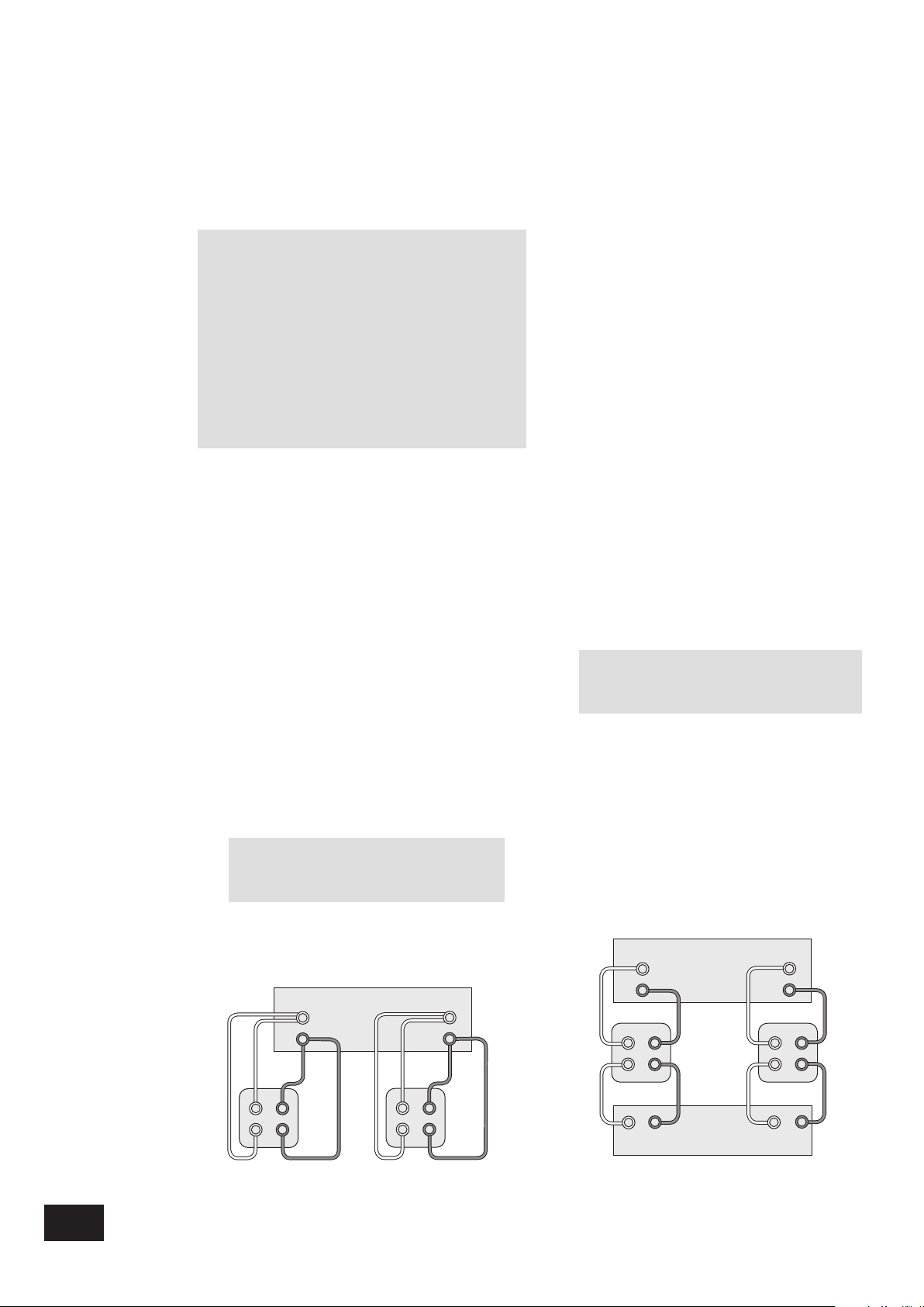
R
L
Enciente
droite
Arcam AVR100
HF
LF
+
+
–
–
+
–
HF
LF
+
+
–
–
+
–
Enciente
gauche
RL
Amplificateur Arcam P85
+ –+ –
R
L
Arcam AVR100
+
–
+
–
HF
LF
+
–
+
–
–
HF
LF
++–
–
Enciente
droite
Enciente
gauche
Référence
Bi-câblage et bi-amplifi cation des haut-parleurs
Avant de commence
ATTENTION: Ne pas effectuer de branchements sur
l’amplifi cateur pendant qu’il est en marche ou relié
au secteur.
Commencer par vérifi er soigneusement toutes les
prises, en s’assurant que les câbles ou les fi ls
dénudés ne sont pas en contact avec l’amplifi cateur
(ce qui pourrait provoquer des courts-circuits) et que
les (+) sont reliés aux (+) et les (-) aux (-).
S’assurer toujours que la commande de volume de
l’amplifi cateur est réglée sur le minimum avant de
lancer ces opérations.
Bi-câblage des haut-parleurs
Le bi-câblage améliore la qualité du son du système car il
répartit les courants des signaux hautes et basses fréquences
entre les différents câbles des haut-parleurs – ce qui évite la
distorsion des signaux découlant de l’interface de ces courants
dans un même câble, comme dans les systèmes câblés
classiques.
Equipements nécessaires :
Haut-parleurs avec quatre bornes d’entrée chacun, marquées
HF (Haute Fréquence) et LF (Basse Fréquence).
Câbles de haut-parleurs –Deux paires de câbles par hautparleur (qui peuvent être reliés à l’amplifi cateur si celui-ci ne
dispose que d’une paire de bornes de sortie par canal) ou
un jeu de câbles en faisceau (probablement préparé par votre
revendeur et pouvant être utilisé pour le bi-câblage sur une
seule longueur.)
Comment bi-câbler les haut-parleurs
1. Retirer les cosses des bornes à l’arrière des hautparleurs.
ATTENTION: Cette étape est capitale.
Elle évite que votre amplifi cateur soit
endommagé et que sa garantie soit annulée.
2. Brancher les câbles comme indiqué sur le schéma
ci-dessous, en s’assurant que les polarités sont
respectées.
Bi-amplifi cation du système
Pour améliorer encore les performances de votre système, vous
pouvez effectuer une opération supplémentaire, qui consiste
à étendre le principe et à inclure une amplifi cation séparée
pour les boîtiers de commande haute et basse fréquence dans
chaque enceinte.
Brancher l’AVR100 aux bornes haute fréquence (HF) et
l’amplifi cateur au bornes basse fréquence (LF).
Equipements nécessaires :
Enceintes : Quatre bornes d’entrée chacune (comme pour
le bi-câblage) marquées HF (Haute Fréquence) et LF (Basse
Fréquence).
Deux amplifi cateurs – dont un est le récepteur AVR100 et l’autre
un amplifi cateur Arcam (par exemple P75 ou P85).
Câbles haut-parleurs – Une paire de câbles par enceinte ou
un jeu de câbles en faisceau (probablement préparé par votre
fournisseur et pouvant être utilisé pour la bi-amplifi cation en une
seule longueur.)
Câbles de liaison – Une paire de câbles de liaison de bonne
qualité.
Comment monter un système bi-amplifi é.
1. Retirer les cosses des bornes du panneau arrière des
enceintes.
ATTENTION: Cette étape est capitale. Elle
évite que votre amplifi cateur soit endommagé
et que sa garantie soit annulée.
2. Brancher les câbles comme indiqué sur le schéma
ci-dessous, en s’assurant que les polarités sont
respectées.
3. Utiliser les câbles de liaison pour brancher les prises
AUDIO PRE-OUT du récepteur sur les prises « PWR AMP
IN » correspondantes de l’amplifi cateur.
AVR100
30
Schéma de bi-câblage
Schéma de bi-amplifi cation
Page 31

Dépannage
Le tableau suivant devait permettre de régler la plupart des problèmes qui peuvent se poser lors de l’utilisation du récepteur AVR100.
Problème
Pas de son
Pas de son sur un canal
Pas de détection
automatique du système
Dolby Digital or DTS
Absence de basses ou
mauvaise qualité d’image
stéréo
Pas de son en
provenance du tuner
Cause
1. Cordon d’alimentation non branché ou appareil non mis en
marche
2. En mode standby
3. Son coupé (fonction MUTE)
4. Moniteur de bande sélectionné
1. Enceinte non branchée ou mal branchée
2. Entrée non branchée ou mal branchée
3. Haut-parleur sur OFF dans la page SETUP
4. Niveau de canal trop faible
Entrée numérique non branchée
1. enceintes déphasés (par exemple, + connecté sur –, ou
rouge sur noir, par erreur ; erreur de polarité sur une
enceinte)
2. Haut-parleurs positionnés sur SMALL
1. Antenne mal branchée
2. Signal faible coupé par FM Mute
Solution
1. Vérifi er que le câble d’alimentation secteur est relié au
récepteur et que le sélecteur mural est sur Marche.
2. Appuyer sur le bouton POWER/STANDBY de la
télécommande.
3. Positionner la coupure du son sur Arrêt.
4. Appuyer sur le bouton TAPE MONITOR.
1. Vérifi er les raccordements à l’AVR100 et au haut-parleur
2. Vérifi er les raccordements à l’AVR100 et à la source.
3. Modifi er les réglages des haut-parleurs sur l’affi chage
écran.
4. Modifi er l’équilibrage des canaux sur l’affi chage écran.
Brancher la sortie numérique de la source sur l’entrée
appropriée du récepteur.
1. Vérifi er tous les raccordements au récepteur et aux
enceintes.
2. Re-sélectionner le pré-réglage des haut-parleurs sur
l’affi chage écran.
1. Vérifi er les raccordements de l’antenne sur le panneau
arrièrede l’appareil.
2. Mettre le sélecteur FM MUTE/MONO sur Arrêt ou re-régler
la station.
Français
La télécommande ne
fonctionne pas
L’image défi le sur
l’écran, ou est
uniquement en noir et
blanc
Pas d’image sur le
moniteur après la
sélection d’une
alimentation vidéo
Son et image provenant
de sources différentes
Passage automatique du
récepteur AVR100 en
mode « standby »
Le témoin d’état rouge
clignote et le récepteur
AVR100 semble ne pas
fonctionner.
1. Piles de la télécommande montées à l’envers ou
déchargées
2. Fenêtre récepteur IR AVR100 mal éclairée
3. Fenêtre récepteur IR trop éclairée
Mauvaise sélection du système vidéo
1. Source non fonctionnelle
2. Pas de raccordement vidéo entre l’équipement et le
récepteur AVR100
Mauvais raccordement du système sur les entrées du
récepteur AVR100
Système passé en mode protection suite à une surchauffe
des circuits, éventuellement provoquée par une mauvaise
circulation de l’air autour de l’appareil.
Le récepteur est passé en mode Protection, probablement
à la suite d’une surcharge ou d’un court-circuit au niveau
des sorties haut-parleurs.
1. Vérifi er le sens des piles / Remplacer les piles usées.
2. Eliminer la cause de l’’obstruction ».
3. Déplacer le récepteur par rapport à la source de lumière ou
le protéger de la lumière intense.
Appuyer sur le bouton STORE, maintenir le bouton enfoncé
tout en cliquant sur le bouton SAT pour alterner entre les
systèmes vidéo PAL et NTSC.
1. Vérifi er et activer la source d’alimentation.
2. Vérifi er le câblage du système pour s’assurer du
raccordement entre les équipements.
Vérifi er le câblage du système : s’assurer que tous les
câbles sont raccordés aux entrées correspondantes du
récepteur.
Couper l’alimentation du système. Supprimer tout ce qui
peut limiter la circulation de l’air. Laisser le système
refroidir avant de le brancher de nouveau.
Eteindre le récepteur et débrancher le câble d’alimentation
secteur. Vérifi er tous les câbles et vérifi er que des câbles
dénudés de haut-parleurs ne sont en contact ni les uns
avec les autres, ni avec le châssis. Rebrancher le câble
d’alimentation secteur et allumer la machine. Si le problème
persiste, contactez votre revendeur Arcam.
AVR100
31
Page 32

Spécifi cations techniques
SPECIFICATIONS AMPLIFICATEUR
Puissance de sortie (20Hz – 20kHz avec distorsion
harmonique totale (THD) de 0,5%)
8Ω, cinq canaux 70W
8Ω, deux canaux 90W
8Ω, un seul canal 100W
Distorsion harmonique, 1W, 8Ω a1kHz 0,02% type
Diaphonie G/D > 60dB à 1kHz
Réponse de fréquence ±1,0dB 20Hz à 20kHz
Entrées
Entrée de canal :
Sensibilité 200mV
Impédance d’entrée > 10kΩ
Marge de surcharge > 20dB
Sensibilité d’entrée de l’amplifi cateur 740mV (gain normal)
Sorties
Pré-amplifi cateur
Niveau de sortie nominal 200mV
Niveau de sortie maximum 3V
Casques
Impédance de sortie 390Ω
Caractéristiques physiques
Dimensions l x P x H 430 x 425 x 150mm
Poids net 11,9kg
Poids emballé 14,1kg
Tension secteur 230V ±12%
120V ±12%
Consommation électrique (max) 500VA
SPECIFICATIONS RADIO
Section FM
30 stations pré-réglées
Identifi cation station RDS, Affi chage des informations radio
Gamme réglages FM 87,5 à 108 MHz
Sensibilité FM < 6µV
Distorsion harmonique totale (THD)
Mono < 0,25%
Stéréo < 035%
Rapport Signal / Bruit
Mono > 72dB
Stéréo > 66dB
Suppression de tonalité d’identifi cation > 60dB
Sélectivité canal remplacement IHF > 60dB
Taux de capture < 3dB
Section AM
10 stations pré-réglées
Gamme de réglages AM
Etapes 10kHz 530 à 1710 kHz
Etapes 9kHz 531 à 1602 kHz
Sensibilité utilisable < 30µV
Rejet IF > 36dB
Rapport signal/bruit, entrée 5mV > 38dB
Distorsion harmonique totale (THD),
entrée 5 mV < 3%
AVR100
32
Accessoires fournis
Câble de liaison au secteur
Télécommande CR-340
2 piles AAA
Antenne cadre AM
Antenne à ruban FM
REMARQUE: sauf mention contraire, toutes les valeurs
spécifi ées sont des valeurs typiques.
Sauf erreurs ou omissions
Engagement d’amélioration continue
Arcam s’engage à améliorer continuellement ses produits. Ceci
signifi e que les dessins et spécifi cations peuvent faire l’objet de
modifi cations sans préavis.
Page 33

Garantie
Garantie mondiale
Cette garantie vous autorise à faire réparer gratuitement votre
récepteur chez un distributeur Arcam agréé durant les deux
premières années suivant l’achat, à condition que l’appareil ait
à l’origine été acheté chez un revendeur ou un distributeur
Arcam. Le fabricant ne peut engager sa responsabilité en cas
de défauts découlant d’un accident, d’une mauvaise utilisation,
d’une utilisation intensive, d’une usure normale, d’une négligence
ou d’un réglage ou d’une réparation non autorisée. Il ne peut
également pas non plus engager sa responsabilité pour tout
dommage ou toute perte survenant pendant le transport du
matériel sous garantie.
Etendue de la garantie
La garantie couvre le coût des pièces et de la main-d’oeuvre
pendant les 2 ans suivant la date d’achat. Passé deux ans, ces
frais incombent au client. La garantie ne couvre jamais les frais
de transport.
Réclamations acceptées au titre de la garantie
L’appareil doit être réexpédié dans son emballage d’origine et
renvoyé au revendeur auquel il a été acheté, ou directement au
distributeur Arcam dans le pays de résidence du client.
Il doit être expédié port payé par un transporteur connu, et NON
par la poste. Aucune responsabilité n’est acceptée pendant le
transport de cet équipement au titre de la garantie ; en outre, il
est conseillé aux clients de prendre les assurances nécessaires
contre les pertes et dommages subis lorsque l’appareil est en
transit.
Pour toutes informations complémentaires, veuillez
contacter le Service client Arcam à l’adresse
suivante :
Pembroke Avenue, Waterbeach, CAMBRIDGE
CB5 9PB, Angleterre.
Téléphone: +44 (0)1223 203203 Fax: +44 (0)1223 863384
Email: support@arcam.co.uk
Problèmes !
Si votre revendeur ne peut pas répondre aux questions
concernant ce récepteur ou tout autre produit Arcam, contacter
notre Service Client Arcam au +44 (0) 1223 203203 ou écrire
à l’adresse ci-dessus, afi n que nous puissions traiter votre
problème au mieux.
Français
Enregistrement sur Internet
Vous pouvez enregistrer votre produit Arcam à l’adresse
suivante :
www.arcam.co.uk/reg
AVR100
33
Page 34

Sicherheitsrichtlinien
Sicherheitsrichtlinien
Dieses Gerät wurde unter Berücksichtigung strikter Qualitätsund Sicherheitsbestimmungen entworfen und gefertigt. Sie
sollten jedoch bei der Installation und dem Betrieb folgende
Vorsichtsmaßnahmen treffen:
1. Beachten Sie Warnungen und Anweisungen.
Vor der Inbetriebnahme dieses Gerätes sollten Sie die
entsprechenden Sicherheits- und Betriebsanweisungen lesen.
Heben Sie dieses Handbuch gut auf, und beachten Sie die
enthaltenen Warnungen sowie die Hinweise auf dem Gerät.
2. Wasser und Feuchtigkeit.
Das Betreiben von elektrischen Geräten in der Nähe von
Wasser kann gefährlich sein. Verwenden Sie das Gerät nicht in
einer feuchten Umgebung (z.B. in der Nähe von Badewannen,
Waschbecken, Swimming Pools oder in einem feuchten Keller).
3. Eindringen von Gegenständen oder Flüssigkeiten.
Achten Sie darauf, dass keine Gegenstände oder Flüssigkeiten
in die Öffnungen des Gerätes geraten. Sie sollten keine mit
Flüssigkeit gefüllten Behälter (z.B. Blumenvasen) auf dem Gerät
abstellen.
4. Belüftung.
Stellen Sie das Gerät nicht auf ein Bett, ein Sofa, einen
Teppich oder eine andere weiche Oberfl äche, oder in ein
abgeschlossenes Bücherregal bzw. einen Schrank, da hierdurch
die Belüftung beeinträchtigt werden könnte. Es wird empfohlen,
einen Mindestabstand von 50 mm um die Seiten- und
Oberkanten des Geräts freizuhalten.
5. Wärme.
Stellen Sie das Gerät nicht in der Nähe von offenem Feuer oder
Wärme abgebenden Geräten wie Heizkörpern, Herden oder
anderen Elektrogeräten (z.B. anderen Verstärkern) auf.
6. Klima
Das Gerät wurde für den Betrieb in gemäßigten Klimazonen
ausgelegt.
7. Racks und Regale.
Benutzen Sie nur Racks und Regale, die für die Verwendung
mit Audiogeräten geeignet sind. Bewegen Sie die Anlage sehr
vorsichtig, wenn sie sich auf einem fahrbaren Regal befi ndet,
um ein Umfallen zu vermeiden.
9. Stromversorgung.
Verwenden Sie nur eine Stromquelle, die den Hinweisen im
Handbuch oder auf dem Gerät entspricht.
10. Schutz der Netzkabel.
Verlegen Sie die Netzkabel nicht frei im Raum. Achten Sie
darauf, dass sie nicht geknickt oder gedehnt werden und
dass keine Gegenstände darauf zu stehen kommen. Gehen
Sie besonders sorgfältig mit Kabelenden an Steckern und
Gerätebuchsen um.
11. Erdung.
Achten Sie darauf, dass die Erdung des Gerätes nicht
beeinträchtigt wird.
12. Stromleitungen.
Bringen Sie Außenantennen nicht in der Nähe von
Stromleitungen an.
13. Nichtnutzung.
Ist die Anlage mit einem Standby-Modus ausgestattet, fl ießt in
diesem Modus ein geringer Strom durch das Gerät. Ziehen Sie
den Netzstecker, wenn Sie das Gerät für längere Zeit nicht
nutzen.
14. Seltsamer Geruch.
Sollten Sie einen ungewöhnlichen Geruch bemerken oder Rauch
am Gerät entdecken, schalten Sie es aus und ziehen Sie den
Netzstecker. Wenden Sie sich dann sofort an Ihren Fachhändler.
15. Wartung.
Sie sollten nicht versuchen, das Gerät selbst zu warten. Führen
Sie nur die in diesem Handbuch beschriebenen Maßnahmen aus.
Überlassen Sie die Wartung des Gerätes einem Fachmann.
16. Zu behebende Schäden.
Das Gerät sollte von einem Fachmann gewartet werden, wenn:
A. das Netzkabel oder der Netzstecker beschädigt wurde,
oder
B. Gegenstände in das Gerät gefallen oder Flüssigkeiten
eingedrungen sind, oder
C. das Gerät Regen ausgesetzt war, oder
D. das Gerät nicht ordnungsgemäß funktioniert oder einen
erheblichen Leistungsabfall aufweist, oder
C. das Gerät fallen gelassen wurde oder das Gehäuse
beschädigt ist.
AVR100
34
8. Reinigung.
Ziehen Sie vor dem Reinigen des Gerätes den Netzstecker.
In den meisten Fällen reicht es aus, wenn Sie das Gehäuse
mit einem weichen, fusselfreien und angefeuchteten Tuch
abwischen. Verwenden Sie keine Verdünner oder andere
chemische Lösungsmittel.
Von der Verwendung von Polituren oder Möbelsprays wird
abgeraten, da diese Substanzen weiße Spuren hinterlassen
können, wenn das Gerät danach mit einem feuchten Tuch
abgewischt wird.
Einhaltung von Sicherheitsbestimmungen.
Dieses Gerät entspricht der internationalen Sicherheitsnorm für
Elektrogeräte EN60065.
Page 35

Hinweise zum Handbuch
Dieses Handbuch enthält die Informationen, die Sie zum
Installieren, Anschließen, Einrichten und Betreiben des Arcam
AVR100 Surround-Sound-Empfängers benötigen. Außerdem wird
die mitgelieferte Fernbedienung beschrieben.
Sollte Ihr AVR100 von einem qualifi zierten Arcam-Händler
als Teil Ihrer HiFi-Anlage installiert worden sein, können Sie
die Abschnitte zum Installieren und Einrichten des Gerätes
überspringen. Das Inhaltsverzeichnis (auf dieser Seite) gibt Ihnen
einen Überblick über die Abschnitte des Handbuches.
Sicherheit
Auf der Innenseite des Deckblattes fi nden Sie die
Sicherheitsrichtlinien.
Vieles davon scheint zwar offensichtlich, Sie sollten die Hinweise
aber trotzdem lesen, damit das Gerät nicht beschädigt wird.
Inhalt
Sicherheitsrichtlinien 34
Sicherheitsrichtlinien 34
Einhaltung von Sicherheitsbestimmungen 34
Hinweise zum Handbuch 35
Sicherheit 35
Installation 36
Aufstellen des Geräts 36
Einrichten der Antennen 36
Anschließen der Eingänge 37
Anschlüsse auf der Rückseite des AVR100 37
Verbindungskabel 37
Anschließen der Ausgänge 38
Anschließen anderer Geräte 38
Anschließen der Stromversorgung 38
Einrichten des Geräts 39
Das On Screen Display (OSD) 39
Seite „SETUP” 39
Seite „INPUT SETTINGS” 39
Seite „CHANNEL BALANCE” 39
Seite „CHANNEL DELAYS” 39
Seite „SPEAKER SETTINGS” 39
Der AVR100 40
Steuerelemente an der Vorderseite 40
Auswählen der Eingänge 40
Der Tuner 41
Suchen eines Senders 41
Speichern eines Senders 41
Löschen eines ungenutzten Senders 41
RDS: Radio Data System 42
FM MUTE/MONO 42
Die Fernbedienung 43
Die Fernbedienung CR-340 43
Zusätzliche Informationen 44
Bi-Wiring und Bi-Amping der Lautsprecher 44
Erste Schritte 44
Bi-Wiring der Lautsprecher 44
Bi-Amping der Anlage 44
Fehlerbehebung 45
Technische Daten 46
Garantie 47
Online-Registrierung 47
Deutsch
Hergestellt unter Lizenz von Dolby Laboratories, Inc.
„Dolby”, „AC3”, „Pro Logic” und das Doppel-D-Logo sind
Warenzeichen der Dolby Laboratories.
Copyright © 1992 Dolby Laboratories, Inc. Alle Rechte
vorbehalten.
Hergestellt unter Lizenz von Digital Theater Systems, Inc.
US-Patentnummer 5,451,942 (andere weltweite Patente
ausgestellt oder eingereicht). „DTS” und „DTS Digital Surround”
sind Warenzeichen von Digital Theater Systems, Inc.
Copyright © 1996 Digital Theater Systems, Inc. Alle Rechte
vorbehalten.
AVR100
35
Page 36

Installation
Zuerst müssen Sie das Gerät an einem geeigneten Standort
aufstellen. Wenn Sie den Radioempfänger nutzen wollen,
müssen Sie außerdem eine UKW- bzw. MW-Antenne installieren.
Andere Eingangssignale (CD, MD, Kassette, DAT, VCR, DVD,
Spielekonsole oder Satellitenempfänger) müssen an den
entsprechenden Buchsen auf der Rückseite des AVR100
angeschlossen werden.
Ausgangssignale (Fernseher, Monitor, Projektor, Vorverstärker,
Lautsprecher oder andere Audio- bzw. Digitalausgänge) müssen
ebenfalls an der Geräterückseite angeschlossen werden.
Aufstellen des Gerätes.
Stellen Sie den AVR100 auf eine ebene, stabile Oberfl äche.
Sie sollten das Gerät vor direkter Sonneneinstrahlung schützen
und von Wärme- bzw. Feuchtigkeitsquellen fernhalten.
Sorgen Sie für eine ausreichende Belüftung. Platzieren Sie das
Gerät nicht in einem Bücherregal oder Schrank, da sonst die
Luftzufuhr zu den Lüftungsschlitzen beeinträchtigt wird.
Einrichten der Antennen
UKW-Antenne
Zum Empfang von VHF-Radiosignalen benötigen Sie eine UKWAntenne. Eine externe UKW-Bandantenne ist im Lieferumfang
des AVR100 enthalten.
Für einen optimalen Empfang empfehlen wir eine Außenantenne
auf dem Dach. Zu Ihrer eigenen Sicherheit sollten Sie eine
solche Antenne nur von einem Fachmann installieren lassen.
Ihr Arcam-Händler kann Sie in dieser Hinsicht beraten. Der
Fachmann kann die Antenne auf den naheliegendsten UKWUmsetzer einstellen. Wenn Sie in einem Mehrparteienhaus
wohnen, ist evtl. bereits eine Hausanlage installiert. In
diesem Fall sollten Sie in Ihrer Wohnung eine entsprechende
Anschlussmöglichkeit haben.
Die mitgelieferte T-förmige Drahtantenne (Dipol) sollte einen
relativ guten Empfang ermöglichen. Befestigen Sie diese
Antenne so hoch wie möglich an einer Wand. Die Elemente
sollten horizontal angebracht werden. Testen Sie die Antenne
an jeder Wand, um die Stelle mit dem besten Empfang zu
fi nden. Benutzen Sie Klebeband oder Reißnägel, um die
Antenne T-förmig anzubringen. Achten Sie dabei darauf, dass
die Reißnägel nicht mit dem Antennendraht in Berührung
kommen.
Sowohl die Dachantenne als auch die Drahtantenne muss an der
Buchse „FM ANTENNA” auf der Geräterückseite angeschlossen
werden.
MW-Antenne
Zum Empfang von MW/AM-Radiosignalen benötigen Sie
eine MW-Antenne. Eine externe MW-Rahmenantenne ist im
Lieferumfang des AVR100 enthalten.
Schließen Sie diese Antenne an den Buchsen „AM” und „GND”
an. Die Polung der Antenne spielt keine Rolle. Drehen Sie die
Antenne, bis Sie den besten Empfang erhalten.
In Gebieten mit schwachem Empfang oder in Gebäuden mit
Stahlbeton können Sie einen drei bis fünf Meter langen Draht
verwenden, um den Empfang zu verbessern. Bringen Sie
diesen Draht so hoch wie möglich an der Außenseite des
Gebäudes an, und schließen Sie ein Ende des Drahtes an der
Antennenbuchse „AM” zusammen mit der Rahmenantenne an.
Die Rahmenantenne MUSS angeschlossen bleiben.
Den Schrittabstand müssen Sie entsprechend Ihrem Standort
über den Schalter auf der Geräterückseite einstellen: Wählen Sie
10 kHz für Nordamerika oder 9 kHz für alle anderen Regionen.
AVR100
36
Page 37

Anschließen der Eingänge
AC INLET
SURROUND
LR
+
–
CENTREFRONT
LR
+
–
OUT
VCR
IN
IN
DVD
IN
SAT
IN
AUX
OUT
(N.AM)10K
AM STEP
GROUND
LIFT
SPEAKER
IMPEDANCE
SELECTOR
4–6Ω 8Ω
GROUND
120V 230V
LOUDSPEAKER
OUTPUTS
SUB
WOOFER
CENTER
AUDIO VIDEO S-VIDEO
S-VIDEO
VIDEO
AUDIO
PRE-OUT
CD
TAPE 5.1 CH INPUT
SUB
WOOFER
CENTER
IN
IN
OUT
AUDIOR
(EU) 9K
L
LRLR
R L
FM
GND
AM
ANTENNA
MONITOR OUT
FRONT SURR FRONT SURR
DIGITAL
IN
VCR DVD SAT
Verbindungskabel
Um die beste Klang- und Bildqualität zu gewährleisten,
empfehlen wir, zum Anschließen der Komponenten am AVR100
hochwertige Verbindungskabel zu verwenden. Ihr Arcam-Händler
berät Sie gerne.
Dieses Gerät besitzt keine Phono-Eingänge. Wenn Sie einen
Plattenspieler anschließen möchten, müssen Sie einen in Reihe
geschalteten Phono-Vorverstärker verwenden. Alle Line-Eingänge
sind gleich empfi ndlich, Sie können also beliebige Geräte
mit einem Line-Ausgang anschließen, auch solche, die nicht
gekennzeichnet sind. Wenden Sie sich im Zweifelsfall an Ihren
Arcam-Händler.
CD-Eingang.
Verwenden Sie Audiokabel zum Anschließen der linken und
rechten Audioausgänge des CD-Spielers an die CD-Eingänge des
AVR100.
TAPE-Schleife.
Hier können Sie verschiedene Aufnahmegeräte anschließen, z.B.
Kassettendeck, Mini-Disc oder CD-R. Verwenden Sie Audiokabel
zum Anschließen der linken und rechten Audioausgänge des
Aufnahmegerätes an den TAPE-Eingängen des AVR100.
Schließen Sie zum Vervollständigen der Aufnahmeschleife
die TAPE-Ausgänge des AVR100 an den Eingängen des
Aufnahmegerätes an.
5.1 CH INPUT
Dieser Mehrkanaleingang nimmt bis zu sechs (fünf Kanäle
plus ein Subwoofer) getrennte Audiokanäle von einem DVDAudiospieler bzw. einem DVD-Spieler mit integriertem Dekoder
auf. Verwenden Sie Audiokabel zum Anschließen der linken und
rechten Audioausgänge des DVD-Geräts an den 5.1 CH INPUTEingängen des AVR100.
Um eine optimale Wiedergabe von DVD-Video zu gewährleisten,
sollten Sie jedoch den Digitalanschluss zum internen digitalen
Surround-Dekoder des AVR100 verwenden.
SAT-Eingang
Verwenden Sie Audiokabel zum Anschließen der linken
und rechten Audioausgänge des (digitalen) Satelliten- oder
Kabelempfängers an den SAT-Eingängen des AVR100.
Verbinden Sie entweder den Composite- oder S-Video-Ausgang
des Satellitenempfängers mit dem entsprechenden VIDEO- oder
S-VIDEO-Eingang des AVR100.
Besitzt Ihr Satellitenempfänger einen koaxialen Digitalausgang,
verbinden Sie diesen mit dem digitalen SAT-Eingang.
DVD-Eingang
Sie erhalten normalerweise die beste Audioqualität, wenn Sie
den digitalen Ausgang des DVD-Spielers über ein passendes
75Ω-Digitalkabel mit dem digitalen DVD-Eingang des AVR100
verbinden. Verbinden Sie entweder den Composite- oder
S-Video-Ausgang des DVD-Spielers mit dem entsprechenden
VIDEO- oder S-VIDEO-Eingang des AVR100.
Wenn Sie mit dem DVD-Spieler auch CDs abspielen und die
Stereo-Audioausgänge nutzen wollen, verbinden Sie diese mit
den CD-Eingängen des AVR100.
VCR-Schleife.
Verwenden Sie Audiokabel zum Anschließen der linken
und rechten Audioausgänge des Videorecorders an den
VCR-Eingängen des AVR100. Verbinden Sie entweder den
Composite- oder S-Video-Ausgang des Videorecorders mit dem
entsprechenden Eingang des AVR100. Hat der Videorecorder
einen digitalen Ausgang, schließen Sie ihn am digitalen VCREingang des AVR100 an.
Schließen Sie zum Vervollständigen der Aufnahmeschleife
die VCR-Ausgänge des AVR100 an den Eingängen des
Videorecorders an. Verbinden Sie über eine Videoverbindung
desselben Typs den VCR-Ausgang des AVR100 mit dem
entsprechenden Eingang des Videorecorders.
AUX-Eingang und -Aufnahmeschleife
Verwenden Sie Audiokabel zum Anschließen der linken und
rechten Audioausgänge einer anderen Quelle (z.B. eines anderen
Audiogerätes oder einer Spielekonsole) an den AUX-Eingängen
des AVR100. Hat die Quelle einen Composite-Videoausgang,
verbinden Sie diesen mit dem entsprechenden AUX-Eingang.
Handelt es sich bei der Zusatzquelle um ein Aufnahmegerät,
vervollständigen Sie die Aufnahmeschleife, indem Sie die
linken und rechten AUX-Ausgänge mit den Aufnahmeeingängen
des Aufnahmegerätes verbinden. Verbinden Sie bei einem
Videorecorder den Composite-Videoausgang (AUX) mit dem
entsprechenden Eingang des Recorders.
GROUND LIFT-Schalter
Wenn an der Anlage nur Audioquellen von CD oder DVD
angeschlossen sind, stellen Sie diesen Schalter auf „GROUND”.
Bei komplexeren Anlagen mit Satelliten- oder Radioquellen
könnte die Lautstärke des Hintergrundbrummens in den
Lautsprechern zunehmen, wenn das Gerät geerdet ist. Stellen
Sie dann den Schalter auf „GROUND LIFT”.
Deutsch
AVR100
37
Page 38

Anschließen der Ausgänge
Anschließen anderer Geräte
Monitorausgang.
Für den Anschluss am Videoeingang eines Fernsehers, Monitors
oder Projektors sind Composite- und S-Video-Monitorausgänge
vorhanden. Sind am AVR100 sowohl Composite- als auch
S-Video-Quellen angeschlossen, müssen Sie nur die Buchse
S-VIDEO-MONITOR OUT mit Ihrem Fernseher verbinden,
vorausgesetzt, dieser kann S-Videosignale verarbeiten.
Lautsprecherausgänge.
Bevor Sie die Lautsprecher am AVR100 anschließen, müssen
Sie den Impedanzschalter korrekt einstellen.
Warnung: Stellen Sie den Schalter nie bei
eingeschaltetem Gerät um, da der AVR100 sonst
beschädigt wird.
Liegen die Lautsprecher bei 6W oder darunter, stellen Sie den
Schalter auf die Position „4–6W”. Liegen die Lautsprecher bei
mehr 6W, stellen Sie den Schalter auf die Position „8W”.
Warnung: Sie sollten nur Lautsprecher mit einer
Impedanz zwischen 4 und 8W verwenden.
Der AVR100 ist mit Lautsprecheranschlüssen ausgestattet, die
den Normen der BFA (British Federation of Audio) entsprechen.
Sie können die Lautsprecher über Flachstecker, blanken Draht
oder einen BFA-Stecker anschließen. Schrauben Sie zum
Anschließen von Flachsteckern oder blankem Draht das Ende
des Anschlusses ab, führen Sie den Stecker oder den Draht
ein und schrauben Sie den Anschluss wieder fest. Achten Sie
darauf, dass keine losen Litzen andere Kabel oder das Gehäuse
des AVR100 berühren, da dies einen Kurzschluss auslösen und
den Verstärker beschädigen kann.
Anschließen der Stromversorgung.
Falscher Netzstecker?
Prüfen Sie, ob der Netzstecker zu Ihrer Stromversorgung
passt und die Netzspannung mit der Einstellung auf der
Geräterückseite (120 oder 230 V) übereinstimmt.
Stimmt Ihre Netzspannung nicht überein, wenden Sie sich an
Ihren Arcam-Händler oder den Arcam-Kundendienst unter +44
(0)1223 203203.
Anschließen
Drücken Sie den IEC-Stecker des mitgelieferten Netzkabels fest
in die Netzbuchse an der Geräterückseite (AC INLET).
Stecken Sie das andere Ende des Netzkabels in eine
Netzsteckdose.
Nichtnutzung.
Wenn Sie das Gerät über einen längeren Zeitraum nicht
nutzen, empfehlen wir, es mit dem Netzschalter an der
Gerätevorderseite auszuschalten, anstatt nur den StandbyModus über die Fernbedienung zu aktivieren.
Bi-Wiring und Bi-Amping der Lautsprecher
Anweisungen hierzu fi nden Sie im Abschnitt „Zusätzliche
Informationen”.
Vorverstärkerausgänge
Wenn Sie Ihre Anlage um weitere Verstärker erweitern möchten,
sollten Sie immer Geräte von Arcam verwenden, um die
passende Verstärkung zu erhalten.
Der AVR100 hat sechs Line-Vorverstärkerausgänge, an die
externe Endverstärker von Arcam angeschlossen werden
können. So kann ein beliebiger Kanal mit zwei Verstärkern
betrieben werden („Bi-Amping”). Sie können den AVR100 auch
nur als Vorverstärker nutzen.
Je nach Konfi guration sollte der Subwoofer-
ein Line-Verbindungskabel entweder an:
PRE-AMP OUT über
■ einen Aktiv-Subwoofer oder
■ an einen Endverstärker angeschlossen werden, der einen
passiven Subwoofer betreibt.
Kopfhörerausgang
An der Gerätevorderseite befi ndet sich eine 6,3
mm-Stereobuchse zum Anschließen eines Kopfhörers. Wenn
ein Stecker angeschlossen wird, werden die Lautsprecherund Vorverstärkerausgänge des AVR100 automatisch stumm
geschaltet.
AVR100
38
Page 39

1 INPUT SETTINGS
2 CHANNEL BALANCE
3 CHANNEL DELAYS
4 SPEAKER SETTINGS
5 EXIT
SETUP
1 INPUT SETTINGS
2 CHANNEL BALANCE
3 CHANNEL DELAYS
4 SPEAKER SETTINGS
5 EXIT
SETUP
AUDIO = DVD
VIDEO = DVD
MODE = DOLBY DIGITAL
DYNAMIC RANGE = 100%
DO NOT SAVE AND EXIT
SAVE AND EXIT
INPUT SETTINGS
1 INPUT SETTINGS
2 CHANNEL BALANCE
3 CHANNEL DELAYS
4 SPEAKER SETTINGS
5 EXIT
SETUP
LEFT : 0dB
CENTER : 0dB
RIGHT : 0dB
REAR L : 0dB
REAR R : 0dB
SUB : 0dB
DO NOT SAVE AND EXIT
SAVE AND EXIT
CHANNEL BALANCE
Einrichten des Geräts
Das On Screen Display (OSD)
Die einfachste Möglichkeit zum Einstellen der Mehrkanal-Audiound Videooptionen des AVR100 ist das „On Screen Display”
(OSD).
Schließen Sie zum Aufrufen des OSD einen Fernseher an
und drücken Sie einen der Pfeile auf dem Cursorblock der
Fernbedienung.
Verwenden Sie zum Auswählen einer Option auf der ersten
Seite (SETUP – Einrichten) die Pfeile
•
und •, um eine
Zeile zu markieren. Drücken Sie „OK”, um die markierte Seite
aufzurufen. Markieren Sie zum Beenden des OSD die Option
„EXIT” (Beenden) und drücken Sie „OK”.
•
Auf den Seiten können Sie mit den Tasten
und •
eine Zeile markieren und mit den Tasten • und • die
entsprechende Option ändern. Wenn Sie die gewünschten
Einstellungen vorgenommen haben, markieren Sie „SAVE AND
EXIT” (Speichern und beenden)und drücken Sie „OK”, um sie
zu speichern. Wenn Sie sich nicht sicher sind oder die Seite
versehentlich aufgerufen haben, markieren Sie „DO NOT SAVE
AND EXIT” (Nicht speichern und beenden) und drücken Sie „OK”.
Etwaige Änderungen auf dieser Seite werden ignoriert.
Seite „SETUP”
Die Seite „SETUP” ist das Inhaltsverzeichnis des OSD.
Verwenden Sie zum Aufrufen der einzelnen Optionen den
Cursorblock der Fernbedienung.
Die Lautsprecher können in einem Bereich zwischen +10dB und
–10dB geregelt werden.
Sie können jederzeit zur Seite „CHANNEL BALANCE”
zurückkehren, indem Sie die TEST-Taste auf der Fernbedienung
drücken, ohne das OSD aufrufen zu müssen. Drücken Sie zum
Verlassen dieser Seite erneut die TEST-Taste.
Hinweis: Es kann vorkommen, dass das OSD-Bild bzw. der
Lautstärkebalken nicht ruhig ist und über den Bildschirm
„wandert”. In diesem Fall müssen Sie das vom AVR100
genutzte Farbsystem umstellen.
Beenden Sie zuerst das OSD, indem Sie die Option
„EXIT” markieren und „OK” drücken. Halten Sie die Taste
„STORE” (Speichern) auf der Gerätevorderseite gedrückt,
und schalten Sie zwischen den angezeigten Systemen um,
indem Sie die Taste „SAT” drücken, bis das richtige System
erscheint: NTSC für Nordamerika oder PAL für den Großteil
von Europa.
Deutsch
Seite „INPUT SETTINGS”
(Eingangseinstellungen)
AUDIO Bestimmt die aktive Audioquelle (CD,
Tuner, SAT, VCR usw.)
VIDEO Bestimmt die aktive Videoquelle (SAT,
DVD, VCR oder AUX)
MODE (Modus) Bestimmt den Surround-Modus für den
aktuellen Eingang (Dolby Digital, DTS,
Dolby Pro Logic, Hall effect oder Stereo)
DYNAMIC RANGE Ein komprimierter Dynamikbereich
(Dynamikbereich) ermöglicht leise Wiedergabe, z.B. in
Nacht. Für Dolby Digital-Quellen gibt
es die Dynamikbereiche 100%, 75%,
50% oder 25%.
Seite „CHANNEL BALANCE”
(Kanalbalance)
Auf der Seite „CHANNEL BALANCE” können Sie die Lautstärke
für jeden am AVR100 angeschlossenen Lautsprecher einzeln
einstellen. Aufgrund unterschiedlicher Leistungsmerkmale oder
Positionierungen der Lautsprecher müssen sie evtl. auf
verschiedene Lautstärken eingestellt werden, um einen
ausgeglichenen Klang an der Hörposition zu gewährleisten. Um
das Einstellen der Balance zu erleichtern, kann der AVR100
einen Testton erzeugen, der ein identisches Signal nacheinander
über jeden Kanal sendet.
Wenn die Seite „CHANNEL BALANCE” auf dem OSD erscheint,
drücken Sie auf der Fernbedienung die Taste „TEST”, um den
Testton zu starten. Dabei muss die Lautstärke am AVR100 so
hoch eingestellt sein, dass der Ton hörbar ist. Der Testton
wird automatisch nacheinander über alle Lautsprecherkanäle
gesendet, bis Sie die TEST-Taste erneut drücken.
Hinweis: Der Testton erzeugt ein Geräusch, das evtl. über
den Subwoofer nicht hörbar ist. Schalten Sie zum Einstellen
des Subwoofer den Testton ab, spielen Sie einen vertrauten
Musiktitel und experimentieren Sie mit den Einstellungen,
bis Sie zufrieden sind. Es gibt keine richtige oder falsche
Einstellung für den Subwoofer, suchen Sie einfach die
Einstellung, die Ihnen am besten gefällt.
AVR100
39
Page 40

Seite „CHANNEL DELAYS”
1 INPUT SETTINGS
2 CHANNEL BALANCE
3 CHANNEL DELAYS
4 SPEAKER SETTINGS
5 EXIT
SETUP
CENTER 0mS
REAR 0mS
DO NOT SAVE AND EXIT
SAVE AND EXIT
CHANNEL DELAYS
CENTER 3ms
REAR 6ms
DO NOT SAVE AND EXIT
SAVE AND EXIT
CHANNEL DELAYS
CHANNEL DELAYS
CENTER N/A
REAR 21ms
DO NOT SAVE AND EXIT
SAVE AND EXIT
mitte
Vorne
links
Vorne
rechts
z. B. 3mz. B. 4m
z. B. 2m
Hinten
rechts
Hinten
links
Um bei einem Surround-Sound-System das beste Ergebnis zu
erzielen, sollte der Ton aus allen Lautsprechern gleichzeitig
beim Hörer ankommen. Sie können daher im Dolby Digital- oder
Dolby Pro Logic-Modus leichte Verzögerungen einstellen.
Beim Wiedergeben einer Dolby Digital-Quelle können Sie für
den mittleren Kanal eine Verzögerung zwischen 0 und 5 ms und
für die hinteren Kanäle zwischen 0 und 15 ms einstellen.
Messen oder schätzen Sie zum Berechnen dieser
Verzögerungszeiten zunächst den Abstand von der Hörposition
zur Position der vorderen, mittleren und hinteren Lautsprecher.
Notieren Sie diese Abstände in der Spalte „Meine Werte” in der
nebenstehenden Tabelle.
Die Verzögerung des mittleren Kanals wird berechnet durch
Subtraktion des Abstands zwischen Hörposition und mittlerem
Lautsprecher vom Abstand zwischen Sitzposition und dem
vorderen linken (bzw. rechten) Lautsprecher. Der Unterschied
entspricht der Verzögerung „CENTRE” (Mitte).
Die Verzögerung der hinteren Kanäle wird berechnet durch
Subtraktion des Abstands zwischen Hörposition und hinterem
linken (bzw. rechten) Lautsprecher vom Abstand zwischen
Hörposition und vorderem linken (bzw. rechten) Lautsprecher.
Der Unterschied entspricht der Verzögerung „REAR” (Hinten).
Beachten Sie, dass Sie die Verzögerung auf 0 ms stellen
sollten, wenn die hinteren Lautsprecher weiter von der
Sitzposition entfernt sind als die vorderen.
AVR100
40
Ein Abstand von einem Meter entspricht ungefähr einer
Verzögerung von drei Millisekunden (3 ms).
Abstand zur Hörposition z. B. Ihre Werte
Vorne links oder rechts 4m --------------------Mitte 3m --------------------Hinten links oder rechts 2m ---------------------
Abstand z. B. Verzögerung (ms)
CENTRE-Verzögerung (4 – 3m)
= 1m 3 Millisekunden
REAR-Verzögerung (4 – 2m)
= 2m 6 Millisekunden
Beim Wiedergeben einer Dolby Pro Logic-Quelle können Sie
für die hinteren Kanäle eine Verzögerung zwischen 15 und 30
ms einstellen. Für den mittleren Kanal ist keine Verzögerung
möglich.
Die Verzögerung für den hinteren Kanal bei Dolby Pro Logic
wird berechnet durch Addition von 15 ms zum entsprechenden
Abstand bei Dolby Digital. In unserem Beispiel wäre das 15 ms
+ 6 ms = 21 ms.
Hinweis: Bei einer DTS-Quelle (Digital Theater Systems)
muss keine Verzögerung eingestellt werden.
Page 41

Seite „SPEAKER SETTINGS”
1 INPUT SETTINGS
2 CHANNEL BALANCE
3 CHANNEL DELAYS
4 SPEAKER SETTINGS
5 EXIT
SETUP
SPEAKER SETTINGS
PRESET : 1
MAIN : LARGE
CENTER : LARGE
SURROUND : LARGE
SUBWOOFER : ON
DO NOT SAVE AND EXIT
SAVE AND EXIT
SPEAKER SETTINGS
PRESET : 1
MAIN : LARGE
CENTER : LARGE
SURROUND : LARGE
SUBWOOFER : ON
DO NOT SAVE AND EXIT
SAVE AND EXIT
SPEAKER SETTINGS
PRESET : 2
MAIN : LARGE
CENTER : SMALL
SURROUND : SMALL
SUBWOOFER : OFF
DO NOT SAVE AND EXIT
SAVE AND EXIT
SPEAKER SETTINGS
PRESET : 3
MAIN : SMALL
CENTER : SMALL
SURROUND : SMALL
SUBWOOFER : ON
DO NOT SAVE AND EXIT
SAVE AND EXIT
(Lautsprechereinstellungen)
Auf dieser Seite des OSD wird die Größe und die Anzahl der
Lautsprecher bestimmt.
– Ein „LARGE” (großer) Lautsprecher kann den vollen
Frequenzbereich abdecken (d.h. 20 Hz – 20 kHz).
– Ein „SMALL” (kleiner) Lautsprecher kann keine Tiefen
erzeugen (d.h. Signale unter 100 Hz).
– Wählen Sie „ON” (Ein), wenn der Lautsprecher aktiv ist und
die Audiosignale empfängt.
– Wählen Sie „OFF” (Aus), wenn der Lautsprecher nicht aktiv
ist. Audiosignale, die an Lautsprecher angelegt werden,
die auf „OFF” stehen, werden an die Hauptlautsprecher
umgeleitet.
Voreinstellungen für typische
Lautsprecherkombinationen.
Um das Einrichten einfacher zu gestalten, sind im Arcam
AVR100 drei Lautsprecherkombinationen voreingestellt
(Presets).
Wählen Sie die Voreinstellung, die Ihrer Anlage am ehesten
entspricht.
■ PRESET 1 – große Lautsprecher und ein Subwoofer.
Mit dieser Voreinstellung werden Signale mit vollem
Frequenzumfang an jeden Lautsprecher geschickt.
Der Subwoofer unterstützt die Wiedergabe von
niederfrequenten Tönen.
Deutsch
■ PRESET 2 – große Lautsprecher vorne links und rechts,
kleine Lautsprecher in der Mitte und hinten.
Bei dieser Einstellung werden die niedrigen Frequenzen
für die Surround- und mittleren Kanäle an die
Hauptlautsprecher umgeleitet. Ein Subwoofer wird nicht
unterstützt.
■ PRESET 3 – kleine Lautsprecher und ein Subwoofer.
Diese Einstellung ist für Anlagen mit fünf kleinen
Lautsprechern und einem Subwoofer gedacht. Die Tiefen
werden von allen Kanälen auf den Subwoofer umgeleitet.
Nachdem Sie die gewünschte Einstellung gewählt haben, können
Sie die mittleren und Surround-Lautsprecher auf „OFF” stellen,
falls diese nicht Bestandteil Ihrer Anlage sind.
Kein Subwoofer?
Ungeachtet der Größe der Hauptlautsprecher sollten Sie PRESET
2
wählen, wenn kein Subwoofer am AVR100 angeschlossen
ist, damit die niedrigen Frequenzen an die Hauptlautsprecher
umgeleitet werden.
AVR100
41
Page 42

Der AVR100
PHONES
SAT DVD VCR AUX EXT 5.1
SURROUND
MODE
TAPE
MONITOR
CD FM AM
BASS TREBLE
VOLUME
POWER
DIRECT
AVR100
DOLBY PRO LOGIC SPEAKERS
VIDEO 1
RDS INFO
FM MUTE/
MONO STORE
PRESET/
TUNE DOWN/UP
Steuerelemente an der Vorderseite
POWER
Drücken Sie zum Einschalten des AVR100 die Taste „POWER”
(Netz). Die Status-LED leuchtet grün, und der aktive Eingang
erscheint auf der Anzeige. Wenn Sie die Taste erneut drücken,
werden das Gerät und die LED ausgeschaltet.
Eine rote Status-LED bedeutet, dass sich der AVR100
im Standby-Modus befi ndet und über die Fernbedienung
eingeschaltet werden kann.
Auswählen der Eingänge.
Die Beschriftung der Tasten zum Auswählen des aktiven
Einganges entspricht der Audio- und Videoeingänge auf der
Geräterückseite. Drücken Sie zum Auswählen eines Einganges
die entsprechende Taste. Das Audiosignal dieser Quelle wird
dann an die Lautsprecher gesendet. Etwaige Bildsignale werden
an den Monitorausgang geschaltet.
Der Name des ausgewählten Einganges erscheint auf der
Anzeige: SAT, DVD, VCR, AUX usw.
EXT 5.1
Drücken Sie zum Auswählen der Quelle, die am Kanal
5.1 angeschlossen ist, die Taste „EXT 5.1”. Ist dieser
Eingang ausgewählt, können die anderen Surround-Modi nicht
ausgewählt werden.
SURROUND MODE (Surround-Modus)
Enthält ein digitales Eingangssignal ein Dolby Digital- oder
DTS-Signal, wird es vom AVR100 automatisch erkannt und
entsprechend verarbeitet.
Bei einem analogen Eingangssignal, oder wenn kein Dolby
Digital oder DTS-Signal anliegt, können Sie mit der Taste
„SURROUND MODE” durch die verfügbaren Surround-SoundModi schalten: „Stereo”, „Pro Logic” und „Hall effect”.
Der ausgewählte Modus erscheint drei Sekunden lang im
Hauptbereich der Anzeige, dann wird wieder der aktive Eingang
angezeigt. Der Surround-Modus wird weiterhin auf der linken
Seite des Display angezeigt.
Dolby Digital, DTS Beide Formate unterstützen sechs
unabhängige Audiokanäle: Links, Mitte,
Rechts, Surround Links, Surround Rechts
und einen LFE-Kanal (Low Frequency
Effects – Niederfrequenzeffekte) bzw.
Subwoofer.
Dolby Pro Logic Dieses Format dekodiert die Signale
für den mittleren und die Surround-Sound-
Kanäle in Dolby Surround- bzw. Dolby
Stereo-Film-Soundtracks.
Hall effect Dieses Format dekodiert ein normales
Stereosignal und simuliert den Raumklang
einer Konzerthalle.
TAPE MONITOR (Bandmonitor)
Mit der Taste „TAPE MONITOR” können Sie den Audioausgang
eines Kassettendecks auswählen, das an den TAPE
IN-Phonobuchsen des AVR100 angeschlossen ist. Außerdem
können Sie Aufnahmen überwachen, die mit einem 3-KopfKassettendeck gemacht werden. Der Status des Bandmonitors
erscheint auf dem Display in Rot.
Ist der Bandmonitor aktiviert und Sie drücken eine andere
Eingangstaste, wird das entsprechende Signal an das
Kassettendeck gesendet.
Hinweis: TAPE MONITOR ist eine Feststelltaste. Sie müssen
sie erneut drücken, bevor Sie eine andere Audioquelle
auswählen können.
CD
Mit der Taste „CD” können Sie die Audioquelle auswählen, die an
den CD-Phonobuchsen angeschlossen ist.
FM, AM
Drücken Sie zum Aktivieren des integrierten Tuners des AVR100
die Taste „FM” bzw. „AM”. Auf der gegenüberliegenden Seite
fi nden Sie Informationen zum Bedienen des Tuners.
AVR100
42
Page 43

VOLUME (Lautstärke)
MHz
STEREO
SPEAKERS
VIDEO 1
RDS INFO
FM MUTE/
MONO STORE
PRESET/
TUNE DOWN/UP
nach 3 Sekunden
DOLBY PRO LOGIC SPEAKERS
VIDEO 1
CH dB
DOLBY PRO LOGIC SPEAKERS
VIDEO 1
Mit dem Regler „VOLUME” können Sie die Lautstärke der
Lautsprecher, des Vorverstärkers und des Kopfhörers einstellen.
Die Lautstärke wird im Display angezeigt, während Sie den
Regler betätigen. Drei Sekunden nachdem die Lautstärke
verändert wurde wird wieder der aktive Eingang angezeigt.
Beachten Sie, dass für verschiedene Audioquellen evtl.
unterschiedliche Lautstärkeeinstellungen erforderlich sind, um
dieselbe hörbare Lautstärke zu erzeugen.
Die Lautstärke kann von 0dB in 80 Schritten erhöht werden.
BASS (Tiefen) und TREBLE (Höhen)
Drehen Sie den Regler „BASS” bzw. „TREBLE” im Uhrzeigersinn,
um den Wert zu erhöhen bzw. entgegen dem Uhrzeigersinn, um
ihn zu verringern. Für einen neutralen Wert, belassen Sie die
Regler in der 12-Uhr-Position.
Wenn Sie die Taste „DIRECT” (direkt) drücken, werden die
Regler für Tiefen und Höhen umgangen, was eine geringe
Steigerung der Klangqualität zur Folge hat. Wenn Sie die Tiefenoder Höhenwerte nicht verändern wollen, sollten Sie die Taste
„DIRECT” drücken.
Der Tuner
Den Radiotuner des AVR100 können Sie mit der oberen
Tastenreihe an der Gerätevorderseite (siehe Abbildung) oder
über die Fernbedienung (siehe „Die Fernbedienung”) steuern.
Suchen eines Senders
Mit der Taste „PRESET/TUNE” (Speicher/Suchlauf) können Sie
zwischen den beiden Gerätemodi umschalten: „Preset” oder
„Tune”. Der Name des ausgewählten Modus erscheint kurz auf
der Anzeige:
Preset-Modus
Drücken Sie im Preset-Modus die Tasten • oder • auf der
Gerätevorderseite (bzw. „P–” oder „P+” auf der Fernbedienung),
um die voreingestellten Sender nacheinander aufzurufen.
Weitere Informationen fi nden Sie unter „Speichern eines
Senders” und „Löschen eines ungenutzten Senders”.
Tune-Modus
Der Tune-Modus hat folgende Funktionen:
■ Drücken Sie die Tasten
Gerätevorderseite (bzw. „P–” oder „P+” auf der
Fernbedienung) länger als eine halbe Sekunde, um den
automatischen Sendersuchlauf zu aktivieren. Der Tuner
sucht einen Radiosender mit ausreichender Sendeleistung
und hält dann an. Drücken Sie eine der Tasten erneut,
um den nächsten Sender zu suchen. Der automatische
Sendersuchlauf funktioniert für UKW (FM) und MW (AM).
■ Wenn Sie kurz auf die Taste
der manuelle Sendersuchlauf aktiviert. Damit können Sie
eine bestimmte Frequenz einstellen. Außerdem können Sie
so einen Sender einstellen, der für den automatischen
Suchlauf zu schwach ist.
Unabhängig vom Modus erscheint die Meldung „oTUNED”
(Eingestellt) in der Anzeige, wenn ein Sender eingestellt ist.
•
oder • auf der
•
oder • tippen, wird
Speichern eines Senders.
Suchen Sie den Radiosender, der gespeichert werden soll.
Drücken Sie die Taste „STORE” (Speichern). In der Anzeige
blinkt die Meldung „MEMORY” (Speicher). Wählen Sie jetzt die
gewünschte Sendernummer mit der Taste • oder • auf der
Gerätevorderseite (bzw. „P–” oder „P+” auf der Fernbedienung).
Drücken Sie die Taste „STORE” erneut.
Auf der Anzeige erscheint jetzt wieder der Sendername (falls
dieser RDS-Daten überträgt) bzw. die aktuelle Frequenz.
Wenn Sie den Sender nicht speichern wollen, drücken Sie zehn
Sekunden lang keine der Tasten. Sie können auch einen bereits
bestehenden Speicherplatz überschreiben. Es stehen dreißig
Speicherplätze für UKW und zehn für MW zur Verfügung.
Die Sender bleiben mehrere Wochen lang gespeichert, wenn der
AVR100 vom Netz getrennt ist.
Löschen eines ungenutzten Senders.
Drücken Sie die Taste „STORE”, wählen Sie die zu löschende
Sendernummer mit der Taste
•
oder • auf der
Gerätevorderseite (bzw. „P–” oder „P+” auf der Fernbedienung)
und drücken Sie dann die Taste „FM MUTE/MONO” (UKW
stumm/Mono).
Auf der Anzeige erscheint kurz die Meldung „DELETED”
(Gelöscht), und anstelle der Nummer erscheint „– –”. Sie können
eine gelöschte Sendernummer reaktivieren, indem Sie darauf
einen Sender speichern.
AVR100
43
Deutsch
Page 44

RDS: Radio Data System
Der Arcam AVR100 unterstützt „RDS Programme Service” und
„RDS Radio Text” von UKW-Sendern.
Wird ein Sender mit RDS-Informationen ausgewählt, erscheint
in der Anzeige die Meldung „RDS” und danach der RDS-Name
(z.B. „SWF 3”).
Drücken Sie die Taste „RDS INFO”, um etwaige RDSTextinformationen anzuzeigen. Überträgt ein Sender keine
Textinformationen, erscheint kurz die Meldung „NO TEXT”, und
der Sendername wird wieder angezeigt.
Drücken Sie die Taste „RDS INFO” erneut, um die Frequenz des
Senders anzuzeigen.
Wenn Sie die Taste „RDS INFO” ein drittes Mal drücken,
erscheint wieder der Sendername.
Wird die Taste „RDS INFO” gedrückt, wenn der aktuelle Sender
keine RDS-Informationen sendet, erscheint drei Sekunden lang
die Meldung „NO NAME” (Kein Name).
FM MUTE/MONO
Der Tuner des AVR100 ist mit einem
Stummschaltungsschaltkreis ausgestattet, der automatisch
Signale unterdrückt, die zu leise sind. Drücken Sie zum
Auswählen dieses Schaltkreises die Taste „ FM MUTE/MONO
“ auf der Gerätevorderseite. In der Anzeige erscheint kurz die
Meldung „FM MUTE”. Wenn ein Signal unterdrückt wird, hören
Sie nichts über die Lautsprecher.
Wenn Sie einen Sender hören möchten, der automatisch
unterdrückt wird, drücken Sie die Taste „FM MUTE/MONO”
erneut. Der Tuner schaltet jetzt auf Monoempfang um,
was einen Großteil des Hintergrundrauschens unterdrückt. Die
Meldung „FM MUTE” erlischt in der Anzeige.
Störungen.
Alle Geräte von Arcam entsprechen höchsten Anforderungen hinsichtlich ihrer elektromagnetischen Verträglichkeit.
CD-Spieler und DACs erzeugen jedoch Funkfrequenzen und können diese abstrahlen. Dies kann u.U. Störungen im UKW- und
MW-Empfang verursachen. Schalten Sie in einem solchen Fall den CD-Spieler aus oder platzieren Sie das Gerät und die
Verbindungskabel so weit wie möglich vom Tuner und der Antenne entfernt. Sie können etwaige Störungen auch verringern,
indem Sie den CD-Spieler und den Tuner/Verstärker an verschiedenen Netzsteckdosen anschließen.
Hinweis für Länder der EU: Diese Geräte erfüllen die Bestimmung 89/336/EEC.
Hinweis für die USA: Diese Geräte erfüllen die FCC-Bestimmungen.
AVR100
44
Page 45

MODE
CD DVD
ENTER
CD
DVD
5-1
INFO
TAPE
SAT
AV
CR-340
OK
DVD VCR AUX
CD FM AM
T
MODE
P– P+
SLEEP TEST
TRIM
CD/DVD
MODE
DYN
MODE
ENTER
CD
DVD
Die Fernbedienung
Die Fernbedienung CR-340
Die Fernbedienung CR-340 enthält sowohl alle
Steuerelemente der Gerätevorderseite sowie einige weitere,
die nur über die Fernbedienung verfügbar sind. Außerdem
können Sie mit der Fernbedienung CD- und DVD-Spieler von
Arcam steuern.
CD/DVD-LEDs
Diese zeigen die Funktion der Taste „CD/DVD” im unteren Bereich der Fernbedienung
an. Sie haben mit den Funktionen des AVR100 nichts zu tun.
Die LED leuchtet nur 15 Sekunden lang auf, um die Batterie zu schonen. Leuchtet
keine LED auf, bedeutet dies nicht, dass die Fernbedienung nicht funktioniert!
Tasten zum Auswählen der Audioquelle
Diese funktionieren wie die entsprechenden Tasten auf der
Vorderseite des AVR100-Verstärkers.
Zeigt RDS-Informationen (Radio Data System) an (falls verfügbar).
Drücken Sie die Taste erneut, um die Senderfrequenz anzuzeigen
und ein weiteres Mal zur Anzeige der Senderinformationen
(Standardmodus).
Wählt den Mehrkanalausgang eines DVD-Audiogeräts oder eines
externen Decoders, der am 5.1-Kanaleingang angeschlossen ist.
Schaltet den Verstärker nach einer voreingestellten Zeitspanne in
den Standby-Modus. Wenn Sie „SLEEP” einmal drücken, wird der
Zeitgeber auf 90 Minuten eingestellt. In der Anzeige erscheint die
Meldung „SLEEP MODE”.
Mit jedem weiteren Betätigen der Taste „SLEEP” wird der
Zeitgeber um 30 Minuten verringert. Der Sleep-Modus wird
deaktiviert, wenn Sie den Zeitgeber auf 0 Minuten einstellen oder
die Taste „POWER” bzw. die Standby-Taste drücken.
Ruft direkt die Funktion zum Einstellen der mittleren, hinteren und
Subwoofer-Lautsprecher auf. Drücken Sie „TRIM”, um zwischen
den Kanälen umzuschalten, und die Tasten
• und • um die
Lautstärke anzupassen.
Schaltet zwischen den verfügbaren Surround-Sound-Modi um
(Stereo, ProLogic und Hall effect). Die ausgewählte Funktion
erscheint drei Sekunden lang in der Anzeige.
DYN (Dynamic Range)
Komprimiert den Dynamikbereich zur leisen Wiedergabe von
Dolby Digital-Quellen. Sie können einen Dynamikbereich von
100% (Standardeinstellung) bis 25% (maximale Komprimierung)
in Schritten von 25% einstellen. Die Reduzierung erscheint in der
CD/DVD-Funktionen
Mit der Taste „CD/DVD” können Sie die Fernbedienung zum
Steuern eines CD- oder DVD-Spielers von Arcam umschalten:
Die entsprechende Einstellung wird durch ein kurzes Aufl euchten
einer LED an der Fernbedienung bestätigt.
INFO
5.1
SLEEP
TRIM
MODE
Anzeige.
Power/Standby
Schaltet den Verstärker zwischen Standby- und Normalmodus
um. Die LED neben dem Netzschalter an der Gerätevorderseite
leuchtet rot, wenn sich der Verstärker im Standby-Modus
befi ndet, und grün, wenn er eingeschaltet ist.
P–/P+
Mit diesen Tasten können Sie zwischen den gespeicherten
Sendern umschalten und, je nach Tuner-Modus, den
Sendersuchlauf starten.
T MODE (Tuner-Modus)
Schaltet zwischen den Modi „Preset” und „Tune” um. Weitere
Informationen fi nden Sie unter „Der Tuner”.
TEST
Aktiviert den Testtongenerator, damit Sie die Balance für jeden
Lautsprecherkanal abstimmen können. Das Signal durchläuft in
einer Endlosschleife die Lautsprecher in folgender Reihenfolge:
Vorne links, Mitte, vorne rechts, hinten rechts, hinten links
und Subwoofer. Beachten Sie, dass der Testton evtl. über den
Subwoofer nicht hörbar ist.
Ausführliche Anweisungen zu dieser Funktion fi nden Sie unter
„Das On Screen Display (OSD)”.
Cursorblock und OK-Taste
Mit diesen Tasten können Sie die Optionen des On Screen Display
(OSD) aufrufen (siehe „Das On Screen Display) (OSD)”.
Lautstärke und Stummschaltung ( )
Drücken Sie „+”, um die Ausgangslautstärke des
Verstärkers zu erhöhen bzw. „–”, um sie zu verringern.
Drücken Sie
, um die Lautsprecheranschlüsse
und Vorverstärkerausgänge stumm zu schalten. Die
Bandausgänge und die Kopfhörerbuchse bleiben aktiv. Auf
der Anzeige erscheint die Meldung „MUTING”.
Sie können den Urzustand wiederherstellen, indem Sie
nochmals drücken, oder die Lautstärke anpassen.
Beachten Sie, dass die Lautstärke- und Stummtasten
keinen Einfl uss auf die Ausgangslautstärke von Arcam
CD-Spielern haben.
Deutsch
Hinweis: Vergessen Sie nicht, vor dem Einsatz der
Fernbedienung die beiden mitgelieferten AA-Batterien
einzulegen!
Stellen Sie keine Gegenstände vor die Anzeige des
AVR100, in der sich der IR-Empfänger befi ndet, damit die
Fernbedienung einwandfrei funktioniert.
AVR100
45
Page 46

R
L
Lautsprecher rechts
Arcam AVR100
HF
LF
+
+
–
–
+
–
HF
LF
+
+
–
–
+
–
Lautsprecher links
RL
Arcam P85
+ –+ –
R
L
Arcam AVR100
+
–
+
–
Lautsprecher
rechts
HF
LF
+
–
+
–
–
HF
LF
++–
–
Lautsprecher
links
Zusätzliche Informationen
Bi-Wiring und Bi-Amping der Lautsprecher
Erste Schritte
Warnung: Schließen Sie keine Geräte am Verstärker
an, während dieser eingeschaltet oder mit dem Netz
verbunden ist.
Prüfen Sie vor dem Einschalten alle
Kabelverbindungen sorgfältig und achten Sie darauf,
dass keine blanken Kabel das Verstärkergehäuse
berühren (dies könnte einen Kurzschluss auslösen)
und dass die positiven (+) und negativen (–) Pole
richtig angeschlossen wurden.
Der Lautstärkeregler des Verstärkers muss ganz
heruntergedreht sein, bevor Sie mit den folgenden
Arbeitsschritten beginnen.
Bi-Wiring der Lautsprecher
Durch Bi-Wiring (Doppelverkabelung) wird die Klangqualität der
Anlage erhöht, da die hohen und niedrigen Frequenzsignale
in voneinander getrennte Lautsprecherkabel aufgeteilt werden.
Dadurch werden Signalverzerrungen vermieden, die in einer
herkömmlich mit nur einem Kabel angeschlossene Anlage durch
die interagierenden hoch- und niederfrequenten Ströme erzeugt
werden.
Sie benötigen:
Lautsprecher – mit jeweils vier Anschlüssen, die mit HF
(Hochfrequenz) und LF (Niederfrequenz) bezeichnet sind.
Lautsprecherkabel – zwei Paar Kabel pro Lautsprecher (die
am Verstärker an einem gemeinsamen Ausgang angeschlossen
werden können, wenn dieser nur ein Paar Ausgangsanschlüsse
pro Kanal hat). Sie können auch ein Kabelbündel mit den
entsprechenden Anschlüssen verwenden, das Sie von Ihrem
Fachhändler erhalten.
Bi-Amping der Anlage
Sie können die Leistung der Anlage weiter verbessern, indem
Sie das Prinzip des Bi-Wiring erweitern und jeweils einen
Verstärker für den Nieder- und einen Verstärker für den
Hochfrequenzschaltkreis der Lautsprecher verwenden.
Schließen Sie den AVR100 am Hochfrequenzanschluss (HF) und
einen zusätzlichen Endverstärker am Niederfrequenzanschluss
(LF) an.
Sie benötigen:
Lautsprecher – mit jeweils vier Anschlüssen (wie beim Bi-Wiring),
die mit HF (Hochfrequenz) und LF (Niederfrequenz) bezeichnet
sind.
Zwei Verstärker: den AVR100 und einen anderen ArcamEndverstärker (z.B. einen P75 oder P85).
Lautsprecherkabel: ein Paar Kabel für jeden Lautsprecher oder
ein Kabelbündel mit den entsprechenden Anschlüssen, das Sie
von Ihrem Fachhändler erhalten.
Verbindungskabel: ein Paar hochwertiger Verbindungskabel.
So richten Sie eine Anlage mit zwei Verstärkern ein:
1. Entfernen Sie die Anschlussbrücken der
Lautsprecheranschlüsse an der Lautsprecherrückseite.
Warnung: Dieser Schritt ist sehr wichtig, da
bei Nichtbeachtung der Verstärker beschädigt
werden kann. Ein solcher Schaden fällt nicht
unter die Garantie.
2. Schließen Sie die Kabel an (siehe Abbildung) und achten
Sie dabei immer auf die richtige Polarität.
3. Schließen Sie mit Hilfe der Verbindungskabel die AUDIO
PRE-OUT-Buchsen des AVR100 an den entsprechenden
POWER AMP IN-Buchsen des Endverstärkers an.
AVR100
So schließen Sie die Lautsprecher an:
1. Entfernen Sie die Anschlussbrücken der
Lautsprecheranschlüsse an der Lautsprecherrückseite.
Warnung: Dieser Schritt ist sehr wichtig,
da bei Nichtbeachtung der Verstärker
beschädigt werden kann. Ein solcher Schaden
fällt nicht unter die Garantie.
2. Schließen Sie die Kabel an (siehe Abbildung) und achten
Sie dabei immer auf die richtige Polarität.
46
Bi-Wiring mit einem Kabelsatz am Verstärker
Bi-Amping
Page 47

Fehlerbehebung
In der folgenden Tabelle fi nden Sie Lösungshinweise zu Problemen, die beim Betrieb des AVR100 auftreten können.
Problem
Kein Audiosignal
Kein Ton auf einem Kanal
Dolby Digital oder DTS
wird nicht automatisch
erkannt
Keine Tiefen oder
schlechter Stereoklang
Kein Ton vom Tuner
Ursache
1. Netzstecker gezogen oder Gerät nicht eingeschaltet
2. Im Standby-Modus
3. MUTE aktiviert
4. Bandmonitor ausgewählt
1. Lautsprecher nicht oder nicht ordnungsgemäß
angeschlossen
2. Quelle nicht oder nicht ordnungsgemäß angeschlossen
3. Lautsprecher auf der Seite „SETUP” als „OFF”
gekennzeichnet
4. Kanallautstärke zu niedrig
Digitaleingang nicht angeschlossen
1. Lautsprecher sind phasenverschoben (d.h. + an –, oder rot
an schwarz – ein Polungsfehler in einem Lautsprecher)
2. Lautsprecher als „SMALL” gekennzeichnet
1. Antenne nicht richtig angeschlossen
2. Schwaches Signal von „FM MUTE” unterdrückt
Lösung
1. Prüfen Sie, ob das Netzkabel richtig am AVR100
angeschlossen ist
2. Drücken Sie die Standby-Taste auf der Fernbedienung
3. Deaktivieren Sie den MUTE-Modus
4. Drücken Sie die Taste „TAPE MONITOR”
1. Überprüfen Sie die Kabelverbindungen am AVR100 und
den Lautsprechern
2. Überprüfen Sie die Kabelverbindungen am AVR100 und
den Quellen
3. Ändern Sie die Lautsprechereinstellungen im On Screen
Display
4. Ändern Sie die Kanalbalance im On Screen Display
Schließen Sie den Digitalausgang der Quelle am
entsprechenden Eingang des AVR100 an
1. Überprüfen Sie die Kabelverbindungen am AVR100 und
den Lautsprechern
2. Ändern Sie die Lautsprechereinstellungen im On Screen
Display
1. Überprüfen Sie die Antennenanschlüsse auf der Rückseite
des AVR100
2. Schalten Sie „FM MUTE/MONO” aus oder stellen Sie den
Sender neu ein
Deutsch
Fernbedienung
funktioniert nicht
Bild wandert über den
Bildschirm oder ist nur
schwarzweiß
Kein Bild auf dem
Monitor bei ausgewählter
Videoquelle
Ton und Bild kommen
aus verschiedenen
Quellen
AVR100 schaltet
automatisch in den
Standby-Modus
Die rote Status-LED
blinkt, und der AVR100
funktioniert nicht.
1. Batterien in der Fernbedienung falsch herum eingesetzt
oder leer
2. IR-Empfänger am AVR100 ist verdeckt
3. IR-Empfänger unter starker Lichteinstrahlung
Falsches Farbsystem ausgewählt
1. Quelle gibt nichts wieder
2. Videoverbindung zwischen Quelle und AVR100 nicht
hergestellt
Geräte wurden falsch am AVR100 angeschlossen
Die Schaltkreise haben sich überhitzt, und das Gerät wurde
in den Schutzmodus geschaltet. Das Gerät ist evtl. nicht
ausreichend belüftet.
Der AVR100 hat in den Schutzmodus umgeschaltet.
Dies wurde wahrscheinlich von einer Überlastung oder
einem Kurzschluss an den Lautsprecherausgängen
ausgelöst.
1. Prüfen Sie die Polung der Batterien bzw. wechseln Sie
entladene Batterien aus
2. Entfernen Sie Hindernisse
3. Schützen Sie den AVR100 vor direkter Lichteinstrahlung
Halten Sie zum Umschalten zwischen den Farbsystemen
PAL und NTSC die Taste „STORE” gedrückt und tippen Sie
auf die Taste „SAT”.
1. Prüfen Sie die Quelle und geben Sie sie wieder
2. Prüfen Sie die Verkabelung: Prüfen Sie die Verbindung
zur Quelle
Prüfen Sie die Verkabelung: Vergewissern Sie sich,
dass alle Anschlüsse am AVR100 korrekt vorgenommen
wurden
Schalten Sie das Gerät aus. Entfernen Sie Gegenstände,
die eine ausreichende Belüftung verhindern. Lassen Sie
das Gerät abkühlen, bevor Sie es wieder einschalten.
Schalten Sie den AVR100 aus, und ziehen Sie den
Netzstecker. Überprüfen Sie die Verkabelung und stellen
Sie sicher, dass keine blanken Lautsprecherkabel sich
gegenseitig oder das Gehäuse berühren. Schließen Sie
das Netzkabel wieder an, und schalten Sie das Gerät ein.
Sollte das Problem weiterhin bestehen, wenden Sie sich
an Ihren Arcam-Händler.
AVR100
47
Page 48

Technische Daten
Verstärker
Ausgangsleistung (20 Hz–20 kHz bei 0,5 % Klirrfaktor)
8 Ω, fünf Kanäle 70 W
8 Ω, zwei Kanäle 90 W
8 Ω, ein Kanal 100 W
Klirrfaktor, 1 W, 8Ω bei 1 kHz 0,02 % (Durchschnitt)
Übersprechen (links/rechts) > 60 dB bei 1 kHz
Frequenzumfang ± 1,0 dB 20 Hz – 20 kHz
Eingänge
Line-Eingänge
Empfi ndlichkeit 200 mV
Eingangsimpedanz > 10 kΩ
Überladungsgrenzwert > 20 dB
Eingangsempfi ndlichkeit 740 mV (normale
(Vorverstärker) Verstärkung)
Ausgänge
Vorverstärker
Nominale Ausgangsspannung 200 mV
Maximale Ausgangsspannung 3 V
Kopfhörer
Ausgangsimpedanz 390 Ω
Abmessungen
Breite x Tiefe x Höhe 430 x 425 x 150 mm
Nettogewicht 11,9 kg
Gewicht inkl. Verpackung 14,1 kg
Netzspannung 230 V ±12%
120 V ±12%
Leistungsaufnahme (Maximum) 500 VA
Tuner
UKW-Teil
30 Senderspeicherplätze
RDS-Senderidentifi zierung mit Radio Data Display
UKW-Abstimmungsumfang 87,5 bis 108 MHz
UKW-Empfi ndlichkeit < 6 µV
Klirrfaktor
Mono < 0,25 %
Stereo < 0,35 %
Störabstand
Mono > 72 dB
Stereo > 66 dB
Pilottonunterdrückung > 60 dB
Alternative Kanaltrennschärfe IHF > 60dB
Erfassungsverhältnis < 3dB
MW-Teil
10 Senderspeicherplätze
MW-Abstimmungsumfang
10 kHz-Schrittweite 530 bis 1710 kHz
9 kHz-Schrittweite 531 bis 1602 kHz
Nutzbare Empfi ndlichkeit < 30 µV
ZF-Sperre > 36 dB
Störabstand, 5 mV Eingang > 38 dB
Klirrfaktor, 5mV Eingang < 3 %
AVR100
48
Mitgeliefertes Zubehör Netzkabel
Fernbedienung CR-340
Zwei AAA-Batterien
MW-Rahmenantenne
UKW-Bandantenne
Hinweis: Die technischen Daten entsprechen – sofern nicht
anders ausgewiesen – dem Serienstandard.
Alle Angaben ohne Gewähr
Laufende Verbesserungen
Arcam befolgt eine Politik der ständigen Produktverbesserung.
Das Design und die technischen Daten können sich deshalb
ohne weiteren Hinweis ändern.
Page 49

Garantie
Weltweite Garantie
Sie sind berechtigt, das Gerät während der ersten zwei Jahre
nach Kaufdatum bei einem autorisierten Arcam-Fachhändler
kostenlos reparieren zu lassen, unter der Voraussetzung, dass
es ursprünglich bei einem Arcam-Händler erworben wurde.
Der Hersteller übernimmt keine Verantwortung für Schäden,
die durch Unfall, Missbrauch, Verschleiß, Vernachlässigung
oder unautorisierte Veränderungen bzw. Reparaturen entstehen.
Außerdem wird keinerlei Verantwortung für Schäden oder
Verlust des Geräts während des Transports zum oder vom
Gerantienehmer übernommen.
Die Garantie umfasst Folgendes:
Teile- und Arbeitsstundenkosten bis zu zwei Jahre nach dem
Kaufdatum. Nach Ablauf von zwei Jahren müssen Sie die vollen
Kosten für Ersatzteile und Arbeitsstunden tragen. Versandkosten
werden nicht übernommen.
Inanspruchnahme der Garantie.
Das Gerät sollte in der Originalverpackung an den Händler
zurückgegeben werden, bei dem es erworben wurde. Ist dies
nicht möglich, können Sie es auch direkt an den Arcam-Vertreter
in Ihrem Land schicken.
Der Versand sollte frei Haus durch einen etablierten Spediteur,
Paketdienst oder „Post-Xpress” erfolgen.
Da keine Verantwortung für Schäden oder Verlust während des
Transports zum Händler übernommen wird, sollten Sie das Gerät
entsprechend versichern.
Weitere Informationen erhalten Sie von Arcam direkt:
Arcam Customer Support Department,
Pembroke Avenue, Waterbeach, CAMBRIDGE CB5 9PB,
England
Telefon: +44 (0)1223 203203
Fax: +44 (0)1223 863384
E-Mail: support@arcam.co.uk
Arcam im Internet: www.arcam.co.uk
Probleme!
Wenn Ihr Händler Ihre Fragen zu diesem oder einem anderen
Arcam-Produkt
nicht beantworten kann, wenden Sie sich telefonisch an:
Arcam Deutschland Vertrieb:
BRIDGE AUDIO Vertriebs GmbH
Tel.: 0 41 94 / 98 10 10
Fax: 0 41 94 / 98 10 12
E-Mail: arcam@bridgeaudio.de
Internet: www.bridgeaudio.de
Deutsch
AVR100
49
Page 50

AVR100
50
Page 51

English
AVR100
51
Page 52

Issue 2
PEMBROKE AVENUE, WATERBEACH, CAMBRIDGE CB5 9PB, ENGLAND
telephone +44 (0)1223 203203 fax +44 (0)1223 863384 email support@arcam.co.uk website www.arcam.co.uk
SH087
 Loading...