

Page 1

AV8 Preamp Processor
Préamplificateur-processeur AV8
Vorverstärker/Prozessor AV8
AV8 Voorversterker Processor
Page 2

E-3
English
Safety guidelines
RISQUE DE CHOC ELECTRIQUE
NE PAS OUVRIR
ATTENTION
CAUTION
RISK OF ELECTRIC
SHOCK DO NOT OPEN
CAUTION: To reduce the risk of electric shock, do not remove cover
(or back). No user serviceable parts inside. Refer servicing to qualified
service personnel.
WARNING: To reduce the risk of fire or electric shock, do not expose
this apparatus to rain or moisture.
The lightning flash with an arrowhead symbol within an equilateral
triangle, is intended to alert the user to the presence of uninsulated
‘dangerous voltage’ within the product’s enclosure that may be of
sufficient magnitude to constitute a risk of electric shock to persons.
The exclamation point within an equilateral triangle is intended to alert
the user to the presence of important operating and maintenance
(servicing) instructions in the literature accompanying the product.
CAUTION: In Canada and the USA, to prevent electric shock, match
the wide blade of the plug to the wide slot in the socket and insert the
plug fully into the socket.
IMPORTANT SAFETY INSTRUCTIONS
This product is designed and manufactured to meet strict quality
and safety standards. However, you should be aware of the following
installation and operation precautions:
1. Take heed of warnings and instructions
You should read all the safety and operating instructions before
operating this appliance. Retain this handbook for future reference and
adhere to all warnings in the handbook or on the appliance.
2. Water and moisture
The presence of electricity near water can be dangerous. Do not use
the appliance near water – for example next to a bathtub, washbowl,
kitchen sink, in a wet basement or near a swimming pool, etc.
3. Object or liquid entry
Take care that objects do not fall and liquids are not spilled into the
enclosure through any openings. Liquid filled objects such as vases
should not be placed on the equipment.
4. Ventilation
Do not place the equipment on a bed, sofa, rug or similar soft surface, or
in an enclosed bookcase or cabinet, since ventilation may be impeded.
We recommend a minimum distance of 50mm (2 inches) around the
sides and top of the appliance to provide adequate ventilation.
5. Heat
Locate the appliance away from naked flames or heat producing
equipment such as radiators, stoves or other appliances (including
other amplifiers) that produce heat.
6. Climate
The appliance has been designed for use in moderate climates.
7. Racks and stands
Only use a rack or stand that is recommended for use with audio
equipment. If the equipment is on a portable rack it should be moved
with great care, to avoid overturning the combination.
8. Cleaning
Unplug the unit from the mains supply before cleaning.
The case should normally only require a wipe with a soft, damp, lint-
free cloth. Do not use paint thinners or other chemical solvents for
cleaning.
We do not advise the use of furniture cleaning sprays or polishes as
they can cause indelible white marks if the unit is subsequently wiped
with a damp cloth.
9. Power sources
Only connect the appliance to a power supply of the type described in
the operating instructions or as marked on the appliance.
10. Power-cord protection
Power supply cords should be routed so that they are not likely to be
walked on or pinched by items placed upon or against them, paying
particular attention to cords and plugs, and the point where they exit
from the appliance.
11. Grounding
Ensure that the grounding means of the appliance is not defeated.
12. Power lines
Locate any outdoor antenna/aerial away from power lines.
13. Non-use periods
If the unit has a standby function, a small amount of current will continue
to flow into the equipment in this mode. Unplug the power cord of the
appliance from the outlet if left unused for a long period of time.
14. Abnormal smell
If an abnormal smell or smoke is detected from the appliance, turn
the power off immediately and unplug the unit from the wall outlet.
Contact your dealer immediately.
15. Servicing
You should not attempt to service the appliance beyond that described
in this handbook. All other servicing should be referred to qualified
service personnel.
16. Damage requiring service
The appliance should be serviced by qualified service personnel when:
A. the power-supply cord or the plug has been damaged, or
B. objects have fallen, or liquid has spilled into the appliance, or
C. the appliance has been exposed to rain, or
D. the appliance does not appear to operate normally or exhibits a
marked change in performance, or
E. the appliance has been dropped or the enclosure damaged.
SAFETY COMPLIANCE
This product has been designed to meet the IEC 60065 international
electrical safety standard.
E-2
E-2
Page 3

Welcome to the AV8 Preamp Processor
USING THIS HANDBOOK
Thank you for purchasing the Arcam FMJ AV8 Preamp Processor.
This handbook has been designed to give you all the information you
need to install, connect, set up and use the Arcam FMJ AV8 Preamp
Processor. The remote control handset supplied with the equipment
is also described.
It may be that the AV8 has been installed and set up as part of your
Hi-Fi installation by a qualified Arcam dealer. In this case, you may wish
to skip the sections of this handbook dealing with installation and
setting up the unit. Use the Contents list to guide you to the relevant
sections.
SAFETY
Safety guidelines are set out on page two of this handbook.
Many of these items are common sense precautions, but for your own
safety, and to ensure that you do not damage the unit, we strongly
recommend that you read them. This is a class 1 product and requires
an earth connection.
INTRODUCTION
The AV8 is a high quality and high performance home cinema
processor and audio pre-amplifier built to Arcam’s traditional high
quality design and manufacturing standards. It combines high resolution
digital processing with high performance audio and video components
to bring you an unrivalled home entertainment centre.
The AV8 allows quality switching and volume control of eight analogue
and seven digital sources making it an ideal companion for both home
cinema and two-channel stereo systems. Since many of these source
components are also capable of outputting high quality video signals,
the AV8 includes broadcast quality video switching for composite, Svideo, component and RGB video signals. There are inputs and outputs
for both tape and VCR, as well as a digital output. DVD-Audio and
SACD can be connected via the multichannel input. Control of the AV8
is either by front panel control buttons, IR remote control or an RS232
port (which can be used to upload future software enhancements).
On the back panel there are trigger outputs for easy connection to
associated equipment. The AV8 can easily be integrated with various
types of power amplifiers and loudspeakers, including those that are
THX certified. The AV8 is itself THX certified, meaning it has passed
the rigorous THX Ultra2 specification enabling it to reproduce THX
Surround EX signals from Dolby Digital soundtracks.
The customised installation of the AV8 in a listening room is an
important process which requires care at every stage. For this reason,
the installation information is very comprehensive and should be
followed carefully.
The AV8 has a universal input power supply that is compatible with
mains voltages between 85V AC and 265V AC, 50Hz to 60Hz.
CONTENTS
Safety guidelines..........................................................................E-2
Safety instructions ..............................................................................E-2
Safety compliance...............................................................................E-2
Welcome to the AV8 Preamp Processor..............................E-3
Installation ....................................................................................E-4
Positioning the unit............................................................................E-4
Notes about connections..............................................................E-4
Cables........................................................................................................E-5
Speaker Installation............................................................................E-5
Audio connections.............................................................................E-6
Zone 2 connections..........................................................................E-7
Video connections.............................................................................E-7
Control connections.........................................................................E-8
Trigger outputs.....................................................................................E-8
Connecting to a power supply...................................................E-9
Conguring the AV8 ...............................................................E-10
Basic Setup ..........................................................................................E-11
Advanced Setup...............................................................................E-14
Front panel controls ...............................................................E-17
Remote control........................................................................ E-18
Operating your AV8 ................................................................ E-19
Using the controls...........................................................................E-19
Using the main menu screen....................................................E-21
Using zone 2.......................................................................................E-23
Surround modes ...................................................................... E-24
Introduction........................................................................................E-24
Two-channel source modes ......................................................E-24
Multichannel sources.....................................................................E-25
Multichannel source modes.......................................................E-25
THX® Modes...................................................................................E-25
DSP Effects Modes .........................................................................E-26
About THX® cinema processing...........................................E-26
Troubleshooting....................................................................... E-27
Technical specications........................................................... E-30
Additional technical information.......................................... E-31
SCART connections ......................................................................E-32
IR remote codes...............................................................................E-33
AV8 serial programming interface.........................................E-34
Utility software..................................................................................E-41
Guarantee.................................................................................. E-42
On line registration.........................................................................E-42
English
Manufactured under licence from Dolby Laboratories, Inc.
‘Dolby’, ‘Pro Logic’, ‘Surround EX’ and the double-D symbol are trademarks of Dolby
Laboratories.
Copyright © 1992–1999 Dolby Laboratories, Inc. All rights reserved.
Manufactured under license from Digital Theater Systems, Inc. US Pat. No. 5,451,942,
5,956,674, 5,974,380, 5,978,762 and other world-wide patents issued and pending.
“DTS”, “DTS-ES Extended Surround” and “Neo:6” are trademarks of Digital Theater
Systems, Inc.
Copyright © 1996, 2000 Digital Theater Systems, Inc. All Rights Reserved.
Lucasfilm and THX are trademarks or registered trademarks of Lucasfilm, Ltd.
Copyright © Lucasfilm Ltd. &TM.
Surround EX is a jointly developed technology of THX and Dolby Laboratories, Inc. and is a
trademark of Dolby Laboratories, Inc. All rights reserved. Used under authorization.
E-3
Page 4

E-5
English
OUT
IN
LOCAL
OUT TUNER
12V
TRIGGER
IN
ZONE
2
CD VCR SA
T
TAPEAVDVD
ZONE
2
LEFT
RIGHT
TUNER
AV SA
TMONITOR OUT DVD
VCR
OUT
PROG
2
1
1
2
OUT
3
Y/GU/BV/
R
AV SAT DVDCD OUT IN
CENTRE
IN
SUB
L SURR
R SURR
LS BACK
RS BACK
LEFT CENTRE L SURR LS BACKSUB 2
SUB 1 R SURR RS BACKSUB
3
GROUND
LIFT (IN)
RS232
CONTROL
50/60Hz
100–240VAC~
MAX 40VA
GND
AUX/
PHONO
MM
MC
OUTPUTS
DVD-A/SACD IN
OUT
TAPE
VIDEO
TRIGGERS
1/RGB 2/S-VIDEO
Y/GU/BV/
R
Y/G U/B V/R Y/G U/B V/R
RIGHT
VCR
IN
R
L
AUDIO
R
L
VIDEO
VCR
TAPE
HIGH QUALITY VIDEO
DIGITAL INPUTS
REMOTE
ZONE 2 OUT
Serial
control
Digital
output
Digital audio
inputs
Component video
connections
Composite & S-video
connections
Zone
2
output
Analogue audio
inputs and record
outputs
Multichannel
DVD-A/SACD
inputs
Power supply
connector
Multichannel
outputs
Control
connections
Ground lift
Installation
POSITIONING THE UNIT
Place the processor on a level, firm surface.
Avoid placing the unit in direct sunlight or near sources of heat
or damp.
Do not place the unit on top of a power amplifier or other
source of heat.
Ensure adequate ventilation. Do not place the unit in an enclosed
space such as a bookcase or closed cabinet unless there is good
provision for ventilation. The processor is designed to run warm
during normal operation.
Make sure the IR receiver on the front panel is unobstructed,
otherwise this will impair the use of the remote control. If lineof-sight is impractical, an infrared remote repeater can be used
with the rear panel IR connector.
Do not place your record deck on top of this unit or any other
unit which is mains supplied. Record decks are very sensitive
to the noise generated by mains power supplies which will be
heard as ‘hum’ if the record deck is too close.
NOTES ABOUT CONNECTIONS
Before connecting your equipment it is important to think about the
following points as these will affect your choice of connections and
subsequent use of the system.
AUDIO
Wherever possible, connect both analogue and digital outputs of digital
sources. This enables use of a digital input for the main zone and the
corresponding analogue input for recording onto an analogue tape
deck or VCR, and for the zone 2 output if used.
VIDEO
The AV8 does not provide conversion between different video formats
as this would result in degradation of the video signal. This means
simply that the AV8 does not convert between composite, S-video or
component.
For example, if you are watching a composite input from a VCR you
must view it from the composite output of the AV8, as there will be no
picture on the other outputs. Connect as follows:
VCR (composite) input and Monitor out (composite)
or, for a device with an S-video output, such as a DVD player, connect:
DVD (S-video) input and Monitor out (S-video)
The video quality hierarchy is as follows:
Component/RGB – highest
S-video – middle
Composite – lowest
If all the video inputs are simultaneously connected from one device,
e.g., a DVD player, the AV8 will select automatically the best format
possible.
ZONE 2
Zone 2 outputs only a line level signal from the stereo analogue audio
and composite video inputs. The analogue inputs are required because
there is no analogue-to-digital, DSP processing or digital-to-analogue
converstion available for zone 2 signals.
As the AV8 does not convert video formats, a composite video signal
must also be connected from the source.
For this reason, we recommend that source devices that have a digital
connection are also connected to the analogue inputs. High quality
YUV/RGB and S-video sources should also have their composite
outputs connected to the AV8 for use in zone 2.
E-4
E-4
Page 5
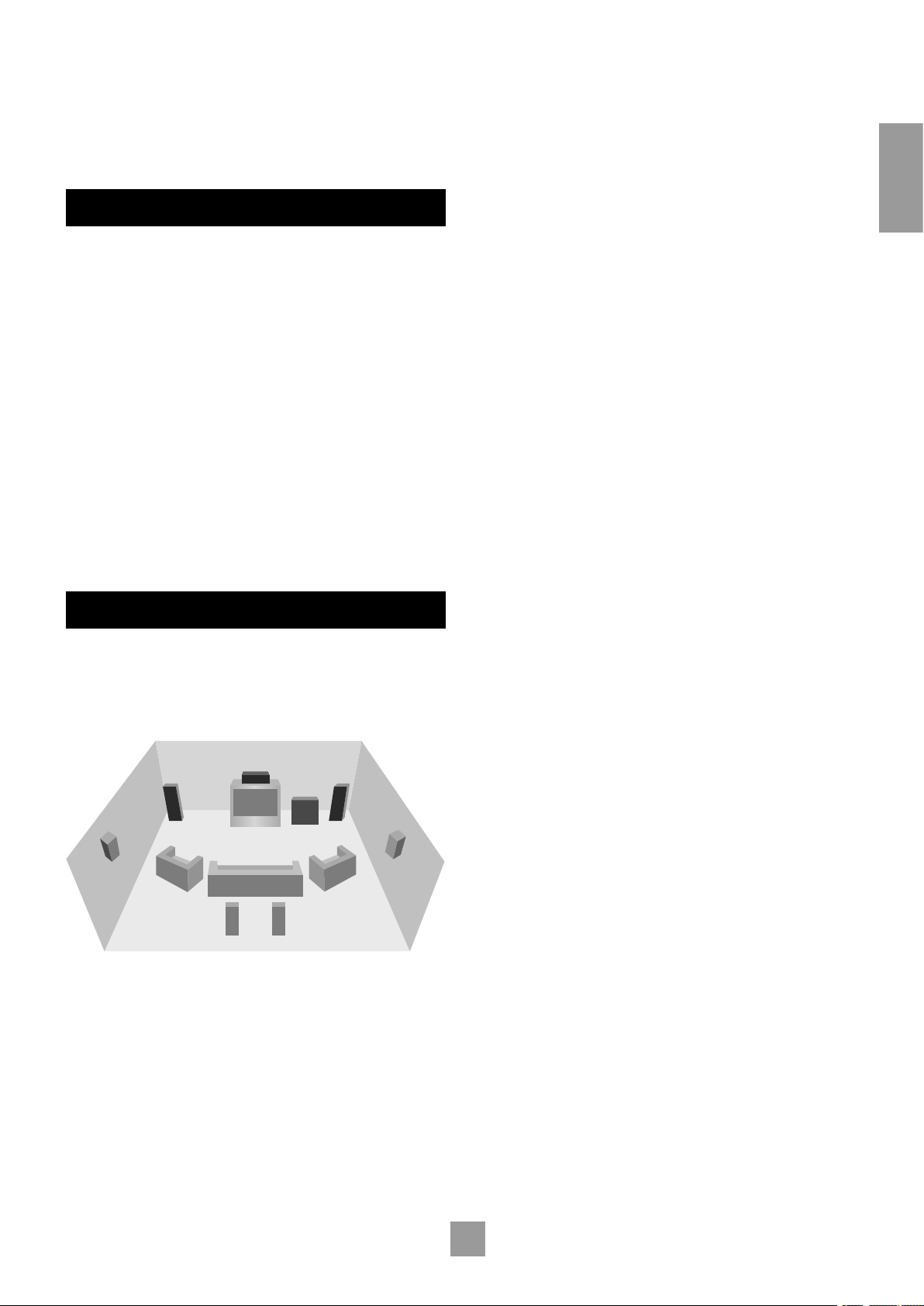
GENERAL
Surround
back left
Surround
back right
CentreFront
left
Front
right
Subwoofer
Surround
left
Surround
right
The inputs are named to make it easier to reference when connecting
e.g., a DVD or VCR, but they all have the same input circuit, so there
is no reason why you should not connect a different device to any of
the inputs. For example, if you had two DVD players and the AV input
was not being used, then the second DVD player can be connected to
the AV input.
CABLES
FRONT LEFT AND RIGHT
Position your front left and right speakers to achieve a good stereo
image for normal musical reproduction as well as for the multichannel
modes. If they are placed too close together there will be a lack of
spaciousness; if they are placed too far apart a stereo image will appear
to have a large ‘hole’ in the middle and will be presented in two halves.
If there is no practical alternative to placing the speakers widely apart,
this effect can be overcome in music reproduction by using centre
sound extraction from the left and right speakers (see Dolby ProLogic
II Music Mode).
English
We recommend the use of high quality screened analogue, digital and
video cables, as inferior quality cables will degrade the overall quality
of your system. Only use cables that are designed for the particular
application as other cables will have different impedance characteristics
that will degrade the performance of your system.
Video and digital connections must be made with cables that are
designed for this purpose, i.e., coaxial cable with a 75Ω impedance. If
substandard cables are used you may suffer from poor picture quality
such as ghost images and or grainy picture quality (snow).
Speaker cables should be kept short and low impedance wire should
be used throughout to ensure efficient power transmission and avoid
audible distortion.
All cables should be kept as short as is practically possible.
It is good practice when connecting your equipment to make sure that
the mains power supply cabling is kept as far away as possible from your
audio and video cables, as this will provide the best sound and picture
quality. Failure to do so may result in unwanted noise in the audio and
video signals.
SPEAKER INSTALLATION
The AV8 allows you to connect up to seven channels of amplification
and three active subwoofers in the main system. The output channels
correspond to speakers installed in the front left, centre, front right,
surround left, surround right, surround back left, surround back right
and an active subwoofer (see diagram).
CENTRE
The centre speaker allows for a more realistic reproduction of dialogue
and centre sounds. The centre speaker should have a similar tonal
balance to the front left and right speakers and be positioned at a
similar height.
SURROUND LEFT AND RIGHT
The surround left and right speakers reproduce the ambient sound and
effects present in a multichannel home cinema system and should be
installed approximately one metre higher than the listener’s ears.
SURROUND BACK LEFT AND RIGHT
The surround back left and right speakers are used to add extra depth
and better sound localisation and should be installed approximately
one metre higher than the listener’s ears. Place the two surround
back speakers such that there is an arc of approximately 150 degrees
between each surround back speaker and the centre speaker. The
surround back speakers should face the front of the room as shown
in the diagram to provide the largest ‘sweet spot’. You will then need
to measure the distance between the two surround back speakers
and set the ‘Advanced Speaker Array’ line of the ‘THX Settings’ menu
accordingly.
SUBWOOFER
A subwoofer will greatly improve the bass performance of your system.
This is useful for reproducing special cinema effects, especially where
a dedicated LFE (Low-Frequency Effects) channel is available, as with
many Dolby Digital or DTS encoded discs.
Multiple subwoofers may be required for larger installations, particularly
in rooms of a timber frame construction. Multiple subwoofers need
care in placement because there may be cancellation effects between
the units. Seek expert advice on multiple subwoofer placement.
GENERAL
All speakers, with the exception of the subwoofer, should be arranged
around your normal viewing/listening position (see diagram). The
subwoofer can be placed almost anywhere and we recommend
experimenting with it in various positions to obtain the best result.
The configuration and placement of your speakers are very important.
For THX surround EX playback we recommend that you use a THX
speaker system that is certified by Lucasfilm Ltd. If you are not installing
a full THX surround EX system then ignore the instructions regarding
the surround back left and right loudspeakers.
E-5
Page 6

E-7
English
bs bt ck clcm
OUT TUNER CD VCR
SA
T
TAPE
AV
DVD
bp bq br
DIGITAL INPUTS
LEFT
RIGHT
CENTRE
SUB
L SURR
R SURR RS
BACK
co cq cs dk
cn cp cr ct
DVD-A/SACD IN
LS
BACK
AUDIO CONNECTIONS
AUX/
PHONO
MM
MC
TUNER AV SAT DVDCD OUT IN
TAPE VCR
IN
AUDIO
L
R
OUT
6 8 9 bk bl bm
bn
bo
543 7
GND
Take care to place the audio cables as far from any power supply cabling
as is practically possible to reduce hum and noise problems.
Connect the analogue outputs from your source devices such as a
DVD player to the analogue inputs as shown:
ANALOGUE AUDIO INPUTS
TUNER, 4 CD, 6 TAPE 1N, 8 VCR IN, 9 AV, bk SAT,
3
DVD. Connect the left and right inputs to the left and right outputs
bl
of your source equipment.
AUX/PHONO. Unless the optional phono card has been installed,
bm
this input will function identically to the other line inputs. For example
it can be connected to a second CD player.
With the optional phono card installed this input can be connected
directly to a record deck. This card is available from your Arcam dealer
and caters for both moving magnet and moving coil cartridges.
MM/MC Switch. The switch on the back panel marked MM/MC is
bn
used to select the correct sensitivity to match the cartridge fitted to
the record deck, which is either moving magnet (MM) or moving coil
(MC).
If you are unsure which type of cartridge is fitted to your record deck,
connect the record deck and select the ‘MM’ setting on the switch. If,
when tested, the output from the record deck is very quiet compared
with the CD or DVD inputs then your cartridge is probably a moving
coil type cartridge. Turn the AV8 off and select the ‘MC’ setting on the
switch and test the record deck again.
Please note that if the AV8 is set to ‘MM’ and the record deck has a
‘MC’ cartridge fitted, testing these together will not cause any damage
to either the AV8 or the record deck.
DIGITAL AUDIO INPUTS
DVD, bq AV, br TAPE, bs TUNER, bt CD, ck VCR, cl SAT.
bp
Connect these inputs to the digital ouputs of your available source
equipment.
Notes:
Each of these seven digital inputs can be individually allocated to
different audio inputs if required, by use of the ‘Digital Settings’
page of the Setup menu.
The AV8 does not contain an RF decoder for Laserdisc with RF
output.
DIGITAL OUTPUT
(Digital) OUT. Connect this coaxial digital output to your digital
cm
recording device such as a CD-R, digital VCR or minidisc player.
When a digital source is selected, the digital output will send an exact
copy of the incoming digital signal. For example, for a 5.1 digital source,
the digital output will also be in 5.1 format.
On selecting an analogue source, the digital output will send an SPDIF
format digital signal, encoded with the analogue source material, with
one exception: if Neo:6 Cinema or Music mode is selected, the digital
output will be muted due to the extra processing required for these
modes.
MULTICHANNEL DVD-A/SACD INPUTS
The multichannel input is suitable for use with sources that decode the
surround channels internally, such as DVD-A or SACD players.
The AV8 switches these analogue inputs directly to the analogue
outputs via its own volume control circuit. This direct path maintains
the best possible sound quality for DVD-A and SACD sources.
GND. This is the phono earth or ground terminal and is used to
bo
connect to a turntable earth lead (if fitted). Note that this terminal must
not be used as a safety (mains) earth.
ANALOGUE RECORD OUTPUTS
TAPE OUT, 7 VCR OUT. Connect the left and right audio
5
outputs sockets to the left and right input sockets of your cassette deck
or VCR (usually labelled ‘RECORD’). The VCR connections may also be
used for a second tape deck.
LEFT, co RIGHT, cp CENTRE, cq SUB, cr L SURR, cs R SURR.
cn
Connect these input sockets to the equivalent audio outputs of your
DVD-Audio or SACD player.
LS BACK, and dk RS BACK. These are available for formats
ct
requiring eight channels. Currently no formats are available requiring
these connections, which are provided for future compatibility.
E-6
E-6
Page 7

ANALOGUE PREAMPLIFIER OUTPUTS
LEFT CENTRE L/SURR LS/BACKSUB/2
RIGHT SUB/1 R/SURR RS/BACKSUB/3
dm do dq ds ek
dl
dn
dp dr dt
OUTPUTS
ZONE 2
OUT
gp
gl gn
gm go
OUT
IN
LOCAL
12V
TRIGGER
IN
ZONE
2
REMOTE
ZONE 2
MONITOR OUT
2
1
gr
VIDEO
TRIGGERS
1/RGB 2/S-VIDEO
PROG
ZONE 2
AV SA
TMONITOR OUT DVD
VCR
OUT
2
1
TAPE
VIDEO
el em en eogr
eq er esep
fl fm fn fo fp fqetgs
VCR
IN
VIDEO
TRIGGERS
1/RGB 2/S-VIDEO
PROG
fk
gt
All these analogue outputs are buffered, have a low output impedance
and are at line level. They are able to drive long cables or several inputs
in parallel if required.
LEFT, dm RIGHT, dn CENTRE. Connect these to the equivalent
dl
front channel inputs of your power amplifier.
SUB 1. Main subwoofer output. Connect this to the input of your
do
active subwoofer, if you have one.
A receiver compatible with this connector is available from Xantech
(part no. 291-10). Please contact a Xantech registered dealer for this
part, as ARCAM do not stock them. See www.xantech.com for more
information.
The 3.5mm jack plug for this connector is wired as follows:
3.5mm stereo jack Function
Tip Signal
Ring 0V
Sleeve 12V, 30mA current-limited
This follows the Xantech standard for IR transmission over wire.
ZONE 2 Composite video connection. Connect to your zone 2
gr
video display using 75Ω low loss coaxial cable.
VIDEO CONNECTIONS
English
SUB 2, dq SUB 3. Subwoofer auxiliary outputs 2 and 3. These
dp
are equivalent to do and allow the use of multiple subwoofers. If
you are using more than one subwoofer, please set the number used
on the subwoofer setting page. Refer to ‘Basic and Advanced Set up’,
‘Subwoofer Settings’.
L SURR. Surround left output. Connect this output to the surround
dr
left power amplifier input.
R SURR. Surround right output. Connect this output to the
ds
surround right power amplifier input.
LS BACK, ek RS BACK Surround back left and right outputs (only
dt
used in 7.1 channel systems). Connect these outputs to the inputs of
your LS back and RS back amplifiers.
ZONE 2 CONNECTIONS
The AV8 allows independent routing and control of analogue audio
and composite video to a separate set of equipment, typically used for
a second living space, e.g., bedroom or lounge.
Zone 2 only outputs a signal from the analogue audio and composite
video inputs. The analogue inputs are required because there is no
analogue-to-digital, digital-to-analogue or DSP processing available for
zone 2 signals.
As the AV8 does not convert video formats a composite signal must
also be connected from the source.
For this reason we recommend that source devices that have a digital
connection are also connected to the analogue inputs. High quality
YUV/RGB and S-video sources should also have their composite
output connected to the AV8 for use in zone 2.
IMPORTANT NOTES
The AV8 has no video format conversion between component, RGB,
S-video or composite.
Wherever possible connect multiple video outputs from your video
sources. This enables use of the higher quality video connection for
the main system and the corresponding S-video and composite
connection for the record and zone 2 outputs.
For any video source to be viewed in zone 2 you must have a
composite video connection between the source and the AV8.
COMPOSITE VIDEO CONNECTIONS
MONITOR OUT 1. Connect this output to the composite video
el
input of your display device. (You will need an RCA phono-to-phono,
or, in Europe, a phono-to-SCART video cable to do this.)
MONITOR OUT 2. This is the same as el MONITOR OUT 1, and
em
enables a second display device to be used; it can also be used as a sync
reference for a four-wire RGB signal.
VCR IN, eq AV, er SAT, es DVD. Connect these inputs to the
ep
composite video outputs of your source equipment.
ZONE 2 OUT. Connect these to a line level input on your zone
gp
2 amplifier.
IN ZONE 2. This allows the AV8 to be controlled remotely from
go
zone 2 via infrared remote control.
VCR OUT. Connect to the composite video input of your video
eo
recorder (you will need an RCA phono-to-phono or, in Europe, a
phono-to-SCART video cable to do this).
TAPE. If you are using the tape loop for a second VCR then connect
en
the composite video from the VCR to this input.
S-VIDEO CONNECTIONS
MONITOR OUT. Connect this to the S-video input of your display
et
device.
VCR IN, fo AV, fp SAT, fq DVD. Connect these inputs to the
fn
S- video outputs of your source equipment.
E-7
Page 8

E-9
English
VCR OUT. Connect this to the S-video input of your video
Y/G U/B V/R Y/G V/R
1
2
V/R Y/G U/B V/R
OUT
3
fr
U/BY/G
U/B
fs
ftgk
HIGH QUALITY VIDEO
gl gn
gm go
OUT
IN
LOCAL
12V
TRIGGER
IN
ZONE
2
REMOTE
GROUND
LIFT (IN)
RS232
CONTROL
85 – 265VAC
MAX 40VA
gq
fm
recorder.
TAPE. If you are using the tape loop for a second VCR then connect
fl
the S-video from the VCR to this input.
HIGH QUALITY (COMPONENT) VIDEO
CONNECTIONS
These inputs are suitable for connection to component (YUV/ YCrCb)
or RGB outputs. These signals are usually available from a DVD player,
set-top box or games console and offer the best possible picture
quality.
Generally, the component video standard is used in North America/
NTSC regions, while RGB is used in Europe.
CONTROL CONNECTIONS
IN LOCAL. Use with a local IR receiver when the AV8 front panel
gn
IR receiver is obstructed.
IN ZONE 2. This allows the AV8 to be controlled remotely from
go
zone 2 via infrared remote control.
A receiver compatible with this connector is available from Xantech
(part no. 291-10). Please contact a Xantech registered dealer for this
part, as ARCAM do not stock them. See www.xantech.com for more
information.
The 3.5mm jack plug for this connector is wired as follows:
VIDEO 1, fs VIDEO 2, ft VIDEO 3 INPUTS. Connect these to
fr
the video outputs of your high quality video sources.
HIGH QUALITY VIDEO OUT. Connect these sockets to the
gk
component video inputs of your display device.
Important notes about HQ video inputs and outputs
When you connect your devices to these connectors, take care to
follow the letter/colour coding for each input. No damage will occur if
incorrectly connected, but unusually coloured or unstable pictures will
result.
In the ‘Video Settings’ setup menu, each of these three high quality
component video inputs can be individually allocated to one of the
following inputs: DVD, SAT, TUNER, TAPE, CD, VCR or AV.
You cannot mix component and RGB sources.
The high quality component video inputs have sufficient bandwidth for
line-doubled NTSC (525/60) or PAL (625/50) video and US HDTV
video signals. However, when used with such signals the OSD is not
overlaid on the picture but is output at standard interlaced NTSC or
PAL (525 or 625 line) rate on a solid background.
Initially, the high quality video inputs are all disabled. Before any HQ
video input can be selected it must be allocated to an input.
RGB 4-wire connection
Some video projectors and most European TV sets require the use of
a 4-wire RGB connection, where the ‘sync’ signal is separate from RGB.
In this case, you need to use the composite video MONITOR OUT 2
for the sync information. A special cable is available from your dealer
for 4-wire RGB connection (refer to the table of SCART connections
at the back of the manual).
3.5mm stereo jack Function
Tip Signal
Ring 0V
Sleeve 12V, 30mA current-limited
This follows the Xantech standard for IR transmission over wire.
Connect to a remote IR receiver in zone 2 to allow control of the AV8
from zone 2.
(REMOTE) OUT. This enables control of the source components
gl
remotely from zone 2 or zone 1 using the local input. Control is
possible by either connecting to the source devices via the 3.5mm IR
jack (Arcam units only) or using an IR emitter stuck to the centre of
the IR sensor window on the source component (such as a Xantech
283MW mini emitter).
RS232 CONTROL Use with control devices having an RS232 serial
gq
port (for example, Crestron and AMX touch screen controllers). This
connection is also used for upgrading control software. See the sections
at the end of this manual for control and programming information.
TRIGGER OUTPUTS
There are three trigger output sockets on the AV8, each of which is a
3.5mm stereo jack with two contacts, ‘tip’ and ‘ring’. See the tables for
technical information on the trigger outputs.
12V TRIGGER. Use for remotely turning on and off power amps or
gm
source equipment for the main zone and zone 2.
3.5mm stereo jack Function Voltage
Tip Main zone on On = 12V, 30mA
Off = 0V
Ring Zone 2 on On = 12V, 30mA
Off = 0V
Sleeve Ground 0V
E-8
E-8
Page 9

VIDEO TRIGGER 1, gt VIDEO TRIGGER 2. The trigger outputs
ZONE 2
MONITOR OUT
2
1
VIDEO
TRIGGERS
1/RGB 2/S-VIDEO
PROG
gs
gt
GROUND
LIFT (IN)
RS232
CONTROL
85 – 265VAC
MAX 40VA
1
2
gs
have different functions depending on how the ‘Video Status’ has been
set (Screen Ctrl or SCART) in the ‘General Settings’ menu.
SCART mode
1/RGB trigger output – connect to RGB SCART on your TV:
Connection Function Voltage
Tip RGB mode select RGB video = 1V (into 75Ω load)
Composite video = 0V
Ring RGB/composite
SCART input select
(CVBS status)
Aspect ratio 4:3/16:9
Sleeve Ground 0V
Video present, aspect 4:3 = 12V
Video present, aspect 16:9 = 6V
No video signal = 0V
2/S-video output – connect to S-video SCART (usually SCART no.
2) on your TV:
2/S-video output:
Connection Function Voltage
Tip Video source
trigger *
Ring Video source
trigger *
Sleeve Ground 0V
Any video source selected = 12V
No video source selected = 0V
Any video source selected = 12V
No video source selected = 0V
* Video source trigger – This output goes high when any video source
in the main zone is selected. It can be used to initiate closing of curtains
or dimming lights automatically.
Notes on Screen Ctrl mode
In Screen Ctrl mode, the video triggers behave differently. Both
outputs of video trigger 1 double up the role of the 12V trigger
output described earlier. They can be used to remotely switch on or off
additional equipment such as power amplifiers.
CONNECTING TO A POWER SUPPLY
Power inlet. The AV8 has a universal input power supply that is
1
compatible with mains voltages between 85VAC and 265VAC.
English
Connection Function Voltage
Tip Video source
trigger*
Ring S-video SCART
input select (CVBS
status)
Aspect ratio 4:3/16:9
Sleeve Ground 0V
Any video source selected = 12V
No video source selected = 0V
S-video present, aspect 4:3 = 12V
S-video present, aspect 16:9 = 6V
No video signal = 0V
Notes on SCART mode
In SCART mode, seamless selection of composite, S-video and RGB
A/V TV inputs is possible using the AV8.
When switched to a video source input, and the AV8 detects the
presence of either an S-video or composite video signal, it sets either
the S-video or the composite SCART input select lines high. If both
signal types are detected on that source input, then only the S-video
SCART input select line is set high.
If a high quality video source in RGB+Composite Syncs mode is
allocated to an input, the AV8 will assume an RGB signal is present
when syncs are detected on the composite input. In this case if only a
composite video signal is present on the input the AV8 will detect this
as an RGB+Composite Sync signal and display a blank screen, not the
composite video signal.
Information on SCART wiring is provided in the back of this manual.
NOTE: When the ‘HQ Video’ line of the ‘General Settings’ page is set
to ‘Component’ (rather than ‘RGB’), video trigger 1 behaves as listed
in the table for Screen Ctrl mode.
Screen Ctrl mode
1/RGB trigger output:
Connection Function Voltage
Tip Main zone on trigger Main zone turned on = 12V
Main zone turned off = 0V
Ring Main zone on trigger Main zone turned on = 12V
Main zone turned off = 0V
Sleeve Ground 0V
GROUND LIFT (IN) button. In complex setups which involve satellite
2
inputs or radio aerials, grounding the unit may increase the level of
background hum or buzz in the loudspeakers, in which case press the
GROUND LIFT button in to lift the signal ground from the chassis ground.
DO NOT REMOVE the safety earth from the mains cable under any
circumstances.
WRONG PLUG?
Check that the plug supplied with the unit fits your supply. If your
mains plug is different, consult your Arcam dealer or Arcam Customer
Support on +44 (0)1223 203200.
MAINS LEAD
The appliance is normally supplied with a moulded mains plug already
fitted to the lead. If for any reason the plug needs to be removed, it
must be disposed of immediately and securely, as it is a potential shock
hazard when inserted into the mains socket. Should you require a new
mains lead, contact your Arcam dealer.
PLUGGING IN
Push the plug (IEC line socket) of the power cable supplied with the
unit into the power input socket (1) in the back of the unit. Make sure
it is pushed in firmly.
Put the plug on the other end of the cable into your power supply
socket and switch the socket on.
E-9
Page 10

E-11
English
Setup Menu Index
Basic Advanced
1.General 1.Speaker EQ
2.Speaker Size 2.Video
3.Delays 3.Digital
4.Level Set 4.Zone 2
5.Sub Woofer 5.Input Trim
6.THX
Save Setup Exit Setup
Conguring the AV8
The AV8 ‘Setup Menu’ has six ‘Basic’ and five ‘Advanced’ menu screens
which take you through the configuration process. The ‘Basic’ menus
enable you to match your AV8 to your speakers. The ‘Advanced’ menus
allow you to optimise the operation of your system. Screen shots of
these menus are shown in shaded boxes on the following pages.
The best way to set up the AV8 is using the on-screen display (OSD).
To view the OSD for the initial set up, use the composite video output
because the high quality video output has several display modes, and
may be incompatible with your high quality display device in its default
configuration.
The AV8 defaults to the NTSC video standard – most display devices
can sync to this automatically. For PAL-only display devices, press and
hold the OK button for two seconds, when the AV8 will change to the
PAL video standard. As soon as a video signal is input to the AV8, it
automatically detects which standard it is and switches to it.
ENTERING SETUP MODE
To enter the Setup menus press and hold the MENU button on the
remote control, or on the front panel, for at least two seconds. The
‘Setup Menu Index’ is displayed on your display device.
Unstable OSD menu display?
Your AV8 may be in the wrong video standard mode. Press and hold
the OK button for more than two seconds to switch between the
NTSC and PAL standard OSD mode.
SETUP LOCK
To prevent tampering with the AV8 setup configuration you can ‘lock’
the menus by pressing the OK, TUNER and DVD-A buttons simultaneously
on the front panel. To unlock the AV8, press the same buttons again.
SETUP MENU
The main ‘Setup Menu’ page allows you instant access to six ‘Basic’ and
five ‘Advanced’ menus.
NAVIGATING USING THE REMOTE CONTROL
There are two ways to navigate through the Setup menus using the
remote control. The first method is for use when setting up the AV8
for the first time and allows you to progress methodically through the
menus:
1. Press and hold the MENU button (which is located immediately
under the navigation buttons) for two seconds to access the
‘Setup Menu Index’.
NOTE: Just briefly pressing the menu button takes you to
‘Main Menu Screen1’.
2. Navigate between menus using the
must be highlighted).
3. Navigate up and down the menu lines using the
4. Cycle through the options and select the required setting using
the
Return to the title bar and repeat sequences 2 to 4, working through
the six ‘Basic’ menus and the five ‘Advanced’ menus as required.
5. Press the MENU button to return to the main Setup menu
screen.
6. Press the OK button twice to select ‘Save Setup’ and save the
settings. This takes about four seconds. Then press OK twice again
to return to the Index, then exit the Setup menu.
A second method can be used when you need to make adjustments
to a specific menu screen:
1. Press and hold the MENU button for two seconds to access the
‘Setup Menu Index’.
2. Navigate up and down the ‘Setup Menu Index’ using56,
pressing OK to go to the selected menu option.
3. Use
4. Use
setting.
5. Press MENU to return to the main setup menu screen.
6. Press the OK button twice to select ‘Save Setup’ and save the
settings. This takes about four seconds. Then press OK twice again
to return to the Index, then exit the Setup menu.
NOTE: It is always possible to navigate between menus using the title
bar at the top of each menu page.
keys.
34
to navigate up and down the menu lines.
56
to cycle through the options and select the required
34
keys (the menu heading
34
56
keys.
They are listed side-by-side on the OSD on your display device. The
selected line of the menu is also displayed on the front panel of the
AV8. Use the remote control navigation button4to go to page 1 from
the menu heading, or use the navigation buttons to scroll down the list
to a specific page, then press OK to go directly to the page.
Save Setup takes you to the ‘Save Settings’ screen to allow you to
save in one of the five available presets.
Exit Setup exits the Setup menus without saving any changes.
Each of the following sections shows the screen that is displayed as you
move through the menus.
E-10
NAVIGATING USING THE FRONT PANEL
The AV8 front panel controls can be used to configure the options.
Please note that it is easier to configure using the remote control.
1. Press and hold the MENU button for two seconds to access the
Setup menu.
2. Navigate up and down the ‘Setup Menu Index’ menu using56,
pressing OK to go to the selected menu option.
3. Use
4. Use
setting.
Return to the title bar and repeat sequences 2 to 4, working through
the six ‘Basic’ menus and the five ‘Advanced’ menus as required.
5. Press MENU to return to the main setup menu screen.
6. Press the OK button twice to select ‘Save Setup’ and save the
settings. This takes about four seconds. Then press OK twice again
to return to the Index, then exit the Setup menu.
E-10
to navigate up and down the menu lines.
56
to cycle through the options and select the required
34
Page 11

BASIC SETUP
1 - General Settings
Volume Display: Normal 0-72
Max Volume: +72
Max On Volume: +20
Delay units: Imperial
OSD Mode: Mixed
Video Status: SCART
HQ Video: RGB
Sync On Green: Off
2 - Speaker Sizes
Auto Setup: Custom
Front L/R: Small
Centre: Small
Surr.L/R: Small
Surr.Back L/R: Small
Subwoofer: Present
Rears for 5.1: Both
1 – GENERAL SETTINGS:
Volume display: Allows you to select how volume is displayed.
Choose from Normal 0–72 (in 1dB steps), THX Ref –53dB to +18dB,
and Fine 0–72 (in 0.5dB steps). We recommend setting this to THX
Ref as this represents a volume control around 0dB (the reference
level) which is the same loudness level of a movie in a movie theatre
once you have correctly calibrated your system.
Max Volume: Limits the maximum volume setting the system can be
turned up to. This is a useful feature to prevent accidental overdriving
of low power-handling speakers, for example.
Max On Volume: Limits the maximum volume the system operates
at when it is first switched on. The system comes on at this volume if
the last used (possibly very loud) volume exceeds this value.
Delay units: Controls whether the delay settings for the speakers
in surround modes are specified in terms of Time, Imperial or
Metric distances from the listening position. Either enter the time
delay to each channel if calculating the delay in milliseconds, or select
between Imperial or Metric measurements to calculate the time delay
automatically. Imperial is measured in feet and Metric is measured more
precisely in 0.1m (10cm) increments. Note that 1 foot is approximately
0.3 metres.
NOTE: Changing the units resets all distances/times to zero. It is
therefore important to choose the units (Time, Imperial or Metric)
before set up.
OSD Mode: Controls how the on screen display is viewed. Mixed
will overlap the OSD on top of the existing video picture, while Full
Page will give a full screen black background with the OSD displayed
in white.
NOTE: In Mixed mode, the highlight bar is black if video is present. It
is blue if no video signal is present or if in Full Page mode.
Video Status: Can be set to Screen Ctrl or SCART. This controls the
triggers (Video Trig 1) into the display device to tell the display what
video type is being used. SCART refers to the multipole A/V connector
commonly used on European A/V equipment.
HQ Video: Allows selection of the high quality video output to match
your display device. Choose between RGB or Component. The AV8
allows progressive scan and high definition TV (HDTV) signals to be
passed through the high quality component inputs to the high quality
output. Note that the OSD cannot overlay text at any rate other than
standard NTSC or PAL.
On video signals that have a sync rate of greater than the normal
interlaced rate (i.e., progressive scan, frame-scaled video, HDTV) the
OSD will automatically go into Full Page mode (black background) so
that the control menu can be accessed. Any pop-up displays (such as
the volume bar, source selection information, etc) will be switched off.
Sync On Green: This applies only if RGB video is used. On makes
the AV8 feed the video sync signal out with the green signal. Some
RGB-driven display devices require a sync signal on the green input
to lock on to the video signal coming in, while others need the video
synchronisation on a separate lead. Systems using SCART connections
will normally have a four-wire system (i.e., with sync on composite
[CVBS] video).
NOTE: The ‘Sync on Green’ menu option is not selectable when
‘Component’ is selected as the HQ video type.
2 – SPEAKER SIZES
The size and number of loudspeakers are defined on this page of the
OSD.
A note on speaker sizes
A Large speaker is one that is capable of handling a full range signal (i.e.,
20Hz–20kHz).
A Small speaker is one that is not capable of reproducing a deep bass
signal (i.e., below 100Hz), for example a satellite speaker.
None is used when there is no speaker connected to that channel.
Auto Setup: Allows the setting of ‘standard configurations’ as in the
table below:
Speaker Config 1 Config.2 Config.3 Custom THX THX
Front
L/R
Centre Small Small Small Sm/Lge/
Surr
L/R
Surr
Back
L/R
Subwoofer
5.1
Rears
Custom setting allows you to choose any combination of speakers to
suit your system. Note that the centre and rear speakers cannot be set
to large if the front speakers are set to small.
THX automatically sets the speaker selections to the specified
configuration for THX™ listening. This automatically sets the
surround back speakers to None‚ and all filters are set to 80Hz. This
configuration is not adjustable. Only select this if you are using a full set
of THX™certified speakers.
THX Surr.EX automatically sets the speaker selections for a THX™
Surround EX setup with a pair of surround speakers, a pair of surround
back speakers and all filters set to 80Hz. This configuration is not
adjustable. Only select this if you are using a full set of THX™ certified
speakers.
E-11
Small Large Large Sm/Lge Small
THX
Small
None
Small Small Large Sm/Lge/
None
Small Small Small Sm/None None Small
Present None Present Present/
None
Both Both Both SurrL/R/
Sur Back
L/R/Both
THX
Small
THX
Present
THX
Surr
L/R
English
Surr.Ex
Small
THX
Small
THX
Small
THX
THX
Present
THX
Both
Page 12

E-13
English
5.1 Rear speakers defines how the speakers in a full ‘7.1’ installation
3 - Delay Settings
Front Left: 3Ft
Centre: 3Ft
Front Right: 3Ft
Surr. Left: 3Ft
Surr. Back L/R 3Ft
Surr. Right: 3Ft
Subwoofer: 3Ft
Fr
ont
left
Surr
left
Surr
right
Surr
back
left
Sub
woofer
Fr
ont
right
Centre
e.g. 3m
(9ft)
e.g. 4m
(12ft)
e.g. 2m
(6ft)
Surr
back
left
Surr
back
right
4 - Level Settings
Test Tone Cycle: Manual
Front L: ---I--- +0dB
Centre: ---I--- +0dB
Front R: ---I--- +0dB
Surr. R: ---I--- +0dB
Surr. BR: Not Present
Surr. BL: Not Present
Surr. L: ---I--- +0dB
Subwoofer: ---I--- +0dB
Select Speaker for Tone
5 - Subwoofer Settings
Crossover Freq.: 80Hz THX
Stereo Mode: Sat+Sub
LFE Level: ---I--- -0dB
DTS LFE Gain: 0dB Normal
Sub Stereo: ---I--- -0dB
DVD-A Sub Level: Normal
No. of Subwoofers: 1
handle 5.1 decoded sources.
Surr L/R redirects 5.1 surround signal to the surround left and
right speakers. No signal will be directed to the surround back
left or right speakers.
Surr Back L/R redirects 5.1 surround signal to the surround back
left and right speakers. No signal will be directed to the surround
left or right speakers.
Both redirects the 5.1 surround signal to both pairs of speakers
with the signal to each set reduced by 3dB.
4 – LEVEL SETTINGS
3 – SPEAKER DELAY SETTINGS
NOTE: Only enter these delay settings once you have specified what
delay units (i.e., Time, Imperial or Metric) you will be using, or the
information will be lost when changing units. If the delay units are set
to Time, then enter the delay in milliseconds for each channel.
The speaker distance control automatically sets the appropriate time
delays required for all the speakers in your system. To set up the correct
speaker distance, you must measure from the usual listening position to
the front of each individual speaker in the system. The delay adjustment
is not a substitute for proper speaker placement – it helps to ensure
accurate and correct signal arrival times from all the channels to the
primary listening position.
No measurement can be entered for a speaker that is not selected in
the previous ‘Speaker Sizes’ menu.
It is very important to calibrate the speakers correctly to achieve an
accurately centred sound stage. We recommend you use a sound
pressure level meter (SPL meter) to perform this part of the setup as
it is difficult to judge the levels accurately by ear alone.
Manual is best for setting up with an SPL meter as the test tone will
not change to the next speaker until instructed by you. Auto is best for
setting up by ear as the test tone changes automatically to each speaker
after a two second burst of sound.
On first installation, watch the OSD display as you cycle through the
available speakers with the test tone. Check that the speaker in use
corresponds to that indicated on the OSD. If there is an error then
check and correct the system cabling before proceeding further.
To calibrate the speakers with an SPL meter, place the meter at ear
level with the microphone pointing towards the ceiling, when seated in
the usual listening position. You will need to set the meter to ‘C’‚ setting
with a ‘slow’‚ response and to read 75dB SPL at the centre of the scale.
This volume is equivalent to normal conversation.
Each speaker can be finely tuned by 1dB increments to ±10dB. The
output from each speaker needs to be adjusted to the 75dB SPL sound
level. No adjustments can be made for a speaker that is not selected in
the previous ‘Speaker Sizes’ menu.
NOTE: If you do not have an SPL meter, simply set the front left
speaker to 0dB on the menu and then match all the other speakers
to this level.
Distance measurements for 5.1 [and 7.1]
speaker delay settings
E-12
5 – SUBWOOFER SETTINGS
If no subwoofer was selected in the previous speaker menus you
cannot adjust the stereo sub level or the number of subwoofers.
Crossover Frequency: Allows you to set the frequency at which
the signal is redirected from small speakers to the subwoofer or large
speakers. The adjustment can be made in increments of 10Hz between
40Hz and 150Hz.
If THX or THX Surr.EX have been selected in the previous menus, the
crossover frequency will be set to THX specification at 80Hz.
Stereo Mode: Select between Large, Large+Sub or Sat+Sub. You
have the flexibility to choose how bass information is distributed to
your speakers only if you have large front left and right speakers and
a subwoofer as part of your home theatre speaker system. To decide
which setting is best for your room, once you have positioned all of
your speakers, choose the option which gives you the most solid even
sounding bass using a setup disc or live program material.
Large Pure stereo information. Use this setting if you have large
front speakers.
E-12
Page 13

Large+Sub Pure stereo fed to left and right and extracted bass is
6 - THX Settings
THX Surr. EX: Auto
Boundary Gain Compensation
THX Ultra 2 Sub: No
Advanced Speaker Array
SurrBack L/R: 12 to 48in
6 - THX Settings
THX Surr. EX: Auto
Boundary Gain Compensation
THX Ultra 2 Sub: Yes
Boundary Gain Comp: On
Advanced Speaker Array
SurrBack L/R: 12 to 48in
Surr
left
Surr
right
Surr
back
left
Surr
back
left
Surr
back
right
sent to the subwoofer.
Sat+Sub Use this setting if you have ‘Small’ satellite left and right
speakers. Full bass management is used in analogue stereo so
that analogue sources are fed to the DSP where the bass is
filtered off left and right and redirected to the subwoofer.
NOTE: The above three Stereo Mode settings pass the audio
through the DSP. The Large setting can be duplicated for analogue
inputs by pressing Direct to bypass the DSP.
LFE Level: Allows you to adjust the output level of the low frequency
effects channel relative to the other speakers in the system. This
adjustment affects the loudness of movie low frequency effects such as
thunder, explosions, etc.
DTS LFE Gain: DTS soundtracks typically have the LFE track recorded
10dB lower than the main audio tracks. It is therefore necessary to
compensate for this by raising the LFE output level by 10dB. Setting the
DTS LFE gain to Normal activates this compensation.
Some DTS soundtracks have been recorded with the LFE signal at
the same levels as the main audio and therefore require no gain
compensation. For these disks set the DTS LFE gain to -10dB.
Sub Stereo: Allows you to trim the subwoofer output for stereo
listening. Use this trim setting, with a stereo source, to reduce the
subwoofer output in stereo playback to an acceptable level. The
subwoofer level for stereo music often needs to be set at a lower
level than that for cinema use. This depends on various factors such as
speakers, the types and styles of music to be played and personal taste.
DVD-A Sub Level: External decoder sub level outputs are typically
the same level as the main audio and therefore require no gain
compensation. For these decoders set the DVD-A sub level to Normal,
the default setting.
Some external decoders may have the sub output 10dB lower than the
main audio outputs. It is therefore necessary to compensate for this by
raising the sub level by 10dB. Setting the DVD-A sub level to +10dB
activates this compensation.
No. of subwoofers: Allows you to set the number of subwoofers
used in the system from 1 to 3. All three subwoofer outputs are active
all the time. This setting compensates the sub output level for the
number of subwoofers in the system.
6 – THX SETTINGS
Manual The AV8 will not select THX Surr. EX automatically. It
can however be selected manually by pressing the THX button.
Boundary Gain Compensation
THX Ultra2 Sub: THX Ultra2 specified subwoofers can effectively
deliver down to 20Hz, which may be problematic in some rooms.
Set to No if the subwoofer being used is not a THX Ultra2 specified
subwoofer, or is not capable of a good response to 20Hz.
Set to Yes If you are using a 20Hz subwoofer or a THX Ultra2
specified subwoofer. When set to Yes, another menu option
appears.
Boundary Gain Compensation: Tailors the subwoofer low
frequency response.
When set to On, this will roll off the very low frequency
information coming from the subwoofer so that any interactions
and reinforcements from nearby boundaries (i.e., walls) can be
compensated for to reduce boom and overblown bass response.
We recommend this setting for smaller rooms.
When set to Off, the subwoofer output from the AV8 will
remain flat to 20Hz.
Advanced Speaker Array: Set this distance to be the separation
between the surround back left and right speakers. This enables the AV8
to distribute the signal to the surround back speakers appropriately to
get the most accurate image for the soundstage.
Measurement units are in inches only, 30cm = 12 inches.
SAVING SETTINGS AND EXIT SETUP
You can either save the settings now and exit or continue to the
‘Advanced Setup’ instructions.
Save Setup
1. Press MENU to go to the ‘Setup Menu Index’ at the ‘Save Setup’
point.
2. Press OK to go to the ‘Save Settings’ menu.
3. Press
setting.
4. Press OK twice to save and exit to ‘Setup Menu Index’.
5. After the AV8 has finished saving, press OK to return to the
‘Setup Menu Index’.
6. Press OK to select ‘Exit Setup’ and exit system configuration.
NOTE: It is possible to change the name of the presets – see the
‘Advanced Settings’ section for a more detailed explanation.
to select the desired ‘Preset’ to which to save the
56
English
THX Surr. EX: This can either be set to Auto or Manual and is only
applicable when playing THX Surr. EX encoded material.
Auto The AV8 automatically switches THX to THX Surr. EX when
suitably encoded material is detected (this can be temporarily
overridden by pressing the THX button on the AV8).
Exit without saving
If you choose to ‘Exit Setup’ without first saving the changes, then these
new settings will be used by the AV8 until you recall a preset or press
FAV on the remote control, when the last used preset will be recalled.
This is the case even if the AV8 is put into standby or turned off.
1. Press MENU to go to the ‘Setup Menu Index’ at the ‘Save Setup’
point.
2. Press4to select ‘Exit Setup’.
3. Press OK when ‘Exit Setup’ is selected to exit system
configuration.
E-13
Page 14

E-15
English
ADVANCED SETUP
Adv 1 - Speaker Eq.
Bass Treble
FL: --I-- +0dB --I-- +0dB
C: --I-- +0dB --I-- +0dB
FR: --I-- +0dB --I-- +0dB
SR: --I-- +0dB --I-- +0dB
SBR: --I-- +0dB --I-- +0dB
SBL: --I-- +0dB --I-- +0dB
SL: --I-- +0dB --I-- +0dB
Auto Stereo Tone Bypass: Yes
Adv 2 - Video Settings
OSD: On
Video Input Aux: None
Video Input CD: None
Video Input Tuner: None
Video Input DVD-A: None
Audio and Video: Tracked
HQ Vid 1 Comp/RGB: None
HQ Vid 2 Comp/RGB: None
HQ Vid 3 Comp/RGB: None
Adv 3 - Digital Settings
Coaxial Inputs
DVD input: DVD button
AV input: AV button
Tape input: Tape button
Tuner input: Tuner button
CD input: CD button
Optical Inputs
VCR input: VCR button
Sat input: Sat button
ADV 1 – SPEAKER EQ.
Allows advanced adjustment of all the speakers for bass and treble
management in 1dB steps up to ±6dB. The tone control nominal
corner frequencies are at 100Hz and 8kHz, shelf type. Use these
adjustments sparingly to compensate for speaker response problems
caused by positioning, adjacent surface textures, or mixed brands of
loudspeakers.
Work with one speaker on at a time, and as an example, use the bass
control to reduce boom problems for speakers placed in corners, and
the treble control for speakers placed near reflective surfaces.
We recommend trying to obtain a good speaker response by speaker
placement first, then apply speaker eq. last.
Auto Stereo Tone Bypass: Set to Yes if you wish to automatically
have any tone adjustments made in ‘Main Menu Screen 1’ by-passed in
analogue or digital mode.
NOTE: This does not switch the AV8 into Direct mode, only sets the
tone controls to zero.
ADV 2 – VIDEO SETTINGS
source at the same time – for example, you can listen to radio while
watching TV for a sports simulcast.
Audio and Video: Applies to the audio and video assignments set up
in the ‘Main Menu Screen 1’.
If set to Separate, then audio and video signals for video sources
can be separately assigned (e.g., DVD sound with video from
a satellite receiver). Once assigned separate, audio and video
remain separate.
If set to Tracked, audio and video signals are linked together
(e.g., DVD audio and video). This setting is recommended for
simplicity. In this mode, audio and video sources can still be
separated temporarily by using ‘Main Menu Screen 1’.
HQ Vid 1, 2 and 3: Allocates the high quality component or RGB
video inputs to any source buttons. For example, to use the component
or RGB output on a DVD player with HQ Vid 1 input, select DVD in
the menu.
ADV 3 – DIGITAL SETTINGS
Coaxial inputs and Optical inputs. Each of the digital inputs can
be assigned to any of the eight stereo source buttons (AUX, CD, TUNER,
TAPE, DVD, SAT, AV and VCR), or can be assigned No button.
The OSD menu lists the physical inputs, as per the back panel, on the
left hand side of the screen, and the buttons used to select the inputs
are listed on the right hand side.
Each digital input can only be allocated to one source button. For
example, if you choose the ‘Coaxial DVD input’ to be assigned to the
DVD button, then the choices for the other digital inputs are: Aux, CD,
Tuner, Tape, Sat, AV, VCR and No button. If you wish to re-allocate
the DVD input to a button that is already assigned to the ‘AV input’
(for example), ‘AV input’ must be assigned to a different button (or No
button) before you can re-assign this new button to ‘DVD input’.
This menu allows advanced adjustment of the video settings for your
AV8.
OSD: Selects whether the main zone OSD is on or off.
When set to On‚ all user adjustments that are made during the
general use of the AV8 are displayed on the screen. This includes
the adjustment of the volume control, the inputs selected and
the setup menus.
When set to Off‚ you will have no displays of the general user
adjustments – only the setup menus and the main menus are
displayed.
It is recommended you keep the OSD turned On‚ since if you cannot
see the front panel of the AV8 you will have no idea if any adjustments
you have made to the processor are correct or to your liking.
Video Inputs: Composite and S-video inputs for DVD, Sat, AV, VCR
and Tape have, by default, their audio and video assigned to track each
other. The four Video Input lines for Aux, CD, Tuner and DVD-A allow
you to assign a video source to these normally audio-only sources. You
can allocate the same video source to more than one audio input. This
facility allows you to listen to an audio source and view a separate video
E-14
E-14
Page 15

ADV 4 – ZONE 2 SETTINGS
Adv 4 - Zone 2 Settings
Max Vol 20-72: 72
Fix Vol: No
Max On Vol 0-72: 20
Zone 1 Standby: Local Only
Zone 2 Standby: Local Only
Local OSD: On
Zone 1 Control: Yes
Access: All
Adv 5 - Input Trims
Aux: Reference 2V
DVD: Reference 2V
Sat: Reference 2V
AV: Reference 2V
VCR: Reference 2V
Tape: Reference 2V
CD: Reference 2V
Tuner: Reference 2V
DVD-A: Reference 2V
ADV 5 – INPUT TRIMS
English
Max Vol 20–72: Limits the maximum volume setting for zone 2. This
is a useful feature to prevent accidental overdriving of low powerhandling speakers (for example).
Fix Vol: This selects between fixed and variable audio output to zone 2.
If No is selected, the output level can be controlled from zone 2 or the
main system. If you want to fix the volume level, first set the zone 2
volume to the desired level, then select Yes.
Max On Vol 0–72: Limits the maximum volume zone 2 operates at
when it is first switched on. Zone 2 comes on at this volume if the last
used (possibly very loud) volume exceeds this value.
Zone 1 Standby: This allows zone 1 (the main zone) to be put into
standby, either locally only or by zone 2 as well.
Local Only Only zone 1 will be switched into standby from
zone 1.
All Off Both zone 1 and zone 2 will be switched into standby
from zone 1.
NOTE: The setting for ‘Zone 1 Standby’ only applies for putting
the AV8 into standby mode. Re-activating zone 1 is always a local
function.
Zone 2 Standby: This allows zone 2 to be put into standby, either
locally only or by zone 1 as well.
Local Only Only zone 2 will be switched into standby from
zone 2.
All Off Both zone 1 and zone 2 can be switched into standby
from zone 2.
NOTE: The setting for ‘Zone 2 Standby’ only applies for putting
the AV8 into standby mode. Re-activating zone 2 is always a local
function.
Input trims: Allows the adjustment of the input sensitivity of the
analogue inputs (in Volts rms) so that each one achieves the optimum
dynamic range and sounds similar in loudness to each other.
Available level settings are; Low 1V, Reference 2V, Medium 4V, High 8V.
The reference level of 2V should be appropriate for most inputs.
To ensure the correct level is set up, first ensure that all source levels
are set to Reference 2V. Find some loud music or use a 0dB reference
signal from each source. If the source activates the ‘Analogue CLIP’
indication at the bottom of the screen, then adjust its level upwards
to 4V or 8V, until the ‘Analogue CLIP’ indicator is no longer there.
Then repeat the adjustment process with every other input, selecting
the lowest voltage setting that does not activate the ‘Analogue CLIP’
indicator. If in doubt or a loud signal is not available, then leave a
source on the 2V setting. If you have a CD player with built-in HDCD
decoding, you should generally use the 4V setting.
If a source is very quiet compared with the other sources you can
increase its loudness by selecting the Low 1V setting. Once set, we
suggest you play some loud music from this source to check the
‘Analogue CLIP’ indicator does not come on.
NOTE: The ‘Analogue CLIP’ detector is only active in the ‘Input Trims’
menu, and only responds to the input indicated by the highlight bar
on the screen.
When the Aux input is converted into a Phono (turntable) input, the
sensitivity adjustment is still available.
The ‘Input Trims’ control is only available for analogue inputs. Whenever
a digital input is selected, this control is overridden.
Local OSD: Selects whether the zone 2 OSD is on or off.
When set to On‚ all user adjustments that are made during the
use of zone 2 are displayed on the zone 2 video. This includes the
adjustment of the volume control, the inputs selected and the
setup menus. It is recommended that zone 2 OSD turned On‚
as there is no other display available in zone 2.
When set to Off, all user adjustment displays are disabled, but
pressing the MENU key still displays the zone 2 control menu.
Zone 1 Control: If set to Yes this allows zone 2 to control and adjust
inputs and user controls for the main zone.
Access: This acts as a ‘parental control’ device to disable or enable
access to sources for zone 2.
Press the unwanted source button on the remote control handset or
front panel to disable it for zone 2. Press again to enable the source.
Enabled sources are listed on the ‘Access:’ line of the OSD.
E-15
Page 16

E-17
English
SAVING SETTINGS AND EXITING SETUP
Save Settings
No Save - Return to index
Save as:Preset 1*
Preset 2
Preset 3
Preset 4
Preset 5
Press OK to edit- OK to save
All the settings you have made on the previous screens can be saved
as a user profile and stored as one of five ‘Presets’. A choice of setup
presets caters for different events such as movies or sport, and for
different user preferences.
To make these customised settings easier to retrieve, you can give each
preset a memorable name, such as ‘John’, ‘Jacky’, ‘Movies’, ‘Sport’, ‘Rock’,
etc.
The presets store the complete setup of the AV8, including the modes
used for each of the inputs and if they are in direct mode or not.
The presets can be used to create different listening preferences. You
may wish to set up different presets for listening to music, watching
DVD, watching TV material or for different listening positions.
To change the name of a preset, highlight it by using the
navigation5and6buttons. Press the OK button to edit. Using
the5and6navigation buttons, cycle through and select lower case
letters (a…z), upper case letters (A…Z) and numbers (0…9). Move
along the line using the3and4buttons.
When you are satisfied with the text you have written, press OK to save
the preset name and to store the setup parameters under this name.
IMPORTANT NOTE: Settings must be explicitly saved before the
unit is switched off, otherwise changes to the settings will be lost and
the unit will need to be set up again.
E-16
E-16
Page 17

Front panel controls
POWER
AV8 PRE AMP PROCES SOR
DVD ATAPEPHONO/AUXVCRAVSATDVD
MENUDISPLAY
CD TUNER
MO D E
EFFECTTHX
9 bn876
1
5
bo
OK
DIRECT MUTE
THX SU RROUND EX
432
bk
bl
bm
V o l : + 8
A n . P LI I
M o vi e
To ne
bp
English
Remote control receiver. This is positioned behind the FMJ
1
badge. Ensure the receiver is in a clear line of sight from the remote
control for operation. If this is not possible, use a separate sensor
connected to the IR input on the rear panel.
THX. Selects between the available THX® modes.
2
Effect. Selects between the available DSP effects modes for two-
3
channel sources. All other modes must be switched off first.
Mode. Selects between Stereo, Mono and the available surround
4
modes for the current source.
Phones. This socket accepts headphones with an impedance rating
5
between 32Ω and 600Ω, fitted with a 1/4-inch stereo jack plug.
Display. This switches the display brightness between Off/Dim/
6
Bright.
Menu. Selects the ‘Main Menu’ on the OSD. Also accesses the
7
‘Setup Menu Index’ when pressed for two seconds.
OK. Used to enter selections made from operating menus. Also
8
changes the OSD video standard (PAL/NTSC) when pressed for two
seconds.
Control knob. The control knob has two functions:
9
as a volume control, to adjust the output to the power
amplifier(s) and headphones connected to the AV8.
when used in the menus with the
button, to navigate menu options.
EFFECT button and5MODE
6
Source selectors. These buttons select the source connected to
bk
the corresponding input. A light above the relevant button indicates
which input is currently selected.
Direct. Stereo direct on/off. Provides a direct analogue path from
bl
analogue inputs to the left and right front outputs. Switches off any
sound processing modes and shuts down the DSP circuits for best
stereo sound quality.
Mute. Mutes all main analogue ouputs when selected.
bm
Power. Switches the main power to the AV8 on and off.
bn
NOTE: Once the unit is switched off, it should be left off for at least
ten seconds before switching on again.
Power/Standby LED. This indicates the status of the preamp
bo
processor. When first turned on, the LED is yellow, to indicate that the
AV8 is ‘initialising’. This changes to green when the AV8 is fully powered
and ready. Red indicates that the AV8 is in standby mode.
Tone Control Indicator. Indicates that bass or treble tone
bp
equalisation is currently active.
E-17
Page 18

E-19
English
Remote control
SELECT DEVICE
SET
LAST
SLEEP
A–B
EXIT
GUIDE
CH
VOL
MUTE
0
FM
8 AV 9 MCH7 TUN
5 AUX 6 TAPE4 CD
2
SAT
3
VCR
1
DVD
THX
FX
SUB
P.MODE SUBT TITLE MENU
ZOOM AUDIO MEM RETURN
ANGLE SETUP STATUS SEARCH
DIS TRM 1 2
TST SYN DYN SLP
P – P + TM FAV
MODE
OPEN
MENU
INFO
CR80
DVDCBL VCR TV
SAT CD AMP AUX
OK
AM
The CR80 remote control is a multi-function unit that controls the AV8
and up to seven other devices. The instructions on this page only refer
to the control of the Arcam FMJ AV8.
For information on using the remote control for other devices, and a
full list of features, see the instruction booklet supplied with the CR80.
Source selection
DVD – DVD input
SAT – Satellite input
VCR – Video Cassette Recorder input
CD – Compact Disc player input
AUX – Auxillary (line) input
TAPE – Tape (monitor) input
TUN – Tuner input
AV – AV input
MCH – DVD-A (multichannel) input
Press the relevant button once to select input; press
and hold to select the analogue input if a digital input
is present.
MUTE
Press once to mute the main system. Press again (or
use VOL +/–) to un-mute.
VOLUME +/–
Adjusts the volume.
MODE
Use this button to cycle through available surround
modes.
INFO
Press once to display the OSD report on source
inputs and processing mode.
SYN (Lip sync)
Press once to adjust the Lip sync audio delay. Use
the
Press again to exit the Lip sync function.
3
and
DIS (Display)
Press to cycle through Off/Dim/Bright illumination
of the front panel display
4
navigation buttons.
Device selection
IMPORTANT: Press the ‘AMP’ button first to
operate the AV8.
On/Standby
This allows the AV8 to be put into and taken out of
standby remotely.
THX (THX mode)
Use this button to cycle through available THX
modes.
FX (DSP effects mode)
Use this button to cycle through effects modes for
two-channel sources.
SUB (Subwoofer trim)
Allows a temporary trim of the subwoofer level.
Press SUB, then adjust using the
the navigation panel.
Navigation buttons
Arrow buttons allow navigation around the menus
on the AV8.
Confirm selection by pressing OK. Press and hold
the OK button to swap PAL/NTSC OSD modes.
MENU
Press to select the OSD Main menu.
Press and hold for more than two seconds to
select the ‘Setup Menu Index’.
FAV (Favourite)
Use this button to clear any temporary
adjustments and return to the current preset
settings.
The other buttons in this area are used for DVD
and Tuner control and do not effect the AV8.
34
buttons on
TRM (Speaker trim)
Press to display the OSD Speaker trim level menu.
TRM allows temporary adjustment of speaker
levels, using the navigation buttons. Press again to
exit the ‘Speaker Trim’ function.
E-18
E-18
NOTE
Remember to correctly install the two AA batteries supplied
before trying to use your remote control.
Page 19

V o l : + 8 A n . P L I I
M o vi e
To ne
Operating your AV8
INTRODUCTION
For information display we recommend you use the OSD on your
TV/screen whenever possible. However all key information is also
duplicated one line at a time on the front panel display of the AV8.
USING THE CONTROLS
SWITCHING ON
Press the power button in. Between one and five seconds later, the
power LED will then come on (first as yellow), the front panel display
window shows ‘ARCAM’, followed by ‘initialising’. This is followed by
the initial volume setting and the name of the input selected. After
initialisation is complete, the power LED changes colour to green.
Please wait until the unit has finished initialising before operating the
AV8. It is recommended that if the unit is switched off, you should wait
at least 10 seconds before switching the unit back on.
STANDBY
The AV8 has a standby mode which can be entered by pressing
STANDBY on the remote control. When in standby mode the display is
blank and the power LED glows red.
When not being used, the AV8 may be left in standby mode, as power
consumption is low. If you are not using your AV8 for several days we
recommend you switch the unit completely off at the front panel.
TO SWITCH ON FROM STANDBY
Press one of the source buttons on the front panel or on the remote
control, or use the standby button on the remote control.
FRONT PANEL DISPLAY
The AV8 is ready for use after about four seconds. This display window
shows the processing mode and initial volume setting.
Output channels in digital processing modes are indicated in the format:
‘3/2.1’, where ‘3’ refers to the front channels, ‘2’ to the rear channels,
and ‘.1’ to the subwoofer channel. Some variants of this format are
described below.
The processing mode and Stereo Direct functions are remembered
and recalled for each input. The digital input and high quality video
input associated with each source may be customised in the setup
procedure.
The DVD-A input is intended for direct analogue pass-through of DVD
Audio or SACD surround sources. Apart from volume control and
level trim, no processing modes are possible on this input.
TAPE OPERATION
The AV8 has a fully independent tape loop. This can be configured to
record the source you are listening to, or to record any other input
using the ‘Record to Tape’ option in ‘Main Menu Screen 2’.
Pressing the TAPE button will select audio from the tape input.
If the ‘Record to Tape’ option is set to Source (its default setting), the
tape LED will illuminate as well as the previously selected input.
If the ‘Record to Tape’ option is set to a specific input, the tape LED will
illuminate as well as the input selected in the ‘Record to Tape’ menu
item.
This indicates the tape loop is active and displays the source that will
be recorded.
For example, if ‘Record to Tape’ is set to Source and you want to record
the CD input:
Select the CD input then put your recorder into record pause so
that it will monitor its input.
Press the TAPE button – you can now listen to the sound actually
being recorded by your tape deck from the CD player.
If you select a different source from CD, the recording will
change to this source.
If you want to record from CD while listening to the Tuner input:
Call up the ‘Main Menu Screen 2’ and set ‘Record to Tape’ to
CD.
Put your recorder into record pause so that it monitors its input
then press the TAPE button. You can now start the recording and
listen to the sound actually being recorded by your tape deck
from the CD player.
Once the recording is running press the TUNER button to listen
to the Tuner, the recording of the CD will continue.
You can check the progress of the recording at any time by
pressing the TAPE button again.
English
Recorded
format
3/2/1 3 2 Yes Full 5.1 sound
3/2/0 3 2 No 5-channel sound, no LFE
3/0/0 3 No No 3-channel sound, no LFE
2/0/0 2 No No Stereo (Dolby digital or
Front
speakers
Surround
speakers
Subwoofer
Comment
DTS encoded)
SELECTING A SOURCE
To select a particular source, press the corresponding button on
the front panel or on the remote control. There are nine inputs
available: DVD, Sat, AV, VCR, Phono/Aux, CD, Tuner, Tape and DVD-A
(multichannel).
On selecting a source, the AV8 will normally select an active digital
input in preference to an analogue input. If you want to override the
digital input and select the analogue input, press and hold the source
button for at least two seconds.
VCR OPERATION
The AV8 has a fully independent VCR loop for audio and video
(Composite and S-video only). This can be configured to record the
source you are watching to or to record any other input using the
‘Record to VCR’ option in the ‘Main Menu Screen 2’.
Pressing the VCR button selects audio and video from the VCR
input.
If the ‘Record to VCR’ option is set to Source (its default setting),
the VCR LED illuminates as well as the previously selected
input.
If the ‘Record to VCR’ option is set to a specific input, the VCR
LED illuminates as well as the input selected in the VCR menu.
This indicates the VCR loop is active and displays the source that will
be recorded.
E-19
Page 20

E-21
English
For example, if ‘Record to VCR’ is set to Source and you want to record
the SAT input:
Select the SAT input then put your VCR into record pause so that
it will monitor its input.
Press the VCR button, and you can now watch the audio and
video actually being recorded by your VCR from the satellite
system.
If you select a different source from SAT, the recording changes
to this source.
If you want to record from SAT while watching the AV input:
Call up the ‘Main Menu Screen 2’ and set ‘Record to VCR’ to
SAT.
Put your VCR into record pause so that it monitors its input, then
press the VCR button.
You can now start the recording and watch the audio and video
actually being recorded by your VCR.
Once the recording is running, or you have set the timer on the
VCR, press the AV button to watch the AV input. The recording
of the SAT input continues or starts when the timer activates.
You can check the progress of the recording at any time by
pressing the VCR button again.
To listen to zone 2 using the headphones:
Call up ‘Main Menu Screen 1’ by pressing the MENU button.
Navigate to screen 3 of the Main Menu by pressing the
on the remote, or by turning the volume knob on the front
panel.
4
button
Move the highlighted line to ‘Headphone Out’.
Use the
select zone 2.
When listening to zone 2 via the headphones, you can control the
source and volume from ‘Main Menu Screen 3’.
To select a source:
button on the remote, or use the volume knob to
4
Move the highlighted line to ‘Zone 2 audio’.
Use the
To change the volume:
buttons to select the source you wish to hear.
34
Move the highlighted line to ‘Vol’.
Use the
NOTE: If the headphones are associated with zone 2, the main
volume control knob on the AV8 will not adjust the headphone
volume level as this only controls the main zone 1 volume setting.
buttons to move the volume up and down.
34
STEREO DIRECT
To listen to a pure analogue stereo input, press the DIRECT button. The
Direct mode automatically bypasses all processing and any surround
functions. In Direct mode, digital processing is shut down to improve
the sound quality and reduces digital noise within the AV8 to an
absolute minimum. The LED above the DIRECT button on the front
panel also lights to indicate this mode.
NOTE: When the digital processing is shut down, no digital output
is available.
VOLUME CONTROL
It is important to realise that the position of the volume control
indicator bar is not an accurate indication of the power delivered to
your loudspeakers. The AV8 often delivers its full output power long
before the volume control reaches its maximum position, particularly
when listening to heavily recorded music. In comparison, some movie
sountracks can appear to be very quiet, as many directors like to keep
the maximum levels in reserve for special effect sequences.
If your system is set up in THX reference configuration, the volume
range will cover –53dB to +18dB, where 0dB is the THX reference
level at which the movie director intended the movie to be reproduced.
If your room is small you may find this too loud, so reduce the level until
you are comfortable.
HEADPHONES
To use headphones with the AV8, plug the headphones into the socket
on the left hand side of the front panel.
When headphones are plugged into the headphones socket the
outputs for the zone to which they are assigned is muted. If that zone
is zone 1 and it is in a surround sound mode, the audio will be downmixed to two channels (2.0). The two-channel down-mix is required
so that the centre channel and surround information can be heard via
the headphones.
NOTE: If the headphones are selected to zone 2, only analogue
sources can be heard as there is no digital-to-analogue conversion
available for zone 2.
EFFECTS/FX
The EFFECTS button (FX on the remote) cycles through the available
effect modes. The effects are only available when the AV8 is in stereo
mode. The AV8 effects are:
Effect Description
None No effects active, stereo signal
Music Extracted ambience and centre information
Party All speakers on
Club Small room
Hall Medium reverberant room
Sport Very reverberant with extracted ambience and dry centre
dialogue
Church Long reverberant room
For more information on the effects, see the section ‘DSP Effects
Modes’.
THX
This button cycles through the available THX modes. The available THX
modes change depending on what mode the AV8 is in and what source
material is being played.
For more information on THX, see the section ‘THX Modes’ on page 26.
SUB
This button on the remote allows temporary trim of the Subwoofer
level. Press SUB, then adjust using the
pad.
buttons on the navigation
34
FAV
Use this button on the remote to clear any temporary adjustments and
return to the current or ‘favourite’ preset settings.
MUTE
Use this button to mute the local zone. Press again (or use VOL+/–) to
un-mute. The Mute LED will light when zone 1 output is muted.
E-20
MODE
Use this button to cycle through the available surround modes.
E-20
Page 21

INFO
Main Menu Screen 1
Vol:----------I------- +0
Preset: Preset 1
Audio Input: DVD
Video Input: DVD
Video Type: 4:3
Stereo Direct: Off
Bass: THX
Treble: THX
Balance: THX
Press this button on the remote once to display the local OSD report
on source inputs and processing mode. The display times out after
about three seconds.
SYN
Delays may be introduced into the video signal by external video
processing equipment which causes a mismatch between the audio
and video timing. You will notice this by speech sound being out of
synchronisation with the lip movements in the video.
To compensate for this you can adjust the lip sync audio delay. Press
SYN and use the
navigation buttons to change the delay. Press SYN
34
again to exit the lip sync function.
DISPLAY
This allows you to select the illumination level of the front panel display.
Press DISPLAY on the front panel or DIS on the remote to cycle through
the settings Off/Dim/Bright.
USING THE MAIN MENU SCREEN
Three Main Menu screens allow day-to-day changes to be made to the
way the AV8 operates. Examples include adjusting the tone control for
a particular input, recording one source while listening to another or
configuring the headphone output.
The three Main menu screens are available on your display device. The
selected line of each screen is also displayed on the front panel of the
AV8. Each of the following sections has a picture showing the screen
that is displayed as you move through the menus.
USING THE REMOTE CONTROL
Briefly press the MENU button to enter ‘Main Menu Screen 1’. Use
the navigation5and6buttons to go up and down the menu
respectively. The3and4buttons are used to alter the selection
on the highlighted line, or to change to the next screen if the menu
heading is highlighted.
English
TRIM
This allows temporary adjustment of the speaker levels. Press TRM to
access the OSD ‘Speaker Trims’ menu, using the navigation buttons to
adjust the levels required. Press again to exit the trim function. As this is
a temporary adjustment, the trim levels are reset to 0 when the unit is
turned off or the selected input is changed, but are retained if the unit
is put in standby. These temporary trim levels are independent of the
‘Level Settings’ page found in the Setup Menu.
USING THE FRONT PANEL
Press the MENU button to enter the main menu. To cycle through the
items on a menu, use the
EFFECT button to go down and5MODE
6
button to go up one line for each press. Use the volume control knob
for the3and
functions in order to cycle through the available choices,
4
or to change the menu page if the menu heading is highlighted.
MAIN MENU SCREEN 1
Vol: Shows the present volume being used for the main zone and can
be adjusted from here.
Preset: Cycles through user setup presets 1 to 5. These presets may
have customised names. (See ‘Advanced Setup’.)
Audio Input: This shows the current audio input source selected. The
current audio input can be changed when this line is highlighted using
the source select buttons on the front panel or the remote.
Changing the audio input also changes the video input to the same
setting.
Video Input: This shows the current video input source selected. The
current video input can be changed when this line is highlighted using
the source select buttons on the front panel or the remote.
Changing the video input does not change the audio input, so you can
watch a different input from the one you are listening to.
If the audio and video are set to different inputs, they will be reset to be
the same when the audio input is next changed. However it is possible
to set the AV8 so that they remain separated in the ‘Video Settings’ in
the Setup Menu.
For example, you may wish to watch a sports event from satellite but
wish to listen to the commentary from a radio broadcast.
Video Type: This line is only present if SCART mode has been set in
the ‘General Settings’ in the Setup Menu. It shows the video aspect ratio
currently selected on the display. It can be set manually to 4:3 or 16:9,
depending on which format you are feeding into the unit.
E-21
Page 22

E-23
English
Stereo Direct: If Stereo direct is Off, the AV8 functions in its normal
Main Menu Screen 2
Record to Tape: Source
Record to VCR: Source
Compression: Off
Lip Sync.: +0ms
Pro Logic II Music Mode:
Dimension: +3
Centre Width: +3
Panorama: Off
way.
If stereo direct is On, the AV8 uses the analogue input signal for the
source, bypassing the digital circuitry. In this mode, the AV8 functions
like an analogue preamp: it also shuts down all the unused digital
circuitry for optimum stereo performance.
NOTE: In Direct mode no digital output is available.
Bass and Treble: These allow you to alter the bass and treble controls
temporarily for all currently active speakers. In the case of Stereo, this
would only apply to the front left and right speakers. In Effects, Pro
Logic II Music, Dolby Digital and DTS modes (for example), this would
apply to all present speakers.
You can adjust the bass and treble by up to ±6dB. These adjustments are
in addition to those made in ‘Speaker Eq’ in the Setup Menu. However,
the maximum overall tone control range for each speaker using this
screen plus the settings in ‘Speaker Eq’ is still ±6dB (not ±12dB).
NOTE: Bass and treble alterations are not available in THX mode,
Stereo mode when ‘Audio Stereo Tone Bypass’ is set to Yes, or in
Stereo Direct mode.
Balance: To alter the sound balance temporarily between the front left
and right speakers. You can alter the sound stage to either the left or
right by up to 10dB. Note that it is not possible to shift the audio signal
completely over to one channel.
NOTE: Balance alterations are not available in THX mode.
MAIN MENU SCREEN 2
video processing is used in the system for line doubling or progressive
scan video. The range of lip sync delay is -5 to 220 milliseconds.
The other use for lip sync is when a DVD has been poorly mastered or
a broadcast shows noticeable delay between the video and audio.
The lip sync function works on all sources, unless Stereo Direct is
selected. Lip sync is also directly available on the SYN button on the
remote control.
The lip sync adjustment can only correct for delayed video: if the audio
is delayed, set lip sync to its minimum.
Pro Logic II Music Mode
This allows the adjustment of the sound field for Dolby Pro Logic II
Music decoding of two-channel sources.
Dimension: allows the user gradually to adjust the soundfield
either towards the front or towards the rear. If a recording is
too spacious or strong from the surrounds, it can be adjusted
‘forward’ to get a better balance. Likewise, if a stereo recording is
somewhat too ‘narrow’ sounding, it can be adjusted toward the
rear to get a more enveloping, immersive result. We recommend
‘Dimension’ is set to 3 for normal use.
Centre Width: With Pro Logic decoding, dominant centre
signals come only from the centre speaker. If no centre speaker
is present, the decoder splits the centre signal equally to the
left and right speakers to create a ‘phantom’ centre image. The
Centre Width control allows variable adjustment of the centre
image so it may be heard only from the centre speaker; only
from the left/right speakers as a phantom image; or from all
three front speakers to varying degrees. We recommend ‘Centre
Width’ is set to 3 for normal use.
Record to Tape: Allows any analogue input to be directed to the tape
output, independently of the input that is being listened to.
You cannot select tape as a record source: if allowed this would cause
feedback through the tape recorder.
If ‘Record to VCR’ is set to the tape input, you cannot select the VCR
input as a ‘Record to Tape’ option. If allowed this would cause feedback
through the VCR.
Record to VCR: Allows any analogue audio, together with Composite
or S-video input, to be directed to the VCR output. The selection is
independent of the input that is currently being listened to or
watched.
You cannot select VCR as a record source: if allowed this would cause
feedback through the VCR.
If ‘Record to Tape’ is set to the VCR input, you cannot select the tape
input as a ‘Record to VCR’ option. If allowed this would cause feedback
through the tape recorder.
Compression: Allows selection of two different compression
ratios (medium and high) which are ideal for late night listening. The
compression effect increases the volume of the quiet passages and
decreases the volume of the louder passages. Compression can be
disabled by setting to Off.
Compression is only available on Dolby Digital recordings and on some
DTS recordings.
Lip Sync: Allows the introduction and adjustment of a time delay
between the audio and video signals to compensate for the sound and
picture not being synchronised. This is normally required when extra
E-22
Display Centre spreading effect
0 No centre spreading
1 20.8°
2 28°
3 36°
4 54°
5 62°
6 69.8°
7 Phantom centre
Panorama Mode: Extends the front centre image to include the
surround speakers for an exciting ‘wrap-around’ effect with side wall
imaging.
E-22
Page 23

MAIN MENU SCREEN 3
Main Menu Screen 3
Zone 2
Vol:--------------I--- +0
Headphone Out: Zone 1
Zone 2 Audio: Follow Zone 1
Zone 2 Video: Follow Zone 1
Zone 2 Status: On
Zone 2 Main Menu
Vol:----------------I- +0dB
Audio Input : DVD
Video Input : DVD
Record to Tape: Source
Record to VCR : Source
Zone 1 Status : On
Zone 1 Volume : +0dB
Zone 1 Audio : CD
Zone 1 Video : DVD
This page refers to zone 2 functions. These are required if your system
is installed to send audio and video to a separate ‘zone 2’ room, or you
wish to make use of the zone 2 headphone facility.
Vol: Shows present volume being used in zone 2 and can be adjusted
from here. This is also the volume control for the headphones output
if it is assigned to Zone 2.
Headphone Out: Selects whether the audio signal being fed to the
headphone socket is the audio from zone 1 or zone 2.
Zone 2 Audio: Selects which audio source is sent to zone 2. The
source can be selected specifically, or can be set to Follow Zone 1.
Zone 2 Video: Only sources that have been allowed in the ‘Access’
line of ‘Zone 2 Settings’ in the Setup Menu can be selected. If zone 2 is
set to Follow Zone 1, and zone 1 is on a disallowed input, no audio or
video is available in zone 2.
Zone 2 Status: Turns zone 2 output On or Off. This should be set to
Off if no equipment is connected to the zone 2 outputs on the AV8.
NOTE: You cannot change the zone 2 audio or video inputs unless
zone 2 is on. It takes about five seconds to initialise zone 2.
USING ZONE 2
INTRODUCTION
Zone 2 provides the option for the occupants of the master bedroom,
children’s room or kitchen to view or listen to a different source at a
different volume level from the main zone (zone 1).
If a video feed is provided to zone 2, then the following menu, unique
to a zone 2 IR receiver, can be called up using the MENU button on a
CR80 remote control.
CONTROL VIA ZONE 2 MENU
Vol: Shows present volume being used in zone 2, which can be
adjusted from here.
Audio Input: This shows the current audio input source selected. The
current audio input can be changed when this line is highlighted, using
the
video input to the same setting.
Video Input: This shows the current video input source selected. The
current video input can be changed when this line is highlighted, using
the
navigation buttons. Changing the audio input also changes the
34
navigation buttons.
34
English
Changing the video input does not change the audio input, so it is
possible to watch a different input from the one you are listening to.
Record to Tape: Allows any analogue input to be directed to the tape
output, independently of the input being listened to. You cannot select
tape as a record source: if allowed, this would cause feedback through
the tape recorder.
Record to VCR: Allows any analogue audio input together with
Composite or S-video input to be directed to the VCR output. The
selection is independent of the input that is currently being listened to
or watched.
You cannot select ‘VCR’ as a record source: if allowed this would cause
feedback through the VCR.
Zone 1 Status: Shows the user status of zone 1 (the main zone). The
status can be On (i.e., being used) or Off (i.e., in standby mode).
Zone 1 Volume: Shows and allows adjustment of the volume in zone
1 (the main zone). This can be locked out with the ‘Zone 1 Control’ line
of ‘Zone 2 Settings’ in the Setup Menu.
Zone 1 Audio: Shows and allows adjustment of the audio selection
in zone 1 (the main zone). This can be locked out with the ‘Zone 1
Control’ line of ‘Zone 2 Settings’ in the Setup Menu.
Zone 1 Video: Shows and allows adjustment of the video selection
in zone 1 (the main zone). This can be locked out with the ‘Zone 1
Control’ line of ‘Zone 2 Settings’ in the Setup Menu.
E-23
Page 24

E-25
English
Surround modes
INTRODUCTION
Your AV8 processor provides all the key decoding and processing
modes for analogue and digital signals.
MODES FOR DIGITAL SOURCES
Digital recordings are usually encoded to include information about
their format type. The AV8 automatically detects the relevant format
in a digital signal, such as Dolby Digital or DTS, and switches in the
appropriate decoding.
Sometimes additional material at either the beginning or the end of the
main movie may only be in a two-channel format, rather than 5.1 for
the main movie. Your AV8 automatically chooses the correct decoding
of the soundtrack as necessary.
MODES FOR ANALOGUE SOURCES
Analogue recordings do not contain information about their encoding
formats, so the desired decoding mode – such as Dolby Pro Logic
– needs to be selected manually.
MODE MEMORY
The AV8 has a comprehensive memory that allows it to store different
settings for each source button. The text below applies to all inputs
except DVD-A.
Dolby Digital or DTS audio data (sometimes collectively referred to as
‘bitstream’ sources) can be output in three mix modes, selected using
the MODE button:
Surround (e.g., five main channels plus a subwoofer for a 5.1
source)
Stereo Downmix
Mono Downmix
The AV8 will remember which mix mode was last used with a bitstream
source. See ‘Multichannel Source Modes’ for more information.
Two-channel audio, regardless of whether it is analogue or digital PCM
(e.g., the digital output from a CD player) can also be output in three
mix modes, selected using the MODE button:
Surround (e.g., Dolby Pro Logic II Movie, Neo:6 Music, etc.)
Stereo (or Effects)
Mono
The AV8 will remember which mix mode was last used with a twochannel source, and if Surround, which particular surround mode. See
‘Two Channel Source Modes’ for more information. If an effect mode
has been applied whilst in Stereo, this will also be remembered. See
‘DSP Effects Modes’ for more information.
A special situation occurs with a bitstream (Dolby Digital or DTS) 2.0
or 2.1 source. They can be output in the following three mix modes:
Surround (using Dolby Pro Logic II Movie mode)
Stereo
Mono Downmix
There is a link between the mix modes for multichannel bitstream (e.g.,
5.1) and two-channel bitstream (2.0 or 2.1) sources. If a 5.1 source
is played in Surround mix mode, the AV8 will remember this for all
bitstream sources (e.g., DTS-ES Matrix, Dolby Digital 3.0, etc.) and
use the maximum number of speakers the signal is encoded for. As a
result, when a 2.0 or 2.1 bitstream is played the Surround mix mode
is recalled and the AV8 enters Dolby Pro Logic II Movie mode to try
to recreate the surround environment from what may be a Pro Logic
encoded source.
E-24
If you would rather listen to a 2.0 or 2.1 bitstream in ordinary stereo
(with or without a subwoofer), press MODE to cycle through to the
Stereo mix mode (e.g., Dolby Digital 2/0.0 on the display). However, if
the source becomes a multichannel bitstream (e.g., 5.1) again, the AV8
will recall Stereo mix mode and therefore output a Stereo Downmix
of the multichannel signal. Full surround output can be re-achieved by
pressing MODE to cycle through to the surround mode encoded on
the disc.
If at any point THX post-processing is applied to a source (either
analogue or digital), it is applied globally to that source button
regardless of digital input format (Dolby Digital or DTS), analogue or
digital two-channel surround mode (e.g., Neo:6 Music) or downmixing
modes. The only exceptions where THX post-processing is not applied
are in the Effects modes and Direct mode.
TWO-CHANNEL SOURCE MODES
The following decoding and surround modes are available;
Mono
Stereo
Pro Logic II Movie
Pro Logic II Music
Pro Logic Emulation
Neo:6 Cinema
Neo:6 Music
These modes are available with two-channel analogue and two-channel
PCM digital sources.
NOTE: A Dolby Digital 2.0 source may only be decoded as Mono,
Stereo or Pro Logic II Movie.
Mono: The AV8 will combine the left and right audio channels from
a stereo signal to produce a mono signal. This can be of benefit when
playing older audio recordings or VCR tapes, especially mono LP
records.
Analogue Stereo: In this mode the AV8 works as a conventional high
quality audio pre-amplifier. If the subwoofer is enabled in Stereo mode,
some processing of the signal will be carried out. For ultimate sound
quality with analogue sources, select the Stereo Direct function.
Digital Stereo: Decodes two-channel digital signals such as PCM
signals from sources such as CDs and some DVDs.
Dolby Pro Logic II: There are two different modes available in
Pro Logic II; Movie and Music modes. Due to the different recording
methods used for movies and music, use the right decoding mode for
your source material for best results.
Movie Mode: Movies are mixed and monitored in a calibrated
multichannel environment. Movie mode is a fixed mode designed
to reproduce a similar end result when listening using a home
cinema system.
Music Mode: Stereo music is not designed for surround
processing, although good surround effects can be obtained
through the right processing. As the optimum processing varies
according to the recording, Music mode allows user adjustment
of the processing characteristics. Information about adjusting the
Music mode by using ‘Dimension’ and ‘Centre Width’ controls
can be found in the ‘Main Menu Screen 2’ section.
Dolby Pro Logic Emulation: This mode should only be used when
the source material is encoded as Dolby Pro Logic. Pro Logic processing
on straight stereo sources can sound muffled and compressed, and is
not recommended.
E-24
Page 25

The AV8 allows both Pro Logic and Pro Logic II decoding. Generally,
you will find Pro Logic II performs better and gives a livelier, more
realistic surround sound field.
DTS NEO:6 Cinema: A movie mode designed to reproduce
a movie theatre environment with natural steering to all available
surround speakers from a two-channel stereo or matrix encoded
source.
DTS NEO:6 Music: A music mode designed to produce a lively yet
high integrity surround effect from most two-channel music sources
from all available speakers.
MULTICHANNEL SOURCES
Digital multichannel source material is normally provided as ‘5.1 audio’.
The ‘5.1 channels’ comprise of: left, centre, and right front speakers, two
surround speakers and a low frequency effects (LFE) channel. Since the
LFE channel is not a full range channel, it is referred to as ‘.1’.
Surround systems decode and reproduce the 5.1 channels directly.
THX Surround EX and DTS-ES enhanced decoding systems create
one extra rear channel from information buried in the two surround
signals of the 5.1 source. These EX and ES enhanced systems are
sometimes referred to as ‘6.1’ systems. This extra surround back
channel is normally reproduced through two separate loudspeakers,
creating a ‘7.1 system’.
5.1 PLAYBACK ON 7.1 SPEAKER SYSTEMS
When listening to 5.1 channel digital recordings, such as Dolby Digital
and DTS on a 7.1 channel speaker system you will have two speakers
producing no sound. These two surround back speakers can be
assigned the same signal as the surround speakers in the ‘Speaker Sizes’
page of the Setup Menu. When both the surround and surround back
speakers are selected the volume from both will be reduced by 3 dB to
keep the sound levels in balance.
MULTICHANNEL SOURCE MODES
The following modes are available for multichannel digital sources.
Special modes like DTS-ES 6.1 Matrix and DTS-ES 6.1 Discrete are
only available from the correct source material.
FOR DOLBY DIGITAL SOURCES
Dolby Digital 5.1
Dolby Digital 5.1 Stereo Downmix
Dolby Digital 5.1 Mono Downmix
FOR DTS SOURCES
DTS 5.1
DTS 5.1 Stereo Downmix
DTS 5.1 Mono Downmix
DTS-ES 6.1 Matrix
DTS-ES 6.1 Discrete
MODE DESCRIPTIONS
Dolby Digital 5.1: The most commonly used sound format for DVD
video, and is also the standard for US digital television. Dolby Digital 5.1
sources deliver surround sound with five discrete full-range channels;
left, centre, right, surround left, and surround right, plus a low frequency
effects (LFE) channel.
DTS 5.1: Less common than the Dolby Digital format, but generally
recognised within the audio industry as being of superior sound quality.
DTS 5.1 delivers surround sound with five full range channels plus an
LFE channel.
DTS-ES 6.1 Matrix: This is a 6.1 channel format based on DTS
5.1. It has the sixth channel matrix encoded into the surround left
and surround right channels. The sixth channel is a surround centre
channel and is directed to the surround back left and surround back
right speakers.
DTS-ES 6.1 Discrete: This is a true discrete 6.1 channel sound
format, unlike DTS-ES 6.1 Matrix where the sixth (surround centre)
channel information is extracted from the two surround channels.
DTS-ES 6.1 Discrete mode operates only on sources with DTS-ES 6.1
Discrete audio encoding, e.g., certain DVD discs.
A list of available software titles with DTS-ES 6.1 Matrix and DTS-ES
6.1 Discrete titles can be found at www.dtsonline.com.
THX® MODES
THX processing offers additional performance benefits on top of the
conventional decoding modes listed earlier.
THX is an exclusive set of technologies and standards established by
the world-renowned film production company, Lucasfilm Ltd. THX
grew from George Lucas’ personal desire to make your experience of
the film soundtrack, in both movie theatres and in your home theatre,
as faithful as possible to what the director intended.
Movie soundtracks are mixed in special movie theatres called dubbing
stages and are designed to be played back in movie theatres with similar
equipment and conditions. This same soundtrack is then transferred
directly onto DVD, Laserdisc, VHS tape, etc., and is not changed for
playback in a small home theatre environment.
THX engineers developed patented technologies to translate
accurately the sound from the movie theatre environment into the
home, correcting the tonal and spatial errors that would otherwise
occur.
A full explanation of THX technologies is provided in the section
‘About THX Cinema Processing’. Available THX modes are:
THX Cinema
THX Cinema mode provides the additional processing required for the
optimal presentation of movies in the home.
In Surround reproduction, this mode provides Re-Equalisation
Timbre Matching™ and Adaptive Decorrelation™ as necessary
to all channels.
In Two-channel reproduction, this mode provides Re-
Equalisation™ of the left and right channels.
In Mono reproduction, this mode provides Re-Equalisation
the mono signal.
THX Ultra2 Cinema
THX Ultra2 Cinema mode plays 5.1 movies using all 7.1 speakers giving
you the best possible movie watching experience. In this mode, ASA
(Advanced Speaker Array)™ processing blends the surround speakers
and surround back speakers providing the optimal mix of ambient and
directional surround sounds. See ‘About THX Cinema Processing’ for
more information.
DTS-ES (6.1 Matrix and 6.1 Discrete) and Dolby Digital Surround EX
encoded soundtracks will be detected automatically if the appropriate
flag has been encoded on the DVD.
Some Dolby Digital Surround EX soundtracks are missing the digital
flag that allows automatic switching. If you know that the movie that
you are watching is encoded in Surround EX, you can select the THX
Surround EX playback mode manually.
™
™
of
English
,
E-25
Page 26

E-27
English
THX Surround EX and Surround ES
Surround EX is a joint development of Dolby Laboratories and the
THX division of Lucasfilm Ltd. In a movie theatre, film soundtracks
that have been encoded with Surround EX technology are able to
reproduce an extra channel which has been added during the mixing
of the programme. This channel, called surround back, places sounds
behind the listener in addition to the front left, centre, front right,
surround left, surround right and LFE channels. This additional channel
provides the opportunity for more detailed imaging behind the listener
and brings more depth, spacious ambience and sound localization
than with simple 5.1 reproduction. Movies that were created using
the Surround EX technology, when released into the home consumer
market may exhibit wording to that effect on the packaging.
With appropriate material, the THX Surround EX mode will normally
activate automatically, providing this option has been enabled in the
‘THX Settings’ page of the Setup Menu. Some Dolby Digital Surround
EX soundtracks are missing the digital flag that allows automatic
switching. If you know that the movie that you are watching is encoded
in Surround EX, you can select the THX Surround EX playback mode
manually.
You can also switch on the THX Surround EX mode during the
playback of 5.1 channel material that is not Surround EX encoded.
In such case the information delivered to the surround back channels
will be programme-dependent and may or may not be very pleasing
depending on the particular soundtrack and the tastes of the individual
listener.
THX MusicMode
For the replay of multichannel music the THX MusicMode can be
selected. In this mode THX ASA processing is applied to the surround
channels of all 5.1 encoded music sources such as DTS and Dolby
Digital to provide a wide stable rear soundstage.
DSP EFFECTS MODES
The AV8 has a number of effects modes that can be used to enhance
a stereo signal and to make use of the surround loudspeakers. DSP
effects modes are only available with stereo source signals.
You can listen to the influence of any effect mode by playing a CD, then
pressing pause, when the decaying reverberation effect can be heard.
Available effects modes
Music: Music surround makes full use of the additional speakers placed
at the centre, sides and rear of the room. This effect uses ambiance
extraction for the side and rear speakers and offers the most subtle
surround processing with no reverberation or reflections.
Party: The Party effect allows unprocessed stereo signals to be played
over all speakers for background music or for maximum acoustical
output of the system.
Club: The Club effect generates reflections and short reverberation
information to the front, side and rear speakers. It simulates a small club
venue, such as a Jazz Club.
Concert Hall: The Concert Hall effect generates the ambient
information for the simulation of a medium size hall. Reflections and
medium length reverberation information are sent to all channels.
Sports: Sports stadium effect is ideal for use when watching live sports
events which would normally be in stereo. The open ambience of a
sports stadium is actively recreated around you, except from the centre
channel which is kept clear for commentary.
Church: The Church effect uses a reverberation algorithm which
emphasises rich, smooth reverberant decay in large spaces. As its name
suggests, it works well for simulating a space with long reverberation
time relative to its size, such as a large church or cathedral.
ABOUT THX® CINEMA PROCESSING
THX TECHNOLOGY
Re-Equalization
The tonal balance of a film soundtrack will be excessively bright and
harsh when played back over audio equipment in the home because
film soundtracks were designed to be played back in large movie
theatres using very different professional equipment. Re-Equalization
restores the correct tonal balance for watching a movie soundtrack in
a small home environment.
Timbre Matching
The human ear changes our perception of a sound depending on the
direction from which the sound is coming. In a movie theatre, there
is an array of surround speakers so that the surround information is
all around you. In a home theatre there are usually only two speakers
located at either side of your head. The Timbre Matching feature filters
the information going to the surround speakers so that they more
closely match the tonal characteristics of the sound coming from the
front speakers. This ensures seamless panning between the front and
surround speakers.
Adaptive Decorrelation
In a movie theatre, a large number of surround speakers help create
an enveloping surround sound experience, but in a home theatre there
are usually only two speakers. Two surround speakers can sound like
headphones that lack spaciousness and envelopment. The surround
sounds will also collapse into the closest speaker as you move away
from the middle seating position. Adaptive decorrelation slightly changes
one surround channel’s time and phase relationship with respect to the
other surround channel. This expands the listening position and creates
– with only two speakers – the same spacious surround experience as
in a movie theatre.
ASA (Advanced Speaker Array)
ASA is a proprietary THX technology which processes the sound
fed to two surround and two surround back speakers to provide the
optimal surround sound experience. ASA is used in two modes; THX
Ultra2 Cinema and THX MusicMode.
THX STANDARDS
Lucasfilm define a series of technical performance standards that
equipment must exceed before it is awarded THX certification. Several
levels of performance standards are defined, the most demanding
standards are set for THX Ultra2. THX Ultra2 requirements cover
every aspect of the product including pre-amplifier performance and
operation, video pass through, and hundreds of other parameters in
both the digital and analogue domain.
Before any home theatre component can be THX Ultra2 certified,
it must incorporate all the technology features above and also pass
this rigorous series of quality and performance tests. Only then can a
product feature the THX Ultra2 logo, which is your guarantee that the
home cinema products you purchase will give you superb performance
for many years to come.
A list of available DVD software titles encoded with Dolby Digital
Surround EX technology can be found at www.thx.com and
www.dolby.com.
™
™
™
™
E-26
E-26
Page 27

Troubleshooting
There are no lights on the unit:
Check that:
the power cord is plugged into the AV8 and the mains socket
outlet it is plugged into is switched on.
the power button is pressed in.
If a red LED is present, the AV8 is in standby mode. Press any source
button on the front panel or on the remote control.
The unit responds erratically or not at all to the remote
control:
Check that:
there are fresh batteries in the remote control.
the Remote IR receiver window is visible and you are pointing
the remote control towards it.
The front panel display is blank:
Check that:
the display hasn’t been turned off. Press the DIS button on the
remote control.
the AV8 is not in ‘Programming mode’ by turning it off, waiting
ten seconds then switching back on again.
No picture is produced:
Check that:
your viewing device is turned on and switched to display your
AV8. Test by pressing the MENU button on the AV8 or AV8
remote and look for the AV8 ‘Main Menu Screen 1’ displayed on
your device.
the correct video input is selected on the AV8
the video source is on, is operating normally, and is in ‘play’ mode
if appropriate.
you have the same video connection between the video source
and the AV8 as between the AV8 and your viewing device. For
example, composite video is used from the source to the AV8,
and from the AV8 to the display device.
The video source is different to the audio:
Check that:
the video and audio inputs are correctly selected in ‘Main Menu
Screen 1’. Press MENU, then change either the video or audio
source by first using the navigation5and6buttons, then use
the source buttons to select the correct input.
the digital audio inputs and HQ video inputs are correctly
assigned to their sources on the ‘Digital Settings’ page in the
Setup Menu.
There are bright edges or ‘ghosts’ on the picture:
Check that:
the cables used for video connections are designed for that
purpose (i.e., they are 75Ω coaxial cables).
the ‘Sharpness’ control on your video display device is switched
off or set near minimum.
There is no on screen display (OSD):
Check that:
your video display device is connected to your AV8 correctly.
the on screen display has not been turned off on the ‘Video
Settings’ or ‘Zone 2 Settings’ pages (for zone 1 and zone 2
respectively) in the Setup Menu.
if you are using a component display, check that the AV8 is set for
component video. See the ‘Basic Setup’ section.
OSD Display is pink/red
If a component video signal is fed into the AV8 when the ‘HQ Video’
setting is set to RGB you will have a pink/red OSD.
To correct this you must set the ‘HQ Video’ line on the General Settings
menu to ‘Component’.
No On Screen Display (OSD) overlaid on video:
The AV8 cannot overlay video onto progressive scan or HDTV
signals. In this case, the AV8 creates a full screen display with a black
background for the menus and turns off the pop up messages.
No sound is produced:
Check that:
the correct input has been selected.
the source equipment is on, is operating normally, and is in ‘play’
mode if appropriate.
the volume is turned up to a reasonable level and ‘MUTE’ is not
displayed on the front panel display.
your power amplifier(s) are turned on and working correctly.
you have assigned the digital input to the correct source button.
The sound is poor or distorted:
Check that:
the cables to that source and to the power amplifier are making
a good connection. If necessary withdraw the cable from the
connector and plug it back in again. (Turn the power off before
doing this)
you have not excessively reduced the input sensitivity on the
‘Input Trims’ page in the Setup Menu if an analogue input has
been selected. Check that the input is not clipping by using the
‘Analogue Settings’ page.
you have selected the correct size of speakers to suit your
system on the ‘Speaker Sizes’ page in the Setup Menu.
Sound only comes from some of the speakers:
Check that:
you have an appropriate surround sound source selected and
playing.
the DVD disc is encoded in the appropriate format, and that the
correct format has been selected in the Disc start menu of the
DVD player (if applicable).
the DVD player has been set to output ‘Bitstream’ audio on the
digital output.
the display window indicates that the disc you are playing is a
multichannel recording.
all the speakers are correctly connected to the power amp, and
are secure.
you have not selected ‘Stereo’ in the mode selection.
your speaker balance is correct.
all amplifiers are turned on and all channels are working
correctly.
after setup, that you have configured your AV8 to include all the
speakers in your system.
E-27
English
Page 28

E-29
English
Unable to select Dolby Digital or DTS decoding modes:
The AV8 can only apply Dolby Digital and DTS decoding to sources
which have been encoded in the same format.
Check that:
a digital source is selected and connected.
the source is playing appropriately encoded material.
the DVD disc is encoded in the appropriate format, and that the
correct format has been selected in the Disc start menu of the
DVD player (if applicable).
the DVD player has been set to output ‘Bitstream’ audio on the
digital output.
When playing a Dolby Digital DVD, the AV8 selects Dolby
Pro Logic:
Check that:
you have a digital connection from your DVD player.
sometimes Dolby Digital DVD discs contain material at either
the beginning or the end of the main movie that is not in full 5.1
format, but in two-channel or Pro Logic encoding.
Hum on an analogue input:
Check that:
all cables are making a good connection. If necessary withdraw
the cable from the connector and plug it fully in again. (Turn the
power off before doing this)
the connections inside the source cable connector are not
broken or badly soldered.
if the hum originates only when one particular source
component is connected, that an aerial, cable or dish connection
to this source is ground isolated. Contact your installation
contractor.
try switching the ground lift switch on the back panel.
There is radio or television reception interference:
Check:
where the interference is coming from. Switch off each source
component in turn, then any other equipment. Most electronic
equipment does generate low levels of interference.
try re-arranging cabling from the nuisance source away from
other cabling
ensure that the cabling used is high quality, specified for its
purpose, and is properly screened.
if the problem persists contact your installer.
The source switching changes randomly or freezes on one
source:
Check that:
there are no static or impulse interference problems caused
by nearby power equipment switching, e.g., heating or air
conditioning control. Switch the AV8 off, wait ten seconds, then
switch it on again to clear an operating problem. Contact your
installer if the problem returns or persists.
Zone 2 is changing the source inputs in the main zone:
Check that:
on the ‘Zone 2 Settings’ page of the Setup Menu, you have set
the ‘Zone 1 Control’ line to No.
Volume is always too loud when I turn the system on for the
main zone or zone 2:
Check:
the ‘Max On Volume’ line of ‘General Settings’ or ‘Zone 2
Settings’ pages in the Setup Menu. They will need adjusting to a
lower level.
You can’t select a particular input in zone 2:
Check that:
you have not blocked that particular input using the ‘Access’ line
of ‘Zone 2 Settings’ in the Setup Menu.
When zone 2 is put into standby, the main zone is also
turned off:
Check that:
the ‘Zone 2 Standby’ line of ‘Zone 2 Settings’ in the Setup Menu
is set to Local Only.
Component Video connection to AV8 only:
It is possible to configure the AV8 by using the front panel as the
selected line of the menu is displayed on the front panel, however it is
easier using the OSD on your display device.
If you are using only a component connection to your display device
it is possible to turn the HQ video output on and therefore view the
OSD information with just a few buttons of the remote control as
listed below.
Turn the AV8 on and wait for it to initialise
Press and hold the MENU button on the remote control for two
seconds. The front panel display will indicate ‘Setup Menu Index’.
Press
The OSD information is now displayed on your display device.
Unable to alter settings in Setup Menus:
To prevent tampering with the AV8 setup configuration you can ‘lock’
the menus by pressing the OK, TUNER and DVD-A buttons simultaneously
on the front panel. To unlock the AV8 press the same buttons again.
Unstable OSD on screen display:
The AV8 defaults to the NTSC video standard: most display devices
can sync to this automatically.
For PAL-only display devices, press and hold the OK button for two
seconds: this will switch the video standard to PAL. Repeating this
returns the AV8 to the NTSC video standard.
Feedback when making digital recording:
As the AV8 has only one analogue-to-digital converter (ADC), it is not
possible to use a tape monitor loop when making a digital recording. If
you try to do this, the tape analogue input is directed to the ADC (so
that the tape input can have DSP processing), converting it to digital
and feeding it to the digital output. This creates a loop through the
digital recorder.
Digital recorders should not be used with the analogue tape monitor if
you are using digital output from the AV8.
No zone 2 audio when playing DTS film:
The DV27 (and most other two-channel DVD players) cannot output
a stereo decoded version of the DTS signal – its analogue outputs are
muted when playing back DTS films. If you want to watch a DVD in
both the Main zone and zone 2, please use the Dolby Digital sound
track.
Strange aspect ratio of video in zone 2:
The DV27 (and other DVD players) can only decode video to one
aspect ratio at a time. If you are using wide screen in the Main zone,
then wide screen information will also be fed to zone 2.
To overcome this, either set the film to 4:3 for the main zone when
you want to use zone 2 as well, or change the zone 2 display to a wide
screen capable type.
4554
in sequence.
E-28
E-28
Page 29

Unable to adjust bass and treble controls:
Bass and treble is not available in THX mode. For Analogue Stereo and
Digital Stereo modes, check that the ‘Auto Stereo Tone Bypass’ line of
‘Speaker Eq’ in the Setup Menu is set to No.
Unable to adjust balance control:
Balance is not available in THX mode.
Digital signal drops out when other electrical appliances
turn on (heating, fridge, freezer, etc.):
If a poor quality or incorrect type of cable has been used for the digital
inputs, they can pick up electrical noise. Change the cable to a 75Ω low
loss coaxial type.
Check the connections have not oxidised. Clean the connectors with
contact cleaner if they appear oxidised.
English
E-29
Page 30

E-31
English
Technical specications
Audio
Line input sensitivity (set to Reference) 2V rms
Input impedance 10kΩ
Preamp output level (nominal) 2V rms
Output impedance 25Ω
Signal/noise ratio (unwtd 20Hz–20kHz) – analogue >100dB
Signal/noise ratio (unwtd 20Hz–20kHz) – digital (24-bit) >98dB
THD+N – analogue 0.0012%
THD+N – digital (24-bit) 0.0015%
Headphone maximum output level into 600Ω 5V p-p
Output impedance 5Ω
Video inputs and outputs
Input and output impedance 75Ω
Composite video level 1V
HF response to (–3dB) 12MHz
S-video level (Y/C) 1V / 0.28V
HF response to (–3dB) 12MHz
HQ (component) video
level (Y / Cr / Cb) 1V / 0.5V / 0.5V
level (R / G / B) 1V / 1V / 1V
HF response to (–3dB) 300MHz
Digital inputs
Coaxial connection (level/impedance) 0.5V/75Ω
Acceptable sampling frequencies, all inputs 44.1kHz, 48kHz, (and 96kHz stereo only)
Digital output
Output level/impedance 0.5V/75Ω
Sampling frequency in ADC output mode 44.1kHz
Trigger outputs
Output D.C. voltage (excl. RGB status) 12V ±1V
Allowable load 30mA max (min 400Ω)
Remote inputs and output
Signal modulated 36kHz carrier
Coding Philips RC-5
General
Mains voltage range 85V to 265V
Power consumption 35VA
Power consumption (standby) 32VA
Dimensions Width x Depth x Height (including feet) 433mm x 360mm x 130mm
Weight (net) 9kg
Weight (packed) 14kg
Supplied accessories Mains lead, CR80 remote control, 2 x AA batteries
E&OE
NOTE: All specification values are typical unless otherwise stated.
E-30
CONTINUAL IMPROVEMENT POLICY
Arcam has a policy of continual improvement for its products. This
means that designs and specifications are subject to change without
notice.
E-30
Page 31

Additional technical information
RADIO INTERFERENCE
The AV8 is a digital audio device which have been designed to very high
standards of electromagnetic compatibility.
The unit can radiate RF (radio frequency) energy. In some cases this can
cause interference with FM and AM radio reception. If this is the case,
keep the AV8 player and its connecting cables as far from the tuner and
its aerials as possible. Connecting the AV8 and the tuner to different
mains sockets can also help to reduce interference.
EU COUNTRIES – These products have been designed to comply with
directive 89/336/EEC.
USA – These products comply with FCC requirements.
PROCESSING COMPONENT SPECIFICATIONS
The following list of chipsets used in the AV8 is provided for the interest
of technical enthusiasts:
SPDIF receiver: Crystal Semiconductor CS8415A – a 96kHz digital
audio interface receiver chipset.
ADC: AKM AK5383 – a 24-bit, 96kHz, 128x oversampling two-channel
A/D converter for professional digital audio systems.
DAC: WM8740 – a 24-bit 96kHz very high performance stereo DAC
designed for home theatre systems.
Volume control: Burr-Brown PGA2310 digitally controlled stereo
analogue volume control.
OSD: STV5730 – a high performing chipset used for on screen
displays.
Video switching composite/S-video: Rohm BA7625 – a high
performance chipset used for video switching.
Video switching YUV/RGB: Elantec EL4332 – a very high performing
broadcast quality chipset designed for component video multiplexing.
DSP: Crystal Semiconductor CS49326 and CS49330 – these are 24-bit
96kHz multi-standard DSP decoders.
Micro controller: Hitachi HD64F2329VF25 – provides three serial
communications ports, a watchdog timer, and 384KB flash-updated
memory.
LOCKING THE SETUP MENU
With the facility for up to five preset setups, and the ability to
temporarily trim many settings, there should little need to use the
Setup Menus once the system is fully installed. Many of the AV8 settings
in the Setup Menus require specialist knowledge and measurement.
Access to the Setup Menus may be locked out to prevent changes
being made to the settings by inexperienced users.
To lock the setup menus, press the OK, TUNER and DVD-A buttons on
the front panel together at the same time. ‘Setup Menus Locked’ is
displayed.
Similarly, to unlock the menus, press the same three buttons together
at the same time.
PROGRAMMING VIA THE RS232 INPUT
Re-programming the AV8 with new operating software is possible via
the RS232 control input, but this should only be carried out by trained
technical personnel.
Use the RS232 Connection gq with a suitable lead to the reprogramming computer. Locate the Programming button fk which is
adjacent to the S-video inputs.
To re-program, the AV8 must first be turned off. Press and hold the
PROG button while powering up the AV8. Note that the front display
is blank in programming mode. Follow the operating instructions
provided with the update software. When reprogramming is complete,
turn the AV8 off then on again ten seconds later to restore normal
operation with the new software.
English
E-31
Page 32

E-33
English
SCART CONNECTIONS
These pinouts describe the signal connections between the AV8 and your display device input.
SCART RGB cable with audio back to processor
Pin Signal Connector type Connector Pin Cable Type Label
1 Audio output B (right) From TV Tuner RCA Phono (1) Centre Coaxial cable (1) Audio out R
2 Audio input B (right) Not connected
3 Audio output A (left) From TV Tuner RCA Phono (2) Centre Coaxial cable (2) Audio out L
4 Ground (audio) RCA Phono (1 and 2) Sleeve Coaxial cable (1 and 2)
5 Ground (blue) RCA Phono (3) Sleeve Coaxial cable (3)
6 Audio input A (left) Not connected
7 Blue input RCA Phono (3) Centre Coaxial cable (3) Blue
8 RGB/composite SCART input select
(CVBS status)
9 Ground (green) RCA Phono (4) Sleeve Coaxial cable (4)
10 Comms data 2 Not connected
11 Green input RCA Phono (4) Centre Coaxial cable (4) Green
12 Comms data 1 Not connected
13 Ground (red) RCA Phono (5) Sleeve Coaxial cable (5)
14 Ground (comms) Not connected
15 Red input RCA Phono (5) Centre Coaxial cable (5) Red
16 RGB mode select Stereo Mini Jack 3.5mm Tip Screened twin cable
17 Ground (video input & output) RCA Phono (6 and 7) Sleeve Coaxial cable (6 and 7)
18 Ground (RGB switching control) Stereo Mini Jack 3.5mm Sleeve Screened cable
19 Video output (composite) RCA Phono (6) Centre Coaxial cable (6) Comp out
20 Video input (composite) RCA Phono (7) Centre Coaxial cable (7) RGB sync (Comp in)
21 Common ground (shield) SCART Sleeve Overall Cable Screen
Stereo Mini Jack 3.5mm Ring Screened twin cable Trigger RGB
SCART S-video cable with audio back to processor
Pin Signal Connector Type Connector Pin Cable Type Label
1 Audio output B (right) from TV Tuner RCA Phono (1) Centre Coaxial cable (1) Audio out R
2 Not connected
3 Audio output A (left) from TV Tuner RCA Phono (2) Centre Coaxial cable (2) Audio out L
4 Ground (audio) RCA Phono (1 and 2) Screen Coaxial cable (1 and 2)
5 Not connected
6 Not connected
7 Not connected
8 CVBS (AV control) Stereo Mini Jack 3.5mm Ring Screened cable Trigger S-video
9 Not connected
10 Not connected
11 Not connected
12 Not connected
13 Ground (chroma) S-video Mini DIN Pin 2 Coaxial cable (3) screen S-video
14 Not connected
15 Chroma input S-video Mini DIN Pin 4 Coaxial cable (3) centre S-video
16 Not connected
17 Ground (video input & output) S-video Mini DIN Pin 1 Coaxial cable (4) screen S-video
18 Ground (S-video SCART input select) Stereo Mini Jack 3.5mm Sleeve Screened twin cable
19 Not connected
20 Video input (luma) S-video Mini DIN Pin 3 Coaxial cable (4) centre S-video
21 Common ground (shield) SCART Overall Cable Screen
E-32
E-32
Page 33

IR REMOTE CODES
The following information is supplied for owners of advanced
programmable remote controls, such as the Philips ‘Pronto’ and similar
devices, where it is possible to program remote codes directly into the
device.
The coding system for the AV8 is based on the Philips RC-5 standard.
The main system control uses RC-5 system code ‘16’, so for example,
to program in a ‘Standby’ command, use the command ‘16-124’.
Zone 2 also uses RC-5 system code 16 as standard, as zone 2 is
normally operated in a separate room using a standard (system code
16) remote control.
Changing the system code for zone 2 (or zone 1) from ‘16’ to ‘19’
is possible, but this is only necessary for non-standard use of zone
2. A specially programmed remote control will be required if the
system code is changed. The CR80 remote control has system code
19 functions only for zone 2 in memory as code ‘1213’. Alternatively,
remote controls such as the Philips ‘Pronto’ can be specially computer
programmed. Consult Arcam customer support about changing the
remote system code.
TABLE OF REMOTE CODES
Example for programming; Display = RC-5 code 16–59
Command Command code
Standby 124
On 123
Power toggle 12
Display 59
Menu 82
Info 55
Mute 119
Un-mute 120
Mute toggle 13
Volume up 16
Volume down 17
Sat input 0
AV input 2
Tuner input 3
DVD input 4
Tape input 5
VCR input 6
CD input 7
Aux input 8
DVD-A input 9
Direct on 78
Direct off 79
Direct toggle 10
Command Command code
Modes 28
THX modes 32
Effects modes 70
Mono mode 106
Stereo mode 107
Dolby PL 2 Movie mode 108
Dolby PL2 Music mode 109
Dolby Pro Logic Emulation 110
DTS Neo:6 Cinema mode 111
DTS Neo:6 Music mode 112
THX off 113
THX Cinema mode 114
THX Ultra2 Cinema mode 115
THX Music mode 116
THX Surround EX 117
Effect off 63
Effect: Music 64
Effect: Party 65
Effect: Club 66
Effect: Hall 67
Effect: Sport 68
Effect: Church 69
Preset 1 72
Preset 2 73
Preset 3 74
Preset 4 75
Preset 5 76
Nav up 85
Nav down 86
Nav left 81
Nav right 80
OK 87
Trim menu 37
Sub trim 51
Lip sync 50
Restore (“Fav”) 14
Sat video 19
AV video 20
DVD video 22
Tape video 23
VCR video 24
Video type 126
English
E-33
Page 34

E-35
English
AV8 SERIAL PROGRAMMING INTERFACE
INTRODUCTION
This section of the document details the serial command set of the
AV8 software. The serial port is set as follows:
baud rate 38,400
data bits 8
parity none
stop bits 1
flow control none
Command lines must be terminated by an ASCII line feed (0X0A
hexadecimal) and be no longer that 64 bytes (including the line feed
terminator).
For example: to turn zone 1on, send:
Z1PWR1 <lf>
where <lf > is an ASCII line feed.
SETTING VALUES
As well as setting options directly to specific values, as described above,
current values may be incremented or decremented by following the
command with a + (increment) or – (decrement). For example, to
increment the decode mode in zone 1:
Z1DEC+ <lf>
If a zone is not specified, the command is carried out in relation to zone
1. For example, to decrement the THX mode:
Z1THX- <lf>
would produce identical results to using:
THX-<l f>
Multiple commands may be placed on a single command line if
separated by a semicolon. For example, to turn on zone 1 and switch
to the tuner, use:
Z1PWR1 ;Z1AUD2 <lf>
QUERY COMMANDS
The current values of a small subset of settings may be queried, by
preceding the command with a ?. For example, to query the mute
status of zone 2, use:
?Z2MUT <lf>
If zone 2 mute is ON, the AV8 responds with the message:
Z2MUT1 <lf>
This response gives the zone it is reporting on (Z2 in this case), the
setting (MUT), and the current value (a 1, showing it as ON).
In order to keep the RS232 controller informed of the current state
of the AV8, certain changes in configuration/state will result in the AV8
automatically sending messages, just as if they had been queried using
the method above. Changes in the following items will result in an
RS232 response:
Zone Status THX Mode
Zone 1 Audio Zone 1 Volume
Zone 1 Video Audio Signal Type
Decode Mode Current Preset
Effect Mode Direct Mode
COMMAND PROCESSING
Command processing begins when the first semicolon separator of line
feed terminator is received. If there is an error in the command an error
message FAIL is sent back. If the command is executed successfully,
the command is echoed back to the sender.
In the command tables below, one or more of the following parameters
may be used:
Param. Description
?
Query Option. The value can be queried by putting a ? before the
command.
z
Zone selection. The zone can be selected by putting a z before
the command. Values are Z1 (for zone 1) or Z2 (for zone 2).
x
On/Off, Yes/No. The value can be set by putting an x after the
command. Values are 1 (for On/Yes) or 0 (for Off/No).
y
Value. The value can be set by putting a y after the command.
Values have various ranges, as described in the tables below.
i
Input Source. The source can be set by putting an i after the
command. Values are in the range 0 to 9, A, B as follows:
0 = None/Not Connected, 1 = Source, 2 = AUX, 3 = CD,
4 = TUNER, 5 = DVD, 6 = SAT, 7 = AV, 8 = MULTICHANNEL,
9 = TAPE, A = VCR, B = Follow Zone 1.
s
Channel/Speaker Select. Values are in the range 0 to 8 as follows:
0 = Centre, 1 = Front Left, 2 = Front Right, 3 = Surr. Left,
4 = Surr. Right, 5 = Surr. Back Left, 6 = Surr. Back Right,
7 = Subwoofer, 8 = All/Master.
E-34
E-34
Page 35

QUERY COMMANDS
Command Parameters Description Response
PWR ?zPWR
MUT ?zMUT
EFF ?EFF
THX ?THX
DEC ?DEC
DIR ?DIR
VOL ?zVOL
AUD ?zAUD
VID ?zVID
SIG ?zSIG
STS ?zSTS
PRE ?PRE
TRM ?TRMs
BSA ?BSA
TBA ?TBA
BAL ?BAL
VDT ?VDT
RCT ?RCT
RCV ?RCV
COM ?COM
LIP ?LIP
HED ?zHED
Query Power State zPW Rx , where z is the zone parameter you supply.
Query Mute State zMUTx, where z is the zone parameter you supply.
Query Effect Mode EF Fy , where y may have the values 0 to 7, as follows:
0 = off, 1 = music, 2 = party, 3 = club, 4 = hall, 5 = sport, 6 = church, 7 = next effect.
Query THX Mode THXy, where y may have the values 0 to 4, as follows:
0 = Off, 1 = THX Cinema, 2 = THX Ultra2 Cinema, 3 = THX MusicMode, 4 = THX SurrEX.
Query Decode/Downmix
Mode
Query Direct State
Query Volume zVOLy, where z is the zone parameter you supply. y may have a value in the range -5 3 to
Query Audio Source zAUDi, where z is the zone parameter you supply.
Query Video Source zVI Di , where z is the zone parameter you supply.
Query Audio Signal Type z SI Gy , where z is the zone parameter you supply. y may have the values 0 to 20 as follows:
Query Zone Status. Reports the current state of Audio, Video, Volume, Mute, Audio Signal Type, *Decode/Downmix
Query Current Preset PREy, where y may have the values 1 to 5 for the current preset.
Query Trims TRMsy, where y may have a value in the range -1 0 to +10:
Query Bass Trim BSAy, where y may have a value in the range -6 to +6 :
Query Treble Trim TBAy, where y may have a value in the range -6 to +6 :
Query Balance BALy, where y may have a value in the range -1 0 to +10:
Query Video Type VDT y, where y may have the values 0 to 1, as follows:
Query Record To Tape
Query Record To VCR
Query Compression COMy , where y may have the values 0 to 2, as follows:
Query Lip Sync LIP y, where y may have a value in the range -1 to +44:
Query Headphone Out HEDz, where z is the zone parameter you supply.
DECy
If Audio Signal Type is Analogue or PCM, y may have the values 0 to 6 as follows:
0 = Mono, 1 = Stereo, 2 = Pro Logic II Movie, 3 = Pro Logic II Music, 4 = Pro Logic, 5 = Neo:6
Cinema, 6 = Neo:6 Music.
If Audio Signal Type is Digital Surround (Dolby or DTS), y may have the values 0 to 2 as follows:
0 = Mono Downmix, 1 = Stereo Downmix, 2 = No Downmix.
DIRx
+19:
-53 = –53dB
+19 = +19dB
0 = Analogue, 1 = PCM, 2 = Dolby Digital 1+1, 3 = Dolby Digital 1/0, 4 = Dolby Digital 2/0, 5 =
Dolby Digital 3/0, 6 = Dolby Digital 2/1, 7 = Dolby Digital 3/1, 8 = Dolby Digital 2/2, 9 = Dolby
Digital 3/2, 10 = Dolby Digital EX, 11 = DTS 1/0, 12 = DTS 1+1, 13 = DTS 2/0, 14 = DTS
3/0, 15 = DTS 2/1, 16 = DTS 3/1, 17 = DTS 2/2, 18 = DTS 3/2, 19 = DTS-ES Matrix, 20 =
DTS-ES Discrete.
Mode, *Effect Mode, *THX Mode.
* Zone 1 only
-10 = –10dB
+10 = +10dB
-6 = –6dB
+6 = +6dB
-6 = –6dB
+6 = +6dB
-10 = +10dB to Left
+10 = +10dB to Right
0 = 4:3, 1 = 16:9.
RCTi
RCVi
0 = Off, 1 = Medium, 2 = High.
-1 = –5ms
+44 = +220ms
English
E-35
Page 36

E-37
English
GENERAL OPERATION COMMANDS
Command Parameters Description Parameter values
PWR ?zPWRx
MUT ?zMUTx
FAN zFANx
EFF ?EFFy
THX ?THXy
DEC ?DECy
DIS
RES
INF
SIG ?zSIG
STS ?zSTS
TRM TRMsy
Power on/off
Mute on/off
Force Analogue
Effect Mode Selection y may have the values 0 to 7, as follows:
0 = off, 1 = music, 2 = party, 3 = club, 4 = hall, 5 = sport, 6 = church, 7 = next
effect.
THX Mode Selection y may have the values 0 to 4, as follows:
0 = Off, 1 = THX Cinema, 2 = THX Ultra2 Cinema, 3 = THX MusicMode, 4 =
THX SurrEX.
Decode/Downmix Mode Selection If Audio Signal Type is Analogue or PCM, y may have the values 0 to 6 as follows:
0 = Mono, 1 = Stereo, 2 = Pro Logic II Movie, 3 = Pro Logic II Music, 4 = Pro Logic,
5 = Neo:6 Cinema, 6 = Neo:6 Music.
If Audio Signal Type is Digital Surround (Dolby or DTS), y may have the values 0 to
2 as follows:
0 = Mono Downmix, 1 = Stereo Downmix, 2 = No Downmix.
VFD Display
Restore Preset
Current Source information (on OSD)
Current Audio Signal Type
Zone Status. Displays current state of
Audio, Video, Volume, Mute, Audio Signal
Type, *Decode/Downmix Mode, *Effect
Mode, *THX Mode.
* Zone 1 only
Trim Levels y may have a value in the range -10 to +1 0:
-10 = –10dB
+10 = +10dB
MAIN MENU COMMANDS
Command Parameters Description Parameter values
VOL ?z VO Ly
PRE PR Ey
AUD ?z AU Di
VID ?z VI Di
VDT VD Ty
DIR ?D IR ix
BAL BA Ly
RCT RC Ti
RCV RC Vi
COM CO My
LIP LI Py
DIM DI My
CTW CT Wy
PAN PA Nx
HED HE Dz
Volume y may have a value in the range -53 to +19:
-53 = –53dB
+19 = +19dB
Preset Select y may have a value in the range 1 to 5.
Audio source selection
Video source selection
Video Type y may have the values 0 to 1, as follows:
0 = 4:3, 1 = 16:9.
Stereo Direct
Balance y may have a value in the range -1 0 to +10:
-10 = +10dB to Left
+10 = +10dB to Right
Record To Tape Select
Record To VCR Select
Compression y may have the values 0 to 2, as follows:
0 = Off, 1 = Medium, 2 = High.
Lip Sync Control y may have a value in the range -1 to +44 :
-1 = –5ms
+44 = +220ms
Pro Logic II MusicMode Dimension y may have a value in the range 0 to 6.
Pro Logic II Music Mode Centre Width y may have a value in the range 0 to 7.
Pro Logic II MusicMode Panorama
Headphone Out
E-36
E-36
Page 37

SETUP COMMANDS – BASIC
Basic General
Command Parameters Description Parameter values
VDS V DS y
MXV z MX Vy
MXO z MX Oy
DYU D YU y
OMD O MD y
VST V ST y
HQV H QV y
SYG S YG x
Basic Speakers
Volume Display y may have the values 0 to 2, as follows:
0 = Normal, 1 = dB ref, 2 = Fine.
Max Volume y may have a value in the range -3 3 to +19:
-33 = –33dB
+19 = +19dB
Max On Volume y may have a value in the range -53 to +19:
-53 = –53dB
+19 = +19dB
Delay Units y may have the values 0 to 2, as follows:
0 = Imperial, 1 = Metric, 2 = Time.
OSD Mode y may have the values 0 to 1, as follows:
0 = Full Page, 1 = Mixed.
Video Status y may have the values 0 to 1, as follows:
0 = Scart, 1 = Screen Control.
HQ Video y may have the values 0 to 1, as follows:
0 = RGB, 1 = Component.
Sync On Green
English
Command Parameters Description Parameter values
AST ASTy
SSZ SSZsy
5P1 5P1y
Auto Setup y may have the values 0 to 5 , as follows:
0 = THX, 1 = THX SurrEX, 2 = Config. 1, 3 = Config. 2, 4 = Config. 3, 5 = Custom.
Speaker Size y may have the values 0 to 2, as follows:
0 = None, 1 = Small/Present, 2 = Large.
5.1 Rears y may have the values 0 to 2, as follows:
0 = SurrL/R, 1 = SurrBackL/R, 2 = Both.
Basic Delay
Command Parameters Description Parameter values
DLY DLYs y
Speaker Delays y may have a value in the range below, depending on the chosen delay units:
Imperial: 0 to 1 17 feet in 1ft steps
Metric: 0 to 12. 7 meters in 0.1m steps
Time: 0 to 105 milliseconds in 1ms steps
Basic Levels
Command Parameters Description Parameter values
LVL LVLsy
Speaker Level settings y may have a value in the range -1 0 to +10:
-10 = –10dB
+10 = +10dB
E-37
Page 38

E-39
English
Basic Sub
Command Parameters Description Parameter values
CRF CRF y
STM STM y
LFE LFE y
DLF DLF y
SST SST y
DAL DAL y
NSW NSW y
Crossover Frequency y may have a value in the range 0 to 11 :
0 = 40Hz
11 = 150Hz
(in 10Hz steps)
Stereo Mode y may have the values 0 to 2, as follows:
0 = Large+Sub, 1 = Sat+Sub, 2 = Large.
LFE Level y may have a value in the range -10 to 0:
-10 = –10dB
0 = 0dB
DTS LFE Gain y may have the values 0 to 1, as follows:
0 = 0dB Normal, 1 = –10dB.
Sub Stereo y may have a value in the range -10 to 0:
-10 = –10dB
0 = 0dB
DVD-A Sub Level y may have the values 0 to 1, as follows:
0 = 0dB Normal, 1 = +10dB.
No. of Subwoofers y may have the values 1 to 3, for 1 to 3 subwoofers.
Basic THX
Command Parameters Description Parameter values
TEX TEXx
U2S U2Sx
BGC BGCx
ASA ASAy
THX Surround EX Flag detection
THX Ultra 2 Sub
Boundary Gain Compensation
Advanced Speaker Array y may have the values 0 to 2, as follows:
0 = 0–12”, 1 = 12–48”, 2 = 48”+.
E-38
E-38
Page 39

SETUP COMMANDS – ADVANCED
Advanced Speaker
Command Parameters Description Parameter values
BAS BASsy
TRB TRBsy
STB STBx
Advanced Video
Command Parameters Description Parameter values
OSD zOS Dx
VIA VIA i
VIC VIC i
VIT VIT i
VIM VIM i
ANV ANV y
HQS HQS yi
Bass Levels y may have a value in the range -6 to +6 :
-6 = –6dB
+6 = +6dB
Treble Levels y may have a value in the range -6 to +6:
-6 = –6dB
+6 = +6dB
Auto Stereo Tone Bypass
OSD
Video Input AUX
Video Input CD
Video Input Tape
Video Input Multichannel
Audio and Video y may have the values 0 to 1, as follows:
0 = Tracked, 1 = Separate.
HQ Video Setting y may have the values 0 to 2, as follows:
0 = HQ Vid 1, 1 = HQ Vid, 2 = HQ Vid 3.
English
Advanced Digital
Command Parameters Description Parameter values
DIG DIGyi
Digital Inputs y may have the values 0 to 6; i=1 (for digital input) or i=2 (for source assigned).
Advanced zone 2
Command Parameters Description Parameter values
FVL FVLx
SBY zSBYy
CZI CZIx
ACC ACCix
Zone 2 Fix Volume
Standby y may have the values 0 to 1, as follows:
0 =Local Only, 1 = All Off.
Zone 1 Control
Zone 2 Access 0 =None, 1 = All.
Advanced Analogue
Command Parameters Description Parameter values
ANS ANSiy
Analogue Settings y may have the values 0 to 3, as follows:
0 = Low 0.5V, 1 = Medium 1V, 2 = Reference 2V, 3 = High 4V.
Save Settings
Command Parameters Description Parameter values
SAV SA Vy
PNM PN My n
Save Preset y may have the values 0 to 5, as follows:
0 = Current Preset, 1 = Preset 1, 2 = Preset 2, 3 = Preset 3, 4 = Preset 4, 5 =
Preset 5.
Preset Name y may have the values 0 to 5, as follows:
0 = Current Preset, 1 = Preset 1, 2 = Preset 2, 3 = Preset 3, 4 = Preset 4, 5 =
Preset 5, n = up to 14 characters.
E-39
Page 40

E-41
English
Engineering Settings
Command Parameters Description Parameter values
RC5 zR C5 y
SCM SC Mx
SCT SC Ty n
EPE
DIA DI Ax
FPR FP Rx
RC5 System Code y may have the values 0 to 5, as follows:
0 = RC5 System Code 16, 1= RC5 System Code 19.
Scrolling Message
Scrolling Text Select y may have a value in the range 0 to 8. If y = 0, then n can be a string of your
choice. If no string is given, the default is used.
Eeprom Erase (Restore Defaults)
Diagnostics
Front Panel IR Receiver
Multi-button Presses
Command Parameters Description Parameter values
LOC
TST
PLL
RCM
Setup Menu Lock
Test VFD and LEDs
PLL Status
RC5 Decode Mode
Menu Access
Command Parameters Description Parameter values
M My
B By
A Ay
SM
SS
SV
EM EMy
TM
LS
SW
Display Main menus y may have a value in the range 1 to 3 to display each of the Main menus.
Display Basic Setup Menus y may have a value in the range 1 to 6 to display each of the Basic Setup menus.
Display Advanced Setup Menus y may have a value in the range 1 to 5 to display each of the Advanced Setup
menus.
Display Setup Menu
Display Save Settings Menu
Display Software Versions Menu
Display Engineering Menu y may have a value in the range 1 to 2 to display each of the Engineering menus.
Display Trims Menu
Display LipSync Shortcut
Display Subwoofer Shortcut
Navigation
Command Parameters Description Parameter values
U
D
L
R
Up
Down
Left
Right
Simulated Button Presses
Command Parameters Description Parameter values
O
M
OK
Menu
E-40
E-40
Page 41

UTILITY SOFTWARE
AV8 PROGRAMMER
The AV8 programmer utility allows future software upgrades to be
installed and allows backup and restoration of the unit’s settings via the
RS232 port on the back of the AV8.
The following equipment is required:
IBM PC compatible computer running Windows 98 or later.
Software – ARCAM AV8 Programmer utility (included on the
AV8 CD-ROM).
Lead – RS232 9-way female D-type to 9-way female D-type (i.e.,
a null modem).
Full Instructions on how to install and operate the Programmer utility
are available in the root directory of the CD-ROM.
English
E-41
Page 42

Guarantee
WORLDWIDE GUARANTEE
This entitles you to have the unit repaired free of charge, during the
first two years after purchase, at any authorised Arcam distributor
provided that it was originally purchased from an authorised Arcam
dealer or distributor. The manufacturer can take no responsibility for
defects arising from accident, misuse, abuse, wear and tear, neglect or
through unauthorised adjustment and/or repair, neither can they accept
responsibility for damage or loss occurring during transit to or from the
person claiming under the guarantee.
THE WARRANTY COVERS:
Parts and labour costs for two years from the purchase date. After two
years you must pay for both parts and labour costs. The warranty does
not cover transportation costs at any time.
CLAIMS UNDER GUARANTEE
This equipment should be packed in the original packing and returned
to the dealer from whom it was purchased, or failing this, directly to the
Arcam distributor in the country of residence. It should be sent carriage
prepaid by a reputable carrier -– NOT by post. No responsibility can
be accepted for the unit whilst in transit to the dealer or distributor
and customers are therefore advised to insure the unit against loss or
damage whilst in transit.
For further details contact Arcam at:
Arcam Customer Support Department,
Pembroke Avenue, Waterbeach, CAMBRIDGE, CB5 9QR, England
Telephone: +44 (0)1223 203200
Fax: +44 (0)1223 863384
Email: support@arcam.co.uk
Problems? Always contact your dealer in the first instance.
If your dealer is unable to answer any query regarding this or any other
Arcam product please contact Arcam Customer Support on +44 (0)
1223 203200 or write to us at the above address and we will do our
best to help you.
ON LINE REGISTRATION
You can register your Arcam product on line at:
www.arcam.co.uk
E-42
E-42 F-1
Page 43

Français
Préamplificateur-processeur AV8
Page 44

F-3
Français
RISQUE DE CHOC ELECTRIQUE
NE PAS OUVRIR
ATTENTION
CAUTION
RISK OF ELECTRIC
SHOCK DO NOT OPEN
Consignes de sécurité
ATTENTION : Pour diminuer les risques de choc électrique, ne pas
retirer le couvercle (ou l’arrière). L’intérieur ne contient aucune pièce
nécessitant un entretien de la part de l’utilisateur. Pour l’entretien, se
référer au personnel qualifié de service après-vente.
ATTENTION : Pour diminuer les risques de choc électrique, ne pas
exposer cet appareil à la pluie ou à l’humidité.
Le symbole d’un éclair avec une pointe à l’intérieur d’un triangle
équilatéral est destiné à alerter les utilisateurs d’un ‘voltage dangereux’
non isolé à l’intérieur de l’amplificateur, d’une puissance suffisante pour
constituer un risque de choc électrique.
Le point d’exclamation à l’intérieur d’un triangle équilatéral est destiné
à alerter les utilisateurs de la présence d’instructions d’utilisation ou
d’entretien (maintenance) importantes au sein de la documentation
fournie avec ce produit.
ATTENTION : Au Canada et aux Etats-Unis, pour éviter tout choc
électrique, faites correspondre la partie large de la prise mâle à la
fente large de la prise femelle et l’insérer jusqu’au fond de la prise
femelle.
NORMES DE SÉCURITÉ
Cet appareil a été conçu et fabriqué conformément aux normes de
qualité et de sécurité les plus strictes. Vous devez cependant observer
les précautions suivantes lors de son installation et de son utilisation :
1. Avertissements et consignes
Il est conseillé de lire les consignes de sécurité et d’utilisation avant de
mettre le lecteur en marche. Conservez ce manuel pour pouvoir vous
y référer par la suite et respectez scrupuleusement les avertissements
y figurant ou ceux indiqués sur l’appareil lui-même.
2. Eau et humidité
L’installation d’un appareil électrique à proximité d’une source d’eau
présente de sérieux risques. Ne pas utiliser l’appareil à proximité d’un
point d’eau - par exemple près d’une baignoire, d’un lavabo, d’un évier,
dans une cave humide ou à côté d’une piscine, etc.
3. Chute d’objets ou infiltration de liquides
Veiller à ne pas laisser tomber d’objets ni couler de liquides à travers
l’une des ouvertures de l’enceinte. Ne pas placer d’objet contenant du
liquide sur l’appareil.
4. Ventilation
Eviter de placer l’appareil sur un lit, un canapé, un tapis ou une surface
similaire instable, ou dans une bibliothèque ou un meuble fermé, qui
risquerait de ne pas être ventilé correctement. Pour permettre une
ventilation appropriée, il est conseillé de prévoir au minimum un espace
de 50 mm de chaque côté et au-dessus de l’appareil.
5. Exposition à la chaleur
Ne pas placer l’appareil près d’une flamme nue ou de tout dispositif
produisant de la chaleur (radiateur, poêle ou autre). Cette règle
s’applique également aux amplificateurs.
6. Conditions climatiques
L’appareil est conçu pour fonctionner dans des climats modérés.
7. Etagères et supports
Utiliser uniquement des étagères ou des supports pour équipements
audio. Si l’appareil est monté dans un rack de transport, le déplacer
avec précaution, pour éviter tout risque de chute.
8. Nettoyage
Débrancher l’appareil du secteur avant de le nettoyer.
Pour le nettoyage, n’utiliser qu’un chiffon doux, humide et non
pelucheux. N’utiliser ni diluant pour peinture, ni solvant chimique.
L’emploi de sprays ou de produits de nettoyage pour meubles est
déconseillé, car le passage d’un chiffon humide risquerait de laisser des
marques blanches indélébiles.
9. Alimentation
Brancher l’appareil uniquement à une source d’alimentation du type
mentionné dans le manuel d’utilisation ou indiqué sur l’appareil luimême.
10. Protection des câbles d’alimentation
Veiller à ce que les câbles d’alimentation ne se trouvent pas dans un lieu
de passage ou bloqués par d’autres objets. Cette règle s’applique plus
particulièrement aux prises et câbles d’alimentation et à leurs points de
sortie de l’appareil.
11. Mise à la masse
S’assurer que l’appareil est correctement mis à la masse.
12. Câbles haute tension
Eviter de monter l’antenne extérieure de l’appareil à proximité de
câbles haute tension.
13. Périodes de non-utilisation
Si l’appareil possède une fonction de mise en veille, un léger courant
continuera de circuler lorsqu’il sera réglé sur ce mode. Débrancher le
cordon d’alimentation de la prise secteur si l’appareil doit rester inutilisé
pendant une période prolongée.
14. Odeur suspecte
Arrêter et débrancher immédiatement l’appareil en cas de fumée ou
d’odeur anormale. Contacter immédiatement votre revendeur.
15. Entretien
Ne pas tenter d’effectuer d’autres opérations que celles mentionnées
dans ce manuel. Toute autre opération d’entretien doit être effectuée
par un personnel qualifié.
16. Entretien par un personnel qualifié
L’appareil doit être entretenu par un personnel qualifié lorsque :
A. le cordon d’alimentation ou la prise a été endommagé(e), ou
B. des objets sont tombés ou du liquide a coulé dans l’appareil, ou
C. l’appareil a été exposé à la pluie, ou
D. l’appareil ne semble pas fonctionner normalement ou présente
des altérations dans son fonctionnement, ou
E. l’appareil est tombé ou l’enceinte a été endommagée.
RESPECT DES CONSIGNES DE SÉCURITÉ
Cet appareil a été conçu pour répondre à la norme internationale de
sécurité électrique EN60065.
F-2
Page 45

Bienvenue au Préamplicateur-processeur AV8
UTILISATION DE CE MANUEL
Merci d’avoir acheté ce Préamplificateur-processeur Arcam FMJ AV8.
Ce manuel est conçu pour vous fournir toutes les informations
dont vous avez besoin pour installer, brancher, régler et utiliser le
Préamplificateur-processeur Arcam FMJ AV8. Il décrit également la
télécommande fournie avec l’appareil.
Si l’AV8 a été installé et configuré comme élément de votre chaîne haute
fidélité par un revendeur Arcam agréé, il n’est pas nécessaire de lire les
chapitres traitant de l’installation et du réglage de l’appareil. Consultez la
table des matières pour connaître les sections pertinentes.
SÉCURITÉ
Les consignes de sécurité figurent à la page deux de ce manuel.
Bien que bon nombre d’entre elles fassent appel au simple bon sens,
il est conseillé de les lire pour votre propre sécurité et pour éviter
d’endommager l’appareil. Il s’agit d’un produit de Classe 1 nécessitant
une prise de terre.
INTRODUCTION
L’AV8 est un processeur Home Cinema de qualité et de haute
performance, construit selon les normes Arcam très strictes de
conception et de fabrication. La combinaison d’un traitement
numérique haute résolution et de composants audio et vidéo de haute
performance fait de ce produit un processeur Home Cinema unique.
L’AV8, doté d’une commutation et d’un réglage de volume de qualité
pour huit sources analogiques et sept sources numériques, est la base
idéale des systèmes Home Cinema et des systèmes stéréo à deux
canaux. Beaucoup des sources utilisées dans de tels systèmes étant
capables de fournir des signaux vidéo de haute qualité, l’AV8 comporte
des commutateurs de qualité professionnelle pour les signaux vidéo
composite, S-Vidéo, vidéo composantes et RVB. Il comporte des
entrées et des sorties magnétophone et magnétoscope, ainsi que des
sorties numériques. Une entrée multicanal permet la connexion de
lecteurs de DVD-Audio et SACD. L’AV8 peut être commandé par les
touches sur la face avant, par la télécommande infrarouge ou par le
port RS232 (qui permettra aussi de charger des mises à jour du logiciel
à l’avenir).
Le panneau arrière comporte des sorties “trigger” (commutateur)
pour une connexion facile aux appareils associés à l’AV8. Celui-ci
s’adapte facilement aux différents types d’amplificateur de puissance
et d’enceintes, y compris ceux qui sont certifiés THX. Certifié THX luimême, l’AV8 est conforme aux spécifications rigoureuses THX Ultra2.
Ainsi, il peut restituer les signaux THX Surround EX des bandes son
Dolby Digital.
L’installation personnalisée de l’AV8 dans une salle d’écoute est un
processus important qui demande du soin à chaque étape. Pour cette
raison, les informations fournies relatives à l’installation sont complètes
et doivent être suivies attentivement.
L’AV8 est doté d’une alimentation universelle compatible avec des
tensions secteur entre 85 V CA et 265 V CA, 50 Hz à 60 Hz.
TABLE DES MATIÈRES
Consignes de sécurité ...............................................................F-2
Bienvenue au Préamplicateur-processeur AV8 ..................F-3
Installation ....................................................................................F-4
Mise en place de l’appareil............................................................F-4
Câbles........................................................................................................F-5
Installation des enceintes................................................................F-5
Raccordements audio......................................................................F-6
Raccordements Zone 2..................................................................F-7
Raccordements vidéo ......................................................................F-7
Raccordements de commande ..................................................F-8
Sorties trigger (commutateur)....................................................F-8
Raccordement secteur ....................................................................F-9
Réglage de l’AV8 ..................................................................... F-10
Réglages de base..............................................................................F-11
Réglages avancés.............................................................................. F-14
Commandes sur la face avant............................................... F-17
Télécommande......................................................................... F-18
Utilisation de l’AV8.................................................................. F-19
Commandes.......................................................................................F-19
Menus principaux ............................................................................F-21
Utilisation de la Zone 2 ............................................................... F-23
Modes surround....................................................................... F-24
Introduction........................................................................................F-24
Modes source à deux canaux ..................................................F-24
Sources multicanal...........................................................................F-25
Modes source multicanal.............................................................F-25
Modes THX®.................................................................................... F-25
Modes effets DSP............................................................................F-26
Traitement cinéma THX®..........................................................F-26
Dépannage................................................................................. F-27
Spécications techniques ....................................................... F-30
Informations techniques complémentaires........................ F-31
Connexions SCART ......................................................................F-32
Codes télécommande IR ............................................................ F-33
Outil logiciel........................................................................................ F-41
Garantie..................................................................................... F-42
Enregistrement sur Internet....................................................... F-42
Fabriqué sous licence Dolby Laboratories, Inc.
“Dolby”, “Pro Logic”, “Surround EX” et le symbole “double-D” sont des marques de Dolby
Laboratories.
Copyright © 1992–1999 Dolby Laboratories. Tous droits réservés.
Français
Fabriqué sous licence Digital Theater Systems, Inc. Brevet américain 5 451 942, 5 956 674, 5
974 380, 5 978 762 et d’autres brevets mondiaux délivrés ou en cours.
“DTS”, “DTS-ES Extended Surround” et “Neo:6” sont des marques de Digital Theater
Systems, Inc.
Copyright © 1996, 2000 Digital Theater Systems, Inc. Tous droits réservés.
Lucasfilm et THX sont des marques ou des marques déposées de Lucasfilm, Ltd.
Copyright © Lucasfilm & TM.
Surround EX est une technologie développée conjointement par THX et Dolby
Laboratories, Inc. et est une marque de Dolby Laboratories, Inc. Tous droits réservés.
Utilisation autorisée.
F-3
Page 46

F-5
Français
OUT
IN
LOCAL
OUT TUNER
12V
TRIGGER
IN
ZONE
2
CD VCR SA
T
TAPEAVDVD
ZONE
2
LEFT
RIGHT
TUNER
AV SA
TMONITOR OUT DVD
VCR
OUT
PROG
2
1
1
2
OUT
3
Y/GU/BV/
R
AV SAT DVDCD OUT IN
CENTRE
IN
SUB
L SURR
R SURR
LS BACK
RS BACK
LEFT CENTRE L SURR LS BACKSUB 2
SUB 1 R SURR RS BACKSUB
3
GROUND
LIFT (IN)
RS232
CONTROL
50/60Hz
100–240VAC~
MAX 40VA
GND
AUX/
PHONO
MM
MC
OUTPUTS
DVD-A/SACD IN
OUT
TAPE
VIDEO
TRIGGERS
1/RGB 2/S-VIDEO
Y/GU/BV/
R
Y/G U/B V/R Y/G U/B V/R
RIGHT
VCR
IN
R
L
AUDIO
R
L
VIDEO
VCR
TAPE
HIGH QUALITY VIDEO
DIGITAL INPUTS
REMOTE
ZONE 2 OUT
Commande
sérielle
Sortie
numérique
Entrées
audionumériques
Connecteurs vidéo
composantes
Connecteurs vidéo
composite et S-Vidéo
Sortie
Zone
2
Entrées audio
analogique et sorties
enregistrement
Entrées DVD-A/
SACD multicanal
Prise
secteur
Sorties
multicanal
Connecteurs
de commande
Commutateur
de terre
Installation
MISE EN PLACE DE L’APPAREIL
Placez le processeur sur une surface plane et stable.
Évitez qu’il soit à la lumière directe du soleil ou près de sources
de chaleur ou d’humidité.
Ne placez pas l’appareil sur un amplificateur de puissance ou
autre source de chaleur.
Assurez-vous qu’il y a une ventilation adéquate. Ne placez
l’appareil dans un espace clos, tel une bibliothèque ou une
armoire, que s’il y a une bonne ventilation. La conception du
processeur fait qu’il devient chaud en fonctionnement normal.
Assurez-vous que le capteur infrarouge (IR) sur la face avant
n’est pas obstrué. Sinon, la télécommande ne fonctionnera pas.
Si cela n’est pas possible, il faudrait utiliser un capteur IR externe,
relié au connecteur IR sur le panneau arrière.
Ne placez pas une platine disques sur cet appareil ou sur tout
autre appareil relié au secteur. Une platine étant très sensible au
bruit généré par les alimentations, un “ronflement” sera entendu
si celle-ci est trop près.
REMARQUES CONCERNANT LES
RACCORDEMENTS
Avant de procéder aux raccordements, il est important de prendre
en compte les points suivants, qui conditionnent le choix des
raccordements et l’utilisation ultérieure du système.
AUDIO
Raccordez, si possible, les sorties analogiques et les sorties numériques
des sources numériques. Ainsi, une entrée numérique peut être utilisée
pour la Zone principale et l’entrée analogique correspondante pour
l’enregistrement sur magnétophone analogique ou magnétoscope et
aussi pour la sortie Zone 2, si désiré.
VIDÉO
L’AV8 ne fournit pas de conversion entre les différents formats vidéo,
dont le résultat serait de dégrader le signal vidéo. Autrement dit, l’AV8
ne convertit pas entre la vidéo composite, la S-Vidéo ou la vidéo
composantes.
Par exemple, pour visionner une entrée composite venant d’un
magnétoscope, il faut le faire à partir de la sortie composite de l’AV8 puisqu’il
n’y aura pas de signal sur les autres sorties. Raccordez comme suit :
Entrée magnétoscope (composite) et sortie Monitor
(composite),
ou, pour un appareil doté d’une sortie S-Vidéo, comme un lecteur de
DVD, raccordez :
Entrée DVD (S-Vidéo) et sortie Monitor (S-Vidéo)
La hiérarchie de la qualité vidéo est la suivante :
Composantes/RVB – la meilleure
S-Vidéo – moyenne
Composite – la moins bonne
Si toutes les entrées vidéo sont reliées à un même appareil, par
exemple un lecteur de DVD, l’AV8 choisira automatiquement le
meilleur format possible.
ZONE 2
La sortie Zone 2 consiste uniquement en un signal de niveau ligne
venant des entrées audio analogiques stéréo et vidéo composite. Les
entrées analogiques sont nécessaires parce qu’il n’y a pas de conversion
analogique-numérique, de traitement DSP (processeur numérique) ou
de conversion numérique-analogique disponible pour les signaux Zone 2.
Puisque l’AV8 ne convertit pas les formats vidéo, un signal vidéo
composite doit aussi être connecté à partir de la source.
Pour cette raison, nous recommandons que les appareils source dotés
d’une sortie numérique soient reliés aussi aux entrées analogiques. La
sortie composite des sources YUV/RVB et S-Vidéo de haute qualité
devrait aussi être reliée à l’AV8 pour une utilisation dans la Zone 2.
F-4
Page 47

DIVERS
Surround
arr. gauche
Surround
arr. droite
CentraleAvant
gauche
Avant
droite
Caisson grave
Surround
gauche
Surround
droite
Les entrées sont identifiées pour faciliter les raccordements (DVD, VCR,
etc.), mais elles comportent toutes le même circuit d’entrée. Ainsi, rien
n’empêche de connecter un autre type d’appareil à une entrée donnée.
Si vous avez deux lecteurs de DVD, par exemple, et l’entrée AV est
libre, le deuxième lecteur peut être relié à l’entrée AV.
CÂBLES
AVANT GAUCHE ET DROITE
Placez les enceintes avant gauche et droite de manière à obtenir une
bonne image stéréo pour la restitution musicale normale et les modes
multicanal. Si elles sont trop rapprochées, il manquera une sensation
d’espace. Si elles sont trop éloignées, l’image semblera avoir un “trou”
au milieu. Si les enceintes doivent forcement être très espacées l’une
de l’autre, ce problème peut être résolu pour la restitution musicale
en utilisant l’extraction centrale du son des enceintes gauche et droite
(voir Dolby ProLogic II Music Mode).
Nous recommandons l’utilisation de câbles blindés analogique,
numérique et vidéo de qualité. Des câbles ordinaires dégraderont la
qualité du système. Choisissez uniquement des câbles conçus pour
une utilisation spécifique : d’autres types de câble auront d’autres
caractéristiques d’impédance, ce qui dégradera aussi la qualité du
système.
Les raccordements numériques et vidéo doivent se faire au moyen
de câbles conçus pour cette utilisation, par exemple le câble co-axial
75 Ω. Des câbles de qualité inférieure pourraient produire des images
fantômes ou floues (la neige).
Les câbles enceintes doivent être courts et de faible impédance afin
d’assurer une transmission efficace et d’éviter la distorsion audible.
Tous les câbles doivent être aussi courts que possible.
Lors du raccordement des appareils, afin d’assurer la meilleure qualité
sonore et d’image, il faut éloigner les cordons secteur le plus possible
des câbles audio et vidéo. Sinon, les signaux audio et vidéo pourraient
être perturbés par du bruit indésirable.
INSTALLATION DES ENCEINTES
L’AV8 permet de raccorder jusqu’à sept canaux d’amplification et
trois caissons de grave dans le système principal. Les canaux de sortie
correspondent aux enceintes avant gauche, centrale, avant droite,
surround gauche, surround droite, surround arrière gauche, surround
arrière droite et un caisson de grave actif (voir l’illustration).
CENTRALE
L’enceinte centrale permet une reproduction plus réaliste des dialogues
et des sons centraux. L’enceinte centrale devrait avoir un équilibre tonal
similaire à celui des enceintes avant gauche et droite et se trouver à
une hauteur similaire.
Français
SURROUND GAUCHE ET DROITE
Les enceintes surround gauche et droite restituent l’ambiance sonore
et les effets présents dans un système Home Cinema multicanal. Elles
devraient se trouver à un mètre environ au-dessus du niveau des
oreilles de l’auditeur.
SURROUND ARRIÈRE GAUCHE ET DROITE
Les enceintes surround arrières gauche et droite servent à augmenter
la profondeur et créer une meilleure localisation du son. Elles devraient
se trouver à un mètre environ au-dessus du niveau des oreilles de
l’auditeur. Placez les deux enceintes surround arrières de telle manière
qu’il y ait un arc d’environ 150 degrés entre chaque enceinte surround
arrière et l’enceinte centrale. Il faut orienter celles-ci vers l’avant
de la pièce, comme indiqué dans l’illustration, afin de fournir une
“couverture” la plus large possible. Ensuite, il faudra mesurer la distance
entre elles et régler le paramètre “Advanced Speaker Array” du menu
“THX Settings” en fonction de celle-ci.
CAISSON DE GRAVE
Un caisson de grave améliore beaucoup la qualité de reproduction
des fréquences basses. Celui-ci est très utile pour restituer les effets
spéciaux sonores, surtout lorsqu’un canal LFE (Low Frequency Effects
– effets à basse fréquence) est disponible, comme c’est le cas de
nombreux disques encodés Dolby Digital ou DTS.
Pour les très grands systèmes, plusieurs caissons de grave peuvent
être nécessaires, surtout dans les pièces à charpente en bois. Il faut les
positionner soigneusement parce que des effets d’interférence peuvent
se créer entre eux. Pour une telle installation, il vaut mieux consulter
un expert.
GÉNÉRALITÉS
Il faudrait placer toutes les enceintes, à l’exception du caisson de grave,
autour de la position habituelle d’écoute/visionnage (voir l’illustration).
Le caisson de grave pouvant se placer presque n’importe où, nous
recommandons d’essayer plusieurs endroits pour obtenir les meilleurs
résultats.
La configuration et l’emplacement des enceintes sont très importants.
Pour le THX surround EX, nous recommandons l’utilisation d’un
système d’enceintes THX certifié par Lucasfilm Ltd. S’il ne s’agit pas
d’un système complet THX surround EX, vous pouvez ignorer les
instructions concernant les enceintes surround arrières gauche et
droite.
F-5
Page 48

F-7
Français
bs bt ck clcm
OUT TUNER CD VCR
SA
T
TAPE
AV
DVD
bp bq br
DIGITAL INPUTS
LEFT
RIGHT
CENTRE
SUB
L SURR
R SURR RS
BACK
co cq cs dk
cn cp cr ct
DVD-A/SACD IN
LS
BACK
RACCORDEMENTS AUDIO
AUX/
PHONO
MM
MC
TUNER AV SAT DVDCD OUT IN
TAPE VCR
IN
AUDIO
L
R
OUT
6 8 9 bk bl bm
bn
bo
543 7
GND
Il faut éloigner le plus possible les câbles audio des cordons secteur, afin
de minimiser les problèmes de ronflement et de bruit.
Raccordez les sorties analogiques des appareils source, comme un
lecteur de DVD, comme indiqué :
ENTRÉES AUDIONUMÉRIQUES
DVD, bq AV, br TAPE, bs TUNER, bt CD, ck VCR, cl SAT.
bp
Reliez ces entrées aux sorties numériques des appareils source.
ENTRÉES AUDIO ANALOGIQUES
TUNER, 4 CD, 6 TAPE 1N (entrée magnétophone), 8 VCR
3
IN (entrée magnétoscope), 9 AV (satellite), bk SAT, bl DVD. Reliez
les entrées gauche et droite aux sorties gauche et droite des appareils
source.
AUX/PHONO. Si la carte phono optionnelle n’est pas installée,
bm
cette entrée est identique aux entrées ligne. Elle peut servir, par
exemple, pour raccorder un deuxième lecteur de CD.
Si la carte phono optionnelle est installée, une platine disques peut être
reliée directement à cette entrée. Cette carte, disponible chez votre
revendeur Arcam, est compatible avec les cellules à aimant mobile et
à bobine mobile.
Commutateur MM/MC. Celui-ci permet de choisir la sensibilité
bn
correspondante à la cellule phono, MM (aimant mobile) ou MC
(bobine mobile).
Si vous ne savez pas quel type de cellule est installé, raccordez la
platine et sélectionnez le réglage “MM”. Si le niveau sonore produit
est très faible comparé à ceux des entrées CD ou DVD, la cellule est
probablement de type bobine mobile. Arrêtez l’AV8, sélectionnez le
réglage “MC” et essayez de nouveau.
Notez que si l’AV8 est réglé sur “MM” et la cellule est de type bobine
mobile, il n’y a aucun danger ni pour l’AV8 ni pour la platine.
Notez:
chacune de ces sept entrées numériques peut être
individuellement associée à d’autres entrées audio, au moyen
des réglages dans le menu “Digital Settings”.
l’AV8 ne comporte pas de décodeur RF pour les Laserdiscs à
sortie RF.
SORTIE NUMÉRIQUE
OUT (numérique). Reliez cette sortie numérique co-axiale à un
cm
enregistreur numérique, comme un CD-R, magnétoscope numérique
ou lecteur de minidisc.
Lorsqu’une source numérique est sélectionnée, la sortie numérique
envoie une copie exacte du signal numérique entrant. Par exemple,
pour une source 5.1 numérique, le format de la sortie numérique sera
aussi 5.1.
Lorsqu’une source analogique est sélectionnée, la sortie numérique
envoie le signal source encodé au format SPDIF, à une exception près :
si le mode Neo:6 Cinema ou Music est sélectionné, la sortie numérique
est coupée car ces modes nécessitent un traitement supplémentaire.
ENTRÉES DVD-A/SACD MULTICANAL
L’entrée multicanal est destinée aux sources qui décodent les canaux
surround, tels les lecteurs de DVD-A et de SACD.
L’AV8 envoie ces entrées analogiques directement aux sorties
analogiques, via son propre circuit de contrôle du volume. Ce chemin
direct préserve la meilleure qualité sonore possible pour les sources
DVD-A et SACD.
GND. C’est la borne de terre pour l’entrée phono. Il faut y relier le
bo
fil de terre de la platine (si présente). Notez que cette borne ne doit
pas être utilisée comme terre de sécurité (secteur).
SORTIES ENREGISTREMENT ANALOGIQUES
TAPE OUT (sortie magnétophone), 7 VCR OUT (sortie
5
magnétoscope). Reliez les prises de sortie gauche et droite aux prises
d’entrée gauche et droite du magnétophone ou du magnétoscope
(habituellement marquées “RECORD”). Les prises VCR peuvent aussi
servir pour raccorder un deuxième magnétophone.
LEFT (gauche), co RIGHT (droite), cp CENTRE, cq SUB (caisson
cn
de grave), cr L SURR (surround gauche), cs R SURR (surround
droite). Reliez ces prises d’entrée aux sorties correspondantes du
lecteur de DVD-Audio ou de SACD.
LS BACK (surround arrière gauche), et dk RS BACK (surround
ct
arrière droite). Ces entrées sont prévues pour une future compatibilité
avec les formats à huit canaux (aucun format de ce type n’est disponible
actuellement).
F-6
Page 49

SORTIES PRÉAMPLIFICATEUR ANALOGIQUES
LEFT CENTRE L/SURR LS/BACKSUB/2
RIGHT SUB/1 R/SURR RS/BACKSUB/3
dm do dq ds ek
dl
dn
dp dr dt
OUTPUTS
ZONE 2
OUT
gp
gl gn
gm go
OUT
IN
LOCAL
12V
TRIGGER
IN
ZONE
2
REMOTE
ZONE 2
MONITOR OUT
2
1
gr
VIDEO
TRIGGERS
1/RGB 2/S-VIDEO
PROG
ZONE 2
AV SA
TMONITOR OUT DVD
VCR
OUT
2
1
TAPE
VIDEO
el em en eogr
eq er esep
fl fm fn fo fp fqetgs
VCR
IN
VIDEO
TRIGGERS
1/RGB 2/S-VIDEO
PROG
fk
gt
Toutes ces sorties, dotées d’étages tampons, sont d’impédance basse et
de niveau ligne. Elles permettent l’utilisation de câbles de raccordement
longs ou d’alimenter plusieurs entrées en parallèle si nécessaire.
LEFT, dm RIGHT, dn CENTRE. Reliez ces sorties aux entrées
dl
canaux avant correspondantes de l’amplificateur de puissance.
SUB 1. Sortie caisson de grave principal. Reliez celle-ci à l’entrée du
do
caisson de grave actif, si présent.
SUB 2, dq SUB 3. Sorties auxiliaires caisson de grave. Celles-ci
dp
sont identiques à do et permettent l’utilisation de plusieurs caissons
de grave. S’il y a plusieurs caissons, réglez leur nombre dans le menu
correspondant. Voir “Réglages de base”, “Réglages avancés” et “Réglages
des caissons de grave”.
L SURR. Sortie surround gauche. Reliez celle-ci à l’entrée surround
dr
gauche de l’amplificateur de puissance.
R SURR. Sortie surround droite. Reliez celle-ci à l’entrée surround
ds
droite de l’amplificateur de puissance.
LS BACK, ek RS BACK Sorties surround arrières gauche et droite
dt
(utilisées uniquement pour un système 7.1 canaux). Reliez celles-ci aux
entrées des amplificateurs surround arrière gauche et droite.
IN ZONE 2. Cette entrée permet de télécommander l’AV8 à
go
partir de la Zone 2 au moyen d’une télécommande infrarouge.
Un capteur compatible avec ce connecteur est fabriqué par la société
Xantech (référence 291-10). Veuillez contacter un revendeur Xantech
pour obtenir cet appareil, qui n’est pas fourni par Arcam. Pour plus de
renseignements, voir www.xantech.com.
La fiche jack 3,5 mm pour cette prise est câblée comme suit :
Fiche jack stéréo 3,5 mm Fonction
Bout Signal
Bague 0 V
Manche 12 V, 30 mA limité en courant
Ce câblage est conforme à la norme Xantech pour la transmission IR
par fil.
Connexion vidéo composite ZONE 2. Reliez l’écran vidéo de
gr
la Zone 2 à cette prise au moyen d’un câble co-axiale 75 Ω à faible
perte.
RACCORDEMENTS VIDÉO
REMARQUES IMPORTANTES
L’AV8 ne comporte pas de conversion entre les formats vidéo
composantes, RVB, S-Vidéo ou vidéo composite.
Raccordez, si possible, toutes les sorties d’une source vidéo. Ainsi, la
connexion de la meilleure qualité servira pour le système principal,
la connexion S-Vidéo pour l’enregistrement et la vidéo composite
pour la Zone 2.
Pour visionner une source vidéo dans la Zone 2, il faut une connexion
vidéo composite entre celle-ci et l’AV8.
Français
RACCORDEMENTS ZONE 2
L’AV8 permet d’envoyer et de commander, indépendamment du
système principal, des signaux audio analogique et vidéo composite
vers un système se trouvant dans une autre pièce.
Les sorties Zone 2 sont alimentées uniquement par les entrées
audio analogique et vidéo composite. Les entrées analogiques sont
nécessaires parce qu’il n’y a pas de conversion analogique-numérique
ou numérique-analogique, ni traitement DSP (processeur numérique)
disponible pour les signaux Zone 2.
Puisque l’AV8 ne convertit pas non plus les formats vidéo, le signal
vidéo composite doit venir directement d’une source.
Pour cette raison, nous recommandons que les appareils source dotés
d’une sortie numérique soient reliés aussi aux entrées analogiques.
Quant aux sources vidéo haute qualité YUV/RVB et S-Vidéo, il faudrait
relier aussi leur sortie composite à l’AV8 pour une utilisation dans la
Zone 2.
RACCORDEMENTS VIDÉO COMPOSITE
MONITOR OUT 1. Reliez cette sortie à l’entrée vidéo composite
el
de l’appareil d’affichage (il faut un câble phono RCA/phono RCA ou, en
Europe, un câble vidéo SCART/phono.)
MONITOR OUT 2. Cette sortie est identique à la précédente. Elle
em
permet de connecter un deuxième appareil d’affichage ou de fournir
un signal de synchronisation pour un signal RVB à quatre fils.
VCR IN, eq AV, er SAT, es DVD. Reliez ces entrées aux sorties
ep
vidéo composite des appareils source.
VCR OUT. Reliez cette sortie à l’entrée vidéo composite du
eo
magnétoscope (il faut un câble phono RCA/phono RCA ou, en Europe,
un câble vidéo SCART/ phono.)
ZONE 2 OUT. Reliez ces sorties à une entrée ligne de
gp
l’amplificateur Zone 2.
TAPE. Si vous utilisez la boucle magnétophone pour un deuxième
en
magnétoscope, reliez la sortie vidéo composite du magnétoscope à
cette entrée.
F-7
Page 50

F-9
Français
RACCORDEMENTS S-VIDÉO
Y/G U/B V/R Y/G V/R
1
2
V/R Y/G U/B V/R
OUT
3
fr
U/BY/G
U/B
fs
ftgk
HIGH QUALITY VIDEO
gl gn
gm go
OUT
IN
LOCAL
12V
TRIGGER
IN
ZONE
2
REMOTE
GROUND
LIFT (IN)
RS232
CONTROL
85 – 265VAC
MAX 40VA
gq
MONITOR OUT. Reliez cette sortie à l’entrée S-Vidéo de
et
l’appareil d’affichage.
VCR IN, fo AV, fp SAT, fq DVD. Reliez ces entrées aux sorties
fn
S-Vidéo des appareils source.
VCR OUT. Reliez cette sortie à l’entrée S-Vidéo du
fm
magnétoscope.
TAPE. Si vous utilisez la boucle magnétophone pour un deuxième
fl
magnétoscope, reliez la sortie S-Vidéo du magnétoscope à cette
entrée.
RACCORDEMENTS VIDÉO HAUTE QUALITÉ
(COMPOSANTES)
Des sorties vidéo composantes (YUV/YCrCb) ou RVB peuvent
être reliées à ces entrées. Ces signaux, générés normalement par un
lecteur de DVD, un décodeur TV ou une console de jeu, fournissent la
meilleure qualité d’image possible.
En général, le format vidéo composantes est utilisé en Amérique du
nord et les zones NTSC, la vidéo RVB en Europe.
VIDEO 1, fs VIDEO 2, ft VIDEO 3 INPUTS. Reliez celles-ci aux
fr
sorties vidéo des appareils source vidéo haute qualité.
HIGH QUALITY VIDEO OUT. Reliez ces trois prises aux entrées
gk
vidéo composantes de l’appareil d’affichage.
Remarques importantes concernant les entrées et les
sorties vidéo HQ
Lors du raccordement des appareils à ces prises, suivez attentivement
les lettres/couleurs indiquées pour chaque entrée. Il n’y a pas de risque
pour les appareils si les branchements sont incorrects, mais les images
seront instables ou la couleur anormale.
Dans le menu de réglage “Vidéo Settings”, chacune de ces trois entrées
vidéo haute qualité peuvent être affectée individuellement à une des
entrées suivantes : DVD, SAT, TUNER, TAPE, CD, VCR ou AV.
Les sources composantes et RVB ne peuvent pas être mélangées.
Ces entrées vidéo composantes possèdent une bande passante
suffisamment large pour la vidéo à doublage de lignes NTSC (525/60)
ou PAL (625/50) et pour les signaux vidéo US HDTV. Cependant, en
présence de tels signaux, l’affichage sur l’écran n’est pas superposé sur
l’image mais fournit au taux standard NTSC ou PAL entrelacé (525 ou
625 lignes) sur un fond uni.
Initialement, les entrées vidéo haute qualité sont désactivées. Avant de
pouvoir sélectionner une de celles-ci, il faut l’affecter à une entrée.
Connexion RVB 4-fils
Certains projecteurs vidéo et la plupart des téléviseurs européens
nécessitent une connexion RVB 4-fils, comportant un signal de
synchronisation séparé du RVB. Dans ce cas, il faut utiliser la sortie vidéo
composite MONITOR OUT 2 pour l’information de synchronisation.
Un câble spécial pour la connexion RVB 4-fils est disponible chez
votre revendeur (voir le tableau des connexions SCART à la fin de ce
manuel).
RACCORDEMENTS DE COMMANDE
IN LOCAL (entrée locale). Utilisez celle-ci avec un capteur IR local
gn
lorsque le capteur sur la face avant de l’AV8 n’est pas accessible.
IN ZONE 2. Cette entrée permet de télécommander l’AV8 à
go
partir de la Zone 2 au moyen d’une télécommande infrarouge.
Un capteur compatible avec ce connecteur est fabriqué par la société
Xantech (référence 291-10). Veuillez contacter un revendeur Xantech
pour obtenir cet appareil, qui n’est pas fourni par Arcam. Pour plus de
renseignements, voir www.xantech.com.
La fiche jack pour cette prise est câblée comme suit :
Fiche jack stéréo 3,5 mm Fonction
Bout Signal
Bague 0 V
Manche 12 V, 30 mA limité en courant
Ce câblage est conforme à la norme Xantech pour la transmission IR
par fil.
Pour commander l’AV8 de la Zone 2, reliez cette entrée à un capteur
IR dans la Zone 2.
OUT. Cette prise permet de télécommander les appareils source
gl
à partir de la Zone 2 ou de la Zone 1 au moyen de l’entrée locale. Il
faut raccorder les appareils source au moyen de la fiche jack infrarouge
3,5 mm (appareils Arcam seulement) ou utiliser un émetteur IR fixé sur
la fenêtre du capteur IR de l’appareil source (comme le mini-émetteur
Xantech 283MW).
RS232 CONTROL Utilisez cette prise avec les appareils de
gq
commande dotés d’un port sériel RS232 (par exemple, les contrôleurs
à écran tactile Crestron et AMX). Cette connexion sert aussi pour
la mise à jour du logiciel de l’AV8. Voir les renseignements sur la
commande et la programmation à la fin de ce manuel.
SORTIES TRIGGER (COMMUTATEUR)
L’AV8 est doté de trois sorties commutateur, des prises jack stéréo 3,5
mm à deux contacts, “le bout” et “la bague”. Pour les détails techniques
de ces sorties, voir les tableaux ci-dessous.
12V TRIGGER. Celle-ci sert à télécommander la mise en marche/
gm
arrêt des amplificateurs de puissance ou des appareils source dans les
Zones 1 et 2.
Fiche jack stéréo 3,5 mm Fonction Tension
Bout Marche Zone
principale
Bague Marche Zone 2 M = 12 V, 30 mA
Manche Terre 0 V
M = 12 V, 30 mA
A = 0 V
A = 0 V
F-8
Page 51

VIDEO TRIGGER 1, gt VIDEO TRIGGER 2. Le fonctionnement
ZONE 2
MONITOR OUT
2
1
VIDEO
TRIGGERS
1/RGB 2/S-VIDEO
PROG
gs
gt
GROUND
LIFT (IN)
RS232
CONTROL
85 – 265VAC
MAX 40VA
1
2
gs
de ces sorties dépend du réglage de l’option “Vidéo Status” (“Screen
Ctrl” ou “SCART”) dans le menu “General Settings”.
Mode SCART
1/Sortie commutateur RVB – reliez à la prise SCART RVB du
téléviseur :
Connexion Fonction Tension
Bout Mode RVB Vidéo RVB = 1 V (sur charge de 75 Ω)
Vidéo composite = 0 V
Bague Entrée SCART
RVB/composite
(état CVBS)
Format 4:3/16:9
Manche Terre 0 V
Vidéo présente, format 4:3 = 12 V
Vidéo présente, format 16:9 = 6 V
Pas de signal vidéo = 0 V
2/Sortie S-Vidéo – reliez à la prise SCART S-Vidéo (habituellement
SCART N° 2) du téléviseur :
2/Sortie S-Vidéo :
Connexion Fonction Tension
Bout Commutateur
source vidéo*
Bague Commutateur
source vidéo*
Manche Terre 0 V
Une source vidéo sélectionnée = 12 V
Aucune source vidéo sélectionnée = 0 V
Une source vidéo sélectionnée = 12 V
Aucune source vidéo sélectionnée = 0 V
* Commutateur source vidéo – Cette sortie est activée lorsque
n’importe laquelle source vidéo dans la Zone principale est
sélectionnée. Elle peut servir pour commander la fermeture des
rideaux ou pour baisser l’éclairage.
Remarques sur le mode “Screen Ctrl”
En mode “Screen Ctrl”, les commutateurs vidéo se comportent
différemment. Les deux sorties du commutateur vidéo 1 dupliquent
le fonctionnement du commutateur 12 V décrit plus haut. Ils peuvent
servir pour télécommander la mise en marche/arrêt d’autres appareils,
tels des amplificateurs de puissance.
RACCORDEMENT SECTEUR
Prise secteur. L’AV8 est doté d’une alimentation universelle
1
compatible avec les tensions secteur entre 85 et 265 V CA.
Français
Connexion Fonction Tension
Bout Commutateur
source vidéo*
Bague Entrée SCART
S-Vidéo (état
CVBS)
Format 4:3/16:9
Manche Terre 0 V
Une source vidéo sélectionnée = 12 V
Aucune source vidéo sélectionnée = 0 V
S-Vidéo présente, format 4:3 = 12 V
S-Vidéo présente, format 16:9 = 6 V
Pas de signal vidéo = 0 V
Remarques sur le mode SCART
En mode SCART, l’AV8 permet la commutation sans discontinuité
entre les entrées A/V composite, S-Vidéo et RVB du téléviseur.
Lorsqu’une entrée vidéo est sélectionnée et l’AV8 détecte la présence
d’un signal S-Vidéo ou vidéo composite, il active le commutateur de
sélection d’entrée SCART S-Vidéo ou composite. S’il détecte les deux
types de signal, il n’active que le commutateur S-Vidéo.
Si une source vidéo haute qualité en mode RVB + synchronisation
composite est affectée à une entrée, l’AV8 suppose qu’un signal
RVB est présent lorsque la synchronisation est détectée sur l’entrée
composite. Si seul un signal vidéo composite est présent en entrée,
l’AV8 suppose qu’il s’agit d’un signal RVB + synchronisation composite
et affiche non pas le signal vidéo composite mais un écran vide.
Les informations relatives au câblage SCART se trouvent à la fin de ce
manuel.
REMARQUE : Lorsque le paramètre “HQ Video” dans le menu
“General Settings” est réglé sur “Component” (plutôt que sur “RGB”),
le commutateur vidéo 1 se comporte comme indiqué dans le tableau
du mode “Screen Ctrl”.
Mode “Screen Ctrl”
1/Sortie commutateur RVB :
Connexion Fonction Tension
Bout Marche Zone
principale
Bague Marche Zone
Manche Terre 0 V
principale
Marche Zone principale = 12 V
Arrêt Zone principale = 0 V
Marche Zone principale = 12 V
Arrêt Zone principale = 0 V
TOUCHE “GROUND LIFT”. Dans les installations complexes
2
comportant des entrées satellite ou des antennes radio, la mise à la
terre de l’appareil peut augmenter le ronflement résiduel entendu dans
les enceintes. Dans ce cas, appuyez sur cette touche afin de séparer la
terre des signaux et celle du châssis. N’ENLEVEZ JAMAIS la terre de
sécurité du cordon secteur.
LA FICHE SECTEUR EST-ELLE LA BONNE ?
Vérifiez que la fiche fournie avec l’appareil correspond à la prise secteur.
Si ce n’est pas le cas, consultez votre revendeur Arcam ou le Service
clientèle Arcam au +44 (0)1223 203200.
CORDON SECTEUR
Normalement, l’appareil est livré avec une fiche secteur moulée déjà
montée sur le cordon. Si vous devez, pour une raison quelconque,
retirer la fiche, jetez-la immédiatement car son branchement sur
une prise murale risquerait de provoquer une électrocution. Si vous
avez besoin d’un nouveau cordon secteur, contactez votre revendeur
Arcam.
BRANCHEMENT
Enfoncez la fiche (prise IEC) du cordon secteur fourni dans la
prise secteur (1) située à l’arrière de l’appareil. Vérifiez qu’elle est
complètement enfoncée.
Introduisez la fiche située à l’autre extrémité du cordon dans la prise
murale.
F-9
Page 52

F-11
Français
Setup Menu Index
Basic Advanced
1.General 1.Speaker EQ
2.Speaker Size 2.Video
3.Delays 3.Digital
4.Level Set 4.Zone 2
5.Sub Woofer 5.Input Trim
6.THX
Save Setup Exit Setup
Réglage de l’AV8
Le réglage de l’AV8 se fait au moyen de six menus de réglages de base
et cinq menus de réglages avancés. Les menus de base permettent
d’adapter l’AV8 aux enceintes, les menus avancés d’optimiser le
fonctionnement du système. Les captures d’écran de ces menus sont
montrées sur fond gris dans les pages suivantes.
La meilleure façon de faire ces réglages est de se servir de l’affichage
sur l’écran. Afin de voir l’affichage des réglages initiaux, utilisez la sortie
vidéo composite – le réglage par défaut de la sortie vidéo haute qualité,
qui a plusieurs modes d’affichage, peut être incompatible avec votre
appareil d’affichage vidéo haute qualité.
Le format vidéo par défaut est NTSC – la plupart des appareils
d’affichage peuvent s’y synchroniser automatiquement. Pour un appareil
uniquement PAL, appuyez sur la touche OK pendant deux secondes et
l’AV8 se mettra en mode PAL. Dès qu’un signal vidéo est présent en
entrée, l’AV8 en détecte automatiquement le format.
AFFICHAGE DES MENUS DE RÉGLAGE
Pour afficher les menus de réglage, appuyez sur la touche MENU de la
télécommande ou sur la face avant pendant au moins deux secondes.
Le “Setup Menu Index” (index des menus de réglage) s’affiche.
L’affichage du menu est-il instable ?
Le bon format vidéo de l’AV8 n’est peut-être pas sélectionné. Appuyez
sur la touche OK pendant plus de deux secondes pour commuter entre
les formats NTSC et PAL.
VERROUILLAGE DES RÉGLAGES
Afin d’empêcher la modification intempestive des réglages de l’AV8, il
est possible de “verrouiller” les menus en appuyant simultanément sur
les touches OK, TUNER, et DVD-A sur la face avant. Pour déverrouiller les
menus, appuyez de nouveau sur les mêmes touches.
SETUP MENU INDEX
Ce menu permet d’accéder directement aux six menus de base et aux
cinq menus avancés.
Ceux-ci sont montrés côte à côte sur l’appareil d’affichage. La ligne du
menu sélectionnée s’affiche aussi sur la face avant de l’AV8. Utilisez la
touche de navigation4de la télécommande pour aller directement à
la page 1, ou bien utilisez les touches de navigation pour sélectionner
une page spécifique, puis appuyez sur OK pour aller directement à
celle-ci.
Save Setup ouvre le menu “Save Settings” (mémoriser les réglages)
et permet de mémoriser ceux-ci dans une des cinq mémoires de
présélection.
Exit Setup permet de sortir des menus de réglage sans mémoriser
les modifications.
Chacune des sections suivantes montre les écrans affichés en passant
d’un menu à l’autre.
NAVIGATION UTILISANT LA TÉLÉCOMMANDE
Il y a deux manières de naviguer dans les menus de réglage en se
servant de la télécommande. La première méthode sert pour le
premier réglage de l’AV8 et permet de progresser méthodiquement
dans les menus :
1. Appuyez sur la touche MENU (située juste au-dessous des
touches de navigation) pendant deux secondes afin d’accéder au
“Setup Menu Index”.
REMARQUE : Si vous appuyez brièvement sur la touche
MENu, le “Main Menu Screen 1” s’affiche.
2. Naviguez entre les menus au moyen des touches
que l’en-tête du menu soit sélectionnée).
3. Naviguez entre les lignes d’un menu vers le haut ou le bas au
moyen des touches56.
4. Faites défiler les options et sélectionnez le réglage désiré au
moyen des touches34.
Revenez à la barre d’entête et répétez la séquence 2 à 4 dans les six
menus de base et les cinq menus avancés selon les besoins.
5. Appuyez sur la touche MENU pour revenir au “Setup Menu
Index”.
6. Appuyez deux fois sur la touche OK pour sélectionner “Save
Setup” et mémoriser les réglages. L’opération peut prendre
environ quatre secondes. Puis, appuyez deux fois sur OK pour
revenir au “Setup Menu Index” et quitter celui-ci.
Une deuxième méthode permet de faire une modification dans un
menu spécifique :
1. Appuyez sur la touche MENU pendant deux secondes afin
d’accéder au “Setup Menu Index”.
2. Naviguez vers le haut et le bas dans le “Setup Menu Index” au
moyen des touches56, et appuyez sur OK pour ouvrir le
menu sélectionné.
3. Utilisez
du menu.
4. Utilisez
réglage désiré.
5. Appuyez sur la touche MENU pour revenir au “Setup Menu
Index”.
6. Appuyez deux fois sur la touche OK pour sélectionner “Save
Setup” et mémoriser les réglages. L’opération peut prendre
environ quatre secondes. Puis, appuyez deux fois sur OK pour
revenir au “Setup Menu Index”quitter celui-ci.
REMARQUE : Il est toujours possible de naviguer entre les menus
en utilisant la barre de titre en haut de chaque menu.
pour naviguer vers le haut et le bas dans les lignes
56
pour faire défiler les options et sélectionnez le
34
NAVIGATION UTILISANT LES TOUCHES SUR LA
FACE AVANT
Les réglages peuvent se faire au moyen des commandes sur la face
avant de l’AV8. Notez, cependant, qu’il est plus facile de les faire au
moyen de la télécommande.
1. Appuyez sur la touche MENU pendant deux secondes afin
d’accéder au “Setup Menu Index”.
2. Naviguez vers le haut et le bas dans le “Setup Menu Index”
en utilisant56, et appuyez sur OK pour ouvrir le menu
sélectionné.
F-10
3. Utilisez
du menu.
4. Utilisez
réglage désiré.
pour naviguer vers le haut et le bas dans les lignes
56
pour faire défiler les options et sélectionner le
34
34
(il faut
Page 53

Revenez à la barre de titre et répétez la séquence 2 à 4 dans les six
1 - General Settings
Volume Display: Normal 0-72
Max Volume: +72
Max On Volume: +20
Delay units: Imperial
OSD Mode: Mixed
Video Status: SCART
HQ Video: RGB
Sync On Green: Off
2 - Speaker Sizes
Auto Setup: Custom
Front L/R: Small
Centre: Small
Surr.L/R: Small
Surr.Back L/R: Small
Subwoofer: Present
Rears for 5.1: Both
menus de base et les cinq menus avancés selon les besoins.
5. Appuyez sur la touche MENU pour revenir au “Setup Menu
Index”.
6. Appuyez deux fois sur la touche OK pour sélectionner “Save
Setup” et mémoriser les réglages. L’opération peut prendre
environ quatre secondes. Puis, appuyez deux fois sur OK pour
revenir au “Setup Menu Index” et quitter celui-ci.
RÉGLAGES DE BASE
1 – GENERAL SETTINGS (RÉGLAGES DIVERS)
Volume display : Permet de choisir le type d’affichage du volume :
Normal 0–72 (pas de 1 dB), THX Ref (– 53 dB à + 18 dB), et Fine
0–72 (pas de 0,5 dB). Nous recommandons le réglage THX Ref qui
représente un volume autour de 0 dB (le niveau de référence) qui
est le niveau d’un film dans une salle de cinéma, quand le système est
correctement calibré.
Max Volume : Sert à limiter le volume maximum. C’est utile,
par exemple, pour éviter la surcharge des enceintes de puissance
admissible faible.
Max On Volume : Sert à limiter le volume maximum à la mise en
marche du système. Le système se met à ce niveau de volume si le
dernier niveau utilisé (peut-être très élevé) excède cette valeur.
Delay units : Sert à choisir l’unité de mesure – Time, Imperial ou
Metric – utilisée pour spécifier les réglages de retard pour les enceintes
en mode surround. Si le retard est calculé en millisecondes, entrez le
temps (Time) de retard pour chaque canal. Pour faire calculer le retard
automatiquement, sélectionnez les mesures Imperial (pieds) ou Metric
(mètres). Metric est mesuré de façon plus précise, par pas de 10 cm.
Notez que 1 pied égale environ 0,3 mètres.
REMARQUE : Lorsque l’unité de mesure est modifiée, tous les
distances/temps sont remis à zéro. Il est donc important de choisir
celle-ci avant de faire les réglages.
OSD Mode : Sert à choisir le type d’affichage sur l’écran. Mixed
(mixage) superpose l’affichage sur l’image vidéo. Full Page (pleine page)
crée un fond noir plein écran avec l’affichage en blanc.
REMARQUE : En mode Mixed, la barre de sélection est noire si un
signal vidéo est présent. S’il n’y a pas de signal vidéo ou si le mode est
Full Page, elle est bleue.
Video Status (état vidéo) : Peut être réglé sur Screen Ctrl (contrôle
écran) ou SCART. Sert à commander la sortie commutateur vers
l’appareil d’affichage qui indique le type de vidéo utilisé. SCART est le
connecteur A/V multibroche trouvé habituellement sur les appareils
A/V européens.
HQ Video : Permet de sélectionner la sortie vidéo haute qualité
en fonction de l’appareil d’affichage. Choisissez entre RGB (RVB)
ou Component (composantes). L’AV8 permet d’acheminer les
signaux vidéo à balayage progressif et vidéo haute définition (HDTV)
directement des entrées vidéo composantes vers les sorties vidéo
haute qualité. Notez que l’affichage sur l’écran ne peut se faire qu’au
taux d’affichage standard NTSC ou PAL.
En présence de signaux vidéo dont le taux de synchronisation est plus
élevé que le taux normal entrelacé (balayage progressif, doublage des
lignes, HDTV), l’affichage sur l’écran se met automatiquement en mode
Full Page (fond noir), permettant l’accès au menu de réglage. Tous les
affichages contextuels (tels la barre de volume, la sélection de source,
etc.) sont arrêtés.
Sync On Green (synchronisation sur vert) : Ne s’applique qu’à la
vidéo RVB. Si c’est réglé sur On, le signal de synchronisation vidéo
est émis sur le signal vert. Certains appareils d’affichage alimenté en
RVB nécessitent un signal de synchronisation sur le signal vert entrant,
d’autres nécessitent la synchronisation vidéo sur un câble séparé. Les
systèmes dotés de connecteurs SCART utilisent habituellement quatre
fils, avec la synchronisation sur vidéo composite (CVBS).
REMARQUE : Cette option n’est pas disponible si le type de vidéo
HQ sélectionné est “Component”.
2 – SPEAKER SIZES (TAILLE DES ENCEINTES)
Ce menu permet de définir le nombre d’enceintes et leur taille.
Remarque sur la taille des enceintes
Une enceinte Large (grande) peut reproduire un signal large bande
(20 Hz – 20 kHz).
Une enceinte Small (petite) ne peut pas reproduire les fréquences très
basses (en dessous de 100 Hz) – une enceinte satellite, par exemple.
None (aucune) indique qu’il n’y a pas d’enceinte connectée au canal
en question.
Auto Setup (réglage automatique) : Permet de choisir parmi les
configurations standard décrites dans le tableau suivant.
Enceinte Config 1Config. 2Config. 3Custom THX THX
Avant
G/D
Centrale Petite Petite Petite Pte/Gde/
Surr
G/D
Surr
arrières
G/D
Caisson
de grave
5.1
Arrières
F-11
Petite Grande Grande Pte/Gde Petite
THX
Petite
Aucune
Petite Petite Grande Pte/Gde/
Aucunes
Petite Petite Petite Pte/
Aucunes
Présent Aucun Présent Présent/
Aucun
Les
deux
Les
deux
Les
deux
Surr G/D/
Surr arr
G/D/les
deux
THX
Petite
THX
Aucunes Petite
Présent
THX
Surr
G/D
Français
Surr.Ex
Petite
THX
Petite
THX
Petite
THX
THX
Présent
THX
Les
deux
Page 54

F-13
Français
Le réglage Custom (sur mesure) permet de choisir la configuration
3 - Delay Settings
Front Left: 3Ft
Centre: 3Ft
Front Right: 3Ft
Surr. Left: 3Ft
Surr. Back L/R 3Ft
Surr. Right: 3Ft
Subwoofer: 3Ft
Avant
gauche
Surr.
gauche
Surr.
droite
Caisson
grave
Avant
dr
oite
Centrale
~3m
~4m
~2m
Surr.
arr.
gauche
Surr.
arr.
droite
4 - Level Settings
Test Tone Cycle: Manual
Front L: ---I--- +0dB
Centre: ---I--- +0dB
Front R: ---I--- +0dB
Surr. R: ---I--- +0dB
Surr. BR: Not Present
Surr. BL: Not Present
Surr. L: ---I--- +0dB
Subwoofer: ---I--- +0dB
Select Speaker for Tone
des enceintes en fonction de votre système. Notez que les enceintes
centrale et arrières ne peuvent pas être réglées sur Large si les
enceintes avant sont réglées sur Small.
THX règle automatiquement la sélection d’enceintes selon la
configuration spécifiée pour le THX™. Les enceintes surround arrières
sont réglées automatiquement sur None et tous les filtres sur 80 Hz.
Cette configuration n’étant pas modifiable, il faut la choisir seulement s’il
s’agit d’une configuration complète d’enceintes certifiées THX™.
THX Surr.EX règle automatiquement la sélection d’enceintes pour
un système THX Surround EX comportant une paire d’enceintes
surround et une paire d’enceintes surround arrières, avec tous les filtres
réglés sur 80 Hz. Cette configuration n’étant pas modifiable, il faut la
choisir seulement s’il s’agit d’une configuration complète d’enceintes
certifiées THX™.
5.1 Rear speakers (enceintes arrières 5.1) indique la manière
dont les enceintes dans un système complet 7.1 décode les
sources 5.1.
Surr L/R (surround G/D) dirige le signal surround 5.1 aux
enceintes surround gauche et droite. Aucun signal n’est envoyé
aux enceintes surround arrières gauche et droite.
Surr Back L/R (surround arrières G/D) dirige le signal surround
5.1 aux enceintes surround arrières gauche et droite. Aucun
signal n’est envoyé aux enceintes surround gauche et droite.
Both (les deux) dirige le signal surround 5.1 aux deux paires
d’enceintes. Le signal envoyé à chaque paire est atténué de 3 dB.
Mesures de distance pour le réglage des
retards enceintes 5.1 [et 7.1]
4 – LEVEL SETTINGS (RÉGLAGES DES NIVEAUX)
3 – SPEAKER DELAY SETTINGS (RÉGLAGES DES
RETARDS ENCEINTES)
REMARQUE : Ces réglages sont perdus lorsque l’unité de retard
est modifié. Aussi, faut-il spécifier d’abord l’unité à utiliser (Time,
Imperial ou Metric). Si l’unité est réglée sur Time, entrez le retard en
millisecondes pour chaque canal.
L’AV8 peut aussi calculer automatiquement le temps de retard pour
chaque enceinte en fonction de sa distance de la position d’écoute.
Pour régler correctement ce paramètre, il faut mesurer la distance
entre la position d’écoute habituelle et l’avant de chaque enceinte. Le
réglage du retard ne remplace pas le placement correct des enceintes
– il aide à assurer un temps d’arrivée juste et précis de tous les canaux
à la position d’écoute principale.
Il est impossible d’entrer la distance correspondante à une enceinte
si celle-ci n’a pas été sélectionnée dans le menu “Speaker Sizes”
précédent.
Il est très important de calibrer les enceintes correctement afin
d’obtenir une image sonore bien centrée. Nous recommandons
l’utilisation d’un sonomètre pour effectuer ces réglages, parce qu’il est
difficile de juger de manière précise uniquement à la oreille.
Manual (manuel) est le meilleur choix pour l’utilisation d’un sonomètre,
parce que le ton test ne passe à l’enceinte suivante que sur demande.
Auto est le meilleur choix pour un réglage à l’oreille, parce que le ton
test passe automatiquement d’une enceinte à l’autre toutes les deux
secondes.
Pendant le premier réglage, regardez l’affichage sur l’écran en passant
d’une enceinte à l’autre. Vérifiez que l’enceinte entendue correspond
bien à celle affichée. Sinon, vérifiez et corrigez le câblage du système
avant de continuer.
Pour calibrer les enceintes au moyen d’un sonomètre, asseyez-vous à la
position d’écoute habituelle et placez celui-ci au niveau de l’oreille avec
le microphone orienté vers le plafond. Il faut régler le sonomètre sur
“C”, réponse lente et un niveau de 75 dB au centre de l’échelle. C’est
le niveau d’une conversation normale.
Chaque enceinte peut être réglée par pas de 1 dB, jusqu’à ± 10 dB. Il
faut régler chaque enceinte au niveau sonore de 75 dB. Aucun réglage
n’est possible pour une enceinte qui n’est pas sélectionnée dans le
menu “Speaker Sizes” précédent.
REMARQUE : Si vous n’avez pas de sonomètre, réglez d’abord
l’enceinte avant gauche à 0 dB dans le menu, puis réglez à l’oreille
toutes les autres enceintes au même niveau.
F-12
Page 55

5 – SUBWOOFER SETTINGS (RÉGLAGES DES
5 - Subwoofer Settings
Crossover Freq.: 80Hz THX
Stereo Mode: Sat+Sub
LFE Level: ---I--- -0dB
DTS LFE Gain: 0dB Normal
Sub Stereo: ---I--- -0dB
DVD-A Sub Level: Normal
No. of Subwoofers: 1
6 - THX Settings
THX Surr. EX: Auto
Boundary Gain Compensation
THX Ultra 2 Sub: No
Advanced Speaker Array
SurrBack L/R: 12 to 48in
6 - THX Settings
THX Surr. EX: Auto
Boundary Gain Compensation
THX Ultra 2 Sub: Yes
Boundary Gain Comp: On
Advanced Speaker Array
SurrBack L/R: 12 to 48in
CAISSONS DE GRAVE)
Si aucun caisson de grave n’a été sélectionné dans les menus enceintes
précédents, il est impossible de régler le niveau et le nombre de
caissons.
Crossover Frequency (fréquence charnière) : Permet de spécifier
la fréquence en dessous de laquelle le signal est dirigé des petites
enceintes au caisson de grave ou aux grandes enceintes. Le réglage se
fait par pas de 10 Hz, entre 40 et 150 Hz.
Si THX ou THX Surr.EX a été sélectionné dans les menus précédents,
la fréquence de coupure est réglée d’office à 80 Hz, selon la spécification
THX.
Stereo Mode : Choisissez entre Large, Large+Sub, Sat+Sub. Si le
système Home Cinema comporte de grandes enceintes avant gauche
et droite et un caisson de grave, une certaine souplesse dans la
distribution de l’information aux enceintes est possible. Pour trouver le
meilleur réglage, une fois les enceintes positionnées, choisissez l’option
qui produit les basses les plus solides et régulières à partir d’un disque
test ou d’une émission en directe.
Large Information stéréo pure. Si les enceintes avant sont
grandes, utilisez ce réglage.
Large+Sub L’information stéréo pure est envoyée aux enceintes
gauche et droite, les fréquences basses sont extraites et
envoyées au caisson de grave.
Sat+Sub Utilisez ce réglage pour des enceintes satellite gauche et
droite. Le traitement complet du grave est utilisé pour le stéréo
analogique : les sources analogiques sont envoyées au DSP
(processeur numérique), où le grave est filtré des canaux gauche
et droite puis dirigé au caisson de grave.
REMARQUE : Les trois réglages Stereo Mode ci-dessus envoient
les signaux audio au DSP. Le réglage Large peut être dupliqué pour les
sources analogiques en appuyant sur la touche Direct afin de mettre
le DSP hors circuit.
LFE Level : Permet de régler le niveau de sortie du canal des effets
basse fréquence par rapport aux autres enceintes du système. Il s’agit
du niveau des effets basse fréquence de films, tels que le tonnerre, les
explosions, etc.
DTS LFE Gain : Dans une bande son DTS, la piste LFE est enregistrée
normalement à 10 dB de moins que les pistes audio principales. Il est
donc nécessaire de relever le niveau de sortie LFE de 10 dB. Le réglage
“Normal” active cette compensation.
Certaines bandes son DTS sont enregistrées avec le signal LFE au
même niveau que celui de l’audio principal et ne nécessite pas de
compensation. Pour celles-ci, réglez le niveau DTS LFE à – 10 dB.
Sub Stereo : Permet de régler la sortie caisson pour l’écoute en
stéréo. Utilisez ce réglage pour réduire la sortie caisson à un niveau
acceptable pendant l’écoute d’une source stéréo. Souvent, le niveau du
caisson doit être réglé à un niveau plus faible pour la musique stéréo
que pour un film. D’autres facteurs interviennent aussi, tels que les
enceintes, les styles de musique et le goût personnel.
DVD-A Sub Level : Les sorties caisson des décodeurs externes sont
normalement au même niveau que l’audio principal et ne nécessitent
pas de compensation de gain. Pour ces décodeurs, réglez ce paramètre
sur “Normal”, le réglage par défaut.
Certains décodeurs externes ont un niveau de sortie caisson 10 dB audessous des sorties audio principales. Il est donc nécessaire de relever
le niveau de sortie caisson de 10 dB. Réglez ce paramètre à “+10 dB”
pour activer cette compensation.
No. of subwoofers : Permet de spécifier le nombre de caissons de
grave dans le système de 1 à 3. Les trois sorties caissons sont toujours
actives. Ce réglage effectue une compensation de la sortie caisson en
fonction du nombre de caissons présents.
6 – THX SETTINGS (RÉGLAGES THX)
Français
THX Surr. EX : Les deux réglages possibles, Auto ou Manual, ne
s’appliquent que lors de la lecture d’enregistrements encodés THX
Surr. EX.
Auto L’AV8 commute automatiquement de THX à THX Surr.
EX lorsqu’il détecte un enregistrement approprié. (Pour arrêter
ce dispositif temporairement, appuyez sur la touche THX sur la
face avant.)
Manual L’AV8 ne commute pas automatiquement en THX Surr.
EX, mais on peut le sélectionner manuellement en appuyant sur
le touche THX.
Boundary Gain Compensation
THX Ultra2 Sub : Les caissons certifiés THX Ultra2 peuvent
reproduire les fréquences basses jusqu’à 20 Hz, ce qui peut être
problématique dans certaines pièces.
Réglez sur No si le caisson utilisé n’est pas certifié THX Ultra2 ou
ne peut pas fonctionner correctement jusqu’à 20 Hz.
Réglez sur Yes si le caisson utilisé est certifié THX Ultra2 ou peut
fonctionner correctement jusqu’à 20 Hz. Réglé sur Yes, une autre
option apparaît.
Boundary Gain Compensation : Permet d’ajuster la réponse aux
fréquences basses du caisson.
Si ce paramètre est réglé sur On, l’information à très basse fréquence
est atténuée pour compenser les interactions ou renforcements
crées par les murs proches, afin de réduire une réponse exagérée ou
caverneuse dans le grave. Ce réglage est recommandé pour les pièces
de petite taille. Si ce paramètre est réglé sur Off, la sortie caisson est
linéaire jusqu’à 20 Hz.
F-13
Page 56

F-15
Français
Advanced Speaker Array : Ce paramètre, qu’il faut régler selon la
Surr.
gauche
Surr.
droite
Surr.
arr.
gauche
Surr.
arr.
droite
Adv 1 - Speaker Eq.
Bass Treble
FL: --I-- +0dB --I-- +0dB
C: --I-- +0dB --I-- +0dB
FR: --I-- +0dB --I-- +0dB
SR: --I-- +0dB --I-- +0dB
SBR: --I-- +0dB --I-- +0dB
SBL: --I-- +0dB --I-- +0dB
SL: --I-- +0dB --I-- +0dB
Auto Stereo Tone Bypass: Yes
Adv 2 - Video Settings
OSD: On
Video Input Aux: None
Video Input CD: None
Video Input Tuner: None
Video Input DVD-A: None
Audio and Video: Tracked
HQ Vid 1 Comp/RGB: None
HQ Vid 2 Comp/RGB: None
HQ Vid 3 Comp/RGB: None
distance entre les enceintes surround arrières gauche et droite, permet
à l’AV8 de distribuer le signal à celles-ci de manière à produire une
scène sonore la plus précise possible..
RÉGLAGES AVANCÉS
ADV 1 – SPEAKER EQ. (RÉGLAGES DE TONALITÉ)
L’unité de mesure est uniquement “inches” (pouces), 30 cm = 12
pouces.
MÉMORISER ET QUITTER LES RÉGLAGES
Vous pouvez mémoriser les réglages maintenant et quitter ces menus
ou continuer à la section “Advanced Setup” (réglages avancés).
Mémoriser les réglages
1. Appuyez sur MENU afin d’ouvrir le “Setup Menu Index” à la ligne
“Save Setup”.
2. Appuyez sur OK pour ouvrir le menu “Save Settings”.
3. Appuyez sur
où les réglages seront mémorisés.
4. Appuyez deux fois sur OK pour mémoriser les réglages et revenir
au “Setup Menu Index”.
5. Quand l’AV8 a fini de mémoriser les réglages, appuyez sur OK
pour revenir au “Setup Menu Index”.
6. Appuyez sur OK pour sélectionner “Exit Setup” et quitter les
réglages du système.
REMARQUE : Il est possible de changer les noms des présélections
– voir la section “Réglages avancés” pour plus de détails.
Quitter les réglages sans les mémoriser
Si vous quittez les réglages sans les mémoriser, l’AV8 utilise ces
nouveaux réglages jusqu’à ce que vous rappeliez une présélection
ou appuyiez sur la touche FAV de la télécommande, ce qui rappelle la
dernière présélection utilisée. C’est le cas même si l’AV8 est mis en
veille ou arrêté.
1. Appuyez sur MENU pour ouvrir le “Setup Menu Index” à la ligne
“Save Setup”.
2. Appuyer sur4pour sélectionner “Exit Setup”.
3. Lorsque “Exit Setup” est sélectionné, appuyez sur OK pour
quitter les réglages du système.
pour sélectionner la mémoire de présélection
56
Permet des réglages avancés du grave et de l’aigu de toutes les enceintes
par pas de 1 dB jusqu’à ± 6 dB. Les fréquences charnières nominales
des réglages de tonalité sont 100 Hz et 8 kHz. Utilisez ces réglages
modérément afin de corriger les problèmes de réponse en fréquence
des enceintes, dont l’origine peut être leur position, la texture des
surfaces voisines ou l’utilisation d’enceintes de marques différentes.
Réglez une enceinte à la fois. Par exemple, utilisez le réglage grave
pour réduire le grave exagéré d’une enceinte placée dans un angle
et le réglage aigu pour une enceinte placée prés d’une surface
réfléchissante.
Essayer d’abord d’obtenir une bonne réponse des enceintes en les
changeant de position. Utilisez ces réglages seulement après.
Auto Stereo Tone Bypass : Réglez ce paramètre sur Yes pour que
les réglages de tonalité effectuées dans le “Main Menu Screen 1” soient
mis hors circuit en mode analogique on numérique.
REMARQUE : L’AV8 ne se met pas en mode Direct. Seuls les
réglages de tonalités sont mis à zéro.
ADV 2 – VIDEO SETTINGS (RÉGLAGES VIDÉO)
Ce menu permet des réglages vidéo avancés de l’AV8.
OSD (affichage sur l’écran) : Permet de mettre en marche/arrêt
l’affichage sur l’écran dans la Zone principale.
Réglé sur On : tous les réglages effectués pendant l’utilisation de
l’AV8 sont affichés sur l’écran, y compris le volume, la sélection
des entrées et les menus de réglage.
Réglé sur Off : les réglages courants ne s’affichent pas, seulement
les menus de réglage et les menus principaux.
Il est recommandé de régler ce paramètre sur On – si vous ne pouvez
pas voir la face avant de l’AV8, vous ne saurez pas si les réglages
effectués sont corrects ou ceux désirés.
Video Input : Par défaut, les signaux audio et vidéo des entrées
composite et S-Vidéo pour DVD, Sat, AV, VCR et Tape vont de paire.
Les quatre lignes “Video Input” du menu pour Aux, CD, Tuner et DVDA permettent d’affecter une source vidéo à ces entrées normalement
réservées pour une source audio. Une même source vidéo peut être
affectée à plusieurs entrées audio. Ainsi, il est possible d’écouter une
source audio et de visionner une source vidéo différente. Par exemple,
vous pouvez écouter la radio et regarder une émission sportive lors
d’une transmission en simultanée.
F-14
Page 57

Audio and Video : S’applique aux affectations audio et vidéo
Adv 3 - Digital Settings
Coaxial Inputs
DVD input: DVD button
AV input: AV button
Tape input: Tape button
Tuner input: Tuner button
CD input: CD button
Optical Inputs
VCR input: VCR button
Sat input: Sat button
Adv 4 - Zone 2 Settings
Max Vol 20-72: 72
Fix Vol: No
Max On Vol 0-72: 20
Zone 1 Standby: Local Only
Zone 2 Standby: Local Only
Local OSD: On
Zone 1 Control: Yes
Access: All
effectuées dans le “Main Menu Screen 1”.
Réglé sur Separate : les signaux audio et vidéo d’une source
vidéo peuvent être affectés séparément (par exemple, le son
d’un DVD avec l’image d’un récepteur satellite). Une fois affectés
séparément, les signaux audio et vidéo restent séparés.
Réglé sur Tracked : les signaux audio et vidéo sont liés
(par exemple, le son et l’image d’un DVD). Ce réglage est
recommandé pour des raisons de simplicité. Dans ce mode, les
sources audio et vidéo peuvent être séparés temporairement en
utilisant le “Main Menu Screen 1”.
HQ VID 1, 2, 3 : Servent à affecter les entrées vidéo haute qualité
composantes ou RVB à n’importe quelle touche source. Par exemple,
pour affecter la sortie vidéo composantes ou RVB d’un lecteur de DVD
à l’entrée HQ Vid 1, sélectionnez DVD dans le menu.
ADV 3 – DIGITAL SETTINGS (RÉGLAGES
NUMÉRIQUES)
Coaxial inputs (entrées coaxiales) et Optical inputs (entrées
optiques). Chaque entrée numérique peut être affectée à une des huit
touches source stéréo (AUX, CD, TUNER, TAPE, DVD, SAT, AV et VCR) ou
peut être affectée à No button (pas de touche).
Le menu montre, dans la colonne de gauche, les connecteurs sur le
panneau arrière et, dans la colonne de droite, les touches qui servent à
sélectionner ces entrées.
Chaque entrée numérique peut être affectée à une touche source.
Par exemple, si l’entrée “DVD coaxial” correspond à la touche DVD,
alors les choix possibles pour les autres entrées numériques sont AUX,
CD, TUNER, TAPE, DVD, SAT, AV, VCR et No button. Pour affecter ensuite
l’entrée DVD à une autre touche, affectée à l’entrée AV par exemple, il
faut d’abord affecter “AV input” à une autre touche (ou à No button),
puis affecter cette touche à “DVD input”.
ADV 4 – ZONE 2 SETTINGS (RÉGLAGES ZONE 2)
Max Vol 20–72 : Sert à limiter le volume maximum pour la Zone 2.
C’est utile, par exemple, pour éviter la suralimentation d’enceintes à
puissance admissible réduite.
Fix Vol : Sert à choisir une sortie audio fixe ou variable pour la Zone 2.
Si c’est réglé sur No, le niveau de sortie peut être réglé à partir de la
Zone 2 ou du système principal. Pour fixer le niveau de volume, réglezle d’abord au niveau désiré, puis sélectionnez Yes.
Max On Vol 0–72 : Sert à limiter le volume Zone 2 maximum à la
mise en marche du système. La Zone 2 démarre à ce niveau de volume
si le dernier niveau utilisé (peut-être très élevé) excède cette valeur.
Zone 1 Standby : Permet de mettre en veille la Zone 1 seulement
localement ou depuis la Zone 2 aussi.
Local Only seule la Zone 1 est mise en veille depuis la Zone 1.
All Off les Zones 1 et 2 sont mises en veille depuis la Zone 1.
Zone 2 Standby : Permet de mettre en veille la Zone 2 seulement
localement ou depuis la Zone 1 aussi.
Local Only : seule la Zone 2 est mise en veille depuis la Zone 2.
All Off : les Zones 1 et 2 sont mises en veille depuis la Zone 2.
REMARQUE : Le réglage de “Zone 2 Standby” ne s’applique qu’à
la mise en veille de l’AV8. La ré-activation de la Zone 2 est toujours
une fonction locale.
Local OSD : Sélectionne la marche/l’arrêt de l’affichage sur l’écran de
la Zone 2.
Réglé sur On : tous les réglages effectués pendant l’utilisation
de la Zone 2 s’affichent sur l’écran de la Zone 2, y compris le
volume, les entrées sélectionnées et les menus de réglage. Il est
recommandé de régler ce paramètre sur On, puisque l’écran est
le seul affichage disponible dans la Zone 2.
Réglé sur Off : aucun réglage n’est affiché. Par contre, il est
toujours possible d’afficher le menu de réglage de la Zone 2 en
appuyant sur la touche MENU.
Zone 1 Control : Yes permet de commander depuis la Zone 2 les
entrées et les autres réglages de la Zone 1.
Access : Fournit un dispositif de “contrôle parental” afin d’activer ou
de désactiver l’accès aux sources pour la Zone 2.
Appuyez sur la touche de la télécommande ou celle sur la face avant
correspondant à la source à désactiver pour la Zone 2. Pour la réactiver, appuyez de nouveau sur la touche.
Les sources actives sont affichées sur l’écran, à la ligne “Access”.
Français
F-15
Page 58

F-17
Français
ADV 5 – INPUT TRIMS (RÉGLAGES FINS DES
Adv 5 - Input Trims
Aux: Reference 2V
DVD: Reference 2V
Sat: Reference 2V
AV: Reference 2V
VCR: Reference 2V
Tape: Reference 2V
CD: Reference 2V
Tuner: Reference 2V
DVD-A: Reference 2V
Save Settings
No Save - Return to index
Save as:Preset 1*
Preset 2
Preset 3
Preset 4
Preset 5
Press OK to edit- OK to save
ENTRÉES)
Input Trims : Permet d’ajuster la sensibilité des entrées analogiques
(en volts rms), pour leur assurer une dynamique optimale et des
niveaux de volume similaires.
Les réglages possibles sont Low 1V, Reference 2V, Medium 4V, High
4V. Le réglage Reference 2V devrait convenir à la plupart des sources.
Pour s’assurer du bon réglage des niveaux, réglez-les tous d’abord sur
Reference 2V. Utilisez de la musique de fort niveau ou un signal de
référence 0 dB venant de chaque source. Si l’indicateur “Analogue
CLIP” (écrêtage analogique) en bas de l’écran s’affiche pour une
source, augmentez le niveau à 4V ou à 8V, jusqu’à ce que cet indicateur
s’éteigne. Répétez ce réglage pour chaque entrée, sélectionnant la
valeur la plus faible qui n’active pas l’indicateur. Si vous n’êtes pas sûr du
réglage ou si vous ne disposez pas d’un signal source assez fort, utilisez
le réglage 2V. Pour un lecteur de CD comportant un décodeur HDCD
interne, il faut normalement utilisez le réglage 4V.
Si une source est très faible par rapport aux autres, utilisez le réglage
Low 1V pour augmenter son niveau. Ensuite, il faudrait écouter de la
musique de fort niveau afin de vérifier que l’indicateur “Analogue CLIP”
ne s’affiche pas.
REMARQUE : Le détecteur “Analogue CLIP” n’est actif que dans
le menu “Input Trims” et ne contrôle que l’entrée sélectionnée sur
l’écran.
Si l’entrée Aux est convertie en entrée Phono (platine disques), le
réglage de sensibilité est toujours disponible.
Les réglages “Input Trims” ne s’appliquent qu’aux entrées analogiques.
Lorsqu’une entrée numérique est sélectionnée, ceux-ci ne sont pas
pris en compte.
MÉMORISER ET QUITTER LES RÉGLAGES
Il est possible de mémoriser tous les réglages effectués dans les menus
précédents comme un “profil utilisateur” dans une des cinq mémoires
de présélection. Les différents profils peuvent correspondre à des
utilisations différentes, comme les films ou les émissions sportives, ou
simplement à des préférences individuelles.
Pour faciliter le choix d’un profil, chaque présélection peut porter un
nom comme “Jean”, “Nicole”, “Films”, “Sports”, “Rock”, etc.
Tous les réglages de l’AV8 sont mémorisés dans les présélections, y
compris le mode utilisé pour chacune des entrées et si celles-ci sont en
mode direct ou pas.
Les présélections peuvent servir pour créer des préférences d’écoute
pour la musique, pour regarder un DVD ou la télévision, ou pour
différentes positions d’écoute.
Pour changer le nom d’une présélection, utilisez les touches de
navigation5et6pour la sélectionner. Appuyez sur la touche OK, puis
utilisez les touches5et6pour faire défiler et sélectionner les lettres
minuscules (a … z) et majuscules (A … Z) et les chiffres (0 … 9).
Utilisez les touches3et4pour changer de position dans la ligne.
Quand le texte désiré est entré, appuyez sur OK pour mémoriser le
nom de la présélection et affecter celui-ci aux réglages mémorisés.
REMARQUE : Il faut mémoriser les réglages avant d’arrêter
l’appareil. Sinon, les modifications des réglages seront perdues et il
faudra les refaire.
F-16
Page 59

Commandes sur la face avant
POWER
AV8 PRE AMP PROCES SOR
DVD ATAPEPHONO/AUXVCRAVSATDVD
MENUDISPLAY
CD TUNER
MO D E
EFFECTTHX
9 bn876
1
5
bo
OK
DIRECT MUTE
THX SU RROUND EX
432
bk
bl
bm
V o l : + 8
A n . P LI I
M o vi e
To ne
bp
Français
Capteur infrarouge. Assurez-vous qu’il y a une ligne directe
1
et dégagée entre celui-ci, qui se trouve derrière le logo FMJ, et la
télécommande. Si ce n’est pas possible, utilisez un capteur séparé relié
à l’entrée IR sur le panneau arrière.
THX. Permet de sélectionner un des modes THX®.
2
Effect. Permet de sélectionner un des modes effets DSP
3
(processeur numérique) pour les sources à deux canaux. Tous les
autres modes doivent être arrêtés auparavant.
Mode. Permet de sélectionner Stéréo, Mono et les modes
4
surround pour la source active.
Prise casque. Celle-ci accepte les casques d’une impédance entre
5
32 Ω et 600 Ω, équipés d’une fiche jack stéréo 6,3 mm.
Display. Permet de commuter l’intensité de l’affichage entre Arrêt/
6
Faible/Normale.
Menu. Permet d’afficher sur l’écran le “Main Menu”. Appuyez plus
7
de deux secondes pour afficher le “Setup Menu Index”.
OK. Permet de confirmer les sélections effectuées dans les menus
8
de réglage. Permet aussi de changer le format vidéo de l’affichage sur
l’écran (PAL/NTSC) en appuyant plus de deux secondes.
Bouton de commande. Celui-ci a deux fonctions :
9
comme volume, pour régler le niveau de sortie vers les
amplificateurs de puissance et le casque.
avec les touches
options dans les menus.
Sélecteurs de source. Ces touches sélectionnent la source reliée
bk
à l’entrée correspondante. Le témoin lumineux au-dessus de chaque
touche indique la source sélectionnée.
EFFECT et5MODE, pour naviguer dans les
6
Direct. Marche/arrêt du stéréo direct. Établit un chemin analogique
bl
direct entre les sources analogiques et les sorties avant gauche et
droite. Arrête tout mode de traitement audio et les circuits DSP afin
d’obtenir la meilleure qualité sonore stéréo.
Mute. Permet de couper toutes les sorties analogiques
bm
principales.
Power. Commande l’alimentation secteur de l’AV8.
bn
REMARQUE : Lorsque l’appareil est arrêté, il faut attendre au
moins dix secondes avant de le remettre en marche.
Témoin Marche/Veille. Celui-ci indique l’état du préamplificateur-
bo
processeur. A la mise en marche il est jaune, indiquant que l’AV8
“s’initialise”. Il devient vert lorsque l’AV8 est prêt à fonctionner. En
mode veille, il est rouge.
Tone. Cet indicateur s’allume si les réglages de tonalité sont
bp
activés.
F-17
Page 60

F-19
Français
Télécommande
SELECT DEVICE
SET
LAST
SLEEP
A–B
EXIT
GUIDE
CH
VOL
MUTE
0
FM
8 AV 9 MCH7 TUN
5 AUX 6 TAPE4 CD
2
SAT
3
VCR
1
DVD
THX
FX
SUB
P.MODE SUBT TITLE MENU
ZOOM AUDIO MEM RETURN
ANGLE SETUP STATUS SEARCH
DIS TRM 1 2
TST SYN DYN SLP
P – P + TM FAV
MODE
OPEN
MENU
INFO
CR80
DVDCBL VCR TV
SAT CD AMP AUX
OK
AM
La télécommande multifonction CR80 peut commander l’AV8 et
jusqu’à sept autres appareils. Les instructions sur cette page se réfèrent
uniquement à l’Arcam FMJ AV8.
Pour les renseignements relatifs à son utilisation avec d’autres appareils
et la liste complète de ses caractéristiques, reportez-vous au mode
d’emploi fourni avec la CR80.
Sélection de la source
DVD – entrée lecteur de DVD
SAT – entrée récepteur satellite
VCR – entrée magnétophone
CD – entrée lecteur de CD
AUX – entrée auxiliaire (ligne)
TAPE – entrée magnétophone (monitor)
TUN – entrée tuner
AV – entrée A/V
MCH – entrée DVD-A (multicanal)
Appuyez une fois sur la touche pour sélectionner
l’entrée. Appuyez longuement pour sélectionner
l’entrée analogique si une entrée numérique est
présente.
Sélection d’appareil
IMPORTANT : Appuyez d’abord sur la touche
“AMP” pour télécommander l’AV8.
Marche/Veille
Permet de mettre l’AV8 en veille/en marche.
MUTE
Appuyez une fois pour couper le son du système
principal. Appuyez de nouveau pour le rétablir (ou
appuyez sur VOL +/–).
VOLUME +/–
Règle le volume.
MODE
Sert à faire défiler les modes surround.
INFO
Appuyez une fois pour afficher les entrées source
et le mode de traitement.
SYN (synchronisation)
Appuyez une fois pour régler le retard de
synchronisation audio. Utilisez les touches de
navigation
quitter la fonction.
3et4
. Appuyez de nouveau pour
DIS (affichage)
Permet de choisir l’intensité de l’affichage sur la
face avant (Arrêt/Faible/Normale).
THX (mode THX)
Permet de faire défiler les modes THX.
FX (mode effets DSP)
Permet de faire défiler les modes effets pour les
sources à deux canaux.
SUB (réglage caisson de grave)
Permet un réglage temporaire du niveau du
caisson de grave. Appuyez sur SUB, puis sur les
touches de navigation
34
.
Touches de navigation
Les flèches permettent de naviguer dans les menus
de l’AV8. Pour confirmer une sélection, appuyez
sur OK. Pour commuter entre les modes PAL et
NTSC d’affichage sur l’écran, appuyez longuement
sur OK.
MENU
Appuyez pour faire afficher le menu principal sur
l’écran. Appuyez plus de deux secondes pour
accéder au “Setup Menu Index”.
FAV (“favourite” – préférée)
Permet d’effacer tout réglage temporaire et de
revenir à la présélection de réglages en cours.
Les autres touches dans cette partie de la
télécommande servent à commander les DVD et
Tuner. Elles sont sans effet sur l’AV8.
TRM (réglage des enceintes)
Permet le réglage temporaire des niveaux des
enceintes. Appuyez sur cette touche pour afficher
le menu “Speaker Trims”. Appuyez de nouveau
pour quitter cette fonction.
F-18
REMARQUE : Pensez à installer les deux piles AA fournies
avant d’utiliser la télécommande.
Page 61

V o l : + 8 A n. PL I I
M o vi e
To ne
Utilisation de l’AV8
INTRODUCTION
Pour faciliter l’utilisation de l’AV8, nous recommandons de vous servir
de l’affichage sur l’écran. Cependant, toutes les informations principales
sont dupliquées, une ligne à la fois, dans la fenêtre d’affichage sur la face
avant de l’appareil.
COMMANDES
MISE SOUS TENSION
Appuyez sur la touche Power. Une à cinq secondes plus tard, le témoin
marche/veille s’allume (jaune d’abord), la fenêtre d’affichage indique
“ARCAM” suivi de “initialising”. Ensuite, le volume initial et l’entrée
sélectionnée s’affichent. Quand l’initialisation est terminée, le témoin
devient vert.
Attendez la fin de l’initialisation avant d’utiliser l’AV8. Si vous arrêtez
l’appareil, attendez au moins 10 secondes avant de le remettre en
marche
VEILLE
Pour mettre l’AV8 en mode veille, appuyez sur la touche STANDBY de
la télécommande. En mode veille, l’affichage est éteint et le témoin
marche/veille est rouge.
L’AV8 peut rester en mode veille quand il n’est pas utilisé, la
consommation électrique étant faible. S’il n’est pas utilisé pendant
plusieurs jours, nous recommandons de l’arrêter complètement au
moyen de la touche Power sur la face avant.
SORTIR DU MODE VEILLE
Pour sortir du mode veille, appuyez sur une des touches source sur la
face avant ou la télécommande ou appuyez sur la touche marche/veille
de la télécommande.
FENÊTRE D’AFFICHAGE
Après quatre secondes environ, l’AV8 est prêt à fonctionner. La fenêtre
d’affichage indique le mode de traitement et le volume initial.
En modes de traitement numérique, les canaux de sortie sont indiqués
au format “3/2.1”, où “3” se réfère aux canaux avant, “2” aux canaux
arrières et “.1” au canal caisson de grave. Des variants de ce format
sont décrits ci-dessous.
Format
enregistré
3/2/1 3 2 Oui Son 5.1 complet
3/2/0 3 2 Non Son 5-canaux, pas de LFE
3/0/0 3 Non Non Son 3-canaux, pas de LFE
2/0/0 2 Non Non Stéréo (encodé Dolby
Enceintes
avant
Enceintes
surround
Caisson
de grave
Remarques
digital ou DTS)
SÉLECTION D’UNE SOURCE
Pour sélectionner une source donnée, appuyez sur la touche
correspondante de la télécommande ou sur la face avant. Neuf entrées
sont disponibles : DVD, Sat, AV, VCR, Phono/Aux, CD, Tuner, Tape et
DVD-A (multicanal).
Lorsqu’une source est sélectionnée, l’AV8 choisi une entrée numérique
active de préférence à une entrée analogique. Pour forcer la sélection
de l’entrée analogique, appuyez sur la touche pendant au moins deux
secondes.
Les fonctions mode de traitement et Stereo Direct sont mémorisées et
rappelées pour chaque entrée. Les procédures de réglage permettent
de changer l’entrée numérique et l’entrée vidéo haute qualité associées
à chaque source.
L’entrée DVD-A est prévue pour la sortie directe des sources surround
DVD-Audio ou SACD. En dehors du volume et des réglages fins des
niveaux, aucun mode de traitement n’est disponible pour cette entrée.
UTILISATION DES MAGNÉTOPHONES
L’AV8 comporte une boucle magnétophone totalement autonome.
L’option “Record to Tape” dans le “Main Menu Screen 2” permet
d’enregistrer la source écoutée ou toute autre entrée.
Pour sélectionner l’audio de l’entrée Tape, appuyez sur la touche TAPE.
Si l’option “Record to Tape” est réglée sur Source (le réglage par
défaut), le témoin Tape s’allume ainsi que celui de l’entrée sélectionnée
auparavant.
Si l’option “Record to Tape” est réglée sur une entrée spécifique, le
témoin Tape s’allume ainsi que celui de l’entrée sélectionnée dans le
menu “Record to Tape”.
Ceci montre que la boucle magnétophone est active et indique la
source à enregistrer.
Par exemple, si l’option “Record to Tape” est réglée sur Source, pour
enregistrer l’entrée CD :
Sélectionnez l’entrée CD et mettez le magnétophone en position
enregistrer/pause pour activer sa sortie monitor.
Appuyez sur la touche TAPE pour écouter le son réellement
enregistré par le magnétophone, venant du lecteur de CD.
Si une autre source est sélectionnée, celle-ci sera enregistrée.
Pour enregistrer à partir du CD tout en écoutant l’entrée Tuner :
Ouvrez le “Main Menu Screen 2” et réglez “Record to Tape” sur
CD.
Mettez le magnétophone en position enregistrer/pause pour
activer sa sortie monitor, puis appuyez sur la touche TAPE.
Ensuite, démarrez l’enregistrement et écoutez le son réellement
enregistré par le magnétophone, venant du lecteur de CD.
Quand l’enregistrement a commencé, appuyez sur la touche
TUNER pour écouter le tuner. L’enregistrement du CD continue.
Pour contrôler l’enregistrement à tout moment, appuyer de
nouveau sur la touche TAPE.
Français
F-19
Page 62

F-21
Français
UTILISATION DES MAGNÉTOSCOPES
L’AV8 comporte une boucle magnétoscope audio et vidéo (vidéo
composite et S-Vidéo, seulement) totalement autonome. En réglant
l’option “Record to VCR” dans le “Main Menu Screen 2”, celle-ci peut
enregistrer la source regardée ou toute autre entrée.
Pour sélectionner l’audio et la vidéo de l’entrée magnétoscope,
appuyez sur la touche VCR.
Si l’option “Record to VCR” est réglée sur Source (le réglage
par défaut), le témoin VCR s’allume ainsi que celui de l’entrée
sélectionnée auparavant.
Si l’option “Record to VCR” est réglée sur une entrée spécifique,
le témoin VCR s’allume ainsi que celui de l’entrée sélectionnée
dans le menu “Record to VCR”.
Ceci montre que la boucle magnétoscope est active et indique la
source à enregistrer.
Par exemple, si “Record to VCR” est réglé sur Source, pour enregistrer
l’entrée SAT :
Sélectionnez l’entrée SAT et mettez le magnétoscope en position
enregistrer/pause pour activer sa sortie monitor.
Appuyez sur la touche VCR pour écouter le son et voir la vidéo
réellement enregistrés par le magnétoscope, venant du système
satellite.
Si une source autre que SAT est sélectionnée, celle-ci sera
enregistrée.
Pour enregistrer à partir de SAT tout en regardant l’entrée AV :
Ouvrez le “Main Menu Screen 2” et réglez “Record to VCR” sur
SAT.
Mettez le magnétoscope en position enregistrer/pause pour
activer sa sortie monitor, puis appuyez sur la touche VCR.
Démarrez l’enregistrement et écoutez le son et regardez la
vidéo réellement enregistrés par le magnétoscope.
Quand l’enregistrement a commencé ou quand vous avez réglé
la programmation du magnétoscope, appuyez sur la touche AV
pour regarder l’entrée AV. L’enregistrement de SAT continue ou
démarre comme programmé.
Pour contrôler l’enregistrement à tout moment, appuyer de
nouveau sur la touche VCR.
STÉRÉO DIRECT
Pour écouter une entrée stéréo analogique pure, appuyez sur la touche
DIRECT. Le témoin au-dessus de celle-ci s’allume. Le mode Direct met
hors circuit tout traitement du signal et toute fonction surround. Le
traitement numérique est arrêté pour améliorer la qualité sonore et
réduire le bruit numérique au minimum.
REMARQUE : Quand le traitement numérique est arrêté, aucune
sortie numérique n’est disponible.
RÉGLAGE DU VOLUME
Il faut savoir que la position de la barre lumineuse qui indique le niveau
de volume n’est pas une indication précise de la puissance fournie aux
enceintes. L’AV8 fournit souvent le niveau de sortie maximum bien
avant que cet indicateur arrive à sa position maximum, surtout avec de
la musique enregistrée à très fort niveau. Au contraire, certaines bandes
son de film semblent plutôt silencieuses, les réalisateurs préférant
réserver les niveaux maximums pour les effets spéciaux.
Si le système est réglé en configuration “THX reference”, le niveau du
volume varie de – 53 dB à + 18 dB, 0 dB étant le niveau de référence
THX auquel le film est supposé être reproduit. Si la pièce est petite et
le niveau trop fort, réduisez le volume à un niveau confortable.
ÉCOUTE AU CASQUE
Pour utiliser un casque avec l’AV8, branchez sa fiche sur la prise située
du côté gauche de la face avant.
Quand un casque est branché sur l’AV8, les sorties pour la Zone à
laquelle le casque est affecté sont coupées. S’il s’agit de la Zone 1 et
celle-ci est en mode son surround, l’audio est mixé sur deux canaux
(2.0). Ce mixage est nécessaire afin d’entendre au casque l’information
des canaux central et surround.
REMARQUE : Si le casque est affecté à la Zone 2, seules des
sources analogiques peuvent être écoutées, car il n’y a pas de
conversion numérique-analogique pour la Zone 2.
Pour écouter la Zone 2 au casque :
Appuyez sur la touche MENU pour ouvrir le “Main Menu
Screen 1”.
Appuyez sur la touche
bouton de commande sur la face avant pour naviguer jusqu’au
“Main Menu Screen 3”.
de la télécommande ou tourner le
4
Sélectionnez la ligne “Headphone Out” (sortie casque).
Utilisez la touche de la télécommande ou le bouton de
commande pour sélectionner Zone 2.
En écoutant la Zone 2 au casque, il est possible de commander la
source et le volume depuis le “Main Menu Screen 3”.
Pour sélectionner la source :
Sélectionner la ligne “Zone 2 audio”.
Utilisez les touches
Pour modifier le volume :
pour sélectionner la source à écouter.
34
Sélectionnez la ligne “Vol”.
Utilisez les touches
REMARQUE : Si le casque est affecté à la Zone 2, le bouton de
volume sur l’AV8 n’a pas d’effet sur le volume du casque – il ne
commande que le volume de la Zone 1.
pour augmenter ou réduire le volume.
34
EFFECT/FX
La touche EFFECT (la touche FX de la télécommande) fait défiler les
modes effets. Ceux-ci sont disponibles seulement quand l’AV8 est en
mode stéréo. Les effets sont les suivants :
Effet Description
Aucun Pas d’effets actifs, signal stéréo
Music Informations d’ambiance et centrale extraites
Party Toutes les enceintes en marche
Club Petite pièce
Hall Pièce à réverbération moyenne
Sport Très réverbérant avec l’ambiance extraite et dialogues
“secs” au centre
Church Pièce à réverbération longue
Pour plus de renseignements sur les effets, voir la section “Modes effets
DSP”.
THX
Cette touche fait défiler les modes THX. Les modes disponibles
dépendent du mode de fonctionnement de l’AV8 et du matériel
source.
Pour plus de renseignements sur THX, voir la section “Modes THX”
(page 25).
F-20
Page 63

SUB
Main Menu Screen 1
Vol:----------I------- +0
Preset: Preset 1
Audio Input: DVD
Video Input: DVD
Video Type: 4:3
Stereo Direct: Off
Bass: THX
Treble: THX
Balance: THX
Cette touche permet un ajustement temporaire du niveau du caisson
de grave. Appuyez sur SUB, puis réglez au moyen des touches de
navigation34.
FAV
Utilisez cette touche de la télécommande pour supprimer les réglages
temporaires et revenir à la présélection de réglages en cours ou
choisie.
MUTE
Utilisez cette touche pour couper le son de la Zone locale. Appuyez
de nouveau pour le rétablir (ou appuyez sur VOL +/–). Le témoin Mute
s’allume quand la sortie de la Zone 1 est coupée.
MODE
Utilisez cette touche pour faire défiler les modes surround disponibles.
MENUS PRINCIPAUX
Trois menus principaux permettent d’effectuer les réglages courants de
l’AV8, par exemple la modification des réglages de tonalité pour une
entrée donnée, l’enregistrement d’une source tout en écoutant une
autre source ou le réglage de la sortie casque.
Ces trois menus s’affichent sur l’écran. La ligne sélectionnée dans un
menu s’affiche aussi sur la face avant de l’AV8. Chacune des sections
suivantes montre un exemple du menu affiché lorsqu’on passe d’un
menu à un autre.
UTILISATION DE LA TÉLÉCOMMANDE
Pour afficher le “Main Menu Screen 1”, appuyez sur la touche MENU.
Utilisez les touches de navigation5et6pour monter ou descendre
dans le menu. Les touches3et4servent à modifier le réglage sur la
ligne sélectionnée ou, si l’entête du menu est sélectionnée, à passer au
menu suivant.
Français
INFO
Appuyez une fois sur cette touche de la télécommande pour afficher
l’état des entrées et des modes de traitement locaux. L’affichage
s’arrête après environ trois secondes.
SYN
Les appareils externes de traitement vidéo peuvent créer des retards
du signal vidéo et, par conséquent, des problèmes de synchronisation
entre celui-ci et l’audio. Ainsi, les paroles et les mouvements des lèvres
ne correspondent plus.
Pour rétablir la synchronisation, il est possible d’ajuster le retard
du signal audio. Appuyez sur la touche SYN, puis sur les touches de
navigation
pour modifier le retard. Pour quitter cette fonction,
34
appuyez de nouveau sur SYN.
DISPLAY
Permet de sélectionner le niveau de luminosité de l’affichage sur la
face avant. Appuyez sur la touche DISPLAY sur la face avant ou sur la
touche DIS de la télécommande pour choisir les réglages Arrêt/Faible/
Normale.
TRIM
Permet l’ajustement temporaire des niveaux de volume des enceintes.
Appuyez sur TRM pour afficher le menu “Speaker Trims” et utilisez
les touches de navigation pour régler les niveaux. Pour quitter cette
fonction, appuyez de nouveau sur TRM. Ces réglages étant temporaires,
ils sont remis à zéro à l’arrêt de l’appareil ou si une autre entrée est
sélectionnée. Par contre, ils sont maintenus si l’appareil est mis en veille.
Ces réglages temporaires sont indépendants de ceux dans le menu
“Level Settings”.
UTILISATION DES COMMANDES SUR LA FACE
AVANT
Pour afficher le menu principal, appuyez sur la touche MENU. Utilisez
la touche
touche
EFFECT pour faire défiler les lignes du menu vers le bas, la
6
MODE pour faire défiler les lignes vers le bas, une ligne pour
5
chaque pression sur la touche. Utilisez le bouton de commande pour
les fonctions3et
du menu est sélectionnée, pour changer de menu.
afin de faire défiler les options disponibles ou, si l’entête
4
MAIN MENU SCREEN 1 (MENU PRINCIPAL 1)
Vol : Indique le volume de la Zone principale, qui peut être réglé ici.
Preset (présélection) : Permet de faire défiler les présélections
1 à 5. Des noms peuvent être spécifiés pour celles-ci (voir “Réglages
avancés”).
Audio Input : Indique l’entrée audio sélectionnée. Lorsque cette ligne
est sélectionnée, les touches de sélection sur la face avant ou de la
télécommande permettent de changer l’entrée.
Lorsque l’entrée audio est changée, l’entrée vidéo change
automatiquement.
Video Input : Indique l’entrée vidéo sélectionnée. Lorsque cette ligne
est sélectionnée, les touches de sélection sur la face avant ou de la
télécommande permettent de changer l’entrée.
Lorsque l’entrée vidéo est changée, l’entrée audio ne change pas. Ainsi,
il est possible de regarder une entrée et en même temps d’en écouter
une autre.
Si les entrées audio et vidéo sont différentes, lorsque l’entrée audio
est changée par la suite, les deux entrées seront réglées sur la même
source. Cependant, il est possible de régler l’AV8 de manière à ce
qu’elles restent séparées (voir le menu “Video Settings”).
Par exemple, vous pouvez regarder une émission sportive transmise
par satellite tout en écoutant le commentaire à la radio.
Video Type : Cette ligne est présente seulement si le mode SCART a
été sélectionné dans le menu “General Settings”. Elle indique le format
sélectionné pour l’écran vidéo. Celui-ci peut être réglé sur 4:3 ou 16:9.
F-21
Page 64

F-23
Français
Stereo Direct : Si ce paramètre est réglé sur Off, l’AV8 fonctionne
Main Menu Screen 2
Record to Tape: Source
Record to VCR: Source
Compression: Off
Lip Sync.: +0ms
Pro Logic II Music Mode:
Dimension: +3
Centre Width: +3
Panorama: Off
Centrale
Avant
gauche
Avant
droite
normalement. S’il est réglé sur On, l’AV8 utilise le signal audio analogique
en entrée comme source et met les processeurs numériques hors
circuit. Dans ce cas, l’AV8 fonctionne comme un préamplificateur
analogique. Il arrête aussi tous les circuits numériques qui ne sont pas
utilisés, afin d’optimiser les performances stéréo.
REMARQUE : En mode Direct, aucune sortie numérique n’est
disponible.
Bass, Treble (grave, aigu) : Permettent de modifier temporairement
les réglages de tonalité de toutes les enceintes alimentées. En mode
“Stereo”, il ne s’agit que des enceintes avant gauche et droite. En modes
“Effects”, Pro Logic II Music, Dolby Digital et DTS (par exemple), il s’agit
de toutes les enceintes présentes.
Un réglage du grave et de l’aigu jusqu’à ± 6 dB est possible. Celui-ci
s’ajoute aux réglages effectués dans le menu “Speaker Eq”. Cependant,
la plage maximum du réglage de tonalité de chaque enceinte reste ± 6
dB (non pas ± 12 dB).
REMARQUE : Les réglages de tonalité ne sont pas disponibles en
mode THX, en mode “Stereo”, lorsque le paramètre “Audio Stereo
Tone Bypass” est réglé sur “Yes”, ou en mode “Stereo Direct”.
Balance : Permet de modifier temporairement la balance gauchedroite des enceintes avant. Le réglage maximum est de 10 dB. Notez
qu’il n’est pas possible de déplacer complètement le signal audio sur
l’un ou l’autre des canaux.
REMARQUE : Les modifications de la balance ne sont pas
disponibles en mode THX.
MAIN MENU SCREEN 2 (MENU PRINCIPAL 2)
Lip Sync (synchronisation son/image) : Permet d’introduire et de
régler un retard entre les signaux audio et vidéo afin de synchroniser le
son et l’image. Ceci est nécessaire normalement lorsque les traitements
vidéo supplémentaires (doublage des lignes ou balayage progressif)
sont utilisés. La gamme de réglage est de – 5 à 220 millisecondes.
La fonction Lip Sync peut aussi corriger les problèmes de synchronisation
rencontrés avec des DVD mal produits ou des émissions en direct.
Elle fonctionne avec toutes les sources, sauf en mode Stereo Direct. La
touche SYN de la télécommande y donne directement accès.
Ce réglage peut corriger seulement un retard du signal vidéo : en cas
d’un retard du signal audio, réglez ce paramètre au minimum.
Pro Logic II Music Mode
Permet le réglage du champ sonore pour le décodage Dolby Pro Logic
II Music des sources à deux canaux.
Dimension : Permet de déplacer le champ sonore graduellement
en avant ou en arrière. Si un enregistrement est trop vaste ou
le niveau surround trop fort, un déplacement vers l’avant peut
créer un meilleur équilibre. Si un enregistrement stéréo semble
trop “étroit”, un déplacement vers l’arrière peut créer un résultat
plus enveloppant. Pour l’usage courant, nous recommandons de
régler “Dimension” sur 3.
Centre Width (largeur centrale) : Avec le codage Pro Logic, les
signaux bien centrés viennent seulement de l’enceinte centrale.
En l’absence d’une enceinte centrale, le décodeur divise le signal
central également entre les enceintes gauche et droite pour
créer une image centrale “fantôme”. Le réglage “Centre Width”
permet d’ajuster l’image centrale pour qu’elle vienne seulement
de l’enceinte centrale, seulement des enceintes gauche et droite
comme image “fantôme” ou de toutes les trois. Pour l’usage
courant, nous recommandons de régler “Centre Width” sur 3.
Record to Tape (enregistrer sur magnétophone) : Permet d’envoyer
une entrée analogique directement à la sortie Tape, indépendamment
de la source écoutée.
L’entrée Tape ne peut pas être sélectionnée comme source, sinon du
feedback se produirait à travers le magnétophone.
Si “Record to VCR” est réglé sur l’entrée Tape, “Record to Tape” ne
peut pas être réglé sur VCR, sinon du feedback se produirait à travers
le magnétoscope.
Record to VCR (enregistrer sur magnétoscope) : Permet d’envoyer
un signal audio analogique, ainsi qu’une entrée vidéo composite ou
S-Vidéo, à la sortie VCR. La sélection est indépendante de la source
écoutée ou regardée.
L’entrée VCR ne peut pas être sélectionnée comme source
d’enregistrement, sinon du feedback se produirait à travers le
magnétoscope.
Si “Record to Tape” est réglé sur l’entrée VCR, “Record to VCR” ne peut
pas être réglé sur Tape, sinon du feedback se produirait à travers le
magnétophone.
Compression : Permet de sélectionner un taux de compression
(moyenne ou haute) pratique pour écouter tard la nuit. La compression
augmente le niveau des passages faibles et diminue le niveau des
passages forts. Pour arrêter la compression, réglez ce paramètre sur
Off.
La compression n’est disponible qu’avec les enregistrements Dolby
Digital et certains enregistrements DTS.
Affichage Effet d’élargissement central
0 Pas d’effet
1 20.8°
2 28°
3 36°
4 54°
5 62°
6 69.8°
7 Image centrale fantôme
Panorama Mode: Permet d’étendre l’image centrale aux enceintes
surround afin de créer un effet enveloppant avec des images latérales.
F-22
Page 65

MAIN MENU SCREEN 3 (MENU PRINCIPAL 3)
Main Menu Screen 3
Zone 2
Vol:--------------I--- +0
Headphone Out: Zone 1
Zone 2 Audio: Follow Zone 1
Zone 2 Video: Follow Zone 1
Zone 2 Status: On
Zone 2 Main Menu
Vol:----------------I- +0dB
Audio Input : DVD
Video Input : DVD
Record to Tape: Source
Record to VCR : Source
Zone 1 Status : On
Zone 1 Volume : +0dB
Zone 1 Audio : CD
Zone 1 Video : DVD
Ce menu comporte des fonctions relatives à la Zone 2. Celles-ci sont
nécessaires si le système est installé pour envoyer des signaux audio et
vidéo vers une autre pièce (Zone 2) ou pour utiliser la fonction casque
Zone 2.
Vol : Indique le volume dans la Zone 2, qui peut se régler ici. Permet
aussi de régler le niveau de la sortie casque si celle-ci est affectée à la
Zone 2.
Headphone Out (sortie casque) : Permet d’envoyer vers la prise
casque le signal audio de la Zone 1 ou 2.
Zone 2 Audio : Permet de sélectionner la source audio envoyée à
la Zone 2. La source peut être spécifiée ou réglée sur Follow Zone 1
(identique à la Zone 1).
Zone 2 Video : Seules les sources autorisées dans la ligne “Access” du
menu “Zone 2 Settings” peuvent être sélectionnées. Si la Zone 2 est
réglée sur Follow Zone 1 et une entrée non autorisée est sélectionnée
dans la Zone 1, aucun signal audio ni vidéo n’est disponible dans la
Zone 2.
Zone 2 Status : Permet de mettre en marche ou d’arrêter la sortie
Zone 2. Si aucun appareil n’est relié aux sorties Zone 2 de l’AV8, il faut
régler ce paramètre sur Off.
REMARQUE : Il est impossible de changer les entrées audio et
vidéo de la Zone 2 si celle-ci est arrêtée. L’initialisation de la Zone 2
prend environ cinq secondes.
UTILISATION DE LA ZONE 2
INTRODUCTION
Dans la Zone 2 (la chambre des parents, une chambre d’enfant, la
cuisine…), on peut regarder ou écouter – à un niveau de volume
différent – une source différente de celle sélectionnée dans la Zone 1.
Si un signal vidéo est fourni à la Zone 2, le menu suivant, qui ne
s’applique qu’à un capteur infrarouge dans la Zone 2, est accessible en
appuyant sur la touche MENU de la télécommande.
ZONE 2 MAIN MENU (MENU PRINCIPAL ZONE 2)
Vol : Indique le volume dans la Zone 2, qui peut se régler ici.
Audio Input : Indique l’entrée audio sélectionnée. Lorsque cette
ligne est sélectionnée, les touches de navigation
changer l’entrée. Quand l’entrée audio change, l’entrée vidéo change
automatiquement.
Video Input : Indique l’entrée vidéo sélectionnée. Lorsque cette
ligne est sélectionnée, les touches de navigation
changer l’entrée.
Quand l’entrée vidéo change, l’entrée audio ne change pas. Ainsi, il
est possible de regarder une entrée et en même temps d’en écouter
une autre.
Record to Tape : Permet d’envoyer une entrée analogique
directement à la sortie Tape, indépendamment de la source écoutée.
L’entrée Tape ne peut pas être sélectionnée comme source, sinon du
feedback se produirait à travers le magnétophone.
Record to VCR : Permet d’envoyer un signal audio analogique,
ainsi qu’une entrée vidéo composite ou S-Vidéo, à la sortie VCR. La
sélection est indépendante de la source écoutée ou regardée.
L’entrée VCR ne peut pas être sélectionnée comme source
d’enregistrement, sinon du feedback se produirait à travers le
magnétoscope.
Zone 1 Status : Indique l’état de la Zone 1, On (marche) ou Off
(veille).
Zone 1 Volume : Indique le volume dans la Zone 1, qui peut se
régler ici. Ce réglage peut être verrouillé par l’option “Zone 1 Control”
dans le menu “Zone 2 Settings”.
Zone 1 Audio : Indique la sélection audio dans la Zone 1, qui peut se
régler ici. Ce réglage peut être verrouillé par l’option “Zone 1 Control”
dans le menu “Zone 2 Settings”.
Zone 1 Video : Indique la sélection vidéo dans la Zone 1, qui peut se
régler ici. Ce réglage peut être verrouillé par l’option “Zone 1 Control”
dans le menu “Zone 2 Settings”.
permettent de
34
permettent de
34
Français
F-23
Page 66

F-25
Français
Modes surround
INTRODUCTION
L’AV8 fournit tous les modes principaux de décodage et de traitement
des signaux analogiques et numériques.
MODES POUR SOURCES NUMÉRIQUES
Les enregistrements numériques comportent normalement des
informations sur le type de format. L’AV8 détecte automatiquement
celles-ci dans un signal numérique, comme le Dolby Digital ou DTS, et
active le décodage correspondant.
Même si un film encodé au format 5.1 est précédé ou suivi par du
matériel additionnel encodé au format deux-canaux, l’AV8 choisi
automatiquement le décodage correct de la bande son.
MODES POUR SOURCES ANALOGIQUES
Les enregistrements analogiques ne comportent pas d’information
relative à leur format de codage. Il faut sélectionner le décodage
nécessaire – comme le Dolby Pro Logic – manuellement.
MÉMOIRE MODE
L’AV8 est doté d’une mémoire complète qui permet de stocker
des réglages différents pour chaque touche source. Le texte suivant
s’applique à toutes les entrées à l’exception du DVD-A.
Il y a trois modes de sortie pour les données audio Dolby Digital ou
DTS (aussi appelées collectivement les sources “bitstream”). La touche
MODE permet d’en sélectionner un :
Surround (par exemple, cinq canaux plus un caisson de grave
pour une source 5.1)
Stereo Downmix (mixage stéréo)
Mono Downmix (mixage mono)
L’AV8 mémorise le dernier mode utilisé pour une source bitstream.
Pour plus de renseignements, voir “Modes source multicanal”.
Il y a aussi trois modes de sortie pour l’audio à deux canaux, qu’il soit
analogique ou PCM numérique (par exemple, la sortie numérique d’un
lecteur de CD). La touche MODE permet d’en sélectionner un :
Surround (Dolby Pro Logic II Movie, Neo:6 Music…)
Stereo (ou Effects)
Mono
L’AV8 mémorise le dernier mode de mixage utilisé pour une source à
deux canaux et, dans le cas d’une source Surround, le mode Surround
particulier. Pour plus de renseignements, voir “Modes source à deux
canaux”. Si un mode effets a été utilisé en stéréo, c’est aussi mémorisé.
Pour plus de renseignements, voir “Modes effets DSP”.
Il y a trois modes de mixage pour le cas particulier des sources
bitstream (Dolby Digital ou DTS) 2.0 ou 2.1 :
Surround (utilisant le mode Dolby Pro Logic II Movie)
Stereo
Mono Downmix
Un lien existe entre les modes de mixage pour les sources bitstream
multicanal (par exemple 5.1) et bitstream à deux canaux (2.0 ou 2.1).
Si une source 5.1 est lue en mode mixage Surround, l’AV8 mémorise
ce réglage pour toutes les sources bitstream (DTS-ES Matrix, Dolby
Digital 3.0…) et utilise le nombre maximum d’enceintes compatible
avec l’encodage du signal. Ainsi, lorsqu’un signal bitstream 2.0 ou 2.1 est
lue, le mode mixage Surround est rappelé et l’AV8 se met en mode
Dolby Pro Logic II Movie afin d’essayer de recréer l’environnement
sonore à partir de ce qui peut être une source encodée Pro Logic.
Pour écouter le bitstream 2.0 ou 2.1 en stéréo ordinaire (avec ou
sans caisson de grave), appuyez sur MODE pour atteindre le mode de
mixage stéréo (par exemple “Dolby Digital 2/0.0” affiché sur l’écran).
Par contre, si la source change en bitstream multicanal (par exemple
5.1) de nouveau, l’AV8 rappelle le mode mixage stéréo et produit un
signal mixé en stéréo en sortie. Un signal surround complet peut être
rétabli en appuyant sur MODE afin de revenir au mode surround
encodé sur le disque.
Si le traitement THX est appliqué à une source (analogique ou
numérique), il s’applique globalement à celle-ci indépendamment
du format de l’entrée numérique (Dolby Digital ou DTS), du mode
surround à deux canaux analogique ou numérique (par exemple Neo:
6 Music) ou du mode de mixage. Seules exceptions : le traitement THX
n’est pas effectué en modes Effects et Direct.
MODES SOURCE À DEUX CANAUX
Les modes surround et de décodage suivants sont disponibles :
Mono Pro Logic Emulation
Stereo Neo:6 Cinema
Pro Logic II Movie Neo:6 Music
Pro Logic II Music
Ceux-ci sont disponibles avec les sources analogiques à deux canaux et
les sources numériques PCM à deux canaux.
REMARQUE : Une source Dolby Digital 2.0 peut être encodée en
Mono, Stereo ou Pro Logic II Movie.
Mono : L’AV8 mélange les canaux audio gauche et droit du signal
stéréo pour produire un signal mono. Ce mode peut être utile pour
la lecture de vieux enregistrements audio, surtout des disques vinyle
mono, ou des bandes vidéo.
Analogue Stereo : Dans ce mode, l’AV8 fonctionne comme un
classique préamplificateur audio de qualité. Si le caisson de grave est
activé en mode stéréo, il y aura un certain degré de traitement du
signal. Pour obtenir la meilleure qualité sonore à partir des sources
analogiques, sélectionnez la fonction Stereo Direct.
Digital Stereo : Sert à décoder les signaux numériques à deux
canaux comme les signaux PCM venant des sources comme les CD
et certains DVD.
Dolby Pro Logic II : Deux modes sont disponibles pour le Dolby Pro
Logic II : Movie et Music. Les méthodes d’enregistrement diffèrent pour
les films et la musique – pour les meilleurs résultats, utilisez le mode de
décodage correspondant au matériel source.
Movie Mode : Les films sont mixés et contrôlés dans un
environnement multicanal calibré. Ce mode fixe est conçu pour
reproduire un résultat similaire lors de l’écoute sur un système
Home Cinema.
Music Mode : La musique stéréo n’est pas conçue pour le
traitement surround, bien que des effets surround corrects
puissent être obtenus avec un traitement adapté. Le traitement
optimal varie selon l’enregistrement et ce mode permet d’en
modifier les caractéristiques. Pour des renseignements relatifs
aux réglages du mode Music utilisant les fonctions “Dimension”
et “Centre Width”, voir “Main Menu Screen 2”.
Dolby Pro Logic Emulation : Il faut utiliser ce mode uniquement
avec du matériel source encodé Dolby Pro Logic. Le traitement Pro
Logic des sources stéréo peut produire un son flou et comprimé et
n’est pas recommandé.
F-24
Page 67

L’AV8 permet les décodages Pro Logic et Pro Logic II. En général, le
Pro Logic II est meilleur, produisant un champ sonore plus vivant et
plus réaliste.
DTS NEO:6 Cinema : Ce mode cinéma est conçu pour reproduire
l’ambiance d’une salle de cinéma, avec une distribution naturelle du
son à toutes les enceintes surround disponibles, à partir d’une source
stéréo à deux canaux ou encodée multicanal.
DTS NEO:6 Music : Ce mode musique est conçu pour produire un
effet sonore vivant, mais en même temps fidèle, à partir de la plupart
des sources musicales à deux canaux, utilisant toutes les enceintes
disponibles.
SOURCES MULTICANAL
Le matériel source multicanal existe normalement au format “audio
5.1”. Les “5.1 canaux” sont les suivants : les enceintes avant gauche,
centrale et droite, deux enceintes surround et le canal effets à
fréquence basse (LFE). Le canal effets, n’étant pas un canal à large
bande, est représenté par “.1”.
Les systèmes surround décodent et reproduisent les 5.1 canaux
directement. Les systèmes de décodage amélioré THX Surround EX et
DTS-ES créent un canal arrière supplémentaire à partir d’information
contenue dans les deux signaux surround de la source 5.1. Les
systèmes améliorés EX et ES s’appellent aussi “systèmes 6.1”. Le canal
arrière supplémentaire est reproduit normalement par deux enceintes
séparées, créant ainsi un “système 7.1”.
REPRODUCTION 5.1 PAR DES SYSTÈMES 7.1
Lors de la lecture d’enregistrements numériques 5.1 comme le
Dolby Digital et DTS sur un système à 7.1 canaux, les deux enceintes
surround arrière sont muettes. Le menu “Speaker Sizes” permet
d’envoyer à celles-ci le même signal que celui envoyé aux enceintes
surround. Quand les enceintes surround et surround arrières sont
toutes sélectionnées, leur niveau est réduit de 3 dB afin de maintenir le
niveau sonore global.
MODES SOURCE MULTICANAL
Les modes suivants sont disponibles pour les sources numériques
multicanal. Les modes spéciaux, comme le DTS-ES 6.1 Matrix et le
DTS-ES 6.1 Discrete sont disponibles seulement avec du matériel
source correctement encodé.
POUR LES SOURCES DOLBY DIGITAL
Dolby Digital 5.1
Dolby Digital 5.1 Stereo Downmix
Dolby Digital 5.1 Mono Downmix
POUR LES SOURCES DTS
DTS 5.1
DTS 5.1 Stereo Downmix
DTS 5.1 Mono Downmix
DTS-ES 6.1 Matrix
DTS-ES 6.1 Discrete
DESCRIPTIONS DES MODES
Dolby Digital 5.1 : C’est le format audio le plus répandu pour les
DVD-Vidéo et le standard pour la télévision numérique aux États-Unis.
Le Dolby Digital 5.1 fournit le son surround composé de cinq canaux
séparés à large bande : gauche, centrale, droite, surround gauche,
surround droite, plus un canal effets à basse fréquence (LFE).
DTS 5.1 : Ce format est moins répandu que le Dolby Digital mais
reconnu dans l’industrie de l’audio comme ayant une qualité sonore
supérieure. Le DTS 5.1 fournit le son surround comportant cinq
canaux à large bande plus un canal LFE.
DTS-ES 6.1 Matrix : C’est un format à 6.1 canaux, dérivé du DTS
5.1. Il comporte un sixième canal encodé dans les canaux surround
gauche et droit, qui est un canal surround central envoyé aux enceintes
surround arrières gauche et droite.
DTS-ES 6.1 Discrete : C’est un vrai format 6.1, à 6.1 canaux audio
séparés, à la différence du DTS-ES 6.1 Matrix, où l’information relative
au sixième canal (surround central) est extraite des deux canaux
surround. Ce mode ne fonctionne qu’avec des sources audio encodées
DTS-ES 6.1 Discrete, c’est à dire certains DVD.
Une liste des DVD encodés DTS-ES 6.1 Matrix et DTS-ES 6.1 Discrete
est disponible sur le site.
®
MODES THX
Le traitement THX offre des avantages en plus de ceux des modes de
décodage décrits ci-dessus.
Le THX est un ensemble de technologies et de normes établi
par Lucasfilm Ltd., la société de production cinématographique
mondialement connue. A l’origine, George Lucas a voulu créer une
expérience à partir de la bande son d’un film aussi fidèle que possible
aux intentions du réalisateur, que ce soit dans une salle de cinéma ou
chez soi.
Les bandes son de film sont mixées dans des studios spéciaux. Elles
sont conçues pour être reproduites dans des salles de cinéma équipées
comme ces studios et dans des conditions similaires. Ces bandes son
sont ensuite transférées directement aux DVD, Laserdisc, bandes VHS,
etc., et ne sont pas modifiées pour la reproduction par un système
Home Cinema.
Les ingénieurs THX ont développé des technologies brevetées pour
adapter de manière précise le son destiné à une salle de cinéma à
celle d’un système Home Cinema, en corrigeant les erreurs spatiales et
d’équilibre tonal qui se produiraient autrement.
Une présentation complète des technologies THX se trouve dans
la section “Traitement cinéma THX”. Les modes THX suivants sont
disponibles :
THX Cinema
Ce mode fournit le traitement additionnel nécessaire pour la
présentation optimale de films chez soi.
Le mode de reproduction Surround fournit les traitements Re-
Equalisation™, Timbre Matching™ et Adaptive Decorrelation™
appropriés pour tous les canaux.
Le mode Two-channel fournit le traitement Re-Equalisation™
des canaux gauche et droit.
Le mode Mono fournit le traitement Re-Equalisation™ du signal
mono.
THX Ultra2 Cinema
Pour la reproduction de films 5.1, ce mode utilise toutes les 7.1
enceintes afin de fournir les meilleures conditions pour regarder les
films. Ce mode utilise le traitement ASA (Advanced Speaker Array)™
pour mélanger les enceintes surround et surround arrières, produisant
le mixage optimal des sons ambiants et directionnels. Pour plus de
renseignements, voir la section “Traitement cinéma THX”.
Français
F-25
Page 68

F-27
Français
Les bandes son encodées DTS-ES (6.1 Matrix et 6.1 Discrete) et Dolby
Digital Surround EX seront détectées automatiquement si le DVD
comporte les informations nécessaires.
Il manque à certaines bandes son Dolby Digital Surround EX
l’indicateur numérique qui permet cette commutation automatique.
Cependant, pour tout film encodé Surround EX, le mode de lecture
THX Surround EX peut être sélectionné manuellement.
THX Surround EX et Surround ES
Le Surround EX est un développement conjoint des Dolby Laboratories
et de la division THX de Lucasfilm, Ltd. Dans une salle de cinéma, les
bandes son encodées avec la technologie Surround EX peuvent
reproduire un canal supplémentaire, ajouté pendant le mixage. Ce
canal, appelé surround arrière, sert à créer du son derrière l’auditeur
en plus des canaux avant gauche, central, avant droit, surround gauche,
surround droit et LFE. Il fournit la possibilité de créer une image plus
détaillée derrière l’auditeur, apportant plus de profondeur, d’ambiance
spatiale et de localisation du son qu’avec la reproduction 5.1. Les films
créés au moyen de cette technologie, une fois distribués sur le marché
grand public, pourraient porter une mention spéciale.
En présence de matériel encodé de manière appropriée, le mode
THX Surround EX s’active automatiquement si cette option a été
choisie dans le menu “THX Settings”. Il manque à certaines bandes
son Dolby Digital Surround EX l’indicateur numérique qui permet
cette commutation automatique. Cependant, pour tout film encodé
Surround EX, le mode de lecture THX Surround EX peut être
sélectionné manuellement.
Il est aussi possible d’activer le mode THX Surround EX pendant la
lecture de matériel 5.1 qui n’est pas encodé Surround EX. Dans ce
cas, l’information envoyée aux canaux surround arrières dépend de
l’enregistrement et peut ne pas donner des résultats satisfaisants pour
une bande son donnée.
THX MusicMode
Ce mode, qui peut être sélectionné pour la lecture de musique
multicanal, applique le traitement THX ASA aux canaux surround de
toute source musicale encodée 5.1, comme le DTS et le Dolby Digital,
afin de produire une scène sonore arrière large et stable.
MODES EFFETS DSP
L’AV8 comporte un nombre de modes effets pouvant améliorer un
signal stéréo et utiliser les enceintes surround. Les modes effets DSP
sont disponibles uniquement avec les signaux source stéréo.
Pour se rendre compte de l’effet d’un mode donné, il suffit de lire
un CD puis d’appuyer sur Pause pour entendre s’éteindre l’effet de
réverbération.
Les modes effets suivants sont disponibles:
Music : Le mode surround musique utilise toutes les enceintes
additionnelles placées au centre, aux côtés et à l’arrière de la pièce.
Il extrait de l’information d’ambiance pour les enceintes à l’arrière
et sur les côtés et fournit le traitement surround le plus subtil, sans
réverbération ni réflexions.
Party : Cet effet permet de reproduire sur toutes les enceintes des
signaux stéréo bruts, pour créer un fond sonore ou pour obtenir le
niveau sonore maximum du système.
Club : Ce mode, qui génère des réflexions et des réverbérations
courtes en envoyant de l’information aux enceintes à l’avant, sur les
côtés et à l’arrière, simule une petite salle, comme un club de jazz.
Concert Hall : Cet effet génère l’information d’ambiance pour
simuler une salle de concert de taille moyenne. Des réflexions et de
l’information de réverbération de temps moyen sont envoyées à tous
les canaux.
Sports : Cet effet est idéal pour regarder les événements sportifs en
direct, qui sont normalement en stéréo. L’ambiance ouverte d’un stade
est recréée tout autour de l’auditeur, le canal central étant réservé pour
les commentaires.
Church : Ce mode utilise un algorithme qui renforce la réverbération
riche et régulière des grands espaces. Il simule bien un espace avec un
temps de réverbération long relatif à sa taille, comme une église ou
une cathédrale.
®
TRAITEMENT CINÉMA THX
TECHNOLOGIE THX
Re-Equalisation™
L’équilibre tonal des bandes son de film sera excessivement clair
et dur lorsqu’elles sont reproduites par un système domestique
parce que celles-ci sont conçues pour de grandes salles de cinéma
utilisant du matériel audio professionnel très différent. Le traitement
“Re-Equalisation” rétablit l’équilibre tonal correct d’une bande son
reproduite dans une pièce de dimension réduite.
Timbre Matching™
La perception du son par l’oreille humaine change en fonction de la
position de la source sonore. Dans une salle de cinéma, les multiples
enceintes surround produisent du son tout autour du spectateur.
Dans un système Home Cinema, normalement, il y a seulement deux
enceintes surround, une de chaque côté de l’auditeur. Le traitement
“Timbre Matching” filtre l’information envoyée aux enceintes surround
pour que l’équilibre tonal de celles-ci ressemble le plus possible à celui
du son venant des enceintes avant.
Adaptive Decorrelation™
Dans une salle de cinéma, un grand nombre d’enceintes surround
contribuent à créer un son enveloppant, mais dans un système Home
Cinema, normalement, il y en a seulement deux. Deux enceintes
peuvent donner l’impression d’une écoute au casque manquant
d’espace et d’enveloppement. De plus, lorsque l’auditeur s’éloigne de
la position d’écoute optimale, le son surround se réduit à l’enceinte
la plus proche. Le traitement “Adaptive Decorrelation” modifie les
relations de temps et de phase d’un canal surround par rapport à
l’autre, afin d’agrandir l’espace d’écoute et de créer – avec seulement
deux enceintes – la même sensation d’espace surround que dans une
salle de cinéma.
ASA (Advanced Speaker Array)™
Cette technologie propriétaire THX effectue un traitement du son
envoyé à deux enceintes surround et à deux enceintes surround
arrières qui produit une restitution surround optimale. Elle est utilisée
pour les modes THX Ultra2 Cinema et THX MusicMode.
NORMES THX
Pour qu’un appareil soit certifié THX, il doit être conforme à des
normes de performance technique définies par Lucasfilm. Il existe
plusieurs niveaux de normes de performance, les plus exigeantes étant
le THX Ultra2. Les normes THX Ultra2 s’appliquent à tous les aspects
de l’appareil, y compris les spécifications et le fonctionnement des
préamplificateurs, la sortie directe d’une entrée vidéo, et des centaines
de paramètres touchant aux domaines numérique et analogique.
Avant d’être certifié THX Ultra2, un maillon de système Home Cinema
doit comporter toutes les technologies énumérées ci-dessus et réussir
toute une série de tests rigoureux de performance et de qualité. C’est
seulement ensuite que le maillon en question peut porter le logo THX
Ultra 2, garantie que celui-ci fournira des performances exceptionnelles
pendant de longues années.
Une liste des DVD encodés Dolby Digital Surround EX se trouve sur
les sites Internet www.thx.com et www.dolby.com.
F-26
Page 69

Dépannage
Aucun témoin lumineux sur l’appareil ne s’allume :
Vérifiez que
le cordon secteur est branché sur l’AV8 et la fiche secteur est
branchée sur la prise murale.
la touche Marche/Arrêt (Power) est enfoncée.
Si le témoin rouge est allumé, l’AV8 est en mode veille. Appuyez sur
une touche source de la télécommande ou sur le panneau avant.
L’appareil répond mal ou pas du tout à la télécommande :
Vérifiez que
les piles dans la télécommande sont bonnes.
le capteur IR sur la face avant est visible et que la télécommande
le vise bien.
Rien ne s’affiche dans la fenêtre sur la face avant :
Vérifiez que
l’affichage n’est pas arrêté. Appuyez sur la touche DIS de la
télécommande.
l’AV8 n’est pas en “Mode programmation”. Arrêtez-le, attendez
dix secondes, puis remettez-le en marche.
Il n’y a pas d’image :
Vérifiez que
l’appareil d’affichage est en marche et réglé pour afficher la sortie
de l’AV8. Appuyez sur la touche MENU de la télécommande
ou sur l’AV8 et vérifiez que le “Main Menu Screen 1” de l’AV8
s’affiche sur l’appareil d’affichage.
la bonne entrée vidéo est sélectionnée sur l’AV8.
la source vidéo est en marche, fonctionne normalement, est en
mode “lecture” le cas échéant.
la connexion vidéo entre la source vidéo et l’AV8 est la même
que celle entre l’AV8 et l’appareil d’affichage. Par exemple, la
vidéo composite est utilisée entre la source et l’AV8 et entre
celui-ci et l’appareil d’affichage.
La source vidéo est différente de la source audio :
Vérifiez que
les entrées vidéo et audio sont correctement sélectionnées
dans le “Main Menu Screen 1”. Appuyez sur la touche MENU,
changez la source vidéo ou audio au moyen des touches de
navigation5et6, puis sélectionnez la bonne entrée au moyen
des touches source.
les entrées audionumériques et vidéo HQ sont correctement
affectées à leur touche source dans le menu “Digital Settings”.
L’image comporte des contours clairs ou des images
“fantômes” :
Vérifiez que
les câbles utilisés pour les connexions vidéo sont adaptés à cet
usage (des câbles co-axiaux 75 Ω).
la commande “Sharpness” (netteté) de l’appareil d’affichage est
arrêtée ou réglée au minimum.
Il n’y a pas d’affichage sur l’écran :
Vérifiez que
l’écran vidéo est relié correctement à l’AV8.
l’affichage sur l’écran n’a pas été arrêté dans les menus “Video
Settings” ou “Zone 2 Settings” (pour la Zone 1 et la Zone 2,
respectivement).
l’AV8 est réglé sur vidéo composantes si vous utilisez un écran
vidéo composantes. Voir la section “Réglages de base”.
L’affichage sur l’écran est rose/rouge :
Si un signal vidéo composantes est envoyé à l’AV8 et le paramètre “HQ
Video” est réglé sur RGB, l’affichage sur l’écran sera rose/rouge.
Pour obtenir un affichage normal, il faut régler “HQ Video” dans le
menu “General Settings” sur “Component”.
L’affichage sur l’écran n’est pas superposé sur la vidéo :
L’AV8 ne peut pas superposer l’affichage sur des signaux à balayage
progressif ou HDTV. Dans ce cas, l’AV8 crée un affichage plein écran sur
fond noir pour les menus et arrête les messages contextuels.
Il n’y a pas de son :
Vérifiez que
la bonne entrée est sélectionnée.
l’appareil source est en marche, fonctionne normalement, est en
mode “lecture” le cas échéant.
le volume est réglé à un niveau raisonnable et “MUTE” n’est pas
affiché sur la face avant.
les amplificateurs de puissance sont en marche et fonctionnent
normalement.
l’entrée numérique est affectée à la bonne touche source.
Le son est mauvais ou distordu :
Vérifiez que
les câbles de raccordement de la source en question et de
l’amplificateur de puissance sont bien branchés. Si nécessaire,
débranchez le câble du connecteur et rebranchez-le (arrêtez
l’appareil avant de le faire).
le niveau de sensibilité de l’entrée n’a pas été trop réduit dans
le menu “Input Trims”, si une entrée analogique est sélectionnée.
Dans le menu “Input Trims”, vérifiez que le détecteur d’écrêtage
(“Analogue CLIP”) n’est pas activé.
la taille des enceintes est bien réglée en fonction du système
dans le menu “Speaker Sizes”.
Le son ne vient pas de toutes les enceintes :
Vérifiez que
une source appropriée est sélectionnée et fonctionne.
le DVD est encodé au bon format, le bon format est sélectionné
dans le menu “Démarrage disque” du lecteur de DVD, le cas
échéant.
le lecteur de DVD est réglé pour envoyer un signal audio
“Bitstream” à la sortie numérique.
la fenêtre d’affichage indique que le disque lu est un
enregistrement multicanal.
toutes les enceintes sont correctement reliées à l’amplificateur
de puissance.
le mode “Stereo” n’est pas sélectionné.
la balance des enceintes est correctement réglée.
tous les amplificateurs sont en marche et tous les canaux
fonctionnent correctement.
l’AV8 est réglé pour prendre en compte toutes les enceintes du
système.
F-27
Français
Page 70

F-29
Français
Il est impossible de sélectionner les modes de décodage
Dolby Digital ou DTS :
L’AV8 ne peut appliquer le décodage Dolby Digital ou DTS qu’aux
sources encodés au même format.
Vérifiez que
une source numérique est sélectionnée et connectée.
la source lit du matériel encodé de manière appropriée.
le disque DVD est encodé au bon format, le bon format est
sélectionné dans le menu “Démarrage disque” du lecteur de
DVD, le cas échéant.
le lecteur de DVD est réglé pour envoyer un signal audio
“Bitstream” à la sortie numérique.
Lorsqu’un DVD Dolby Digital est lu, l’AV8 sélectionne Dolby
Pro Logic :
Vérifiez que
la connexion du lecteur de DVD est numérique.
un disque DVD Dolby Digital peut comporter du matériel avant
ou après le film principal qui n’est pas encodé au format 5.1 mais
aux formats Pro Logic ou deux canaux.
Il y a du ronflement sur une entrée analogique :
Vérifiez que
tous les câbles sont bien branchés. Si nécessaire, débranchez le
câble du connecteur et rebranchez-le (arrêtez l’appareil avant de
le faire).
les connexions à l’intérieur du connecteur sur le câble source ne
sont pas défectueuses.
si le ronflement n’est présent que quand un appareil source en
particulier est connecté, vérifiez que l’antenne radio, le câble ou
l’antenne satellite relié à celui-ci est isolé de la terre. Contactez
l’installateur du système.
essayez le commutateur “Ground lift” (séparation des terres) sur
le panneau arrière.
La réception radio ou télévision est perturbée :
Vérifiez
la source de l’interférence. Arrêtez les appareils source un
par un, puis tous les autres appareils. La plupart des appareils
électroniques génèrent de faibles niveaux d’interférence.
éloignez les câbles de l’appareil source de l’interférence des
autres câbles.
que les câbles utilisés sont de qualité, adaptés à l’usage et
correctement blindés.
si le problème persiste, contactez votre installateur.
La sélection de la source change de façon aléatoire ou se
bloque sur une source :
Vérifiez que
il n’y a pas de problèmes d’électricité statique ou d’interférence
impulsionnelle produits par des commutateurs d’alimentation à
proximité – par exemple les commandes de chauffage ou d’air
conditionné. Arrêtez l’AV8, attendez dix secondes, puis remettezle en marche pour éliminer un problème de fonctionnement. Si
le problème persiste, contactez votre installateur.
La Zone 2 modifie les entrées source de la Zone
principale :
Vérifiez que
dans le menu “Zone 2 Settings”, l’option “Zone 1 Control” est
réglée sur No.
Le volume est toujours trop fort lors de la mise en marche
de la Zone principale ou de la Zone 2 :
Vérifiez
le réglage de “Max On Volume” dans les menus “General
Settings” ou “Zone 2 Settings”. Il faudrait le régler à un niveau
plus faible.
Il est impossible de sélectionner une entrée donnée dans la
Zone 2 :
Vérifiez que
l’entrée en question n’est pas bloquée par l’option “Access” dans
le menu “Zone 2 Settings”.
Lorsque la Zone 2 est mise en veille, la Zone principale l’est
aussi :
Vérifiez que
l’option “Zone 2 Standby” dans le menu “Zone 2 Settings” est
réglée sur Local Only.
Seule une connexion vidéo composantes relie l’AV8 à
l’écran :
Il est possible de régler l’AV8 depuis la face avant, puisque la ligne
sélectionnée dans un menu s’affiche sur celle-ci. Cependant, il est plus
facile de faire les réglages utilisant l’affichage sur l’écran.
S’il n’y a qu’une connexion vidéo composantes entre l’AV8 et l’écran,
il est possible de mettre en marche la sortie vidéo HQ, afin de voir
l’information affichée sur l’écran, en utilisant quelques touches de la
télécommande.
Mettez en marche l’AV8 et attendez la fin de l’initialisation.
Appuyez sur la touche MENU pendant deux secondes. “Setup
Menu Index” s’affiche sur la face avant.
Appuyez sur les touches
Ensuite, les informations affichées sur l’écran sont visibles.
Il est impossible de modifier les réglages dans les menus :
Afin d’empêcher la modification des réglages, il est possible de
“verrouiller” les menus en appuyant simultanément sur les touches OK,
TUNER et DVD-A sur la face avant. Pour déverrouiller l’AV8, appuyez de
nouveau sur les mêmes touches.
L’affichage sur l’écran est instable :
Le format vidéo par défaut de l’AV8 est le NTSC. La plupart des écrans
peuvent se synchroniser automatiquement sur celui-ci.
Pour un appareil d’affichage PAL, appuyez sur la touche OK pendant
deux secondes pour mettre l’AV8 en mode PAL. Appuyez de nouveau
sur la touche OK pendant deux secondes pour remettre l’AV8 en
mode NTSC.
Il y a du feedback lors d’un enregistrement numérique :
L’AV8 ne comportant qu’un seul ADC (convertisseur analogiquenumérique), il ne faut pas utiliser la boucle magnétophone lors d’un
enregistrement numérique. Sinon, l’entrée analogique magnétophone
est envoyée à l’ADC, qui la convertit en numérique et l’envoie à la
sortie numérique. Une boucle est ainsi créée à travers l’enregistreur
numérique.
Si une sortie numérique de l’AV8 est utilisée, il ne faut pas utiliser un
enregistreur numérique avec la boucle magnétophone analogique.
Il n’y a pas d’audio dans la Zone 2 lors de la lecture d’un
film DTS :
Le DV27 (et la plupart des autres lecteurs de DVD à deux canaux)
ne peut pas fournir une version décodée en stéréo d’un signal DTS
– ses sorties analogiques sont coupées lors de la lecture d’un film DTS.
Pour visionner un DVD en même temps dans la Zone principale et la
Zone 2, veuillez utiliser la bande son Dolby Digital.
45 54
dans cet ordre.
F-28
Page 71

Le format de l’image vidéo est anormal dans la Zone 2 :
Le DV27 (et d’autres lecteurs de DVD) ne peut décoder qu’un seul
format d’image à la fois. Si la Zone principale est réglée sur le format
grand écran, l’information grand écran est envoyée également à la
Zone 2.
Pour passer outre, réglez le film sur 4:3 pour la Zone principale lorsque
la Zone 2 est aussi utilisée ou bien installez un écran large dans la
Zone 2.
Il est impossible de modifier les réglages de tonalité :
Ces réglages ne sont pas disponibles en mode THX. Pour les modes
“Analogue Stereo” et “Digital Stereo”, vérifiez que l’option “Auto
Stereo Tone Bypass” dans le menu “Speaker Eq” est réglée sur No.
Il est impossible de modifier la balance :
Ce réglage n’est pas disponible en mode THX.
Le signal numérique est interrompu lorsque d’autres
appareils électriques se mettent en marche (chauffage,
réfrigérateur, congélateur, etc.) :
Les câbles de qualité inférieure peuvent capter du bruit électrique.
Pour les entrées numériques, il faut utiliser des câbles co-axiaux 75 Ω
à faible perte.
Vérifiez que les connecteurs ne sont pas oxydés. Si nécessaire,
nettoyez-les au moyen d’un produit adapté.
Français
F-29
Page 72

F-31
Français
Spécications techniques
Audio
Sensibilité entrée ligne (réglage Référence) 2 V rms
Impédance d’entrée 10 kΩ
Niveau de sortie préampli (nominal) 2 V rms
Impédance de sortie 25 Ω
Rapport signal/bruit (20 Hz–20 kHz non pond.) – analogique > 100 dB
Rapport signal/bruit (20 Hz–20 kHz non pond.) – numérique (24 bits) > 98 dB
DHT+B – analogique 0,0012 %
DHT+B – numérique (24 bits) 0,0015 %
Niveau de sortie casque max. sur 600 Ω 5 V crête-crête
Impédance de sortie 5 Ω
Entrées et sorties vidéo
Impédance d’entrée et de sortie 75 Ω
Niveau vidéo composite 1 V
Réponse HF jusqu’à (– 3 dB) 12 MHz
Niveau S-Vidéo (Y/C) 1 V / 0,28 V
Réponse HF jusqu’à (– 3 dB) 12 MHz
Vidéo HQ (composantes)
niveau (Y / Cr / Cb) 1 V / 0,5 V / 0,5 V
niveau (R / V / B) 1 V / 1 V / 1 V
Réponse HF jusqu’à (– 3 dB) 300 MHz
Entrées numériques
Connexion coaxiale (niveau/impédance) 0,5 V / 75 Ω
Fréq. d’échantillonnage admises, toute entrée 44,1 kHz, 48 kHz (et 96 kHz, stéréo seul.)
Sortie numérique
Niveau et impédance de sortie 0,5 V / 75 Ω
Fréq. d’échantillonnage mode sortie ADC 44,1 kHz
Sorties trigger (commutateur)
Tension CC de sortie (état RVB exclu) 12 V ± 1 V
Charge admise 30 mA max. (400 Ω min.)
Entrées et sorties télécommande
Signal porteuse 36 kHz modulée
Codage Philips RC-5
Divers
Tension secteur 85 V à 265 V
Consommation 35 VA
Consommation (mode veille) 2 VA
Dimensions L x P x H (pieds compris) 433 mm x 360 mm x 130 mm
Poids (net) 9 kg
Poids (avec emballage) 14 kg
Accessoires fournis Cordon secteur, télécommande CR80, 2 piles AA
Sauf erreur ou omission
REMARQUE : Sauf mention contraire, toutes les valeurs spécifiées
sont des valeurs types.
POLITIQUE D’AMÉLIORATION CONTINUE
Arcam améliore continuellement ses produits. Aussi, les designs et les
spécifications peuvent-ils faire l’objet de modifications sans préavis.
F-30
Page 73

Informations techniques complémentaires
INTERFÉRENCE RADIO
L’AV8 est un appareil audionumérique conçu selon des normes très
strictes de compatibilité électromagnétique.
L’appareil peut émettre de l’énergie à fréquence radio. Dans certains
cas ces émissions peuvent perturber la réception de radio FM et PO/
GO. Si c’est le cas, éloignez autant que possible l’AV8 et ses câbles de
raccordement du tuner et de ses antennes. Brancher le cordon secteur
de l’AV8 et celui du tuner sur des prises murales différentes peut aussi
aider à réduire l’interférence.
UNION EUROPÉENNE – Ce produit est conçu en conformité avec la
directive 89/336/EEC.
ÉTATS-UNIS – Ce produit est conforme aux normes de la FCC
SPÉCIFICATIONS DES CIRCUITS PROCESSEURS
La liste suivante des circuits utilisés dans l’AV8 est fournie à l’attention
de ceux qui s’intéressent à la technologie.
Récepteur SPDIF : Crystal Semiconductor CS8415A – circuit
récepteur interface audionumérique 96 kHz.
ADC (convertisseur analogique-numérique) : AKM AK5383
– convertisseur A-N à deux canaux au suréchantillonage 128 x, 96 kHz,
24 bits conçu pour les systèmes audio professionnels.
DAC (convertisseur numérique-analogique) : WM8740 – convertisseur
N-A stéréo 96 kHz, 24 bits de très haute performance, conçu pour les
systèmes Home Cinema.
Volume : Burr-Brown PGA2310 – volume stéréo analogique à
commande numérique.
Affichage sur l’écran : STV5730 – jeu de circuits de haute performance
conçu pour l’affichage sur l’écran.
Commutation vidéo composite/S-Vidéo : Rohm BA7625 – jeu de
circuits de haute performance utilisé pour la commutation vidéo.
Commutation vidéo YUV/RGB : Elantec EL4332 – jeu de circuits
de qualité professionnelle et de haute performance conçu pour le
multiplexage de la vidéo composantes.
DSP (processeur numérique) : Crystal Semiconductor CS49326 et
CS49330 – décodeur-processeur multistandard 24 bits, 96 Hz.
Microcontrôleur : Hitachi HD64F2329VF25 – fournit trois ports de
communication sériels, une horloge de temporisation et une mémoire
flash de 384 kb.
VERROUILLAGE DES RÉGLAGES
Avec cinq présélections de réglages et la possibilité de modifier
temporairement beaucoup de ceux-ci, l’AV8 ne devrait pas nécessiter le
recours aux menus de réglage après l’installation complète du système.
Beaucoup de ces réglages exigent des mesures et les connaissances
d’un spécialiste. Il est possible de verrouiller l’accès aux réglages afin
d’éviter des modifications par des utilisateurs inexpérimentés.
Pour verrouiller les menus de réglage, appuyez en même temps sur
les touches OK, TUNER et DVD-A sur la face avant. Le message “Setup
Menus Locked” (menus de réglage verrouillés) s’affiche.
Pour déverrouiller les menus, appuyez de nouveau sur ces trois
touches.
PROGRAMMATION VIA L’ENTRÉE RS232
Il est possible de mettre à jour le logiciel de commande de l’AV8
au moyen de l’entrée RS232. Toutefois, cette opération doit se faire
uniquement par une personne qualifiée.
Au moyen d’un câble adapté, reliez le connecteur RS232 gq à
l’ordinateur qui effectuera la reprogrammation. Identifiez la touche
PROG
Pour reprogrammer l’AV8, il faut d’abord l’arrêter. Ensuite, tenez
enfoncée la touche PROG et mettez en marche l’AV8. Notez que
la fenêtre d’affichage sur la face avant ne s’allume pas en mode
programmation. Suivez les instructions fournies avec le logiciel de
mise à jour. Quand la reprogrammation est terminée, arrêtez l’AV8,
puis remettez-le en marche après une pause de dix secondes afin de
retrouver le fonctionnement normal avec le nouveau logiciel.
, qui se trouve à côté des entrées S-Vidéo.
fk
Français
F-31
Page 74

F-33
Français
CONNEXIONS SCART
Ce tableau décrit les connexions entre l’AV8 et l’entrée de l’appareil d’affichage.
Câble SCART RVB avec retour audio vers le processeur
Broche Signal Type de connecteur Broche connecteur Type de câble Étiquette
1 Sortie audio B (droite) du tuner TV Phono RCA (1) Centrale Coaxiale (1) Sortie audio D
2 Entrée audio B (droite) Non connectée
3 Sortie audio A (gauche) du tuner TV Phono RCA (2) Centrale Coaxiale (2) Sortie audio G
4 Terre (audio) Phono RCA (1 and 2) Manche Coaxiale (1 & 2)
5 Terre (bleu) Phono RCA (3) Manche Coaxiale (3)
6 Entrée audio A (gauche) Non connectée
7 Entrée bleu Phono RCA (3) Centrale Coaxiale (3) Bleue
8 Sélection entrée SCART RVB/composite
(état CVBS)
9 Terre (vert) Phono RCA (4) Manche Coaxiale (4)
10 Données com. Non connectée
11 Entrée vert Phono RCA (4) Centrale Coaxiale (4) Verte
12 Données com. Non connectée
13 Terre (rouge) Phono RCA (5) Manche Coaxiale (5)
14 Terre com. Non connectée
15 Entrée rouge Phono RCA (5) Centrale Coaxiale (5) Rouge
16 Sélection mode RVB Mini-jack stéréo 3,5 mm Bout Câble double blindé
17 Terre (entrée et sortie vidéo) Phono RCA (6 and 7) Manche Coaxiale (6 & 7)
18 Terre (commutation RVB) Mini-jack stéréo 3,5 mm Manche Câble blindé
19 Sortie vidéo (composite) Phono RCA (6) Centrale Coaxiale (6) Sortie comp.
20 Entrée vidéo (composite) Phono RCA (7) Centrale Coaxiale (7) Synch. RVB (entrée
21 Terre commune (blindage) SCART Manche Blindage global du câble
Mini-jack stéréo 3,5 mm Bague Câble double blindé Commutateur RVB
comp.)
Câble SCART S-Vidéo avec retour audio vers le processeur
Broche Signal Type de connecteur Broche connecteur Type de câble Étiquette
1 Sortie audio B (droite) du tuner TV Phono RCA (1) Centrale Coaxiale (1) Sortie audio D
2 Non connectée
3 Sortie audio A (gauche) du tuner TV Phono RCA (2) Centrale Coaxiale (2) Sortie audio G
4 Terre (audio) Phono RCA (1 & 2) Blindage Coaxiale (1 & 2)
5 Non connectée
6 Non connectée
7 Non connectée
8 CVBS (commande AV) Mini-jack stéréo 3,5 mm Bague Câble blindé Commutateur S-Vidéo
9 Non connectée
10 Non connectée
11 Non connectée
12 Non connectée
13 Terre (chroma) Mini-DIN S-Vidéo Broche 2 Blindage co-axial (3) S-Vidéo
14 Non connectée
15 Entrée chroma Mini-DIN S-Vidéo Broche 4 Conducteur co-axial (3) S-Vidéo
16 Non connectée
17 Terre (entrée et sortie vidéo) Mini-DIN S-Vidéo Broche 1 Blindage co-axial (4) S-Vidéo
18 Terre (sélection entrée SCART S-Vidéo) Mini-jack stéréo 3,5 mm Manche Câble double blindé
19 Non connectée
20 Entrée vidéo (luma) Mini-DIN S-Vidéo Broche 3 Coaxiale (4) Centrale S-Vidéo
21 Terre commune (blindage) SCART Blindage global du câble
F-32
Page 75

CODES TÉLÉCOMMANDE IR
Le tableau suivant est destiné à ceux qui possèdent une télécommande
programmable, telle que la “Pronto” de Philips ou similaire, qui permet
d’entrer les codes directement dans l’appareil.
Le système de codage de l’AV8 est basé sur la norme Philips RC-5.
La commande du système principal utilise le code système RC-5
“16”. Pour programmer la commande “Veille”, par exemple, utilisez la
commande “16-124”.
La Zone 2 utilise aussi le code système RC-5 “16” en standard, puisque
la Zone 2 se trouve normalement dans une pièce à part, commandée
par une télécommande standard (code système 16).
Il est possible de changer le code système pour la Zone 2 (ou pour la
Zone 1) de “16” à “19”, mais ce serait nécessaire seulement pour une
utilisation non-standard de la Zone 2. Si le code système est modifié, il
faut une télécommande programmée spécialement. La télécommande
CR80 a en mémoire des fonctions code système 19 uniquement pour
la Zone 2, codés “1213”. Alternativement, les télécommandes comme
la “Pronto” de Philips peuvent être programmées par ordinateur.
Consultez le Service clientèle Arcam au sujet de la modification du
code système.
TABLE DES CODES TÉLÉCOMMANDE
Exemple de programmation : Display = Code RC-5 16-59
Commande Code commande
Veille 124
Marche 123
Marche/arrêt 12
Display (affichage) 59
Menu 82
Info 55
Mute 119
Mute arrêt 120
Mute M/A 13
Volume plus 16
Volume moins 17
Entrée Sat 0
Entrée AV 2
Entrée Tuner 3
Entrée DVD 4
Entrée Tape 5
Entrée VCR 6
Entrée CD 7
Entrée Aux 8
Entrée DVD-A 9
Direct marche 78
Direct arrêt 79
Direct M/A 10
Commande Code commande
Modes 28
Modes THX 32
Modes Effets 70
Mode Mono 106
Mode Stéréo 107
Mode Dolby PL 2 Movie 108
Mode Dolby PL2 Music 109
Émulation Dolby Pro Logic 110
Mode DTS Neo :6 Cinema 111
Mode DTS Neo :6 Music 112
THX arrêt 113
Mode THX Cinema 114
Mode THX Ultra2 Cinema 115
Mode THX Music 116
THX Surround EX 117
Effet : arrêt 63
Effet : Music 64
Effet : Party 65
Effet : Club 66
Effet : Hall 67
Effet : Sport 68
Effet : Church 69
Présélection 1 72
Présélection 2 73
Présélection 3 74
Présélection 4 75
Présélection 5 76
Nav. haut 85
Nav. bas 86
Nav. gauche 81
Nav. droite 80
OK 87
Menu Trim 37
Trim caisson 51
Synchronisation A/V 50
Rétablir (“Fav”) 14
Vidéo Sat 19
Vidéo AV 20
Vidéo DVD 22
Vidéo Tape 23
Vidéo VCR 24
Type de Vidéo 126
Français
F-33
Page 76

F-35
Français
INTERFACE SÉRIELLE DE
PROGRAMMATION DE L’AV8
INTRODUCTION
Cette section explique en détail le jeu d’instructions du logiciel de
l’AV8. Le port sériel est réglé comme suit :
taux (bauds) 38.400
bits données 8
parité aucune
bits stop 1
contrôle de flux aucun
Les lignes de commande se terminent par un caractère ASCII “line
feed” (0X0A hexadécimal) et sont limitées à 64 octets (y compris le
caractère de fin).
Par exemple, pour mettre en marche la Zone 1, envoyez :
Z1PWR1 <lf>
où <lf> est le caractère ASCII “line feed”.
RÉGLAGE DES VALEURS
Il est possible non seulement de définir directement la valeur d’une
option, comme décrit ci-dessus, mais aussi d’augmenter ou de diminuer
une valeur existante en mettant un + (augmenter) ou un – (diminuer)
après la commande. Par exemple, pour augmenter le mode décodage
de la Zone 1 :
Z1DEC+ <lf>
Si la Zone n’est pas spécifiée, la commande s’applique à la Zone 1. Par
exemple, pour diminuer le mode THX :
Z1THX- <lf>
produirait le même résultat que :
THX-<l f>
Plusieurs commandes peuvent être placées sur une même ligne,
séparées par un point-virgule. Par exemple, pour mettre en marche la
Zone 1 et sélectionner le tuner, utilisez :
Z1PWR1 ;Z1AUD2 <lf>
COMMANDES D’INTERROGATION
Il est possible d’interroger un petit sous-ensemble de réglages en
précédant la commande d’un point d’interrogation. Par exemple, pour
interroger l’état de la fonction mute de la Zone 2, utilisez :
?Z2MUT <lf>
Si la fonction mute de la Zone 2 est ON (marche), l’AV8 renvoie le
message suivant :
Z2MUT1 <lf>
Cette réponse indique la Zone en question (Z2 en l’occurrence),
le réglage en question (MUT) et sa valeur actuelle (le chiffre 1 = ON).
Afin d’informer le contrôleur RS232 de l’état actuel de l’AV8, celui-ci
envoie automatiquement des messages, suite à certaines modifications
de sa configuration ou de son état, comme s’ils étaient le résultat
d’une commande d’interrogation. La modification des valeurs suivantes
produit une réponse RS232 :
État Zone Mode THX
Audio Zone 1 Volume Zone 1
Vidéo Zone 1 Type signal audio
Mode décodage Présélection actuelle
Mode effet Mode direct
TRAITEMENT DES COMMANDES
Le traitement des commandes commence à la réception du premier
point-virgule séparateur ou du caractère terminateur “line feed”. Si la
commande est erronée, le message d’erreur FAIL est renvoyé. Si la
commande est traitée normalement, la commande est renvoyée en
écho.
Dans les tableaux de commandes ci-dessous, les paramètres suivants
sont utilisés :
Param. Description
?
Interrogation. Pour interroger la valeur, mettez un ? devant la
commande.
z
Sélection de Zone. Pour sélectionner la Zone, mettez un z devant
la commande. Les valeurs sont Z1 (pour la Zone 1) ou Z2 (pour
la Zone 2).
x
Marche/Arrêt, Oui/Non. Pour régler la valeur, mettez un x après
la commande. Les valeurs sont 1 (pour Marche/Oui) ou 0 (pour
Arrêt/Non).
y
Valeur. Pour régler la valeur, mettez un y après la commande. Les
valeurs varient comme décrites dans les tableaux ci-dessous.
i
Source entrée. Pour sélectionner une source, mettez un i après la
commande. Les valeurs sont 0 à 9, A, B :
0 = Aucune/Non connectée, 1 = Source, 2 = AUX, 3 = CD,
4 = TUNER, 5 = DVD, 6 = SAT, 7 = AV, 8 = MULTICANAL,
9 = TAPE, A = VCR, B = Suivre Zone 1.
s
Sélection Canal/Enceinte. Les valeurs sont 0 à 8 :
0 = Centre, 1 = Avant gauche, 2 = Avant droite, 3 = Surr. gauche,
4 = Surr. droite, 5 = Surr. arrière gauche, 6 = Surr. arrière droite,
7 = Caisson, 8 = Tous/Master.
F-34
Page 77

COMMANDES D’INTERROGATION
Commande Paramètres Description Réponse
PWR ?zPWR
MUT ?zMUT
EFF ?EFF
THX ?THX
DEC ?DEC
DIR ?DIR
VOL ?zVOL
AUD ?zAUD
VID ?zVID
SIG ?zSIG
STS ?zSTS
PRE ?PRE
TRM ?TRMs
BSA ?BSA
TBA ?TBA
BAL ?BAL
VDT ?VDT
RCT ?RCT
RCV ?RCV
COM ?COM
LIP ?LIP
HED ?zHED
Interroger état M/A z PW Rx , où z est le paramètre Zone fourni.
Interroger état mute z MU Tx , où z est le paramètre Zone fourni.
Interroger mode effet EFFy, où y varie de 0 à 7 :
0 = arrêt, 1 = music, 2 = party, 3 = club, 4 = hall, 5 = sport, 6 = church, 7 = effet suivant.
Interroger mode THX THXy, où y varie de 0 à 4 :
0 = Arrêt, 1 = THX Cinema, 2 = THX Ultra2 Cinema, 3 = THX MusicMode, 4 = THX SurrEX.
Interroger mode
décodage/mixage
Interroger état direct
Interroger volume zVOLy , où z est le paramètre Zone fourni. y varie de -53 à +19 :
Interroger source audio zA UD i, où z est le paramètre Zone fourni.
Interroger source vidéo zVIDi, où z est le paramètre Zone fourni.
Interroger type de signal
audio
Interroger état Zone Renvoie l’état actuel audio, vidéo, volume, mute, “Audio Signal Type”, *Mode décodage/mixage,
Interroger présélection
actuelle
Interroger trims TRMsy, où y varie de -10 à +10 :
Interroger trim grave BS Ay , où y varie de -6 à +6 :
Interroger trim aigu TBAy, où y varie de -6 à +6 :
Interroger balance BALy , où y varie de -10 à +1 0 :
Interroger format image VDT y, où y varie de 0 à 1 :
Interroger “Record to
Tape”
Interroger “Record to
VCR”
Interroger compression COMy, où y varie de 0 à 2 :
Interroger synchronisation LI Py , où y varie de -1 à +44 :
Interroger sortie casque HEDz, où z est le paramètre Zone fourni.
DECy
Si “Audio Signal Type” est Analogique ou PCM, y varie de 0 à 6 :
0 = Mono, 1 = Stéréo, 2 = Pro Logic II Movie, 3 = Pro Logic II Music, 4 = Pro Logic, 5 = Neo :6
Cinema, 6 = Neo :6 Music.
Si “Audio Signal Type” est Digital Surround (Dolby ou DTS), y varie de 0 à 2 :
0 = mixage mono, 1 = mixage stéréo, 2 = pas de mixage.
DIRx
-53 = –53 dB
+19 = +19 dB
zSIGy, où z est le paramètre Zone fourni. y varie de 0 à 20 :
0 = Analogique, 1 = PCM, 2 = Dolby Digital 1+1, 3 = Dolby Digital 1/0, 4 = Dolby Digital 2/0, 5
= Dolby Digital 3/0, 6 = Dolby Digital 2/1, 7 = Dolby Digital 3/1, 8 = Dolby Digital 2/2, 9 = Dolby
Digital 3/2, 10 = Dolby Digital EX, 11 = DTS 1/0, 12 = DTS 1+1, 13 = DTS 2/0, 14 = DTS
3/0, 15 = DTS 2/1, 16 = DTS 3/1, 17 = DTS 2/2, 18 = DTS 3/2, 19 = DTS-ES Matrix, 20 =
DTS-ES Discrete.
*Mode effet, *Mode THX.
* Zone 1 seulement
PREy, où y varie de 1 à 5 selon la présélection actuelle.
-10 = –10 dB
+10 = +10 dB
-6 = –6 dB
+6 = +6 dB
-6 = –6 dB
+6 = +6 dB
-10 = +10 dB à gauche
+10 = +10 dB à droite
0 = 4 :3, 1 = 16 :9.
RCTi
RCVi
0 = arrêt, 1 = moyenne, 2 = haute.
-1 = –5 ms
+44 = +220 ms
Français
F-35
Page 78

F-37
Français
COMMANDES DE FONCTIONNENMENT GÉNÉRAL
Commande Paramètres Description Valeurs des paramètres
PWR ?zPWRx
MUT ?zMUTx
FAN zFANx
EFF ?EFFy
THX ?THXy
DEC ?DECy
DIS
RES
INF
SIG ?zSIG
STS ?zSTS
TRM TRMsy
Power marche/arrêt
Mute marche/arrêt
Forcer analogique
Sélectionner mode effet y varie de 0 à 7 :
0 = arrêt, 1 = music, 2 = party, 3 = club, 4 = hall, 5 = sport, 6 = church,
7 = effet suivant.
Sélectionner mode THX y varie de 0 à 4 :
0 = Arrêt, 1 = THX Cinema, 2 = THX Ultra2 Cinema, 3 = THX MusicMode,
4 = THX SurrEX.
Sélectionner mode décodage/mixage Si “Audio Signal Type” est analogique ou PCM 0 à 6 :
0 = Mono, 1 = Stéréo, 2 = Pro Logic II Movie, 3 = Pro Logic II Music, 4 = Pro Logic,
5 = Neo :6 Cinema, 6 = Neo :6 Music.
Si “Audio Signal Type” est surround numérique (Dolby ou DTS), y varie de 0 à 2 :
0 = Mixage mono, 1 = Mixage stéréo, 2 = Pas de mixage.
Luminosité affichage
Rétablir présélection
Information source actuelle (sur l’écran)
Type signal audio actuel
État Zone. Affiche l’état actuel audio,
vidéo, volume, mute, type signal audio,
*mode décodage/mixage, *mode effet,
*mode THX.
* Zone 1 seulement.
Niveaux trim y varie de -10 à +10 :
-10 = –10 dB
+10 = +10 dB
COMMANDES MENU PRINCIPAL
Commande Paramètres Description Valeurs des paramètres
VOL ?z VO Ly
PRE PR Ey
AUD ?z AU Di
VID ?z VI Di
VDT VD Ty
DIR ?D IR ix
BAL BA Ly
RCT RC Ti
RCV RC Vi
COM CO My
LIP LI Py
DIM DI My
CTW CT Wy
PAN PA Nx
HED HE Dz
Volume y varie de -53 à +1 9 :
-53 = –53 dB
+19 = +19 dB
Sélectionner présélection y varie de 1 à 5.
Sélectionner source audio
Sélectionner source vidéo
Format image y égale 0 ou 1 :
0 = 4 :3, 1 = 16 :9.
Stéréo direct
Balance y varie de -10 à +10 :
-10 = +10 dB à gauche
+10 = +10 dB à droite
Sélectionner “Record To Tape”
Sélectionner “Record To VCR”
Compression y varie de 0 à 2 :
0 = arrêt, 1 = moyenne, 2 = haute.
Synchronisation son/image y varie de -1 à +44 :
-1 = –5 ms
+44 = +220 ms
Pro Logic II MusicMode Dimension y varie de 0 à 6.
Pro Logic II Music Mode Centre Width y varie de 0 à 7.
Pro Logic II MusicMode Panorama
Sortie casque
F-36
Page 79

RÉGLAGES : COMMANDES DE BASE
Commandes de base générales
Commande Paramètres Description Valeurs des paramètres
VDS V DS y
MXV z MX Vy
MXO z MX Oy
DYU D YU y
OMD O MD y
VST V ST y
HQV H QV y
SYG S YG x
Commandes de base – Enceintes
Affichage volume y varie de 0 à 2 :
0 = normal, 1 = réf. dB, 2 = fin.
Volume max. y varie de -3 3 à +19 :
-33 = –33 dB
+19 = +19 dB
Volume max. à la mise en marche y varie de -53 à +1 9 :
-53 = –53 dB
+19 = +19 dB
Unités de retard y varie de 0 à 2 :
0 = Imperial, 1 = Metric, 2 = Time.
Mode affichage sur l’écran y égale 0 ou 1 :
0 = pleine page, 1 = mélangé.
État vidéo y égale 0 ou 1 :
0 = SCART, 1 = Screen Control.
Vidéo HQ y égale 0 ou 1 :
0 = RVB, 1 = composantes.
Synch. sur vert
Français
Commande Paramètres Description Valeurs des paramètres
AST ASTy
SSZ SSZsy
5P1 5P1y
Auto Setup (réglage auto.) y varie de 0 à 5 :
0 = THX, 1 = THX SurrEX, 2 = Config. 1, 3 = Config. 2, 4 = Config. 3, 5 = Custom.
Taille des enceintes y varie de 0 à 2 :
0 = aucune, 1 = petite/présente, 2 = grande.
Arrières 5.1 y varie de 0 à 2 :
0 = surr. G/D, 1 = surr. arrières G/D, 2 = les deux.
Commandes de base – Retards
Commande Paramètres Description Valeurs des paramètres
DLY DLYs y
Retards enceintes y varie comme indiqué ci-dessous, en fonction des unités choisies :
Imperial : 0 à 1 17 pieds, pas de 1 pied
Metric : 0 à 12. 7 mètres, pas de 0,1 m
Time : 0 à 105 millisecondes, pas de 1 ms
Commandes de base – Niveaux
Commande Paramètres Description Valeurs des paramètres
LVL LVLsy
Réglages des niveaux enceintes y varie de -10 à +10 :
-10 = –10 dB
+10 = +10 dB
F-37
Page 80

F-39
Français
Commandes de base – Caisson de grave
Commande Paramètres Description Valeurs des paramètres
CRF CRF y
STM STM y
LFE LFE y
DLF DLF y
SST SST y
DAL DAL y
NSW NSW y
Fréquence charnière y varie de 0 à 11 :
0 = 40 Hz
11 = 150 Hz
(pas de 10 Hz)
Mode stéréo y varie de 0 à 2 :
0 = Large+Sub, 1 = Sat+Sub, 2 = Large.
Niveau LFE y varie de -10 à 0 :
-10 = –10 dB
0 = 0 dB
Gain DTS LFE y égale 0 ou 1 :
0 = 0 dB Normal, 1 = –10 dB.
Caisson stéréo y varie de -1 0 à 0 :
-10 = –10 dB
0 = 0 dB
Niveau caisson DVD-A y égale 0 ou 1 :
0 = 0 dB Normal, 1 = +10 dB.
Nbre de caissons y varie de 1 à 3, pour 1 à 3 caissons.
Commandes de base – THX
Commande Paramètres Description Valeurs des paramètres
TEX TEXx
U2S U2Sx
BGC BGCx
ASA ASAy
Détection THX Surround EX
Caisson THX Ultra 2
“Boundary Gain Compensation”
“Advanced Speaker Array” y varie de 0 à 2 :
0 = 0–12 pouces, 1 = 12–48 pouces, 2 = 48 pouces +.
F-38
Page 81

RÉGLAGES : COMMANDES AVANCÉES
Commandes avancées – Enceintes
Commande Paramètres Description Valeurs des paramètres
BAS BASsy
TRB TRBsy
STB STBx
Commandes avancées – Vidéo
Niveaux grave y varie de -6 à +6 :
-6 = –6 dB
+6 = +6 dB
Niveau aigu y varie de -6 à + 6 :
-6 = –6 dB
+6 = +6 dB
“Auto Stereo Tone Bypass”
Commande Paramètres Description Valeurs des paramètres
OSD zOS Dx
VIA VIA i
VIC VIC i
VIT VIT i
VIM VIM i
ANV ANV y
HQS HQS yi
Affichage sur l’écran
Entrée vidéo AUX
Entrée vidéo CD
Entrée vidéo Tape
Entrée vidéo multicanal
Audio et vidéo y égale 0 ou 1 :
0 = Tracked, 1 = Separate.
Réglage vidéo HQ y varie de 0 à 2 :
0 = HQ Vid 1, 1 = HQ Vid, 2 = HQ Vid 3.
Commandes avancées – Numérique
Commande Paramètres Description Valeurs des paramètres
DIG DIGyi
Entrées numériques y égale 0…6; i=1 (pour l’entrée numérique) ou i=2 (pour la source affectée).
Commandes avancées – Zone 2
Commande Paramètres Description Valeurs des paramètres
FVL FVLx
SBY zSBYy
CZI CZIx
ACC ACCix
Volume fixe Zone 2
Veille y égale 0 ou 1 :
0 =Local Only, 1 = All off.
Zone 1 Control
Accès Zone 2
Français
Commandes avancées – Analogique
Commande Paramètres Description Valeurs des paramètres
ANS ANSiy
Réglages analogiques y varie de 0 à 3 :
0 = Low 0.5V, 1 = Medium 1V, 2 = Reference 2V, 3 = High 4V.
Commandes avancées – Mémoriser les réglages
Commande Paramètres Description Valeurs des paramètres
SAV SA Vy
PNM PN My n
Mémoriser présélection y varie de 0 à 5 :
0 = présélection actuelle, 1 = présélection 1, 2 = présélection 2, 3 = présélection 3,
4 = présélection 4, 5 = présélection 5.
Nom de présélection y varie de 0 à 5 :
0 = présélection actuelle, 1 = présélection 1, 2 = présélection 2, 3 = présélection 3,
4 = présélection 4, 5 = présélection 5, n = jusqu’à 14 caractères.
F-39
Page 82

F-41
Français
Commandes avancées – Réglages techniques
Commande Paramètres Description Valeurs des paramètres
RC5 zR C5 y
SCM SC Mx
SCT SC Ty n
EPE
DIA DI Ax
FPR FP Rx
Code système RC-5 y égale 0 ou 1 :
0 = code système RC-5 16, 1= code système RC-5 19.
Message déroulant
Sélectionner texte déroulant Si y = 0, alors n peut être une suite de caractères de votre choix. Si aucune suite
est fournie, la suite par défaut est utilisée.
Effacer la mémoire Eeprom (rétablir les
valeurs par défaut)
Diagnostiques
Capteur IR sur la face avant
Commandes avancées – Touches multiples
Commande Paramètres Description Valeurs des paramètres
LOC
TST
PLL
RCM
Verrouiller les menus de réglage
Tester affichage et LEDs
État PLL
Mode décodage RC-5
Commandes avancées – Accès aux menus
Commande Paramètres Description Valeurs des paramètres
M My
B By
A Ay
SM
SS
SV
EM EMy
TM
LS
SW
Afficher menus principaux y varie de 1 à 3 pour afficher chacun des menus principaux.
Afficher menus de réglages de base y varie de 1 à 6 pour afficher chacun des menus de réglages de base.
Afficher menus de réglages avancés y varie de 1 à 5 pour afficher chacun des menus de réglages avancés.
Afficher “Setup Menu”
Afficher menu “Save Settings”
Afficher menu versions logiciel
Afficher menu technique y égale 1 ou 2 pour afficher chacun des menus Techniques.
Afficher menu Trims
Afficher raccourci synchronisation
Afficher raccourci caisson
Commandes avancées – Navigation
Commande Paramètres Description Valeurs des paramètres
U
D
L
R
Up (haut)
Down (bas)
Left (gauche)
Right (droite)
Commandes avancées – Simulation de touches
Commande Paramètres Description Valeurs des paramètres
O
M
OK
Menu
F-40
Page 83

OUTIL LOGICIEL
PROGRAMMATEUR AV8
Ce logiciel permet d’installer des mises à jour futures du logiciel de
l’AV8 et de procéder aux sauvegardes et restaurations des réglages de
l’appareil au moyen du port RS232 sur le panneau arrière de celui-ci.
Le matériel suivant est nécessaire :
Un ordinateur PC compatible IBM équipé du système Windows
98 ou plus récent.
Le logiciel “Arcam AV8 Programmer” (inclus sur le CD-ROM de
l’AV8).
Un câble RS232 équipé de deux connecteurs femelles type D à
9 broches.
Les instructions complètes relatives à l’installation et à l’utilisation de ce
logiciel se trouvent dans le répertoire principal du CD-ROM.
Français
F-41
Page 84

Garantie
GARANTIE MONDIALE
Cette garantie vous donne le droit de faire réparer gratuitement
l’appareil chez un distributeur Arcam agréé durant les deux premières
années suivant l’achat, à condition que l’appareil ait, à l’origine, été
acheté chez un revendeur ou un distributeur Arcam agréé. Le fabricant
ne peut être tenu responsable en cas de défauts dus à un accident, une
mauvaise utilisation, une utilisation intensive, une usure normale, une
négligence, ou un réglage et/ou une réparation non autorisé. Il ne peut
en outre être tenu responsable pour tout dommage ou toute perte
survenu pendant le transport du matériel sous garantie.
LA GARANTIE COUVRE :
Le coût des pièces et de la main d’œuvre pendant deux ans à compter
de la date d’achat. Après deux ans, ces frais incombent au client.
La garantie ne couvre jamais les frais de transport.
RÉCLAMATIONS AU TITRE DE LA GARANTIE
L’appareil doit être réexpédié dans son emballage d’origine et renvoyé
au revendeur auprès duquel il a été acheté ou directement au
distributeur Arcam du pays de résidence du client. Il doit être envoyé
en port prépayé par l’intermédiaire d’un transporteur fiable – jamais
par la poste. Aucune responsabilité n’est acceptée pendant le transport
de l’appareil au titre de la garantie ; aussi, est-il conseillé aux clients
d’assurer l’appareil contre la perte et les dommages subis en transit.
Pour tout renseignement complémentaire, veuillez contacter :
Arcam Customer Support Department,
Pembroke Avenue, Waterbeach, CAMBRIDGE, CB5 9QR, Grande
Bretagne
Téléphone: +44 (0)1223 203200
Fax: +44 (0)1223 863384
Email: support@arcam.co.uk
QUESTIONS ?
Contactez toujours votre revendeur d’abord.
Si votre revendeur ne peut pas répondre aux questions concernant
cet appareil ou tout autre produit Arcam, veuillez contacter le Service
clientèle Arcam au +44 (0) 1223 203200 ou écrire à l’adresse cidessus, afin que nous puissions traiter votre problème au mieux.
ENREGISTREMENT SUR INTERNET
Vous pouvez enregistrer votre produit Arcam à l’adresse suivante :
www.arcam.co.uk
F-42
Page 85

Vorverstärker/Prozessor AV8
Deutsch
D-1
Page 86

Deutsch
D-3
Sicherheitsrichtlinien
RISQUE DE CHOC ELECTRIQUE
NE PAS OUVRIR
ATTENTION
CAUTION
RISK OF ELECTRIC
SHOCK DO NOT OPEN
ACHTUNG: Um das Risiko eines Elektroschocks zu minimieren,
sollten Sie die Abdeckung (Rückseite) nicht entfernen. Die Bauteile im
Gerät können vom Benutzer nicht gewartet werden. Überlassen Sie
die Wartung des Gerätes einem Fachmann.
WARNUNG: Um das Risiko von Brand oder Elektroschock zu
reduzieren, sollten Sie dieses Gerät weder Regen noch Feuchtigkeit
aussetzen.
Das Blitzsymbol in einem Dreieck weist den Anwender auf eine nicht
isolierte „gefährliche Spannungsquelle“ im Gehäuse des Gerätes hin, die
stark genug sein kann, um einen Stromschlag auszulösen.
Das Ausrufezeichen in einem gleichschenkligen Dreieck weist
den Anwender auf wichtige Anweisungen zum Betrieb und zur
Instandhaltung (Wartung) in der Dokumentation hin.
ACHTUNG: Um Stromschläge zu vermeiden, stecken Sie den breiten
Kontaktstift eines kanadischen oder amerikanischen Steckers in den
breiten Schlitz der Steckdose. Stellen Sie sicher, dass der Stecker
vollständig in die Steckdose eingeführt wurde.
WICHTIGE SICHERHEITSANWEISUNGEN
Dieses Gerät wurde unter Berücksichtigung strikter Qualitäts- und
Sicherheitsbestimmungen entworfen und gefertigt. Sie sollten jedoch bei
der Installation und dem Betrieb folgende Vorsichtsmaßnahmen treffen:
1. Beachten Sie die Warnungen und Anweisungen
Vor der Inbetriebnahme dieses Gerätes sollten Sie die entsprechenden
Sicherheits- und Betriebsanweisungen lesen. Heben Sie dieses
Handbuch gut auf, und beachten Sie die enthaltenen Warnungen sowie
die Hinweise auf dem Gerät.
2. Wasser und Feuchtigkeit
Das Betreiben von elektrischen Geräten in der Nähe von Wasser
kann gefährlich sein. Verwenden Sie das Gerät nicht in einer feuchten
Umgebung (z.B. in der Nähe von Badewannen, Waschbecken,
Swimming Pools oder in einem feuchten Keller).
3. Eindringen von Flüssigkeiten oder Schmutz
Achten Sie darauf, dass keine Flüssigkeiten oder Schmutz in das
Geräteinnere gelangen. Sie sollten keine mit Flüssigkeit gefüllten
Behälter (z.B. Blumenvasen) auf dem Gerät abstellen.
4. Belüftung
Stellen Sie das Gerät nicht auf ein Bett, ein Sofa, einen Teppich oder eine
andere weiche Oberfläche, oder in ein abgeschlossenes Bücherregal
bzw. einen Schrank, da hierdurch die Belüftung beeinträchtigt werden
könnte. Es wird empfohlen, einen Mindestabstand von 50 mm um die
Seiten- und Oberkanten des Gerätes freizuhalten.
5. Wärme
Stellen Sie das Gerät nicht in der Nähe von offenem Feuer oder
Wärme abgebenden Geräten wie Heizkörpern, Herden oder anderen
Elektrogeräten (z.B. anderen Verstärkern) auf.
6. Klima
Das Gerät wurde für den Betrieb in gemäßigten Klimazonen ausgelegt.
7. Racks und Regale
Benutzen Sie nur Racks und Regale, die für die Verwendung mit
Audiogeräten geeignet sind. Bewegen Sie die Anlage sehr vorsichtig,
wenn sie sich auf einem fahrbaren Regal befindet, um ein Umfallen zu
vermeiden.
8. Reinigung
Ziehen Sie vor dem Reinigen des Gerätes den Netzstecker.
In den meisten Fällen reicht es aus, wenn Sie das Gehäuse mit einem
weichen, fusselfreien und angefeuchteten Tuch abwischen. Verwenden
Sie keine Verdünner oder andere chemische Lösungsmittel.
Von der Verwendung von Polituren oder Möbelsprays wird abgeraten,
da diese Substanzen weiße Spuren hinterlassen können, wenn das
Gerät danach mit einem feuchten Tuch abgewischt wird.
9. Stromversorgung
Verwenden Sie nur eine Stromquelle, die den Hinweisen im Handbuch
oder auf dem Gerät entspricht.
10. Schutz der Netzkabel
Verlegen Sie die Netzkabel nicht frei im Raum. Achten Sie darauf, dass
sie nicht geknickt oder gedehnt werden und dass keine Gegenstände
darauf zu stehen kommen. Gehen Sie besonders sorgfältig mit
Kabelenden an Steckern und Gerätebuchsen um.
11. Erdung
Achten Sie darauf, dass die Erdung des Gerätes nicht beeinträchtigt
wird.
12. Stromleitungen
Bringen Sie Außenantennen nicht in der Nähe von Stromleitungen an.
13. Nichtnutzung
Ist die Anlage mit einem Standby-Modus ausgestattet, fließt in diesem
Modus ein geringer Strom durch das Gerät. Ziehen Sie den Netzstecker,
wenn Sie das Gerät für längere Zeit nicht nutzen.
14. Seltsamer Geruch
Sollten Sie einen ungewöhnlichen Geruch bemerken oder Rauch am
Gerät entdecken, schalten Sie es aus und ziehen Sie den Netzstecker.
Wenden Sie sich dann sofort an Ihren Arcam-Händler.
15. Wartung
Sie sollten nicht versuchen, das Gerät selbst zu warten. Führen Sie nur
die in diesem Handbuch beschriebenen Maßnahmen aus. Überlassen
Sie die Wartung des Gerätes einem qualifizierten Fachmann.
16. Zu behebende Schäden
Das Gerät sollte von einem Fachmann gewartet werden, wenn:
A. das Netzkabel oder der Netzstecker beschädigt wurde, oder
B. Gegenstände in das Gerät gefallen oder Flüssigkeiten
eingedrungen sind, oder
C. das Gerät Regen ausgesetzt war, oder
D. das Gerät nicht ordnungsgemäß funktioniert oder einen
erheblichen Leistungsabfall aufweist, oder
E. das Gerät zu Boden gefallen oder das Gehäuse beschädigt ist.
EINHALTUNG VON
SICHERHEITSBESTIMMUNGEN
Dieses Gerät entspricht der internationalen Sicherheitsnorm für
Elektrogeräte IEC 60065.
D-2
Page 87

Willkommen!
HINWEISE ZUM HANDBUCH
Danke, dass sie sich für den Vorverstärker/Prozessor Arcam FMJ AV8
entschieden haben.
Dieses Handbuch enthält die Informationen, die Sie zum Installieren,
Anschließen, Einrichten und Betreiben des Vorverstärkers FMJ AV8 von
Arcam benötigen. Außerdem wird die mitgelieferte Fernbedienung
beschrieben.
Der AV8 wurde unter Umständen von einem qualifizierten ArcamHändler als Teil Ihrer Hi-Fi-Anlage installiert. In diesem Fall können Sie
die Abschnitte zum Installieren und Einrichten des Geräts in diesem
Handbuch überspringen. Das Inhaltsverzeichnis gibt einen Überblick
über die Abschnitte des Handbuchs.
SICHERHEIT
Die Sicherheitsrichtlinien werden auf Seite 2 dieses Handbuchs
beschrieben. Vieles davon scheint zwar selbstverständlich, Sie sollten
die Hinweise aber trotzdem lesen, damit das Gerät nicht beschädigt
wird. Dies ist ein Gerät der Klasse 1, das geerdet werden muss.
EINFÜHRUNG
Der AV8 ist ein Heimkinoprozessor und Audiovorverstärker hoher
Qualität und Leistung, der unter Beachtung der hohen Qualitäts- und
Fertigungsansprüche der Firma Arcam hergestellt wurde. Er verbindet
hochauflösende digitale Signalverarbeitung mit HochleistungsAudio- und Videokomponenten zu einem unvergleichlichen
Heimunterhaltungssystem. Der AV8 ermöglicht das Umschalten
zwischen Wiedergabequalitäten sowie die Lautstärkeregelung von
acht analogen und sieben digitalen Quellen, was ihn zu einem idealen
Partner sowohl für Heimkino- als auch Zweikanal-Stereosysteme
macht. Da viele dieser Quellkomponenten auch hochwertige
Videosignale ausgeben können, ermöglicht der AV8 das Umschalten
zwischen Composite-, S-Video-, Component- und RGB-Videosignalen.
Das Gerät ist sowohl mit Eingängen und Ausgängen für Kassetten- und
Videorekorder ausgestattet als auch mit einem digitalen Ausgang.
Audio-DVD- und SACD-Spieler können über den Mehrkanaleingang
angeschlossen werden. Die Steuerung des AV8 erfolgt entweder
über die Tasten an der Gerätevorderseite, die IR-Fernbedienung
oder die RS232-Schnittstelle, die auch zum Installieren zukünftiger
Softwareerweiterungen verwendet werden kann. An der Rückseite des
Geräts befinden sich Trigger-Ausgänge zum problemlosen Anschließen
von entsprechenden Geräten. Sie können den AV8 einfach zusammen
mit Endstufen und Lautsprechern einsetzen, auch mit solchen, die
THX-kompatibel sind. Das Gerät besitzt ein THX-Zertifikat, d. h. es
erfüllt die strengen Auflagen der Norm THX Ultra 2 und kann THX
Surround EX-Signale aus Dolby Digital-Soundtracks wiedergeben. Die
individuelle Installation des AV8 ist ein wichtiger Vorgang, bei dem jeder
Schritt entsprechende Sorgfalt verlangt. Die Installationsanweisungen
sind daher sehr ausführlich und sollten genau befolgt werden.
Der AV8 ist mit einem Universalnetzteil ausgestattet, das auf
Wechselspannungen zwischen 85 und 265 V und Frequenzen zwischen
50 und 60 Hz ausgelegt ist.
INHALT
Sicherheitsrichtlinien................................................................ D-2
Willkommen!............................................................................. D-3
Aufstellen des Geräts .............................................................. D-4
Aufstellen des Geräts.....................................................................D-4
Hinweis zu den Anschlüssen ......................................................D-4
Kabel ........................................................................................................D-5
Aufstellen der Lautsprecher....................................................... D-5
Audioanschlüsse................................................................................D-6
Anschlüsse für Zone 2...................................................................D-7
Videoanschlüsse.................................................................................D-8
Steueranschlüsse............................................................................... D-9
Trigger-Ausgänge...............................................................................D-9
Anschließen an das Stromnetz ..............................................D-10
Kongurieren des AV8 .......................................................... D-11
Basic (Grundeinstellungen) ......................................................D-12
Die Bedienelemente an der Gerätevorderseite.............. D-19
Die Fernbedienung................................................................. D-20
Betrieb des AV8.......................................................................D-21
Die Bedienelemente.................................................................... D-21
Das Hauptmenü............................................................................. D-23
Zone 2.................................................................................................D-25
Surround-Modi........................................................................D-26
Einführung.......................................................................................... D-26
Zweikanalmodi................................................................................ D-26
Mehrkanalquellen ..........................................................................D-27
Mehrkanalmodi............................................................................... D-27
THX®-Modi..................................................................................... D-27
DSP-Effektmodi .............................................................................. D-28
Verarbeitung mit THX® Cinema .........................................D-28
Fehlerbehebung....................................................................... D-29
Technische Daten ...................................................................D-32
Weitere technische Informationen.....................................D-33
Scart-Anschlüsse............................................................................D-34
Codes für die IR-Fernbedienung........................................... D-35
Dienstprogramm............................................................................ D-43
Garantie.................................................................................... D-44
Online-Registrierung.................................................................... D-44
Hergestellt unter Lizenz von Dolby Laboratories, Inc.
„Dolby“, „Pro Logic“, „Surround EX“ und das Doppel-D-Logo sind Marken der Dolby
Laboratories.
Copyright © 1992–1999 Dolby Laboratories, Inc. Alle Rechte vorbehalten.
Hergestellt unter Lizenz von Digital Theater Systems, Inc. US-Patentnummern 5,451,942,
5,956,674, 5,974,380, 5,978,762 (andere weltweite Patente ausgestellt oder eingereicht).
„DTS“, „DTS-ES Extended Surround“ und „Neo:6“ sind Marken von Digital Theater
Systems, Inc.
Copyright © 1996, 2000 Digital Theater Systems, Inc. Alle Rechte vorbehalten.
Lucasfilm und THX sind Marken oder eingetragene Marken der Lucasfilm, Ltd.
Copyright © Lucasfilm Ltd. &TM.
Surround EX ist eine von THX und Dolby Laboratories, Inc. gemeinsam entwickelte
Technologie und ist eine Marke der Dolby Laboratories, Inc. Alle Rechte vorbehalten.
Nutzung unter Genehmigung.
D-3
Deutsch
Page 88

Deutsch
D-5
OUT
IN
LOCAL
OUT TUNER
12V
TRIGGER
IN
ZONE
2
CD VCR SA
T
TAPEAVDVD
ZONE
2
LEFT
RIGHT
TUNER
AV SA
TMONITOR OUT DVD
VCR
OUT
PROG
2
1
1
2
OUT
3
Y/GU/BV/
R
AV SAT DVDCD OUT IN
CENTRE
IN
SUB
L SURR
R SURR
LS BACK
RS BACK
LEFT CENTRE L SURR LS BACKSUB 2
SUB 1 R SURR RS BACKSUB
3
GROUND
LIFT (IN)
RS232
CONTROL
50/60Hz
100–240VAC~
MAX 40VA
GND
AUX/
PHONO
MM
MC
OUTPUTS
DVD-A/SACD IN
OUT
TAPE
VIDEO
TRIGGERS
1/RGB 2/S-VIDEO
Y/GU/BV/
R
Y/G U/B V/R Y/G U/B V/R
RIGHT
VCR
IN
R
L
AUDIO
R
L
VIDEO
VCR
TAPE
HIGH QUALITY VIDEO
DIGITAL INPUTS
REMOTE
ZONE 2 OUT
Serielle
Steuerung
Digitaler
Ausgang
Digitale
Audioeingänge
Component-
Videoanschlüsse
Composite- und
S-Video-Anschlüsse
Ausgang für
Zone
2
Analoge Audioeingänge
und
Aufnahmeausgänge
Mehrkanal-
eingänge
(DVD-A/SACD)
Netzanschluss
Mehrkanal-
ausgänge
Steuer-
anschlüsse
Ground-
Lift-Schalter
Aufstellen des Geräts
AUFSTELLEN DES GERÄTS
Stellen Sie den Prozessor auf eine ebene, stabile Oberfläche.
Sie sollten das Gerät vor direkter Sonneneinstrahlung schützen
und von Wärme- bzw. Feuchtigkeitsquellen fernhalten.
Stellen Sie das Gerät nicht auf eine Endstufe oder eine andere
Wärmequelle.
Sorgen Sie für eine ausreichende Belüftung. Stellen Sie das Gerät
nicht in ein geschlossenes Bücherregal oder einen Schrank, es sei
denn, es ist für ausreichende Belüftung gesorgt. Der Prozessor
wird bei Normalbetrieb warm.
Vergewissern Sie sich, dass sich nichts vor dem IR-Empfänger
an der Gerätevorderseite befindet, da dies die Funktion der
Fernbedienung beeinträchtigen würde. Wenn keine direkte
Sichtverbindung möglich ist, können Sie am IR-Anschluss an der
Geräterückseite einen externen Infrarotempfänger anschließen.
Stellen Sie keinen Plattenspieler auf dieses oder ein anderes
netzbetriebenes Gerät. Plattenspieler reagieren sehr empfindlich
auf das von Netzteilen erzeugte Rauschen, was als Brummen
zu hören ist, wenn sich der Plattenspieler zu dicht am Gerät
befindet.
HINWEIS ZU DEN ANSCHLÜSSEN
Bevor Sie die Geräte anschließen, sollten Sie sich darüber im Klaren
sein, wie Sie das System anschließen und nutzen wollen.
AUDIO
Falls möglich, sollten Sie sowohl die analogen als auch die digitalen
Ausgänge der digitalen Quellen anschließen. Dies ermöglicht den Einsatz
eines digitalen Eingangs für die Hauptzone und des entsprechenden
analogen Eingangs für Aufnahmen auf ein analoges Kassettendeck bzw.
einen Videorekorder sowie ggf. für Zone 2.
VIDEO
Der AV8 wandelt Videoformate nicht um, da dies zu einer
Verschlechterung des Videosignals führen würde. Das bedeutet,
dass der AV8 Composite-, S-Video- oder Component-Signale nicht
umwandelt. Wenn Sie beispielsweise ein Composite-Videosignal
aus einem Videorekorder anzeigen möchten, muss das Anzeigegerät
am Composite-Ausgang des AV8 angeschlossen sein, da dann an
den anderen Ausgängen kein Signal anliegt. Verwenden Sie folgende
Anschlüsse:
VCR-Eingang (Composite) und Monitorausgang (Composite).
Verwenden Sie für Geräte mit einem S-Video-Ausgang (z. B.
einen DVD-Spieler) folgende Anschlüsse:
DVD-Eingang (S-Video) und Monitorausgang (S-Video)
Videosignale sind folgendermaßen eingeteilt:
Component/RGB: höchste Qualität
S-Video: mittlere Qualität
Composite: niedrigste Qualität
Sind alle Videoeingänge durch ein Gerät (z. B. einen DVD-Spieler)
belegt, wählt der AV8 automatisch das bestmögliche Format.
ZONE 2
Zone 2 gibt lediglich ein Hochpegelsignal des analogen Stereoeingangs
und des Composite-Videoeingangs aus. Diese analogen Eingänge sind
erforderlich, da für Zone 2 keine Analog- Digital-Wandlung, DSPVerarbeitung oder Digital- Analog-Wandlung verfügbar ist.
Da der AV8 Videoformate nicht umwandelt, muss das CompositeVideosignal der Quelle verwendet werden. Daher ist es ratsam, alle
Geräte mit digitalen Ausgängen auch an den analogen Eingängen
anzuschließen. Für den Einsatz in Zone 2 sollten auch die CompositeAusgänge von hochwertigen YUV/RGB- und S-Videoquellen am AV8
angeschlossen werden.
D-4
Page 89

ALLGEMEINES
Surround
hinten links
Surround
hinten rechts
MitteVorne
links
Vorne
rechts
Subwoofer
Surround
links
Surround
rechts
Die Eingänge sind beschriftet, um sie beim Anschließen eines DVDSpielers oder Videorekorders leichter finden zu können, laufen jedoch
über denselben Eingangsschaltkreis, Sie können daher ein beliebiges
Gerät an den Eingängen anschließen. Wenn Sie beispielsweise zwei
DVD-Spieler besitzen und den AV-Eingang nicht nutzen, können Sie
den zweiten DVD-Spieler an diesem Eingang anschließen.
KABEL
VORNE LINKS UND RECHTS
Stellen Sie die linkern und rechten Lautsprecher so auf, dass sowohl
für die Wiedergabe von Musik als auch für die Mehrkanalmodi ein
gutes Stereoklangbild entsteht. Stehen die beiden Lautsprecher zu
dicht zusammen, klingt es nicht räumlich genug, stehen Sie zu weit
auseinander, entsteht in der Mitte des Klangbilds ein „Loch“ und die
beiden Kanäle werden getrennt voneinander wiedergegeben. Gibt
es keine andere Möglichkeit, als die Lautsprecher in großem Abstand
voneinander aufzustellen, können Sie diesen Effekt umgehen, indem Sie
bei der Musikwiedergabe einen mittleren Kanal aus dem linken und
rechten Kanal extrahieren (siehe „Dolby ProLogic II Music“).
Wir empfehlen die Verwendung qualitativ hochwertiger
abgeschirmter Analog-, Digital- und Videokabel, da minderwertige die
Wiedergabequalität des Systems beeinträchtigen. Verwenden Sie nur
Kabel, die auf das jeweilige Einsatzgebiet ausgelegt sind, da andere
Kabel eine andere Impedanz aufweisen, was zu einer Verminderung der
Systemleistung führt.
Verwenden Sie für den Anschluss von Video- und Digitalsignalen für
diesen Zweck entwickelte Kabel, d. h. Koaxialkabel mit einer Impedanz
von 75 Ω. Wenn Sie minderwertigere Kabel verwenden, könnte die
Bildqualität leiden („Geister“ und/oder grobkörniges Bild).
Lautsprecherkabel sollten möglichst kurz sein und eine niedrige
Impedanz besitzen, um eine effiziente Leistungsübertragung zu sichern
und hörbare Verzerrungen zu vermeiden.
Alle Kabel sollten so kurz wie möglich gehalten werden.
Es ist üblich, beim Anschließen der Geräte darauf zu achten, die
Netzkabel in möglichst großem Abstand zu den Audio- und
Videokabeln zu verlegen, um die beste Bild- und Tonqualität zu
gewährleisten. Andernfalls kann es zu unerwünschtem Rauschen in den
Audio- und Videosignalen kommen.
AUFSTELLEN DER LAUTSPRECHER
Am Hauptsystem des AV8 können Sie bis zu sieben Verstärkerkanäle
und drei Aktiv-Subwoofer anschließen. Die Ausgangskanäle entsprechen
den Lautsprecherpositionen links, in der Mitte, rechts, Surround links,
Surround rechts, Surround hinten links, Surround hinten rechts und
einem Aktiv-Subwoofer (siehe Abb.).
MITTE
Der Lautsprecher in der Mitte ermöglicht eine realistischere
Wiedergabe von Dialogen und anderen allgemeinen Signalen. Dieser
Lautsprecher sollte eine ähnliche Klangbalance wie die linken und
rechten Lautsprecher haben und sich auf gleicher Höhe befinden.
SURROUND LINKS UND RECHTS
Die linken und rechten Surround-Lautsprecher geben in einem
Mehrkanalheimkino-System die Umgebungsgeräusche und Effekte
wieder und sollten ungefähr einen Meter über den Ohren des Hörers
montiert werden.
SURROUND HINTEN LINKS UND RECHTS
Die Aufgabe der Surround-Lautsprecher hinten links und rechts ist
es, dem Ton mehr Tiefe und Richtung zu geben. Sie sollten ungefähr
einen Meter über den Ohren des Hörers montiert werden. Platzieren
Sie die beiden hinteren Surround-Lautsprecher so, dass zwischen
den Lautsprechern und dem Mittellautsprecher ein Winkel von 150
Grad entsteht. Die hinteren Surround-Lautsprecher sollten in den
Raum zeigen (siehe Abbildung), damit ein möglichst großer „Sweet
Spot“ gewährleistet ist. Sie müssen dann den Abstand zwischen den
beiden hinteren Surround-Lautsprechern messen und im Menü „THX
Settings“ (THX-Einstellungen) die Zeile „Advanced Speaker Array“
entsprechend einstellen.
SUBWOOFER
Ein Subwoofer verbessert die Wiedergabeleistung von Tiefen
deutlich. Dies ist für die Wiedergabe von Kinoeffekten von Vorteil,
besonders wenn ein spezieller LFE-Kanal (Low-Frequency Effects, d. h.
Niederfrequenz-Effekte) vorhanden ist, wie dies bei DVDs mit Dolby
Digital- oder DTS-Codierung der Fall ist. Bei größeren Installationen
sind evtl. mehrere Subwoofer erforderlich, vor allem in Räumen mit
Fachwerkkonstruktion. Das Aufstellen mehrerer Subwoofer bedarf
besonderer Sorgfalt, da sich die Klangbilder überschneiden und so
auslöschen könnten. Lassen Sie sich daher von einem Fachmann
beraten.
Deutsch
ALLGEMEINES
Gruppieren Sie alle Lautsprecher, mit Ausnahme des Subwoofers, um
die übliche Sitzposition (siehe Abb.). Den Subwoofer können Sie fast
beliebig aufstellen und wir empfehlen, mit verschiednen Positionen zu
experimentieren, bis Sie den besten Klang erhalten. Die Konfiguration
und die Position der Lautsprecher ist sehr wichtig. Für die Wiedergabe
von THX Surround EX empfehlen wir die Verwendung eines von
Lucasfilm Ltd. geprüften THX-Lautsprechersystems. Wenn Sie kein
komplettes THX Surround EX-System installieren, ignorieren Sie bitte
die Anweisungen bezüglich der Lautsprecher Surround hinten links und
Surround hinten rechts.
D-5
Page 90

Deutsch
D-7
bs bt ck clcm
OUT TUNER CD VCR
SA
T
TAPE
AV
DVD
bp bq br
DIGITAL INPUTS
LEFT
RIGHT
CENTRE
SUB
L SURR
R SURR RS
BACK
co cq cs dk
cn cp cr ct
DVD-A/SACD IN
LS
BACK
AUDIOANSCHLÜSSE
AUX/
PHONO
MM
MC
TUNER AV SAT DVDCD OUT IN
TAPE VCR
IN
AUDIO
L
R
OUT
6 8 9 bk bl bm
bn
bo
543 7
GND
Stellen Sie sicher, dass die Audiokabel so weit wie möglich von
den Netzkabeln entfernt sind, um das Netzbrummen und andere
Störungen zu verringern.
Schließen Sie die analogen Ausgänge der Quellgeräte (z.B. eines DVDSpielers) an den analogen Eingängen an (siehe Abbildung):
ANALOGE AUDIOEINGÄNGE
TUNER, 4 CD, 6 TAPE 1N, 8 VCR IN, 9 AV, bk SAT,
3
DVD. Verbinden Sie die linken und rechten Eingänge mit den linken
bl
und rechten Ausgängen der Quellgeräte.
AUX/PHONO. Dieser Eingang funktioniert wie die anderen Line-
bm
Eingänge, außer wenn die optionale Phonokarte installiert wurde. Sie
können beispielsweise einen zweiten CD-Spieler anschließen.
Ist die optionale Phonokarte installiert, können Sie an diesen
Eingang direkt einen Plattenspieler anschließen. Diese Karte ist im
Arcam-Fachhandel erhältlich und für Drehspulen- und DrehmagnetTonabnehmergeräte geeignet.
MM/MC Schalter. Der mit MM/MC bezeichnete Schalter an
bn
der Geräterückseite dient zur Auswahl der Empfindlichkeit für den
Tonabnehmer des Plattenspielers. MC steht für „Moving Coil“
(Drehspule), MM für „Moving Magnet“ (Drehmagnet).
Falls Sie nicht sicher sind, welche Tonabnehmerart installiert ist,
schließen Sie den Plattenspieler an und stellen Sie den Schalter auf
„MM“. Sollte beim Test die Wiedergabe des Plattenspielers im Vergleich
zu der des CD- oder DVD-Spielers sehr leise sein, ist der Tonabnehmer
wahrscheinlich ein Drehspulentonabnehmer. Schalten Sie den AV8 aus,
stellen Sie den Schalter auf „MC“ und testen Sie den Plattenspieler
erneut.
Bitte beachten Sie, dass weder der AV8 noch der Plattenspieler
beim Test beschädigt werden, wenn der Schalter auf „MM“ steht, der
Plattenspieler jedoch mit einem „MC“-Tonabnehmer ausgestattet ist.
DIGITALE AUDIOEINGÄNGE
DVD, bq AV, br TAPE, bs TUNER, bt CD, ck VCR, cl SAT.
bp
Verbinden Sie diese Eingänge mit den digitalen Ausgängen der
Quellgeräte.
HINWEIS:
Beachten Sie, dass Sie im Setup-Menü auf der Seite ‘Digital
Settings (Digitale Einstellungen) jedem dieser sieben digitalen
Eingänge einen individuellen Audioeingang zuweisen können.
Der AV8 enthält keinen RF-Decoder für Laserdisc-Spieler mit
RF-Ausgang.
DIGITALER AUSGANG
(Digital) OUT. Schließen Sie an diesem koaxialen Digitalausgang ein
cm
digitales Aufnahmegerät (z. B. einen CD-Brenner oder einen digitalen
Videorekorder) an.
Ist eine digitale Quelle ausgewählt, sendet dieser Digitalausgang eine
exakte Kopie des ankommenden digitalen Signals. Beispiel: Liegt ein
digitales 5.1-Signal an, erfolgt die digitale Ausgabe ebenfalls im Format
5.1.
Wird eine analoge Quelle gewählt, sendet der digitale Ausgang ein
Signal im Format SPDIF, das wie das analoge Quellmaterial kodiert ist,
mit der folgenden Ausnahme: Ist der Modus „Neo:6 Cinema“ oder
„Neo:6 Music“ ausgewählt, wird der digitale Ausgang stumm geschaltet,
da für diese Modi eine größere Verarbeitungsleistung erforderlich ist.
MEHRKANALEINGÄNGE (DVD-A/SACD)
Der Mehrkanaleingang eignet sich für Quellen, die Surround-Kanäle
intern decodieren (z. B. DVD-A- und SACD-Spieler).
Der AV8 schaltet diese analogen Eingänge über den internen
Lautstärkeregler-Schaltkreis direkt auf die analogen Ausgänge. Dabei
wird die bestmögliche Tonqualität für DVD-A- und SACD-Quellen
gewährleistet.
GND. Dies ist der Erdungsanschluss für den Plattenspieler. Hier
bo
können Sie (sofern vorhanden) das Erdungskabel des Plattenspielers
anschließen. Beachten Sie, dass dieser Anschluss nicht als
Sicherheitserdung (Netz) benutzt werden darf.
ANALOGE AUFNAHMEAUSGÄNGE
TAPE OUT, 7 VCR OUT. Verbinden Sie den linken und den
5
rechten Audioausgang mit dem linken und dem rechten Eingang des
Kassettendecks bzw. Videorekorders (üblicherweise mit „RECORD“
beschriftet). An die Ausgänge für den Videorekorder können Sie auch
ein zweites Kassettendeck anschließen.
LEFT, co RIGHT, cp CENTRE, cq SUB, cr L SURR, cs R SURR.
cn
erbinden Sie diese Eingänge mit den entsprechenden Ausgängen des
DVD-A- bzw. SACD-Spielers.
LS BACK, and dk RS BACK. Diese Anschlüsse sind für Formate
ct
gedacht, die acht Kanäle benötigen. Momentan gibt es noch keine
solchen Formate, die Anschlüsse sind lediglich vorhanden, um die
zukünftige Kompatibilität des Geräts zu gewährleisten.
D-6
Page 91

ANALOGE VORVERSTÄRKERAUSGÄNGE
LEFT CENTRE L/SURR LS/BACKSUB/2
RIGHT SUB/1 R/SURR RS/BACKSUB/3
dm do dq ds ek
dl
dn
dp dr dt
OUTPUTS
ZONE 2
OUT
gp
gl gn
gm go
OUT
IN
LOCAL
12V
TRIGGER
IN
ZONE
2
REMOTE
ZONE 2
MONITOR OUT
2
1
gr
VIDEO
TRIGGERS
1/RGB 2/S-VIDEO
PROG
Diese analogen Ausgänge sind gepuffert, besitzen eine geringe
Ausgangsimpedanz und senden ein Hochpegelsignal. Sie können ggf.
lange Kabel oder mehrere Eingänge parallel verarbeiten.
LEFT, dm RIGHT, dn CENTRE. Verbinden diese Ausgänge mit den
dl
entsprechenden Eingängen der Endstufe.
SUB 1. aupt-Subwoofer-Ausgang. Verbinden Sie diesen mit dem
do
Eingang des Aktiv-Subwoofers, falls ein solcher installiert ist.
SUB 2, dq SUB 3. Zusätzliche Subwoofer-Ausgänge 2 und 3. Diese
dp
Ausgänge entsprechen Ausgang do und ermöglichen den Anschluss
mehrerer Subwoofer. Falls Sie mehr als einen Subwoofer verwenden,
müssen Sie die verwendete Anzahl auf der entsprechenden Seite im
Setup-Menü einstellen. Weitere Informationen hierzu finden Sie unter
„Setup-Menü (Basic und Advanced)“, „Subwoofer-Einstellungen“.
ANSCHLÜSSE FÜR ZONE 2
Mit dem AV8 ist es möglich, analoge Audio- und CompositeVideosignale unabhängig an eine separate Gerätegruppe zu leiten, die
sich i. d. R. in einem anderen Raum (z. B. Schlaf- oder Wohnzimmer)
befindet.
In Zone 2 können nur Signale aus dem analogen Audio- und
Composite-Videoeingang wiedergegeben werden. Diese analogen
Eingänge werden benötigt, da Zone 2 nicht über Analog-DigitalWandlung, DSP-Verarbeitung oder Digital-Analog-Wandlung verfügt.
Da der AV8 Videoformate nicht umwandelt, muss das CompositeVideosignal der Quelle ebenfalls angeschlossen werden.
Es ist daher ratsam, alle Geräte mit digitalen Ausgängen auch an den
analogen Eingängen anzuschließen. Für den Einsatz in Zone 2 sollten
die Composite-Ausgänge von hochwertigen YUV/RGB- und SVideoquellen ebenfalls am AV8 angeschlossen werden.
Deutsch
L SURR. Linker Surround-Ausgang. Verbinden Sie diesen Ausgang
dr
mit dem linken Surround-Eingang der Endstufe.
R SURR. Rechter Surround-Ausgang. Verbinden Sie diesen Ausgang
ds
mit dem rechten Surround-Eingang der Endstufe.
LS BACK, ek RS BACK Surround-Ausgänge hinten links und hinten
dt
rechts (nur in 7.1-Systemen genutzt). Verbinden Sie diese Ausgänge mit
den entsprechenden Eingängen der Verstärker.
ZONE 2 OUT. Verbinden Sie diesen Ausgang mit einem
gp
Hochpegeleingang des Verstärkers in Zone 2.
IN ZONE 2. Über diesen Anschluss kann der AV8 mit einer
go
Infrarot-Fernbedienung von Zone 2 aus gesteuert werden.
Ein mit diesem Anschluss kompatibler Empfänger ist von Xantech
erhältlich (Teilenummer: 291-10). Wenden Sie sich bitte an einen
Xantech-Fachhändler, da ARCAM diese Geräte nicht führt. Weitere
Informationen finden Sie auf www.xantech.com.
Der 3,5-mm-Klinkenstecker für diesen Anschluss ist wie folgt belegt:
3,5-mm-Klinke Funktion
Spitze Signal
Ring 0 V
Masse 12 V, 30 mA Sicherung
Dies entspricht der Xantech-Norm für die Übertragung von
Infrarotsignalen über Kabel.
ZONE 2 Composite-Videoanschluss. Schließen Sie das
gr
Anzeigegerät von Zone-2 über ein verlustarmes Koaxialkabel mit 75 Ω
an.
D-7
Page 92

Deutsch
D-9
VIDEOANSCHLÜSSE
ZONE 2
AV SA
TMONITOR OUT DVD
VCR
OUT
2
1
TAPE
VIDEO
el em en eogr
eq er esep
fl fm fn fo fp fqetgs
VCR
IN
VIDEO
TRIGGERS
1/RGB 2/S-VIDEO
PROG
fk
gt
Y/G U/B V/R Y/G V/R
1
2
V/R Y/G U/B V/R
OUT
3
fr
U/BY/G
U/B
fs
ftgk
HIGH QUALITY VIDEO
WICHTIGE HINWEISE:
Der AV8 wandelt die Videoformate Component, RGB, S-Video und
Composite nicht um.
Schließen Sie daher möglichst immer mehrere Videoausgänge der
Quelle an. Es ist dann möglich, das hochwertigere Videosignal für das
Hauptsystem und den entsprechenden S-Video- und CompositeAnschluss für die Aufnahme und Zone 2 zu verwenden.
Videoquellen, die in Zone 2 wiedergegeben werden sollen, müssen
mit dem AV8 über einen Composite-Videoanschluss verbunden sein.
COMPOSITE-VIDEOANSCHLÜSSE
MONITOR OUT 1. Verbinden Sie diesen Ausgang mit dem
el
Composite-Videoeingang des Anzeigegeräts. Dafür benötigen Sie in
Europa ein Cinch-SCART-Videokabel.
MONITOR OUT 2. Dieser Ausgang ist identisch mit el MONITOR
em
OUT 1. Hier können Sie ein weiteres Anzeigegerät anschließen, das Sie
als Synchronreferenz für ein Vierkanal-RGB-Signal verwenden können.
VCR IN, eq AV, er SAT, es DVD. Verbinden Sie diese Eingänge mit
ep
den Composite-Videoausgängen der Quellgeräte.
VCR OUT. Verbinden Sie diesen Ausgang mit dem Composite-
eo
Videoeingang des Videorekorders. Dafür benötigen Sie in Europa ein
Cinch-SCART-Videokabel.
TAPE. Falls Sie für den Betrieb eines zweiten Videorekorders die
en
Bandschleife verwenden, verbinden Sie den Composite-Videoeingang
des Videorekorders mit diesem Anschluss.
S-VIDEOANSCHLÜSSE
MONITOR OUT. Verbinden Sie diesen Ausgang mit dem S-
et
Videoeingang des Anzeigegeräts.
VCR IN, fo AV, fp SAT, fq DVD. Verbinden Sie diese Eingänge mit
fn
den S-Videoausgängen der Quellgeräte.
VCR OUT. Verbinden Sie diesen Ausgang mit dem S-Videoeingang
fm
des Videorekorders.
TAPE. Falls Sie für den Betrieb eines zweiten Videorekorders
fl
die Bandschleife verwenden, verbinden Sie den S-Videoausgang des
Videorekorders mit diesem Eingang.
HOCHQUALITÄTS-VIDEOANSCHLÜSSE
(COMPONENT)
Diese Eingänge sind für den Anschluss von Component (YUV/YCrCb)oder RGB-Signalen geeignet. Diese Signale werden üblicherweise von
DVD-Spielern, Set-Top-Boxen oder Spielekonsolen ausgegeben und
bieten die bestmögliche Bildqualität.
Im Allgemeinen wird in Nordamerika und anderen NTSC-Gebieten
Component verwendet, in Europa RGB.
VIDEO 1, fs VIDEO 2, ft VIDEO 3 INPUTS. Verbinden Sie diese
fr
Eingänge mit den Videoausgängen der Hochqualitäts-Videoquellen.
HIGH QUALITY VIDEO OUT. Verbinden Sie diese Anschlüsse mit
gk
den Composite-Videoeingängen des Anzeigegeräts.
Wichtige Hinweise zu den HQ-Videoein- und -ausgängen
Wenn Sie Geräte mit diesen Anschlüssen verbinden, beachten Sie die
Buchstaben- bzw. Farbcodierung der einzelnen Anschlüsse. Das Gerät
kann zwar nicht beschädigt werden, es kann jedoch zu merkwürdigen
Farben oder einem instabilen Bild kommen.
Im Setup-Menü können Sie unter „Video Settings“ (VideoEinstellungen) die drei Hochqualitäts-Component-Videoeingänge
einem der folgenden Eingänge zuordnen: DVD, SAT, TUNER, TAPE, CD,
VCR oder AV.
Sie können Component- und RGB-Quellen nicht kombinieren.
Die Bandbreite der Hochqualitäts-Component-Videoeingänge reicht
aus, um NTSC mit doppelten Zeilen (525/60) oder PAL (625/50)
sowie US-HDTV zu verarbeiten. Bei Verwendung dieser Signale wird
das OSD jedoch nicht über das Bild gelegt, sondern im herkömmlichen
Interlaced-NTSC oder PAL (525 bzw. 625 Zeilen) auf einem einfarbigen
Hintergrund angezeigt.
Zu Beginn sind alle Hochqualitätseingänge deaktiviert. Bevor Sie einen
HQ-Videoeingang wählen können, müssen Sie diesem einen Eingang
zuordnen.
Vierkanaliger RGB-Anschluss
Manche Videoprojektoren und die meisten europäischen
Fernsehgeräte benötigen eine vierkanalige RGB-Verbindung, wobei das
Sychronisationssignal von den RGB-Signalen getrennt ist. In diesem Fall
müssen Sie den Anschluss MONITOR OUT 2 (Composite Video) für
das Sychronisationssignal verwenden. Spezialkabel für die vierkanalige
RGB-Verbindung sind im Fachhandel erhältlich. Weitere Informationen
entnehmen Sie bitte der Tabelle der SCART-Anschlüsse weiter hinten
in diesem Handbuch.
D-8
Page 93

STEUERANSCHLÜSSE
gl gn
gm go
OUT
IN
LOCAL
12V
TRIGGER
IN
ZONE
2
REMOTE
GROUND
LIFT (IN)
RS232
CONTROL
85 – 265VAC
MAX 40VA
gq
ZONE 2
MONITOR OUT
2
1
VIDEO
TRIGGERS
1/RGB 2/S-VIDEO
PROG
gs
gt
IN LOCAL. Hier können Sie einen lokalen IR-Empfänger anschließen,
gn
falls der IR-Empfänger an der Gerätevorderseite verdeckt ist.
IN ZONE 2. Über diesen Anschluss kann der AV8 mit einer
go
Infrarot-Fernbedienung von Zone 2 aus gesteuert werden.
Ein mit diesem Anschluss kompatibler Empfänger ist von Xantech
erhältlich (Teilenummer: 291-10). Wenden Sie sich bitte an einen
Xantech-Fachhändler, da ARCAM diese Geräte nicht führt. Weitere
Informationen finden Sie auf www.xantech.com.
Der 3,5-mm-Klinkenstecker für diesen Anschluss ist wie folgt belegt:
3,5-mm-Klinke Funktion
Spitze Signal
Ring 0 V
Masse 12 V, 30 mA Sicherung
Dies entspricht der Xantech-Norm für die Übertragung von
Infrarotsignalen über Kabel.
Schließen Sie hier einen IR-Empfänger in Zone-2 an, um den AV8 von
Zone 2 aus steuern zu können.
(REMOTE) OUT. Dieser Ausgang ermöglicht die Fernsteuerung
gl
der Quellkomponenten über Zone 1 oder Zone 2 unter Verwendung
des lokalen Eingangs. Die Steuerung erfolgt entweder, indem Sie die
Quellgeräte an der 3,5-mm-IR-Buchse anschließen (nur bei Geräten
von Arcam möglich) oder indem Sie einen IR-Sender (z.B. Xantech
283MW Mini Emitter) in der Mitte des IR-Sensorfensters anbringen.
RS232 CONTROL Benutzen Sie diesen Eingang, falls das
gq
Steuergerät über eine RS232-Schnittstelle verfügt (z.B. TouchscreenSteuerungen von Crestron und AMX). Über diesen Anschluss erfolgt
auch die Aktualisierung der Steuerungssoftware. Informationen zur
Steuerung und Programmierung finden Sie am Ende des Handbuchs.
TRIGGER-AUSGÄNGE
Der AV8 verfügt über drei Trigger-Ausgänge (3,5-mm-Stereobuchsen
mit zwei Kontakten: „Spitze“ und „Ring“). Die Belegung der TriggerAusgänge finden Sie in der Tabelle mit den Technischen Daten.
12V TRIGGER. Über diesen Ausgang können Sie Endstufen oder
gm
Quellgeräte der Hauptzone oder Zone 2 über die Fernbedienung einoder ausschalten.
3,5-mm-Klinke Funktion Spannung
Spitze Hauptzone ein Ein = 12 V, 30 mA
Aus = 0 V
Ring Zone 2 ein Ein = 12 V, 30 mA
Aus = 0 V
Masse Erde 0 V
VIDEO TRIGGER 1, gt VIDEO TRIGGER 2. Abhängig davon,
gs
welcher „Video Status” („Screen Ctrl” oder „SCART”) im Menü
„General Settings” (Allgemeine Einstellungen) gewählt wurde, haben
die Trigger-Ausgänge verschiedene Funktionen.
SCART-Modus
1/RGB-Trigger-Ausgang an RGB SCART-Anschluss des Fernsehgeräts:
Anschluss Funktion Spannung
Spitze Auswahl RGB-Modus RGB-Video = 1V (an 75Ω
Lastimpedanz)
Composite-Video = 0V
Ring RGB-/Composite-SCART-
Eingangsauswahl (CVBSStatus)
Seitenverhältnis 4:3/16:9
Masse Erde 0 V
2/S-Videoausgang an S-Video-SCART-Anschluss des Fernsehgeräts
(i. d. R. der sekundäre SCART-Anschluss)
Anschluss Funktion Spannung
Spitze Videoquellen-Trigger* Videoquelle ausgewählt = 12 V
Videosignal im Format = 12 V
Videosignal im Format 16:9 = 6 V
Kein Videosignal = 0 V
Keine Videoquelle ausgewählt = 0 V
Deutsch
Ring S-Video-SCART-
Eingangsauswahl (CVBSStatus)
Seitenverhältnis 4:3/16:9
Masse Erde 0 V
D-9
S-Videosignal im Format = 12 V
S-Videosignal im Format 16:9 = 6 V
Kein Videosignal = 0 V
Page 94

Deutsch
D-11
Hinweise zum SCART-Modus
GROUND
LIFT (IN)
RS232
CONTROL
85 – 265VAC
MAX 40VA
1
2
Im SCART-Modus kann der TV-Eingang des AV8 übergangslos zwischen
Composite-, S-Video- oder RGB A/V umgeschaltet werden.
Liegt am AV8 ein S-Video- oder Composite-Videosignal an, während
er auf eine Videoeingangsquelle geschaltet ist, wird der S-Video- bzw.
Composite-SCART-Eingang auf „unwahr“ („high“) gesetzt. Erkennt das
Gerät beide Signalarten an diesem Quelleingang, wird nur der S-VideoSCART-Eingang auf „unwahr“ („high“) gesetzt.
Wenn einem Eingang eine Hochqualitäts-Videoquelle im Modus
„RGB+Composite Sync“ zugewiesen wird, geht der AV8 davon aus,
dass ein RGB-Signal anliegt, wenn er Synchronisationssignale am
Composite-Eingang erkennt. Wenn in diesem Fall nur ein CompositeVideosignal am Eingang des AV8 anliegt, erkennt das Gerät dieses
als RGBS-Signal und zeigt anstatt des Composite-Videosignals einen
schwarzen Bildschirm an.
Informationen zur Belegung der SCART-Anschlüsse finden Sie in einem
späteren Kapitel dieses Handbuchs.
HINWEIS: Wenn auf der Seite „General Settings“ die Zeile „HQ
Video“ auf „Component“ und nicht auf „RGB“ gesetzt ist, verhält sich
der Anschluss „Video Trigger 1“ wie in der folgenden Tabelle.
Modus „Screen Ctrl“
1/RGB-Trigger-Ausgang:
Anschluss Funktion Spannung
Spitze Hauptzone an Trigger Hauptzone aktiviert = 12 V
Hauptzone deaktiviert = 0 V
Ring Hauptzone an Trigger Hauptzone aktiviert = 12 V
Hauptzone deaktiviert = 0 V
Masse Erde 0 V
2/S-Videoausgang:
Anschluss Funktion Spannung
Spitze Videoquellen-Trigger* Videoquelle ausgewählt = 12 V
Keine Videoquelle ausgewählt = 0 V
Ring Videoquellen-Trigger* Videoquelle ausgewählt = 12 V
Keine Videoquelle ausgewählt = 0 V
Masse Erde 0 V
* Videoquellen-Trigger: Die Spannung dieses Ausgangs wird erhöht,
wenn eine beliebige Videoquelle in der Hauptzone ausgewählt ist.
Hiermit können Sie beispielsweise das automatische Schließen von
Vorhängen oder das Dimmen der Beleuchtung veranlassen.
Anmerkungen zum Modus „Screen Ctrl“
ANSCHLIEßEN AN DAS STROMNETZ
Netzanschluss: Das Netzteil des AV8 kann mit Wechselspannungen
1
zwischen 85 und 265 V betrieben werden.
GROUND LIFT (IN)-Taste. Bei komplexeren Anlagen mit
2
Satelliten- oder Radioantennen könnte das Hintergrundbrummen
in den Lautsprechern stärker werden, wenn das Gerät geerdet
ist. Drücken Sie in diesem Fall die Taste „GROUND LIFT“, um die
Signalerdung von der Gehäuseerdung zu trennen. Entfernen Sie in
keinem Fall die Sicherheitserdung vom Netzkabel.
FALSCHER NETZSTECKER?
Vergewissern Sie sich, dass der mitgelieferte Stecker zur Steckdose
passt. Ist dies nicht der Fall, wenden Sie sich an Ihren Arcam-Händler
oder den Arcam-Kundendienst unter +44 (0)1223 203200.
NETZKABEL
Das Gerät wird normalerweise mit einem verschweißten Netzstecker
am Stromkabel ausgeliefert. Wenn der Stecker aus einem bestimmten
Grund vom Kabel gelöst wird, muss er umgehend fachgerecht entsorgt
werden, da er sonst in einer Steckdose einen Stromschlag verursachen
kann. Sollten Sie ein neues Stromkabel benötigen, wenden Sie sich an
Ihren Arcam-Händler.
ANSCHLIEßEN DES AV8
Drücken Sie den IEC-Stecker des mitgelieferten Netzkabels fest in die
Netzbuchse (1) an der Geräterückseite.
Stecken Sie das andere Ende des Netzkabels in eine Netzsteckdose.
Im Modus „Screen Ctrl“ verhalten sich die Video-Trigger anders. Beide
Ausgänge von Video Trigger 1 übernehmen die gleiche Funktion wie
der oben beschriebene 12 V-Trigger-Ausgang. Mit ihnen können Sie
zusätzliche Geräte (z. B. Endstufen) ein- und ausschalten.
D-10
Page 95

Setup Menu Index
Basic Advanced
1.General 1.Speaker EQ
2.Speaker Size 2.Video
3.Delays 3.Digital
4.Level Set 4.Zone 2
5.Sub Woofer 5.Input Trim
6.THX
Save Setup Exit Setup
Kongurieren des AV8
Die Konfiguration des AV8 erfolgt im Setup-Menü über sechs
Bildschirme für „Basic“ (Grundeinstellungen) und fünf für „Advanced“
(erweiterte Einstellungen). In den „Basic“-Menüs können Sie den AV8
auf Ihre Lautsprecher einstellen und in den „Advanced“-Menüs den
Systembetrieb optimieren. Diese Menüs sind auf den folgenden Seiten
abgebildet.
Das Einrichten des AV8 erfolgt am besten über das Bildschirmmenü
(OSD). Verwenden Sie zur Anzeige des OSD für die Ersteinrichtung
den Composite-Videoausgang, da der Hochqualitäts-Videoausgang
über mehrere Anzeigemodi verfügt und in seiner Standardkonfiguration
möglicherweise nicht mit dem Anzeigegerät kompatibel ist.
Der AV8 ist standardmäßig auf die Videonorm NTSC eingestellt. Die
meisten Anzeigegeräte können automatisch auf diese Norm umschalten.
Unterstützt das Anzeigegerät nur PAL, halten Sie „OK“ zwei Sekunden
lang gedrückt, um den AV8 auf die Videonorm PAL umzuschalten. Der
AV8 erkennt die Norm eines anliegenden Videosignals und schaltet
automatisch in den entsprechenden Modus.
AUFRUFEN DES SETUP-MENÜS
Halten Sie die „Menu” auf der Fernbedienung oder an der
Gerätevorderseite mindestens zwei Sekunden lang gedrückt, um den
Bildschirm „Setup Menu Index“ (Inhalt des Setup-Menüs) anzuzeigen.
Anzeige des OSD-Menüs ist unruhig
Der AV8 ist evtl. auf die falsche Videonorm eingestellt. Halten Sie OK
mindestens zwei Sekunden lang gedrückt, um das OSD zwischen
NTSC und PAL umzuschalten.
SPERREN DES SETUP-MENÜS
Wenn Sie verhindern möchten, dass jemand die Konfiguration des AV8
ändert, können Sie die Menüs „sperren“, indem Sie gleichzeitig OK,
TUNER und DVD-A an der Gerätevorderseite drücken. Drücken Sie die
gleichen Tasten erneut, um die Sperre aufzuheben.
SETUP-MENÜ
Auf der Hauptseite des Setup-Menüs haben Sie Zugriff auf sechs
Menübildschirme für „Basic“ (Grundeinstellungen) und fünf für
„Advanced“ (erweiterte Einstellungen).
STEUERN DES MENÜS ÜBER DIE
FERNBEDIENUNG
Es gibt zwei Möglichkeiten, die Setup-Menüs mit der Fernbedienung
zu steuern. Das erste Verfahren sollten Sie verwenden, wenn Sie den
AV8 zum ersten Mal einrichten, da die Menüs nacheinander aufgerufen
werden:
1. Halten Sie MENU (unterhalb der Pfeiltasten) zwei Sekunden lang
gedrückt, um die Seite „Setup Menu Index“ aufzurufen.
HINWEIS: Wenn Sie MENU nur kurz drücken, wird „Main
Menu Screen 1“ (Hauptmenü Seite 1) geöffnet.
2. Wechseln Sie mit den Tasten3und4zwischen den Menüs (die
Menüüberschrift muss markiert sein).
3. Wechseln Sie mit den Tasten5und 6zwischen den Zeilen
des aktuellen Menüs.
4. Wählen Sie mit den Tasten3und4die gewünschte
Einstellung.
Markieren Sie die Menüüberschrift und wiederholen Sie Schritt 2 bis 4.
Nehmen Sie die gewünschten Einstellungen in den sechs „Basic“- und
den fünf „Advanced“-Menüs vor.
5. Drücken Sie MENU, um zur Inhaltsseite des Setup-Menüs
zurückzukehren.
6. Drücken Sie zweimal OK, um „Save Setup“ zu wählen und die
Einstellungen zu speichern. Dieser Vorgang dauert etwa vier
Sekunden. Drücken Sie anschließend erneut zweimal „OK“, um
zur Inhaltsseite zurückzukehren. Beenden Sie das Setup-Menü.
Wenn Sie Änderungen in einem speziellen Menü vornehmen möchten,
können Sie ein zweites Verfahren verwenden:
1. Halten Sie MENU zwei Sekunden lang gedrückt, um die Seite
„Setup Menu Index“ aufzurufen.
2. Markieren Sie mit den Tasten5und 6das gewünschte Menü
und drücken Sie OK, um es aufzurufen.
3. Markieren Sie mit den Tasten5und 6die gewünschte Zeile.
4. Wählen Sie mit den Tasten3und4die gewünschte Einstellung.
5. Drücken Sie MENU, um zur Inhaltsseite des Setup-Menüs
zurückzukehren.
6. Drücken Sie zweimal OK, um „Save Setup“ zu wählen und die
Einstellungen zu speichern. Dieser Vorgang dauert etwa vier
Sekunden. Drücken Sie anschließend erneut zweimal OK, um zur
Inhaltsseite zurückzukehren. Beenden Sie das Setup-Menü.
HINWEIS: Sie können immer über die Menüüberschrift zwischen
den einzelnen Menüs umschalten.
Deutsch
Diese werden nebeneinander auf dem OSD angezeigt. Die
markierte Zeile des Menüs wird außerdem auf dem Display an der
Gerätevorderseite angezeigt. Drücken Sie die Pfeiltaste4auf der
Fernbedienung, um Seite 1 aufzurufen oder drücken Sie die Pfeiltasten,
um den Namen der gewünschten Seite zu markieren und drücken Sie
OK, um die Seite direkt aufzurufen.
Wählen Sie „Save Setup“ (Setup speichern), um den Bildschirm
„Save Settings“ (Einstellungen speichern) aufzurufen, in dem Sie fünf
Voreinstellungen speichern können.
Wenn Sie „Exit Setup“ (Setup beenden) wählen, werden die
Änderungen nicht gespeichert.
Die folgenden Abschnitte enthalten Abbildungen des jeweiligen
Bildschirms.
STEUERN DES MENÜS ÜBER DIE
GERÄTEVORDERSEITE
Sie können die Optionen mithilfe der Bedienelemente an der
Vorderseite des AV8 konfigurieren. Beachten Sie, dass die Konfiguration
über die Fernbedienung einfacher ist.
1. Halten Sie MENU zwei Sekunden lang gedrückt, um das SetupMenü aufzurufen.
2. Markieren Sie das gewünschte Menü mit den Tasten5und6,
und drücken Sie OK, um es aufzurufen.
3. Markieren Sie mit den Tasten5und6die gewünschte Zeile.
4. Wählen Sie mit den Tasten3und4die gewünschte Einstellung.
Markieren Sie die Menüüberschrift und wiederholen Sie Schritt 2 bis 4.
Nehmen Sie die gewünschten Einstellungen in den sechs „Basic“- und
den fünf „Advanced“-Menüs vor.
D-11
Page 96

Deutsch
D-13
5. Drücken Sie MENU, um zur Inhaltsseite des Setup-Menüs
1 - General Settings
Volume Display: Normal 0-72
Max Volume: +72
Max On Volume: +20
Delay units: Imperial
OSD Mode: Mixed
Video Status: SCART
HQ Video: RGB
Sync On Green: Off
2 - Speaker Sizes
Auto Setup: Custom
Front L/R: Small
Centre: Small
Surr.L/R: Small
Surr.Back L/R: Small
Subwoofer: Present
Rears for 5.1: Both
zurückzukehren.
6. Drücken Sie zweimal OK, um „Save Setup“ zu wählen und die
Einstellungen zu speichern. Dieser Vorgang dauert etwa vier
Sekunden. Drücken Sie anschließend erneut zweimal OK, um zur
Inhaltsseite zurückzukehren. Beenden Sie das Setup-Menü.
BASIC (GRUNDEINSTELLUNGEN)
1 – GENERAL SETTINGS (ALLGEMEINE
EINSTELLUNGEN):
Signale mit progressiver Abtastung sowie HDTV-Signale von den
Hochqualitätseingängen (Component) zum Hochqualitätsausgang
durchschleifen. Das OSD nur bei NTSC- und PAL-Videosignalen im
Bild eingeblendet werden.
Bei Videosignalen mit einer höheren Synchronisationsrate als der
Standard-Interlaced-Rate (d. h. progressive Abtastung, bildskaliertes
Video oder HDTV) wechselt das OSD automatisch in den Modus „Full
Page“ mit schwarzem Hintergrund, um den Zugriff auf die Menüs zu
ermöglichen. Eingeblendete Anzeigen (z. B. Lautstärkebalken, gewählte
Quelle usw.) werden deaktiviert.
Sync On Green (Nur für RGB-Video.) Wenn Sie diese Option
aktivieren, gibt der AV8 das Videosynchronisationssignal über das
Grünsignal aus. Bei manchen RGB-gesteuerten Anzeigegeräten muss
ein Synchronisationssignal am Grüneingang anliegen, um das eingehende
Videosignal zu erfassen, bei anderen wird das Synchronisationssignal
über ein separates Kabel übertragen. Systeme mit SCARTVerbindungen nutzen i. d. R. vier Kanäle (d. h. die Synchronisation erfolgt
über Composite-Video [CVBS]) ein.
HINWEIS: Diese Menüoption steht nicht zur Verfügung, wenn unter
„HQ Video“ der Eintrag „Component“ ausgewählt ist.
Volume display (Lautstärkeanzeige): Hier können Sie festlegen, wie
die Lautstärke angezeigt wird. Folgende Optionen stehen zur Verfügung:
„Normal 0–72“ (in Schritten von 1 dB), „THX Ref“ (-53 bis +18 dB)
und „Fine 0–72“ (in Schritten von 0,5 dB). Es wird empfohlen, diese
Option auf „THX Ref“ zu setzen, da dieser Wert die Lautstärke um
den Referenzpegel von 0 dB darstellt. Nach korrekter Kalibrierung des
Systems entspricht 0 dB dem Lautstärkepegel eines Kinosaals.
Max Volume (Maximale Lautstärke): Diese Option legt die höchste
Lautstärke fest, die eingestellt werden kann. Diese Funktion ist
beispielsweise nützlich, um zu verhindern, dass leistungsschwächere
Lautsprecher ungewollt überlastet werden.
Max On Volume: (Maximale Lautstärke beim Einschalten): Begrenzt
die maximale Lautstärke des Systems beim Einschalten. Diese
Lautstärke wird beim Einschalten des Systems eingestellt, auch wenn
vor dem Ausschalten eine höhere Lautstärke eingestellt war.
Delay units (Verzögerungseinheit): Hier legen Sie fest, in welcher
Einheit der Abstand zur Hörposition für die Verzögerungseinstellung
en der Lautsprecher in den Surround-Modi angegeben wird: „Time“
(Zeit), „Imperial“ (Britisch) oder „Metric“ (Metrisch). Geben Sie
die Verzögerung für jeden Kanal in Millisekunden ein oder wählen
Sie zwischen „Imperial“ und „Metric“, um die zeitliche Verzögerung
automatisch berechnen zu lassen. Die Verzögerung wird bei „Imperial“
in Fuß- (1 Fuß entspricht ca. 30,5 cm) und bei „Metric“ in 10-cm-
Schritten angegeben.
HINWEIS: Wenn Sie die Einheiten ändern, werden alle
Entfernungen bzw. Zeiten auf Null zurückgesetzt. Sie sollten die
Einheit daher festlegen, bevor Sie die Verzögerung einstellen.
OSD Mode (OSD-Modus): Hier können Sie die Darstellung der
Bildschirmanzeige (OSD) festlegen. Bei „Mixed“ (Gemischt) wird das
OSD im Videobild eingeblendet, bei „Full Page“ (Ganze Seite) wird das
Menü weiß auf schwarzem Hintergrund angezeigt.
HINWEIS: Im Modus „Mixed“ ist der Markierungsbalken schwarz,
wenn ein Videosignal anliegt. Ohne Videosignal und im Modus „Full
Page“ ist er blau.
Video Status (Videostatus): Mögliche Werte sind „Screen Ctrl“
(Bildschirmsteuerung) und „SCART“. Diese Einstellung steuert
die Trigger („Video Trig 1“), die Informationen zum verwendeten
Videomodus an das Anzeigegerät übertragen. „SCART“ ist ein häufig in
europäischen A/V-Geräten eingesetzter mehrpoliger Anschluss.
HQ Video (HQ-Video): Wählen Sie hier den dem Anzeigegerät
entsprechenden Ausgang für die Ausgabe von hochwertigem Video.
Zur Auswahl stehen „RGB“ und „Component“. Der AV8 kann
2 – SPEAKER SIZES (LAUTSPRECHERFORMAT)
Auf dieser Seite des OSD wird die Größe und die Anzahl der
Lautsprecher festgelegt.
Hinweis zum Lautsprecherformat
Ein „Large“ (großer) Lautsprecher kann den vollen Frequenzbereich
abdecken (d. h. 20 Hz – 20 kHz).
Ein „Small“ (kleiner) Lautsprecher (z. B. ein Satellitenlautsprecher) kann
keine Tiefen (d. h. Signale unter 100 Hz) erzeugen.
Wählen Sie „None“ (kein), wenn am Kanal kein Lautsprecher
angeschlossen ist.
Auto Setup (Automatisches Setup): Hier können Sie eine der
folgenden Standardkonfigurationen auswählen:
Unter „Custom“ können Sie eine beliebige Lautsprecherkombination
auswählen. HINWEIS: Wenn die vorderen Lautsprecher auf „Small“
eingestellt sind, können der mittlere und die hinteren Lautsprecher
nicht auf „Large“ eingestellt werden.
Bei THX wird die Lautsprecherauswahl automatisch auf die angegebene
Konfiguration zur Wiedergabe von THX™ eingestellt. Dabei werden
die hinteren Surround-Lautsprecher auf „None“ und alle Filter auf
80 Hz eingestellt. Diese Konfiguration kann nicht verändert werden.
Wählen Sie diese Option nur, wenn Sie über ein vollständig THX™kompatibles Lautsprechersystem verfügen.
Wenn Sie „THX Surr.EX“ wählen, werden automatisch die für
„THX™ Surround EX“ erforderlichen Lautsprecher ausgewählt (zwei
Surround-Lautsprecher, zwei Surround-Lautsprecher hinten, alle Filter
auf 80 Hz). Diese Konfiguration kann nicht verändert werden. Wählen
Sie diese Option nur, wenn Sie über ein vollständig THX™-kompatibles
Lautsprechersystem verfügen.
D-12
Page 97

Speaker
3 - Delay Settings
Front Left: 3Ft
Centre: 3Ft
Front Right: 3Ft
Surr. Left: 3Ft
Surr. Back L/R 3Ft
Surr. Right: 3Ft
Subwoofer: 3Ft
V
orne
links
Surr
links
Surr
rechts
Sub
woofer
V
orne
r
echts
Mitte
bv. 3m
bv. 4m
bv. 2m
Surr
hinten
links
Surr
hinten
rechts
(Lautsprecher)
Front L/R
(Vorne L/R)
Centre
(Mitte)
Config. 1
(Konfig. 1)
Small
(Klein)
Small
(Klein)
Config. 2
(Konfig. 2)
Large
(Groß)
Small
(Klein)
Config. 3
(Konfig. 3)
Large
(Groß)
Small
(Klein)
Custom
(Benutzerdefiniert)
Sm/Lge
(Klein/Groß)
Sm/Lge/None
(Klein/Groß/Kein)
THX THX Surr.Ex
Small THX
(THX klein)
Small THX
(THX klein)
Small THX
(THX klein)
Small THX
(THX klein)
Surr L/R Small
(Klein)
Surr Back L/R
(Surr. hinten L/R)
Small
(Klein)
Sub-woofer Present
(Vorhanden)
5.1 Rears
(5.1 hinten)
Both
(Beide)
Small
(Klein)
Small
(Klein)
None
(Kein)
Both
(Beide)
Large
(Groß)
Small
(Klein)
Present
(Vorhanden)
Both
(Beide)
„Rears for 5.1“ legt fest, wie die Lautsprecher eines kompletten „7.1“Systems 5.1-Quellen verarbeiten.
Wählen Sie „Surr L/R“, um das 5.1-Surround-Signal an die linken
und rechten Surround-Lautsprecherpaar umzuleiten. Bei dieser
Einstellung liegen keine Signale an den linken und den rechten
hinteren Surround-Lautsprechern an.
Wählen Sie „Surr Back L/R“, um das 5.1-Surround-Signal an
das hintere Surround-Lautsprecherpaar umzuleiten. Bei dieser
Einstellung gehen keine Signale an die linken und rechten
Surround-Lautsprecher.
Wählen Sie „Both“ (Beide), um das 5.1-Surround-Signal an beide
Lautsprecherpaare umzuleiten. Das Signal wird dabei jeweils um
3 dB gesenkt.
Sm/Lge/None
(Klein/Groß/Kein)
Sm/None
(Klein/Kein)
Present/None
(Vorhanden/Kein)
SurrL/R/Sur Back L/R/Both
(Surr. L/R, Surr. hinten L/R/Beide)
Small THX
(THX klein)
None
(Kein)
Present THX
(THX vorhanden)
Small THX
(THX klein)
Small THX
(THX klein)
Present THX
(THX vorhanden)
Surr L/R Both
(Beide)
Deutsch
3 – SPEAKER DELAY SETTINGS (VERZÖGERUNG
SEINSTELLUNGEN FÜR LAUTSPRECHER)
HINWEIS: Wählen Sie eine Verzögerungseinheit (d. h. Time, Imperial
oder Metric) aus, bevor Sie die Verzögerungseinstellungen ändern, da
beim Einstellen der Verzögerung zu einem späteren Zeitpunkt alle
Änderungen gelöscht werden. Wenn die Verzögerungseinheit auf
„Time“ gesetzt ist, geben Sie hier die Verzögerung für jeden Kanal in
Millisekunden an.
Die Lautsprecherabstandssteuerung legt automatisch die Verzögerung
für alle Lautsprecher des Systems fest. Der Lautsprecherabstand wird
von der Hörposition zur Vorderseite des jeweiligen Lautsprechers
gemessen. Die Verzögerungsanpassung ist kein Ersatz für eine korrekte
Aufstellung der Lautsprecher. Diese Funktion stellt lediglich sicher, dass
die Signale aller Kanäle zeitlich präzise und korrekt an der primären
Hörposition ankommen.
Für im Menü „Speaker Sizes“ nicht ausgewählte Lautsprecher können
keine Daten eingegeben werden.
Abstände für die Verzögerungseinstellung
für 5.1- (und 7.1-) Systeme
D-13
Page 98

Deutsch
D-15
4 – LEVEL SETTINGS (PEGELEINSTELLUNGEN)
4 - Level Settings
Test Tone Cycle: Manual
Front L: ---I--- +0dB
Centre: ---I--- +0dB
Front R: ---I--- +0dB
Surr. R: ---I--- +0dB
Surr. BR: Not Present
Surr. BL: Not Present
Surr. L: ---I--- +0dB
Subwoofer: ---I--- +0dB
Select Speaker for Tone
5 - Subwoofer Settings
Crossover Freq.: 80Hz THX
Stereo Mode: Sat+Sub
LFE Level: ---I--- -0dB
DTS LFE Gain: 0dB Normal
Sub Stereo: ---I--- -0dB
DVD-A Sub Level: Normal
No. of Subwoofers: 1
Damit das Klangbild präzise zentriert werden kann, ist eine korrekte
Kalibrierung der Lautsprecher sehr wichtig. Arcam empfiehlt die
Messung der Schalldruckpegel mit einem Schallpegelmesser, da die
Pegel schwer nach Gehör einzustellen sind.
Wenn Sie mit einem Schallpegelmesser arbeiten, setzen Sie die Option
„Test Tone Cycle“ (Testtonablauf) auf „Manual“ (manuell), da der
Testton in dieser Einstellung erst zum nächsten Lautsprecher wechselt,
wenn Sie die Anweisung dazu geben. Wählen Sie „Auto“, wenn Sie die
Lautsprecherpegel nach Gehör einstellen. Der Testton wird auf jedem
Lautsprecher zwei Sekunden lang ausgegeben, bevor er zum nächsten
wechselt.
Behalten Sie bei der Ersteinrichtung das OSD im Auge, wenn Sie den
Testton nacheinander auf den verfügbaren Lautsprechern wiedergeben.
Vergewissern Sie sich, dass der verwendete Lautsprecher auch auf
dem OSD angezeigt wird. Überprüfen und korrigieren Sie ggf. die
Verkabelung, bevor Sie fortfahren.
Wenn Sie einen Schallpegelmesser verwenden, halten Sie diesen an der
primären Hörposition auf Ohrhöhe und richten Sie das Mikrofon an die
Decke. Stellen Sie das Gerät auf „C“ und eine langsame Ansprechzeit.
75 dB SPL, die Lautstärke eines normalen Gesprächs, sollte in der Mitte
der Anzeige sein.
Die Feineinstellung der Lautsprecher erfolgt in Schritten von 1 dB
bis ±10 dB. Die Ausgabe jedes Lautsprechers muss auf einen Pegel
von 75 dB SPL eingestellt werden. Für im Menü „Speaker Sizes“ nicht
ausgewählte Lautsprecher können keine Änderungen vorgenommen
werden.
HINWEIS: Wenn Sie keinen Schallpegelmesser zur Verfügung
haben, setzen Sie den vorderen linken Lautsprecher im Menü auf
0 dB, und passen Sie die restlichen Lautsprecher an diesen Pegel an.
5 – SUBWOOFER SETTINGS (SUBWOOFEREINSTELLUNGEN)
Wenn Sie in den vorhergehenden Lautsprechermenüs keinen
Subwoofer gewählt haben, können Sie den Stereo-Sub-Pegel und die
Anzahl der Subwoofer nicht ändern.
Crossover Frequency (Schnittfrequenz): Hier können Sie die
Frequenz einstellen, ab der das Signal von kleinen Lautsprechern an
den Subwoofer bzw. an große Lautsprecher umgeleitet wird. Diese
Einstellung erfolgt in Schritten von 10 Hz zwischen 40 Hz und 150 Hz.
Wenn Sie in den vorhergehenden Menüs „THX“ oder „THX Surr.EX“
gewählt haben, wird die Schnittfrequenz gemäß den THX-Daten auf
80 Hz gesetzt.
Stereo Mode (Stereomodus): Wählen Sie hier zwischen
„Large“, „Large+Sub“ und „Sat+Sub“. Wie die Basssignale auf die
Lautsprecher verteilt werden, können Sie nur bestimmen, wenn das
Lautsprechersystem große Lautsprecher vorne links und rechts sowie
einen Subwoofer umfasst. Die beste Einstellung für Ihre Hörumgebung
finden Sie, indem Sie nach korrekter Aufstellung aller Lautsprecher die
Option wählen, die die gleichmäßigsten Tiefen erzeugt. Verwenden Sie
hierzu eine Setup-DVD oder eine TV-Sendung.
Large (Groß): Reines Stereosignal. Wählen Sie diese Einstellung,
wenn Sie vorne große Lautsprecher haben.
Large+Sub (Groß + Subwoofer): Reines Stereosignal an die
Lautsprecher links und rechts sowie extrahierte Tiefen an den
Subwoofer.
Sat+Sub (Satellitenlautsprecher + Subwoofer): Verwenden Sie
diese Einstellung, wenn Sie „Kleine“ Satellitenlautsprecher links
und rechts haben. Die volle Tiefenverwaltung wird im analogen
Stereomodus verwendet. Hierbei werden analoge Quellen an
den DSP geleitet, wo das Tiefensignal aus dem Signal für die
linken und rechten Lautsprecher herausgefiltert und an den
Subwoofer umgeleitet wird.
HINWEIS: Bei den oben genannten drei Einstellungen für den
Stereomodus wird das Audiosignal durch den DSP geleitet. Die
Einstellung „Large“ kann für analoge Eingänge durch Drücken von
„Direct“ dupliziert werden, um den DSP zu umgehen.
LFE Level (LFE-Pegel): Hier können Sie den Ausgangspegel des
Low Frequency Effects-Kanals relativ zu den anderen Lautsprechern
einstellen. Diese Einstellung wirkt sich auf die Lautstärke der
niederfrequenten Effekte eines Films (z. B. Donner oder Explosionen)
aus.
DTS LFE Gain (LFE-Pegel für DTS): Bei DTS-Soundtracks ist der
LFE-Kanal i. d. R. 10 dB leiser als die Haupttonspuren. Dies muss durch
Anheben des LFE-Ausgangspegels um 10 dB ausgeglichen werden.
Setzen Sie diese Einstellung auf „Normal“, wenn dieser Pegelunterschied
ausgeglichen werden soll.
Bei manchen DTS-Soundtracks ist der Pegel des LFE-Signals mit dem
der anderen Tonspuren identisch, es ist also kein Ausgleich erforderlich.
Setzen Sie diese Einstellung für solche DVDs auf -10 dB.
Sub Stereo (Sub-Stereo): Hier können Sie den Subwoofer-Pegel
für die Stereoausgabe anpassen. Mit dieser Einstellung können Sie
bei Verwendung einer Stereoquelle den Subwoofer-Pegel auf einen
angenehmen Wert senken. Der Subwoofer-Pegel muss i. d. R. für
Stereomusik niedriger eingestellt werden als für Kinofilme. Dies
hängt von verschiedenen Faktoren wie Lautsprechern, Musikstil und
persönlichen Vorlieben ab.
DVD-A Sub Level (Sub-Pegel für DVD-A): Die SubwooferPegelausgänge von externen Decodern haben i. d. R. denselben Pegel
wie das Haupt-Audiosignal, so dass kein Pegelausgleich notwendig ist.
Setzen Sie die Option „DVD-A Sub Level“ für diese Decoder auf die
Standardeinstellung „Normal“.
Bei manchen externen Decodern ist der Pegel des SubwooferAusgangs 10 dB niedriger als der der Haupt-Audioausgänge. Dies muss
durch Anheben des Subwoofer-Pegels um 10 dB ausgeglichen werden.
Setzen Sie diese Option auf „+10dB“, wenn dieser Pegelunterschied
ausgeglichen werden soll.
No. of subwoofers (Anzahl der Subwoofer): Hier können Sie die
Anzahl der verwendeten Subwoofer einstellen (1 bis 3). Alle drei
Subwoofer-Ausgänge sind immer aktiv. Mit dieser Einstellung gleichen
Sie den Subwoofer-Ausgangspegel an die Anzahl der verwendeten
Subwoofer an.
D-14
Page 99

6 – THX SETTINGS
6 - THX Settings
THX Surr. EX: Auto
Boundary Gain Compensation
THX Ultra 2 Sub: No
Advanced Speaker Array
SurrBack L/R: 12 to 48in
6 - THX Settings
THX Surr. EX: Auto
Boundary Gain Compensation
THX Ultra 2 Sub: Yes
Boundary Gain Comp: On
Advanced Speaker Array
SurrBack L/R: 12 to 48in
Surr
links
Surr
rechts
Surr
hinten
links
Surr
hinten
rechts
THX Surr. EX: Hier stehen die Optionen „Auto“ (automatisch) und
„Manual“ (manuell) zur Verfügung (nur bei Wiedergabe von THX Surr.
EX-codiertem Material).
Auto: Der AV8 schaltet automatisch zwischen THX und
THX Surr. EX um, wenn ein entsprechendes Signal anliegt. Sie
können diese Einstellung durch Drücken der Taste THX am AV8
vorübergehend außer Kraft setzen.
Manual: Der AV8 wählt THX Surr. EX nicht automatisch. Sie
können den Modus manuell wählen, indem Sie THX drücken.
Boundary Gain Compensation (Grenzverstärkungsausgleich)
THX Ultra2 Sub: THX Ultra2-Subwoofer können Töne bis 20 Hz
wiedergeben, was in einigen Räumen problematisch sein kann.
Setzen Sie diese Option auf „No“ (Nein), wenn Sie keinen THX
Ultra2-Subwoofer verwenden, oder der Subwoofer Frequenzen
bis 20 Hz nicht wiedergeben kann.
Wählen Sie „Yes“ (Ja), wenn Sie einen 20-Hz-Subwoofer oder
einen THX Ultra2-Subwoofer verwenden. Wenn Sie „Yes“
wählen, wird eine weitere Menüoption angezeigt.
Boundary Gain Compensation (Grenzverstärkungsausgleich):
Diese Option passt die Ausgabe von niedrigen Frequenzen über den
Subwoofer an.
Ist diese Option auf „On“ (Ein) gesetzt, wird der Frequenzgang
so angepasst, dass bei sehr niedrigen Frequenzen vom
Subwoofer hervorgerufene Störungen und Verstärkungen durch
nahe liegende Hindernisse (z. B. Wände) ausgeglichen werden,
was Dröhnen und Übersteuern reduziert. Arcam empfiehlt diese
Einstellung für kleinere Räume.
Wenn Sie diese Option auf „Off“ (Aus) setzen, bleibt die
Subwoofer-Ausgabe des AV8 unverändert.
Advanced Speaker Array: Stellen Sie hier den Abstand zwischen
dem linken und dem rechten hinteren Surround-Lautsprecher ein. Der
AV8 kann dann das Signal so an die hinteren Surround-Lautsprecher
verteilen, dass das bestmögliche Klangbild erzielt wird.
SAVING SETTINGS (EINSTELLUNGEN
SPEICHERN) UND EXIT SETUP (SETUP
BEENDEN)
Sie können die Einstellungen nun speichern und das Setup-Menü
beenden oder mit den Anweisungen unter „Erweitertes Einrichten“
fortfahren.
Save Setup (Setup speichern)
1. Drücken Sie MENU, um auf der Seite „Setup Menu Index“ den
Punkt „Save Setup“ zu markieren.
2. Drücken Sie OK, um das Menü „Save Settings“ aufzurufen.
3. Wählen Sie mit den Tasten5und6die gewünschte
Voreinstellung („Preset“), in der die Einstellungen gespeichert
werden sollen.
4. Drücken Sie zweimal OK, um die Einstellungen zu speichern und
zur Seite „Setup Menu Index“ zurückzukehren.
5. Drücken Sie nach Abschluss des Speichervorgangs OK, um zur
Seite „Setup Menu Index“ zurückzukehren.
6. Drücken Sie OK, um den Punkt „Exit Setup“ zu markieren und
die Systemkonfiguration zu beenden.
HINWEIS: Sie können die Namen der Voreinstellungen ändern.
Anweisungen hierzu finden Sie unter „Erweitertes Einrichten“.
Beenden ohne Speichern
Wenn Sie „Exit Setup“ wählen, ohne die Änderungen zu speichern,
verwendet der AV8 diese neuen Einstellungen, bis Sie eine
Voreinstellung aufrufen oder FAV auf der Fernbedienung drücken, um
die letzte Voreinstellung zu verwenden. Dies gilt auch, wenn der AV8 in
den Stand-by-Modus geschaltet oder ausgeschaltet wurde.
1. Drücken Sie MENU, um auf der Seite „Setup Menu Index“ den
Punkt „Save Setup“ zu markieren.
2. Drücken Sie4, um den Punkt „Exit Setup“ zu markieren.
3. Drücken Sie OK, um die Systemkonfiguration zu beenden.
Deutsch
Die Abstände werden in Zoll eingestellt (1 Zoll entspricht 2,5 cm).
D-15
Page 100

Deutsch
D-17
ERWEITERTES EINRICHTEN
Adv 1 - Speaker Eq.
Bass Treble
FL: --I-- +0dB --I-- +0dB
C: --I-- +0dB --I-- +0dB
FR: --I-- +0dB --I-- +0dB
SR: --I-- +0dB --I-- +0dB
SBR: --I-- +0dB --I-- +0dB
SBL: --I-- +0dB --I-- +0dB
SL: --I-- +0dB --I-- +0dB
Auto Stereo Tone Bypass: Yes
Adv 2 - Video Settings
OSD: On
Video Input Aux: None
Video Input CD: None
Video Input Tuner: None
Video Input DVD-A: None
Audio and Video: Tracked
HQ Vid 1 Comp/RGB: None
HQ Vid 2 Comp/RGB: None
HQ Vid 3 Comp/RGB: None
Adv 3 - Digital Settings
Coaxial Inputs
DVD input: DVD button
AV input: AV button
Tape input: Tape button
Tuner input: Tuner button
CD input: CD button
Optical Inputs
VCR input: VCR button
Sat input: Sat button
(ADVANCED)
ADV 1 – SPEAKER EQ. (LAUTSPRECHEREQUALIZER)
Hier können Sie die Tiefen und Höhen aller Lautsprecher in Schritten
von 1 dB bis zu ±6 dB anpassen. Die nominalen Eckfrequenzen der
Klangsteuerung liegen bei 100 Hz und 8 kHz (Shelf). Verwenden
Sie diese Option, um Probleme bei der Lautsprecherausgabe zu
kompensieren, die durch Positionierung, nahe Oberflächentexturen
oder unterschiedliche Lautsprechermarken verursacht werden.
Nehmen Sie die Änderungen an den Lautsprechern einzeln vor, und
verwenden Sie beispielsweise den Tiefenregler, um das Dröhnen von
Lautsprechern in Raumecken zu reduzieren, und die Höhenregler für
Lautsprecher, die neben reflektierenden Oberflächen platziert sind.
Es wird empfohlen, die Lautsprecherausgabe zunächst durch Verändern
der Lautsprecherplatzierung zu verbessern, und erst dann den Equalizer
einzusetzen.
Auto Stereo Tone Bypass (Autom. Stereoklang-Umgehung):
Setzen Sie diese Option auf „Yes“, wenn in „Main Menu Screen
1“ vorgenommene Änderungen im analogen und digitalen Modus
automatisch umgangen werden sollen.
HINWEIS: Hierdurch wird der AV8 nicht in den Direktmodus
geschaltet, sondern die Klangregler werden auf null zurückgesetzt.
Video Inputs (Videoeingang): Bei Composite- und S-Video-Eingängen
für „DVD“, „Sat“, „AV“, „VCR“ und „Tape“ werden standardmäßig
Audio- und Videosignale von der gleichen Quelle verwendet. In den
vier Optionen „Video Input“ für „Aux“, „CD“, „Tuner“ und „DVDA“ können Sie diesen eigentlich reinen Audioquellen Videoquellen
zuweisen. Es ist auch möglich, mehreren Audioeingängen dieselbe
Videoquelle zuzuweisen. Dies bedeutet, dass Sie gleichzeitig eine
Audioquelle hören und eine andere Videoquelle sehen können.
Beispielsweise ist es möglich, eine Radiosendung anzuhören, während
auf dem Bildschirm eine Sportübertragung angezeigt wird.
Audio and Video (Audio und Video): Diese Option gilt für die in
„Main Menu Screen 1“ eingerichteten Audio- und Videozuweisungen
aus.
Ist diese Option auf „Separate“ (Getrennt) gesetzt, können
Audio- und Videosignale für Videoquellen getrennt zugewiesen
werden (z. B. DVD-Ton mit Bild von einem Satellitenempfänger).
Einmal getrennt zugewiesene Audio- und Videosignale bleiben
getrennt.
Wählen Sie „Tracked“ (Verknüpft), um Audio- und Videosignale
zu verknüpfen (z. B. das Audio- und Videosignal einer DVD). Wir
empfehlen die Verwendung dieser Einstellung aus Gründen der
Einfachheit. In diesem Modus können Audio- und Videoquellen
nach wie vor über „Main Menu Screen 1“ zeitweise voneinander
getrennt werden.
HQ Vid 1, 2 and 3 (Hochqualtitäts-Video 1, 2 und 3): Mit dieser Option
können Sie die hochwertigen Component- bzw. RGB-Videoeingänge beliebigen
Eingangstasten zuweisen. Wenn Sie beispielsweise den Component- oder RGBAusgang eines DVD-Spielers mit dem Eingang „HQ Vid 1“ verbinden möchten,
wählen Sie im Menü die Option „DVD“.
ADV 3 – DIGITAL SETTINGS (DIGITALE
EINSTELLUNGEN)
ADV 2 – VIDEO SETTINGS
(VIDEOEINSTELLUNGEN)
In diesem Menü können Sie die erweiterten Videoeinstellungen des
AV8 ändern.
OSD: Aktiviert bzw. deaktiviert das OSD in der Hauptzone.
Wenn Sie diese Option auf „On“ setzen, werden alle vom Benutzer
während des normalen Betriebs des AV8 vorgenommenen
Änderungen auf dem Bildschirm angezeigt. Dazu zählen beispielsweise
die Lautstärkeeinstellung, Eingangsauswahl und die Setup-Menüs.
Wählen Sie hier „Off“, werden nur das Setup- und das Hauptmenü
angezeigt.
Es wird empfohlen, das OSD aktiviert zu lassen, da an der Vorderseite
des AV8 nicht ersichtlich ist, ob vorgenommene Änderungen korrekt
sind und Ihren Wünschen entsprechen.
„Coaxial inputs“ (Koaxialeingänge) und „Optical inputs“ (optische
Eingänge). Alle Digitaleingänge können einer der acht Eingangstasten
für Stereoquellen (Aux, CD, Tuner, Tape, DVD, Sat, AV und VCR) bzw.
keiner Taste (No) zugewiesen werden.
Im OSD-Menü werden die Eingänge an der Geräterückseite im
linken und die Eingangstasten zur Auswahl der Eingänge im rechten
Bildschirmbereich angezeigt.
Jedem Digitaleingang kann nur eine Eingangstaste zugewiesen werden.
Wenn Sie beispielsweise den DVD-Eingang unter „Coaxial Inputs“ der
Taste DVD zuweisen, haben Sie die folgenden Auswahlmöglichkeiten
für die anderen Digitaleingänge: Aux, CD, Tuner, Tape, Sat, AV, VCR
und No Button. Wenn Sie beispielsweise den DVD-Eingang einer Taste
zuweisen möchten, der bereits „AV input“ zugewiesen wurde, müssen
Sie „AV input“ einer anderen oder keiner Taste zuweisen, bevor Sie
diese Taste dem DVD-Eingang zuweisen können.
D-16
 Loading...