

Page 1

ARCAM
ALPHA 9/9P AMPLIFIER
HANDBOOK
Page 2
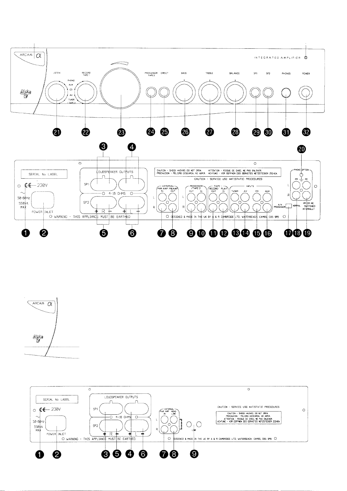
Front & Rear Panel Diagrams
0
Alpha 9 Integrated Amplifier
POWER AMPl. lEiER
SP2 PHONES POWR
O O (Q
(i) ® 0 0
Alpha 9P Power Amplifier
Page 3

Safety Instructions " Please read before operating the equipment ENGLISH
SAFETY INSTRUCTIONS
This product was designed and manufactured to meet strict
quality and safety standards. There are, however, some
installation and operation precautions which you should be
particularly aware of:
1. Read Instructions - All the safety and operating
instructions should be read before the appliance is
operated.
2. Retain Instructions - The safety and operating
instructions should be retained for future reference.
3. Heed Warnings - Ali warnings on the appliance and in
the operating instructions should be adhered to.
4. Follow Instructions - All operating and use instructions
should be followed.
5. Water and Moisture - The appliance should not be used
near water - for example near a bathtub, washbowl,
kitchen sink, laundry tub, in a wet basement or near a
swimming pool, etc.
6. Carts and Stands - The appliance should be used only
with a cart or stand that is recommended by the
manufacturer.
6A. An appliance and cart combination should be moved with
care. Quick stops, excessive force, and uneven surfaces
may cause the appliance and cart combination to
overturn.
7. Wall or Celling Mounting - The appliance should be
mounted to a wall or ceiling only as recommended by the
manufacturer.
13. Cleaning - Unplug the unit from the mains supply before
cleaning. The appliance should normally only require a
wipe over with a clean, dry, lint-free cloth. If it is heavily
soiled then a cloth slightly dampened with a
water/washing up liquid solution may be used. Dry the unit
afterwards with a dry cloth. We do not advise the use of
furniture type cleaning sprays/polishes as this can cause
white marks, which are very difficult to remove, if the unit
is then wiped over with water.
14. Power Lines - An outdoor antenna/ aerial should be
located away from power lines.
15. Non-use Periods - The power cord of the appliance
should be unplugged from the outlet when left unused for
a long period of time.
16. Object and Liquid Entry - Care should be taken so that
objects do not fall and liquids are not spilled into the
enclosure through any openings.
17. Abnormal Smell - If an abnormal smell or smoke is
detected from the appliance, immediately turn the power
off and unplug the unit from the wall outlet. Contact your
dealer immediately.
18. Damage Requiring Service - The appliance should be
serviced by qualified service personnel when:
A. The power-supply cord or the plug has been damaged or:
B. Objects have fallen, or liquid has spilled into the appliance
or:
C. The appliance has been exposed to rain or:
8. Ventilation - The appliance should be situated so that its
location or position does not interfere with its proper
ventilation. For example, the appliance should not be
situated on a bed, sofa, rug or similar surface that may
block the ventilation openings or placed in a built-in
installation, such as a bookcase or cabinet that may
impede the flow of air through the ventilation openings.
9. Heat - The appliance should be situated away from heat
sources such as radiators, heat registers, stoves or other
appliances (including amplifiers) that produce heat.
10. Power Sources - The appliance should be connected to
a power supply only of the type described in the operating
instructions or as marked on the appliance.
11. Grounding - Precautions should be taken so that the
grounding means of the appliance is not defeated.
12. Power-Cord Protection - Power supply cords should be
routed so that they are not likely to be walked on or
pinched by items placed upon or against them, paying
particular attention to cords and plugs, convenience
receptacles and the point where they exit from the
appliance.
D. The appliance does not appear to operate normally or
exhibits a marked change in performance or:
E. The appliance has been dropped or the enclosure
damaged.
19. Servicing - The user should not attempt to service the
appliance beyond that described in the operating
instructions.
All other servicing should be referred to qualified service
personnel.
Page 4

Introduction & Installation
ENGLISH
INTRODUCTION
The Arcam Alpha 9 integrated amplifier, is derived from the
highly successful Arcam Delta 290 model. It is rated at 70 watts
per channel into 8 ohms. The Alpha 9 is extremely versatile and
suitable for both conventional and Audio Visual (home cinema)
based systems.
It can be used as an integrated amplifier or as a preamplifier to
drive external power amplifiers. The preamp out sockets also
allow the addition of an Alpha 9P power amplifier to give a true
bi-amplified system. In this configuration the power amplifiers
within the Alpha 9 integrated amplifier are retained to drive the
loudspeakers’ treble units whilst using the Alpha 9P to drive
their bass/midrange units.
In addition to this the Alpha 9 integrated amplifier can also be
used as a stand alone power amplifier via its “power amp in”
sockets or combined with suitable loudspeakers and an AV
processor, such as the Arcam Xeta 2, to form a very high
performance home cinema system.
The Alpha 9P is a matching 70 watts per channel power
amplifier designed to complement the Alpha 9 integrated
amplifier. It offers an easy upgrade path for owners of the
Alpha 9 integrated amplifier (or the Delta 290 integrated
amplifier) to provide a bi-amplified system.
It may also be used with Arcam’s Alpha 7 and 8 integrated
amplifiers, either as a simple power booster or as part of a high
performance bi-amplified system.
It can be used with almost any preamplifier and is ideal for
upgrading both hi-fi and Audio Visual systems.
This manual is in four parts:
NOTICE FOR U.K. OWNERS ONLY
If the plug is removed then the remaining lead must be
rewired as follows:
The blue wire must be connected to the terminal which
is coloured blue or marked with the letter N.
The brown wire must be connected to the terminal
which is coloured brown or marked with the letter L.
The green and yellow wire must be connected to the
terminal which is coloured green and yellow, or marked
with the letter E or the safety earth symbol.
When replacing the fuse in the supplied moulded mains
plug, the integral fuse holder/cover must always be
refitted. Use a 5 amp fuse.
SAFETY STANDARD
■ This product has been designed to meet the I EC 6!
international electrical safety standard.
MAINS SUPPLY CONNECTIONS
e Insert the lEC line socket of the mains lead fully into the
power inlet on the rear panel. Connect the other end to
your mains supply.
This section has information relevant to both the Alpha
9 and Alpha 9P.
Alpha 9 integrated amplifier operating instructions.
C. Alpha 9P power amplifier operating instructions.
D. Instructions on how to bi-wire or to bi-amplify (“bi-amp”)
your loudspeakers.
N.B. Circled numbers e.g. refer to items on the diagrams
inside the flap of the front cover.
Section A
INSTALLATION
O Check that your mains supply voltage agrees with the
voltage setting indicated on the rear panel of the unit.
■ If your mains supply voltage is different, consult your
Arcam dealer.
MAINS SAFETY
■ This product is normally supplied with a moulded mains
plug already fitted to the lead. If for any reason the plug
needs to be removed, it must be disposed of
immediately and securely, as it is a potential shock
hazard when inserted into a mains socket.
CAUTION: Your Alpha 9 and Alpha 9P generate heat when in
use, particularly at higher volumes. It is therefore most
important never to obstruct the ventilation slots on the top and
bottom of the unit as this will cause overheating.
If the temperature of the internal heatsinks rises above a safe
level, then a thermal cut out inside the amplifier will operate.
The POWER LED on the front panel will turn amber and the
output protection relays will temporarily remove the feed to the
loudspeakers. The system will reset itself as the heatsinks cool
down.
Please note that under certain conditions it is possible for the
Alpha 9 or Alpha 9P's thermal cut out to operate when playing
music at very high levels.
This might for example happen when continuously playing
heavily compressed rock music "flat out" into low impedance
(4-6 ohm) speakers. If this happens to you, the cure is to turn
the volume down slightly and ensure the amplifier is properly
ventilated.
It is important to point out that when playing a heavily recorded
CD it is possible to drive the Alpha 9 at full power despite the
fact that the volume control is only at 10 or 11 o'clock. This is
because of the high output voltage from a CD player. However
the Alpha 9 also has to be capable of giving full power output
from much lower level sources, such as tuners and cassette
decks. Using these sources, the volume control setting will be
much higher before overload sets in.
Warning: This apparatus must be earthed.
Page 5

Alpha 9 Integraded Amplifier - Section B
Please refer to drawing inside front cover.
LOUDSPEAKER CONNECTIONS
ENGLISH
■ The amplifier is fitted with BFA (British Federation of
Audio) loudspeaker connectors, which are designed to
meet EU safety standards.
The BFA connector will accept spade terminals, bare
wires up to 4mm in diameter or a BFA plug. BFA plugs
are available from your Arcam dealer.
■ The speaker terminals are colour coded red for positive
and black for negative. These terminals are also
labelled 'R' for the right channel speakers and 'L' for the
left channel speakers.
©o Connect terminals © to your right speaker and
terminals © to your left speaker, ensuring correct
polarity.
■ Connect the red cable termination to the red terminal
and the other cable termination to the black terminal. If
your speaker cable has bare ends, the positive
conductor can usually be identified by a ridge or
coloured marking.
Ensure that no stray strands are allowed to touch
another cable or the amplifier's casing. This can cause
a short circuit and damage your amplifier!
©,© To drive a second pair of speakers, connect terminals
© to the right speaker and terminals © to the left
speaker, ensuring correct polarity.
■ The Alpha 9 can drive two pairs of loudspeakers,
simultaneously if required, providing both pairs are rated
between 8 and 16 ohms. Either pair can be selected
using the switches labelled SP1 and SP2 on the front
panel. To avoid overheating, the combined load
impedance as seen by the amplifier should not fall below
4 ohms per channel.
TAPE 1 RECORD OUT - Connect to your tape deck's
input (RECORD).
TAPE 1 PLAY IN - Connect to your tape deck's output
(PLAY).
TUNER - For connecting your radio tuner.
A/V - Suitable for connecting an Audio-Visual product
such as a VCR, Laserdisc player or Nicam tuner.
CD - For connecting your CD player or DAC (digital to
analogue convertor).
AUX - For connecting any unit with a line level output,
eg. tape deck, tuner etc.
PHONO OPTION - Please note: The phono inputs are
on a separate plug-in module which your Arcam dealer
or distributor can supply and fit.
This module is compatible with most high output moving
coil and moving magnet cartridges (MM) and low output
moving coil cartridges (MC).
MM or MC is selected via an internal switch. Your
cartridge type should be specified when the module is
fitted.
MM - For connecting a turntable fitted with a high output
moving coil or a moving magnet (MM) cartridge.
MC - For connecting a turntable fitted with a low output
moving coil (MC) cartridge.
GROUND TERMINAL - For connecting your turntable's
earth lead (if fitted).
CONNECTING YOUR SOURCE COMPONENTS
■ Using a suitable pair of interconnect cables, insert the
red phono plugs into the sockets labelled 'R' and the
other phono plugs into the sockets labelled 'L'.
All the line inputs (not PHONO) have the same
sensitivity and may be used with equipment other than
that labelled, if you need to do so.
© PROCESSOR/TAPE 2 RECORD OUT - Connect to your
tape deck's input (RECORD) or to your A/V processor's
Tape or Line inputs.
© PROCESSOR/TAPE 2 PLAY IN - Connect to your tape
deck's output (PLAY) or to your AA/ processor's Tape or
Line outputs.
■ If you have only one tape deck connect it to the TAPE
1 sockets.
OPERATION OF THE ALPHA 9 INTEGRATED AMPLIFIER
© NORMAL7 AA/READY SWITCH - (This switch is found
on the rear panel.)
With the switch set to NORMAL the unit functions as a
standard amplifier. For use with an /W decoder with its
own volume control, such as the Arcam Xeta 2, set the
switch to '/W READY'. This bypasses the Alpha 9's
volume control when 'PROCESSOR/TAPE 2' input is
selected, to provide a fixed gain stereo amplifier.
The volume control and MUTE cannot be operated by
remote in this situation. >
CAUTION: Do not set the switch to AN READY if you
have a cassette deck connected to the PROCESSOR/
TAPE 2 input.
This will bypass the volume control when you push the
PROCESSOR/ TAPE 2 button in and send the signal
straight into the power amplifier section. This could give
an extremely high sound output sufficient to damage
your loudspeakers.
® LISTEN SELECTOR - Selects the input you wish to
listen to. This signal also goes to the TAPE 2 output
sockets for recording onto a cassette deck or for
external processing. The selector can also be operated
by remote control. (See Remote Control Functions).
Page 6

ENGLISH
RECORD SELECTOR - Selects the input you wish to
record onto TAPE 1. This operates independently of the
LISTEN function. Alternatively this switch can also be
used as a simple ‘second zone’ selector, routing a
chosen source signal at line level to a second amplifier
operating in another room in the house.
VOLUME - Adjusts the volume level of the loudspeakers
and headphones.
Note that with the volume at minimum it may be possible
to still hear music very faintly. This is normal.
The VOLUME control is motorised and can be controlled
remotely with the supplied remote control handset (see
Remote Control functions for more details).
PROCESSOR/TAPE 2- This is a tape loop to permit you
to monitor a recording made on a 3 head cassette deck.
It can also be used to enable line inputs to be sent to an
external surround decoder such as the Arcam Xeta 2 for
processing, before being routed back to the amplifier.
For playback from a cassette deck or to reconnect the
output from an AA/ processor attached to TAPE 2 press
the button in.
With the button out the ‘loop’ is taken out of circuit, so
that the input signal chosen with the LISTEN selector is
played through the amplifier.
Note: PROCESSOR/TAPE 2 is not remote controllable.
The headphone socket is always switched on,
irrespective of the positions of switches ® and ®.
POWER - Switches the unit on and off.
POWER LED - The LED above the POWER switch will
initially glow amber. After a few seconds, it will glow
green. When the LED glows amber, the speakers are
disconnected and an internal protection circuit is
activated or the unit has been muted by use of the
remote control. If this LED glows amber during normal
use it may be due to the amplifier overheating or an
output overload. Check the amplifier is properly
ventilated.
Switch the amplifier off and wait for 2-3 minutes before
switching on again. If the LED continues to glow amber,
switch the unit off, remove all the speaker cables and
switch on again. If the LED goes to green upon switch
on then check the speaker and speaker cables for short
circuits before reconnecting them.
If the LED continues to glow amber with no speakers
connected contact your Arcam dealer.
REMOTE RECEIVER - The remote receiver is behind
the badge in the top left hand corner of the unit. Ensure
the remote receiver is not obscured or commands from
the remote control handset will not be received.
DIRECT - When this button is pushed in it bypasses the
bass, treble and balance controls. This affects all inputs,
and will generally give a small improvement in sound
quality and a useful reduction in the level of background
hiss.
BASS - Rotate clockwise to boost the bass response
and anti-clockwise to cut the bass response. For a flat
response leave in the central ‘click’ position.
TREBLE - Rotate clockwise to boost the treble response
and anti-clockwise to cut the treble response. For a flat
response leave in the central ‘click’ position.
The range of the tone controls has been deliberately
limited to approximately -(■/- 8dB at the frequency
extremes.
BALANCE - Rotate clockwise or anti-clockwise to move
the position of the stereo image. This may be necessary
if it is not possible to sit centrally between the speakers.
In normal use leave in the central 'click' position.
SP1 - Selects or defeats the main pair of speakers.
Push the button in to select.
SP2 - Selects or defeats the secondary pair of speakers.
Push the button in to select.
Important note: If both switches are turned off then the
amplifier will appear not to be functioning, as all
speakers will be switched off!
TAPE RECORDING
■ Both sets of tape sockets (TAPE 1 and TAPE 2) are
identical in sensitivity and suitable for use with almost
any type of recorder (cassette, hi-fi VCR, reel to reel,
DAT, etc.)
■ Use the RECORD selector to route the required signal
to a cassette deck connected to the TAPE 1 RECORD
OUT sockets.
■ Use the LISTEN selector to route the required signal to
a cassette deck connected to the TAPE 2 RECORD
OUT sockets.
■ RECORDING (TAPE 1): Any input signal available on'
the Alpha 9 may be routed to the TAPE 1 output sockets
by using the RECORD selector to select the appropriate
input.
Set your tape recorder into its recording mode and the
selected input will be recorded.
Selecting the same input with the LISTEN selector will
not affect the signal sent out to the recorder and will now
enable you to listen to the signal being recorded. You
may listen to another input whilst recording on TAPE 1
by use of the LISTEN selector.
If your tape recorder is a 3 head design, this will allow A-
B monitoring of the actual recording while it is taking
place. Sv^itching the LISTEN switch between the
original source and TAPE 1 during recording will then
enable you to make a true ‘before’ and ‘after’ (A-B)
comparison.
FIEADPFIONES SOCKET - Accepts headphones rated
between 8 ohms and 2kohms fitted with a 6.3mm stereo
jack plug. If your headphones are fitted with a different
plug contact your dealer for a suitable adaptor. If you
wish to listen on headphones only, use SP1 and SP2 (if
necessary) to mute the speakers.
■ TAPE TO TAPE DUBBING: The Alpha 9 allows two way
tape dubbing (copying) from TAPE 1 to TAPE 2 or vice
versa.
For example, to copy from a recorder connected to the'
TAPE 2 sockets to a recorder connected to TAPE 1, first
switch the RECORD selector on the Alpha 9 to TAPE 2.
This routes the TAPE 2 signal to TAPE 1 's output.
Page 7

ENGLISH
Then set the first tape recorder into its 'record' mode and
the second to 'playback' mode to enable the transfer to
take place. If you wish to monitor the transfer while it is
taking place switch LISTEN to TAPE 1.
To record from TAPE 1 to TAPE 2 set listen to TAPE 1.
It does not matter what position the RECORD selector Is
in. To monitor push the PROCESSOR/TAPE 2 button
in.
PRE/POWER CONNECTIONS
© PWR AMP IN - To use your Alpha 9 just as a power
amplifier, connect the output of your pre-amplifier to the
PWR AMP IN sockets. The Alpha 9's internal selector
switch should be set to the EXT INPUT position to
disconnect the preamp stages of the unit. Contact your
dealer or Arcam for more details.
Under these circumstances it has exactly the same
specification and performance as an Alpha 9P power
amplifier.
® PREAMP OUT - To use your Alpha 9 as a pre-amplifier,
connect the PREAMP OUT sockets to the input sockets
of your power amplifier. With a power amplifier of the
correct gain (e.g. An Arcam Alpha 9P or Delta 290P) this
allows you to bl-amplify (“bi-amp”) suitable
loudspeakers, giving significant improvements in sound
quality (see section on BI-WIRING/ BI-AMPING).
REMOTE CONTROL FUNCTIONS
■ Your Alpha 9 amplifier is supplied with the Arcam CR35
infra-red remote control handset, which has buttons to
allow the simple operation of other products. It is
supplied with 2 AA batteries - ensure these are inserted
correctly.
■ The remote allows you to operate the Alpha 9 plus some
basic functions of an Arcam (except the Alpha One CD
player, which uses a different remote control language)
or Philips based CD player, a remote controlled tuner
(such as the Arcam Delta 280* or Alpha 8 tuner) and the
Arcam Delta Black Box 500 DACC (Digital Audio Control
Centre).
* Note: versions of the Delta 280 FM tuner manufactured
before April 1995 will not respond to the programme
up/down buttons on the CR35.
■ REMOTE MODE - The Alpha 9 is factory-set to enable
the Arcam CR35 or Arcam CR200 System Remote
automatically to synchronise the operation of any Arcam
CD player or transport, remote control tuner (and with a
CR200, the Arcam Delta 100 cassette deck) with the
LISTEN selector on the Alpha 9, all at the touch of a
single button.
For example, using the CR35 remote, press PLAY, and
the CD player will start the disc and the LISTEN switch
of the Alpha 9 will select the CD input. If automatic
operation is not required it can be disabled by your
dealer by fitting an internal link. The LISTEN selector
switch can still be operated by either remote control
handset.
Note; The ‘STBY’, ‘DISP’ and ‘VCR’ buttons do not initiate any
functions within the Alpha 9 amplifier. 'DVD' can be
used to select the aux input on the Alpha 9.
The MUTE button mutes the speaker connections and
pre-amp outputs. Both tape outputs and the headphone
socket remain active. In MUTE mode the power LED will
turn amber until mute is disabled by either pressing
MUTE again or pressing volume -/+.
Section C
ALPHA 9P POWER AMPLIFIER
Please refer to drawing inside front cover.
LOUDSPEAKER CONNECTIONS
Connect up as per instructions for the Alpha 9 integrated
amplifier.
CONNECTING YOUR SOURCE COMPONENT
© PWR AMP IN - Connect to your pre-amplifier outputs or
the PREAMP OUT sockets of an Arcam Delta 290 or
Alpha 9 amplifier.
® MONO LINK - The Alpha 9P can be configured to
provide two mono loudspeaker outputs from a single
input.
Using the U-link ® supplied, connect the MONO LINK
sockets ® together.
Utilising one Alpha 9P per loudspeaker in this manner
will allow bi-amplifying of bi-wireable loudspeakers. This
is particularly beneficial for top quality stereo
installations with a separate pre-amplifier, or for the left,
centre and right channel loudspeakers in a five speaker
Dolby Pro Logic system. Contact your Arcam dealer for
more detailed information.
■ Daisy Chain - The Alpha 9P is capable of driving further
Alpha 9P amplifiers (or any other power amplifier), to
drive more speakers (eg. those in other rooms or triamplified speakers etc). Connect the extra power
amplifier inputs to the MONO LINK outputs © left to left,
right to right.
FRONT PANEL
SP1 and SP2 - Pressing the SP1 switch turns on the
speakers connected to the SP1 (upper) set of output
terminals on the rear panel. Similarly the SP2 switch
turns on the speakers connected to the SP2 (lower) set
of output terminals.
■ Both the SP1 and SP2 switches can be turned on at the
same time, provided that the combined impedance of
the two pairs of speakers does not fall below 4 ohms per
channel.
Important note: If both switches are turned off then the
amplifier will appear not to be functioning, as all speakers will
be switched off!
® HEADPHONES SOCKET - Accepts headphones rated
between 8 ohms and 2k ohms fitted with a 6.3mm stereo
jack plug. If your headphones are fitted with a different
plug contact your dealer for a suitable adaptor.
■ The headphone socket is always switched on,
irrespective of the positions of switches © and ©
© POWER - Switches the power on and off.
Page 8

® POWER LED - This will initially glow amber. After a few
seconds, it will glow green. When the LED glows
amber, the speakers are disconnected and an internal
protection circuit is activated.
■ If this LED glows amber during normal use it may be due
to the amplifier overheating or an output overload.
Check the amplifier is properly ventilated. Switch the
amplifier off and wait for 2-3 minutes before switching on
again.
If the LED continues to glow amber, switch the unit off,
remove all the speaker cables and switch on again. If
the LED goes to green on switch on then check the
speaker and speaker cables for short circuits before
reconnecting them.
If the LED continues to glow amber with no speakers connected
contact your dealer or Arcam.
Section D
BI-WIRING/BI-AMPING INSTRUCTIONS
ENGLISH
BI-WIRING USING BOTH SETS OF CONNECTIONS ON
AMP
Many modem loudspeakers are equipped with four connection
terminals. This provides direct access to the high frequency
and low frequency filter networks and associated drive units
within the loudspeaker. Overall performance can be enhanced
by making use of these separate connections.
WARNING: Do not make any connections to your amplifier
while it is switched on and connected to the mains supply.
Please check all connections thoroughly before attempting to
re-connect the mains power supply. Always ensure that the
volume control on your amplifier is set to a minimum before
switching on.
BI-WIRING
Bi-wiring uses four conductors, one for each terminal, to
enhance dramatically the performance of your loudspeakers.
Bi-wiring eliminates the signal distortion arising from the low
and high frequency currents interacting with one another within
a single cable, as used in conventionally wired systems.
HOW TO BI-WIRE YOUR LOUDSPEAKERS
1. Remove the shorting links from each of the red and
black terminal pairs on the rear of your loudspeakers.
BI-WIRING USING ONE SET OF CONNECTIONS ON
AMP
2. You will need two lengths of loudspeaker cable per
loudspeaker (which may be joined at the amplifier end)
or a suitably terminated cable set capable of being used
for bi-wiring in one length.
3. Connect the cables as per diagrams, dependant on your
cable wiring, ensuring correct polarity at all times. The
positive (+) connections on the right loudspeaker must
go to the positive (-i-) connections on the right channei of
the amplifier and the negative (-) connections on the
right loudspeaker must go to the negative (-)
connections on the right channel of the amplifier etc.
Page 9

ENGLISH
BI-AMPING
The performance of your system can be further enhanced over
that achieved with bi-wiring, by extending the same principal
one stage further to include separate amplification for the low
and high frequency speaker drive units as well as separate
loudspeaker cables. This is known as biamplifying, or bi-amping
for short.
To implement bi-amping therefore requires four amplification
channels. In practice this is done by using two stereo
amplifiers; when one of these is an integrated amplifier it is best
to use this drive the high frequency (HF) units whilst the
outboard power amplifier is used to drive the low frequency (LF)
units.
We recommend that you use identical amplifiers to avoid
potential imbalances in sonic performance and sensitivities.
The Alpha 9/9P combination is ideal, as is the Delta 290/290P.
It is however possible to mix the Alpha 9 and Delta 290 range
of amplifiers.
HOW TO SET UP A BI-AM PED SYSTEM
1. Remove the shorting links from each of the red and
black terminal pairs on the rear of your loudspeakers.
THIS IS ESSENTIAL OR DAMAGE TO YOUR
AMPLIFIERS MAY RESULT WHICH IS NOT COVERED
UNDER WARRANTY.
ADDING AN ALPHA 9P TO AN EXISTING ALPHA 9 INTEGRATED AMPLIFIER
If you are using an Alpha 9, an Alpha 9P can be added to biamplify a pair of bi-wireable loudspeakers. This will reap
substantial improvements in sound quality if the following
advice is observed.
■ Always switch on the Alpha 9 and allow it to stabilise
(indicator light turns green) before switching on the
Alpha 9P.
■ The Alpha 9 and Alpha 9P power amplifier are placed on
separate shelves.
Stacking the units on top of each other will reduce the
sound quality slightly. It will also reduce ventilation and
consequently the continuous power handling capability.
■ The existing Alpha 9 should be used to drive the
loudspeakers' HF (high frequency) units. The new Alpha
9P is utilised for the LF (bass) drivers, as shown in the
wiring diagram below.
■ At the end of a listening session the Alpha 9P should
always be turned off first.
■ High quality interconnect cables should be used
between the Alpha 9 and Alpha 9P.
■ The use of high quality interconnect and speaker cables
in your system is essential to obtain good sound quality.
Contact your dealer or Arcam for further details and
recommendations.
Note: The second set of speaker terminals (SP2) on
both units can be used to drive extra loudspeakers in
other rooms provided the impedance of these are 8
ohms or more.
BI-AMPING YOUR LOUDSPEAKERS
INTEGRATED AMPLIFIER
POWER AMPLIFIER
2. You will need two lengths of loudspeaker cable (or a
suitably terminated cable capable of being used for bi
wiring in one length) and one stereo amplifier per
frequency band.
3. Connect your system as per the diagram opposite
ensuring correct polarity at all times. The positive (+)
connections on the loudspeaker must go to the positive
(+) connections on the amplifier and the negative (-)
connections on the right loudspeaker must go to the
negative (-) connections on the right channei of the
amplifier etc. You also need to make a connection from
the preamp out sockets of your integrated amplifier, or
preamplifier, to the power amp in sockets of the power
amp.
■ WARNING - Ensure that the TERMINAL LINKS ARE
REMOVED on the loudspeakers before switching on
the amplifiers. Failure to do this could cause
damage to one or both amplifiers and this is not
covered under the warranty.
Page 10

Guarantee Information ENGLISH
GUARANTEE FOR UK SALES
This equipment is guaranteed for two years from the date of purchase (parts and
labour only), provided that it was originally purchased from an authorised dealer
under a consumer sale agreement, (The words "consumer sale" shall be construed
in accordance with Section f 5 of the Supply Of Goods [Implied Terms] Act 1973).
The manufacturer can accept no responsibility for defects arising from accident,
misuse, abuse, wear and tear, neglect or through unauthorised adjustment and/or
repair, neither can they accept responsibility for damage or loss occurring during
transit to or from the person claiming under this guarantee.
This guarantee is applicable within the UK only. It is transferable to subsequent
purchasers, but the liability of the manufacturer is limited to the cost of repair of the
defective parts and under no circumstances extends to consequential loss or
damage.
CLAIMS UNDER THIS GUARANTEE
This equipment should be packed in the original packing and returned to the dealer
from whom it was purchased, or failing this, directly to Arcam, It should be sent
carriage prepaid by a reputable carrier - NOT by post. No responsiblity can be
accepted for the unit whilst in transit to the factory, or an agent, and customers are
therefore advised to insure the unit against loss or damage whilst in transit.
If the original packing is not available, replacement packing can be purchased from
Arcam.
DO NOT CONSIGN THE EOUIPMENT TO ARCAM UNLESS YOU HAVE BEEN
SPECIFICALLY REQUESTED TO DO SO BY THE CUSTOMER SUPPORT
DEPARTMENT.
DO NOT UNDER ANY CIRCUMSTANCES ATTEMPT TO DISASSEMBLE THE
EQUIPMENT BEFORE DESPATCH.
You can contact the manufacturer at the following address:
ARCAM Customer Support Department,
Pembroke Avenue,
Denny Industrial Centre,
Waterbeach,
Cambridge,
CB5 9PB,
England.
Telephone: -r44 (0)1223 203203
Fax: -r44 (0)1223 863384
e-mail: custserv@arcam.co.uk
GUARANTEE FOR SALES IN THE EUROPEAN ECONOMIC AREA (EEA)
This unit is covered by a European Economic Area warranty, provided to you under
the terms of Article 85 of the Treaty of Rome 1957.
This entitles you to have the unit repaired free of charge, during the first two years
after purchase, at any authorised Arcam distributor within the EEA, provided that
it was purchased from an authorised ARCAM dealer or distributor within the EEA.
The manufacturer can accept no responsibility for defects arising from accident,
misuse, abuse, wear and tear, neglect or through unauthorised adjustment and/or
repair, neither can they accept responsibility for damage or loss occurring during
transit to or from the person claiming under this guarantee.
Countries of the European Economic Area are: Belgium, Holland, Nonway, Iceland,
Lichtenstein, Luxembourg, Greece, Germany, France, Spain, Portugal, Eire, Italy,
Austria, Denmark, Sweden, Great Britain, Finland and Switzerland. This includes
the Canary Islands, the Channel Islands, the Isle of Man, Corsica and Sardinia.
This warranty remains in force for two years from the date of purchase as long as
the unit remains in free circulation. Units exported from the EEA and subsequently
re-imported are not subject to this warranty.
CLAIMS UNDER GUARANTEE
This equipment should be packed in the original packing and returned to the dealer
from whom it was purchased, or failing this, directly to the Arcam distributor in the
country of residence. It should be sent carriage prepaid by a reputable carrier NOT by post. No responsiblity can be accepted for the unit whilst in transit to the
dealer or distributor and customers are therefore advised to insure the unit against
loss or damage whilst in transit.
For further details contact Arcam at:
ARCAM Customer Support Department, Pembroke Avenue, Denny Industrial
Centre, Waterbeach, Cambridge, CB5 9PB, England.
Telephone: -t-44 (0) 1223 203203 Fax: +44 (0) 1223 863384
e-mail: custserv@arcam.co.uk
GUARANTEE FOR SALES IN THE REST OF THE WORLD
This equipment is guaranteed in the country of purchase only, provided that it was
purchased from an authorised ARCAM dealer or distributor.
The manufacturer can accept no responsibility for defects arising from accident,
misuse, abuse, wear and tear, neglect or through unauthorised adjustment and/or
repair, neither can they accept responsibility for damage or loss occurring during
transit to or from the person claiming under this guarantee.
You should state clearly your name and address, the date and place of purchase
together with a brief description of the fault.
In the event of equipment being returned which, after having been tested, is found
to comply with the published specification, the manufacturer reserves the right to
charge a reasonable fee for testing the equipment and for the return carriage.
THIS GUARANTEE IN NO WAY VARIES OR REMOVES A PURCHASER'S
STATUTORY RIGHTS.
Full details of the guarantee can be obtained from the distributor in the country of
purchase.
For your convenience a list of Arcam distributors is included in the enclosed ‘After
Sales Care Program' leaflet. For any countries not listed please contact Arcam
Customer Support directly.
CLAIMS UNDER GUARANTEE
This equipment should be packed in the original packing and returned to the dealer
from whom it was purchased, or failing this, directly to the Arcam distributor in the
country of purchase. It should be sent carriage prepaid by a reputable carrier NOT by post. No responsiblity can be accepted for the unit whilst in transit to the
dealer or distributor and customers are therefore advised to insure the unit against
loss or damage whilst in transit.
Page 11

TECHNICAL SPECIFICATIONS
ALPHA 9 INTEGRATED AMPLIFIER
Output power ( 20Hz-20kHz at 0.5%THD)
Harmonic Distortion, 60W, 8Q at 1kHz
Peak current rating
Tone controls (typical variation)
L/R Crosstalk
INPUTS Line inputs:
Noise (CCIR) ref. rated power
Input impedance
Overload margin
A/V loop input (AA^ mode)
Input impedance
Power amp in
Input impedance
Phono board (if fitted):
Noise (CCIR) ref. rated power
Input impedance
Overload margin
OUTPUTS Preamplifier Output
Nominal output level
Maximum output level
Output impedance
Tape/ AUX outputs:
Output impedance
Headphones:
Maximum output ievel into 600Q
Output impedance
70W, both channels into 8Q
90W, single channel into 8Q, 1kHz
MOW, single channel into 40, 1kHz
0.02% typical
± 18 amps
± 8dB at 50Hz and 10kHz
-65dB at 1kHz
Sensitivity 160mV
-98dB typical ("DIRECT" IN)
-90dB typical ("DIRECT" OUT)
5kO
>50dB
Sensitivity 670mV
5kO
Sensitivity 650mV
7.5kO
Sensitivity 2.6mV MM, 260/uV MC
-79dB MM, -73dB MC
47kO MM, 3000 MC
35dB
800mV
8V
1000
1000
8V
1000
Mains voltage
Power consumption(max)
Dimensions W/D/H mm.
Weight nett
Supplied accessories
ALPHA 9P POWER AMPLIFIER
Output power ( 20Hz-20kHz at 0.5%THD)
Harmonic Distortion, 60W, 80 at 1kHz
Peak current rating
Input impedance
Input sensitivity
Gain (1kHz)
Frequency response
Noise (CCIR) ref. rated power
Mains voltage
Power consumption(max)
Size W/D/H mm.
Weight nett
230V/115V ±12%
550VA
430x330x110
6.1kg (packed 7.6kg)
Mains lead
CR35 Remote Handset (inc. batteries)
70W, both channels, 80
90W, single channel, 80, 1kHz
MOW, single channel, 40, 1kHz
0.02% typical
± 18 amps
7.5kO
650mV for 70W/ 80
31.3dB±0.2dB
10Hz-20kHz±0.5dB
-lOOdB
230V/115V ±12%
550VA
430x320x110
5.8kg (packed 7.2kg)
Supplied accessories
E&O E.
Mains lead
Page 12

ARCAM
Pembroke Avenue, Waterbeach,
Cambridge, CB5 9PB, England.
Telephone: +44 (0) 1223 203203
Fax: +44 (0) 1223 863384
e-mail
custserv@arcam.co.uk
Issue 7/97
SH053E
 Loading...