

Page 1
Part Number:
Product
5620010
ARB REAR BAR
Description:
Suited to
TOYOTA FJ CRUISER
vehicle/s:
WARNING
ALSO, NOTE THE FOLLOWING:
♦ This product is not suitable for fitment with Toyota tow bar. View page 3 for tow bar options.
♦ This product must be installed exactly as per these instructions using only the hardware supplied.
♦ In the event of damage to any rear bar component, contact your nearest authorised ARB stockist.
♦ Do not use this product for any vehicle make or model, other than those specified by ARB.
♦ Do not remove labels from this rear bar.
♦ This product or its fixing must not be modified in any way.
♦ The installation of this product may require the use of specialized tools and/or techniques
♦ It is recommended that this product is only installed by trained personnel
♦ These instructions are correct as at the publication date. ARB Corporation Ltd. cannot be held
responsible for the impact of any changes subsequently made by the vehicle manufacturer
♦ During installation, it is the duty of the installer to check correct operation/clearances of all
components
♦ Work safely at all times
♦ Unless otherwise instructed, tighten fasteners to specified torque
ARB 4x4 ACCESSORIES
Corporate Head Office
42-44 Garden St Tel: +61 (3) 9761 6622
Kilsyth, Victoria Fax: +61 (3) 9761 6807
AUSTRALIA 3137
Australian enquiries sales@arb.com.au
North & South American enquiries sales@arbusa.com
Other international enquiries exports@arb.com.au
www.arb.com.au
Last Rev Date: 13/3/07 Page 1 of 10 Fitting instructions# 3786375
Copyright © 2005 by ARB Corporation Limited. All rights reserved, this document must not be reproduced without the express authority of ARB Corporation Ltd
Page 2

FITTING REQUIREMENTS
REQUIRED TOOLS FOR FITMENT OF PRODUCT:
Basic Tool Kit
Jigsaw Allen Key
Hacksaw
HAVE AVAILABLE THESE SAFETY ITEMS WHEN FITTING PRODUCT:
17mm Socket
Air Hacksaw
Protective eyewear
Hearing protection
NOTE: ‘WARNING’ notes in the fitting procedure relate to OHS situations, where to avoid a
potentially hazardous situation it is suggested that protective safety gear be worn or a safe work
procedure be employed. If these notes and warnings are not heeded, injury may result.
FASTENER TORQUE SETTINGS:
SIZE Torque Nm Torque lbft
M6 9Nm 4lbft
M8 22Nm 16lbft
M10 44Nm 32lbft
M12 77Nm 57lbft
Last Rev Date: 13/3/07 Page 2 of 10 Fitting instructions# 3786375
Copyright © 2005 by ARB Corporation Limited. All rights reserved, this document must not be reproduced without the express authority of ARB Corporation Ltd
Page 3

Fitting Kit 6172202 PARTS LISTING
APPLICATION. PART NO. QTY DESCRIPTION
Mount Assembly To Chassis
Mount Trim to Bar
Mount Aluminium to bar
6151097
4581050
4581049
3757043
6821166
6151256
6151300
3199913
6151256
6151300
3199912
8
M12 x 50 x 1.25
8
12mm Spring Washer
8
12mm Flat washer
1
Recovery Hook
2
Reflector
4
M6 Button Head Cap Screw
4
M6 Cage nut
1
Trim Panel
6
M6 Button Head Cap Screw
6
M6 Cage nut
1
Aluminium Trim
Optional Accessories
Also available for the FJ Cruiser is an ARB Tow bar. This tow bar can only be fitted
in conjunction with the ARB FJ Cruiser Rear Bar.
ARB FJ Cruiser Tow bar Part Number: 572 0010
Last Rev Date: 13/3/07 Page 3 of 10 Fitting instructions# 3786375
Copyright © 2005 by ARB Corporation Limited. All rights reserved, this document must not be reproduced without the express authority of ARB Corporation Ltd
Page 4
FITTING PROCEDURE
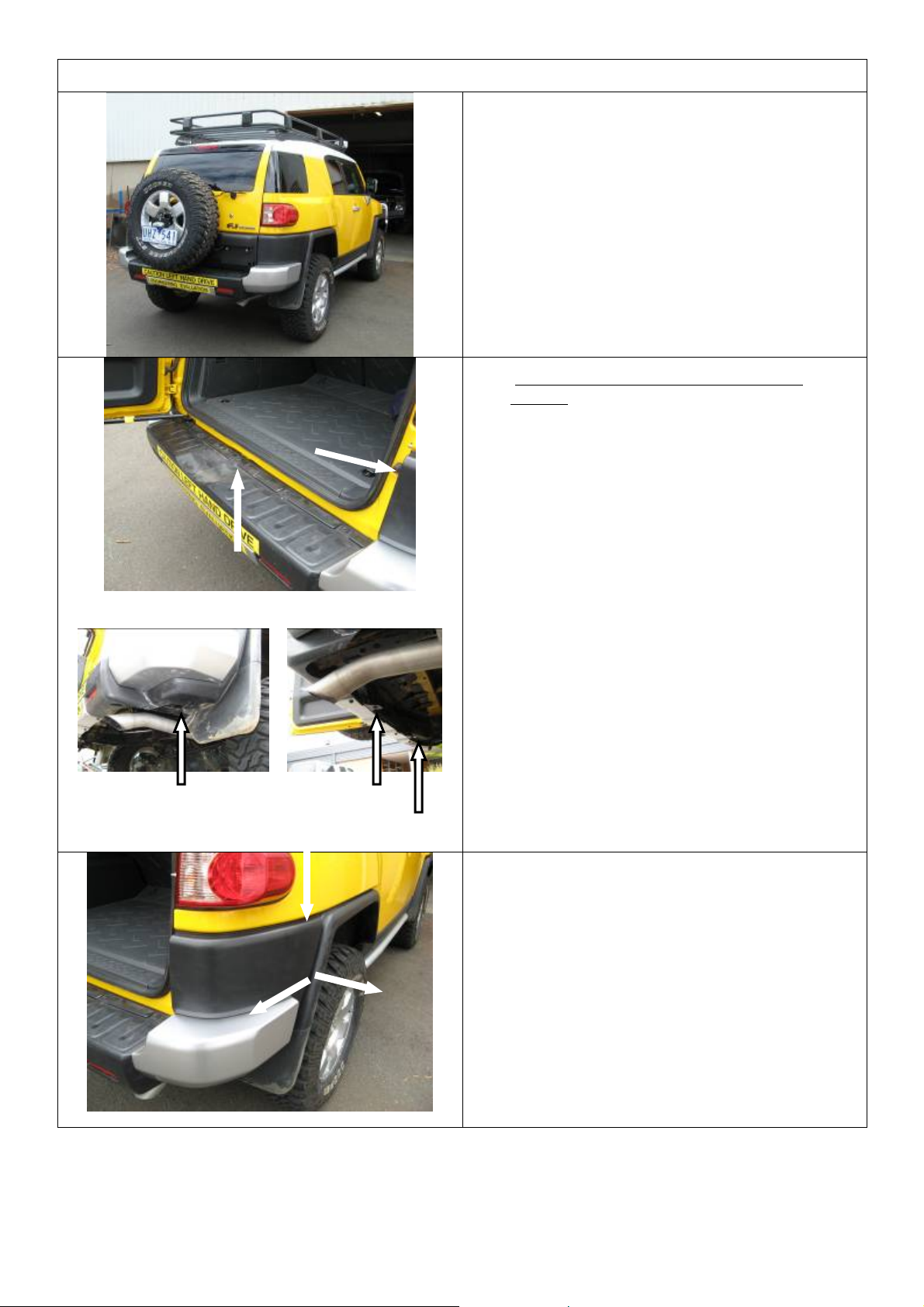
1. To fit the Rear Bar, the plastic bumper must
be cut. This is done at a later stage.
2. Removing the plastic bumper from the
vehicle.
4 top bolts
End screw to retain
Scrivet
2 underside bolts
There are 4 bolts along the top, 2 underneath
the centre of the bar, 1 screw on the
underside of each end, which must be
retained, and a scrivet located on the
passenger side of the vehicle in the door
jamb which should also be retained.
Also undo the connectors for the parking
sensors located in the lower corner of each
end of the bar.
3. Once all fasteners have been removed, the
bar can be pulled off the clips on each end by
pressing down on the top edge whilst pulling
the side out and back. Take care during this
operation as the corners of the bar must be
reused.
Last Rev Date: 13/3/07 Page 4 of 10 Fitting instructions# 3786375
Copyright © 2005 by ARB Corporation Limited. All rights reserved, this document must not be reproduced without the express authority of ARB Corporation Ltd
Page 5

Lift off foam
Remove bracket, left
and right
Remove brackets from
underside of body and
from chassis. Also
remove tow hook
4. Once the clips are undone, the bar can be
removed. With the bar removed the support
brackets, tow hook and foam can also be
removed.
5. With the bumper removed from the car it can
now be trimmed. First remove the silver end
caps by releasing all (5) retaining clips. Then
release the clips for the parking sensor wiring.
If the parking sensors are to be refitted,
remove them from the bar by sliding the large
plastic clip sideways and remove from bar.
Last Rev Date: 13/3/07 Page 5 of 10 Fitting instructions# 3786375
Copyright © 2005 by ARB Corporation Limited. All rights reserved, this document must not be reproduced without the express authority of ARB Corporation Ltd
Page 6

Measure 25mm down
and scribe line 1 here
Line 4
Line 2
Line 3
Line 5
6. Marking the cut lines
Corner section cut line
Images are of the left hand (drivers) side
First measure down 25mm from the rebate
and scribe a line (1) on the curved inner
face.
Then run a line (2) down the corner of the
vertical face and the centre section of the
bar, followed by a line (3) along the bottom
as shown.
Place a ruler between the end points of the
two lines and draw a line (4) as shown.
For the final line (5) join the top of line 2 and
the start of line 1 as shown.
This line can be cut to remove the corner
from the centre section
Line A
Square section cut line
Start by measuring 40mm from the edge and
draw a line (A) down using a square.
Then but the ruler into the plastic whilst
resting the top surface of the box section and
mark on each side of the ruler at 20mm
Repeat this process this time placing the
ruler between the two double ribs and
marking each side of the ruler at 35mm out.
Join the first 2 marks with a line (B), and the
second 2 marks with a line (C).
Line C Line B
Last Rev Date: 13/3/07 Page 6 of 10 Fitting instructions# 3786375
Copyright © 2005 by ARB Corporation Limited. All rights reserved, this document must not be reproduced without the express authority of ARB Corporation Ltd
Page 7

FITTING PROCEDURE
On the side of the box section measure a
point 110mm from the end and square a line
110mm
Line D
Line F
70mm
(D) down.
Turn the bar over to mark the cut lines
underneath. Place the ruler in the corner of
the box section and mark at 110mm.
Draw a line (E) from this point to the end of
line D
Place the ruler on the surface hard against the
double rib and measure out 70mm
Draw a line (F) from this point to the end of
line A
Finally draw a line (G) joining the end of line F
Line F
Line E
Line G
to the end of line E.
7. The final cut line viewed from underneath
8. The final cut line viewed from above.
The bar can now be cut using a hacksaw, air
hacksaw and/or jigsaw, Taking particular
care around the edge closest to the door as
this will be seen when the bar is fitted.
Take care when
cutting here
Last Rev Date: 13/3/07 Page 7 of 10 Fitting instructions# 3786375
Copyright © 2005 by ARB Corporation Limited. All rights reserved, this document must not be reproduced without the express authority of ARB Corporation Ltd
Page 8

9. Once the bumper has been cut, refit each
corner to the vehicle by clipping it the top and
side and refitting the screw to the underside.
Refit the scrivet on the passenger side.
Pull rubber towards
rear of vehicle
Push exhaust slightly towards
front of vehicle until it is
released from rubber mount as
shown
10. Before fitting the rear bar, the exhaust mount
must be released by pulling the rubber mount
towards the rear of the vehicle and allowing
the exhaust to drop slightly. This allows
access to the bolt holes.
11. The tab found below the door opening in the
centre of the car must be gently bent down to
vertical with a hammer.
3 Cage nuts each side
12. Before the bar is fitted, the M6 cage nuts
must be fitted to the outside 6 holes only.
Fitting the cage nuts to the centre holes will
be done once the bar is fitted.
Last Rev Date: 13/3/07 Page 8 of 10 Fitting instructions# 3786375
Copyright © 2005 by ARB Corporation Limited. All rights reserved, this document must not be reproduced without the express authority of ARB Corporation Ltd
Page 9

FITTING PROCEDURE
Passenger side Drivers side
(with trimmed clip)
13. If parking sensors are to be fitted, insert them
in the holes with the wiring pointing towards
the outside of the bar as shown.
NOTE: the passenger side sensor clip will
require trimming as shown below.
14. The rear bar can now be fitted.
Carefully slide the rear bar over the chassis,
taking care not to damage the plastic bumper.
This may require 2 people.
One person each side to lift bar into place
Large distance between bolts and
end of plate to the bottom
15. With the bar sitting on the vehicle, place the
recovery hook on with the large offset to the
bottom, and attach to the front face using
M12 x 50 x 1.25 bolts, 12mm flat washers
and 12mm spring washers.
Do not fully tighten.
16. Take the chassis spacer and place between
the chassis mount and the chassis of the
vehicle. Attach using M12 x 50 x 1.25 bolts,
12mm flat washers and 12mm spring
washers.
Check alignment of bar to vehicle, and then
tighten all bolts to specified torque
Last Rev Date: 13/3/07 Page 9 of 10 Fitting instructions# 3786375
Copyright © 2005 by ARB Corporation Limited. All rights reserved, this document must not be reproduced without the express authority of ARB Corporation Ltd
Page 10

17. Fitting the cover trim and aluminium top
With the door open, fit the 4 M6 cage nuts to
the centre holes of the rear bar, then place
the cover trim in position and fit using M6
Button head cap screws. Then place the
aluminium on top and fix using M6 Button
head cap screws.
Fitting trim panel
Fitting Aluminum plate
Then place the aluminium on top and fix using
M6 Button head cap screws.
Once fitted to the vehicle, peel the back off the
reflectors and stick them to the outer wings of
the bar as shown.
18. If re-fitting parking sensors, place the wiring
loom over the chassis rails and plug into the
socket at the bottom of each quarter panel.
There is a black clip which can be pressed
into a slot in the chassis to stop the wiring
moving.
19. Finally refit the exhaust mount by hooking the
exhaust into the hole in the rubber, and then
Push top and bottom
equally
pushing the rubber mount towards the front of
the vehicle without pushing the rubber off the
black pins on the chassis.
Last Rev Date: 13/3/07 Page 10 of 10 Fitting instructions# 3786375
Copyright © 2005 by ARB Corporation Limited. All rights reserved, this document must not be reproduced without the express authority of ARB Corporation Ltd
Page 11

Last Rev Date: 13/3/07 Page 11 of 10 Fitting instructions# 3786375
Copyright © 2005 by ARB Corporation Limited. All rights reserved, this document must not be reproduced without the express authority of ARB Corporation Ltd
 Loading...