

Page 1
ARB TOYOTA 80 SERIES
REAR STEP TOW BAR
Product number: 5611210
Optional
Wheel
Optional
Jerry Can
Carrier
Carrier
Left Hand Side
of vehicle (LHS)
Rear Step Tow Bar
Right Hand Side
of vehicle (RHS)
READ FITTING INSTRUCTIONS
CAREFULLY BEFORE PROCEEDING
08-10-09 Page 1 of 19
If you have any queries regarding the installation of this product please contact the distributor from whom it was purchased, or alternatively the ARB office in your state.
WA:(08) 9244 3553 NSW: (02) 9821 3633 ACT: (02) 6280 7475 SA: (08) 8244 5001 QLD: (07) 3872 3872 NT: (08) 8947 2262 TAS: (03) 6331 4190
Head Office – ARB Corporation Ltd VIC: 42-44 Garden Street, Kilsyth, Victoria, 3137 Tel: (03) 9761 6622 Fax: (03) 9761 6807
3783146
Page 2
USE PART No QTY DESCRIPTION
FIT TAIL LIGHT ASSEMBLIES
TO REAR BAR
6821172L 1 Tail Light Assembly – Left Hand Side (LHS)
6821172R 1 Tail Light Assembly – RHS
6151017 12 Bolt M6 x 16
6151128 8 Nut M6 flange
6151300 4 Nut M6 cage
6151046 12 Washer 6mm flat
3756681 2 Light mount cover bracket
FIT CAGE NUTS TO REAR
BAR
6151300 16 Nut M6 cage
6151303 4 Nut M8 cage
3756701 2 Locking pin bracket
FIT LOCKING PIN BRACKETS
TO REAR BAR
6151022 4 Bolt M8 x 25
6151132 4 Nut M8 flange
4581044 4 Washer 8mm flat
FIT LOOM TO VEHICLE 6821163 1 Loom
6151096 2 Bolt M12 x 40 x 1.25
4581049 4 Washer 12mm flat
FIT BAR TO REAR CROSS
MEMBER
4581050 4 Washer 12mm spring
3199773 2 Cross member nut plate
6151306 2 Nut M12 cage
6151255 2 Bolt M12 x 40 x 1.75
6151097 4 Bolt M12 x 50 x 1.25
6151340 2 Bolt M12 x 50 x 1.75
4581007 6 Washer ½” flat heavy duty gold zinc
FIT BAR TO UNDERSIDE OF
CHASSIS
4581050 6 Washer 12mm spring
5848309 2 Chassis packer front
5848310 2 Chassis packer rear
3199772 1 Chassis lower nut plate
6151306 2 Nut M12 cage
6151255 4 Bolt M12 x 40 x 1.75
4581007 4 Washer ½” flat heavy duty gold zinc
FIT BAR TO CHASSIS SIDE
4581050 4 Washer 12mm spring
3199771 2 Chassis side nut plate
6151306 4 Nut M12 cage
6522646 1 Centre cover panel
6151300 2 Nut M6 cage
6151352 2 Socket head cap screw M6 x 25 stainless steel
FIT CENTRE COVER PANEL
6151207 2 Bolt M6 x 25
6151046 4 Washer 6mm flat
6151042 4 Washer 6mm spring
5848302 2 Packer black nylon
6250003 2 Spacer 8mm thick gold zinc
08-10-09 Page 2 of 19
3783146
Page 3
FIT END SURROUNDS TO
REAR BAR
FIT END SURROUND
BRACES
3131192L 1 End surround LHS
3131192R 1 End surround RHS
6151083 6 Bolt M8 x 35
6151132 6 Nut M8 flange
4581044 6 Washer 8mm flat
6250003 6 Spacer 8mm thick gold zinc
3756757L 1 End surround brace LHS
3756757R 1 End surround brace RHS
6151017 2 Bolt M6 x 20
6151046 2 Washer Flat M6
6151128 2 Nut Flange M6
6151083 4 Bolt M8 x 35
6151021 4 Bolt M8 x 20
6151132 4 Nut M8 flange
4581044 8 Washer 8mm flat
4581046 8 Washer 8mm spring
3199774 1 Wing brace nut plate
6151303 2 Nut M8 cage
3162478L 1 Vertical trim
3162478R 1 Vertical trim
3162482L 1 End surround trim
FIT URETHANE TRIMS
3162482R 1 End surround trim
6821166 2 Reflector
6151162 10 Nut M6 nyloc
4581082 10 Washer 6mm flat heavy duty black zinc
3199769 1 Top infill plate
FIT TOP INFILL PLATE
3199727 1 Aluminium step plate
4590019 1 Rubber extrusion seal
6151256 10 Button head cap screw M6 x 16 stainless steel
4761132 1 Gooseneck
FIT GOOSENECK
55010 1 Pull pin
55020 1 Spring Clip
FIT TRAILER PLUG 6151370 2 Screw M4 x 20 plastite pan head
PARTS SUPPLIED WITH THIS KIT TO BE USED WHEN FITTING WHEEL CARRIERS OR JERRY CAN CARRIERS
FITTING NUMBER PLATE
LIGHT
86060BL 1 Number plate light
6151281 2 Screw M5 pan head
6151282 2 Nut M5 flange
3756677 1 Centre locator bracket
6151255 2 Bolt M12 x 40 x 1.75
FIT CENTRE LOCATOR
4581049 4 Washer 12mm flat
4581050 2 Washer 12mm spring
6151189 2 Nut M12 x 1.75
TOOLS REQUIRED: Basic tool kit, 30mm socket, ¼” drive socket set, silicon.
TORQUE SETTINGS: 6mm – 9Nm, 8mm – 22Nm, 10mm – 44Nm, 12mm – 77Nm
08-10-09 Page 3 of 19
3783146
Page 4
FITTING TAIL LIGHTS TO BAR
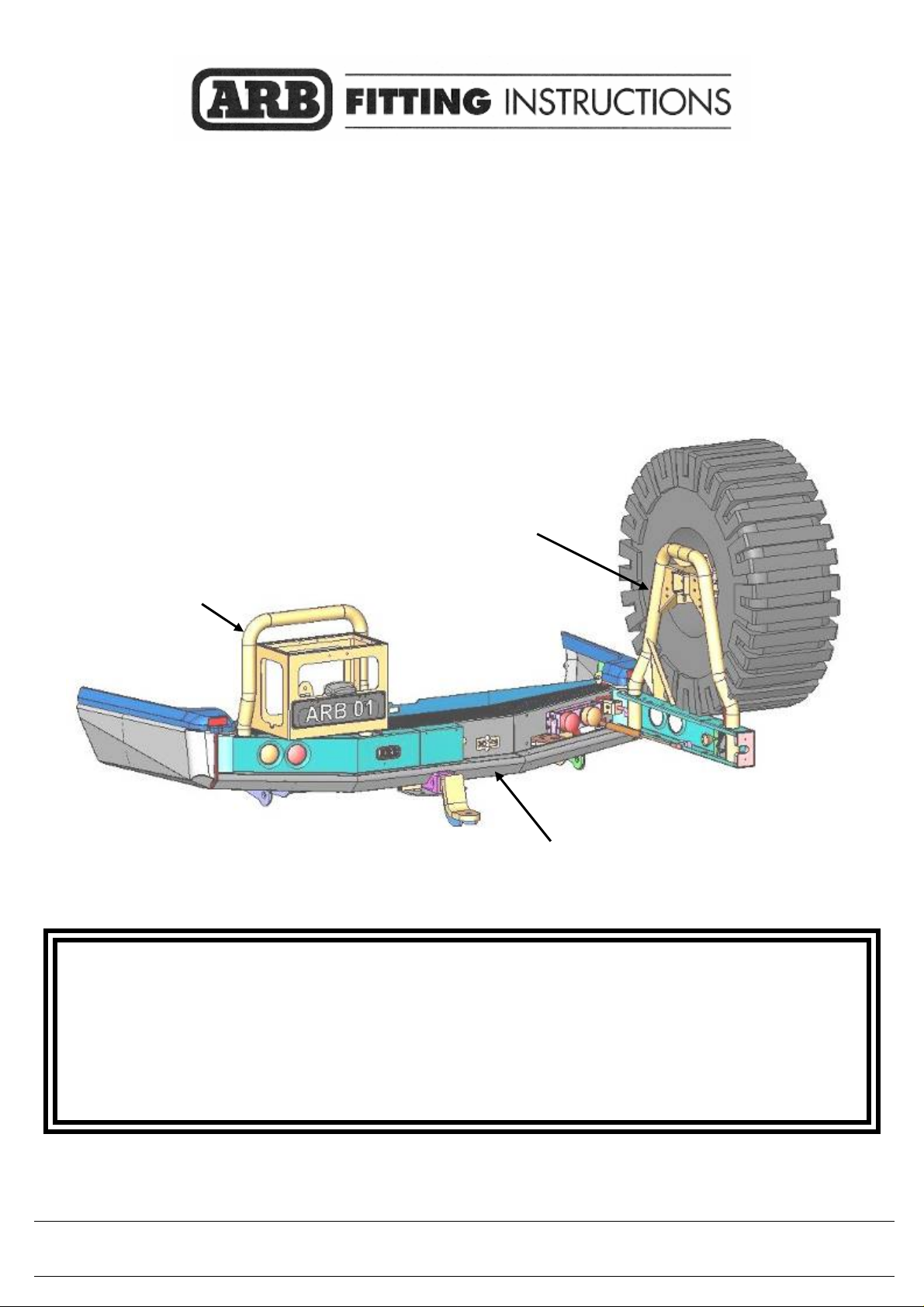
1. Compile components as shown.
- Light assembly (LHS shown)
- Light cover
- 6 x M6 x 16mm bolts
- 6 x M6 flange nuts
- 2x M6 cage nuts
- 6 washers to suit M6
2. Fit cage nuts to light cover as shown.
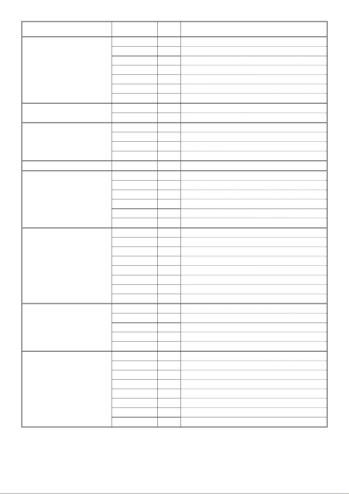
Outside of car
When fitting light assemblies to bar,
orange (indicator) lights must be to
the outside as shown. The flange on
the bracket should also be at the top.
Orange light
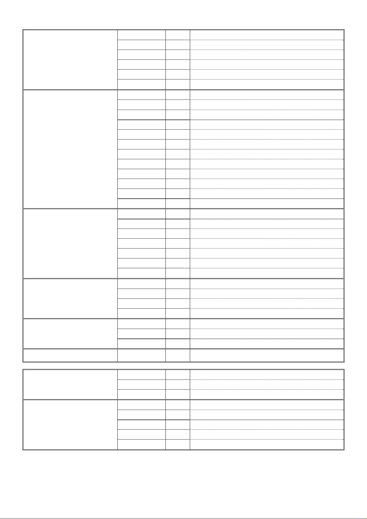
3. Feed looms through large hole in bar.
4. Fit light assemblies using M6 hardware.
Finger tighten only.
5. Repeat steps 1 to 3 for RHS assembly.
08-10-09 Page 4 of 19
3783146
Page 5
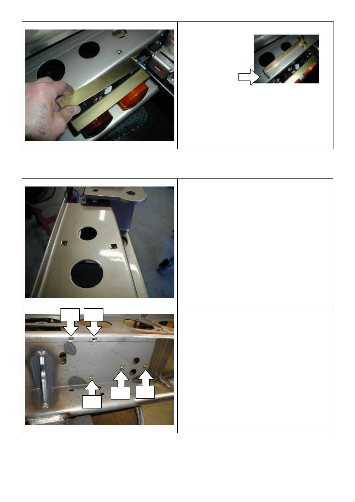
FITTING CAGE NUTS TO BAR
6. Fit M6 cage nuts
to light mount cover
bracket as shown.
7. Using M6 x 16 bolts and flat washers, fit
cover bracket to light mount.
8. Tighten only cover bracket bolts securely.
9. Fit M6 cage nuts (9 total) in square holes in
top of bar as shown.
M6
M6
10. Fit M6 cage nuts (6 total) and M8 cage nuts
M8
M6
08-10-09 Page 5 of 19
M8
(4 total) to front of bar. (RHS shown)
3783146
Page 6
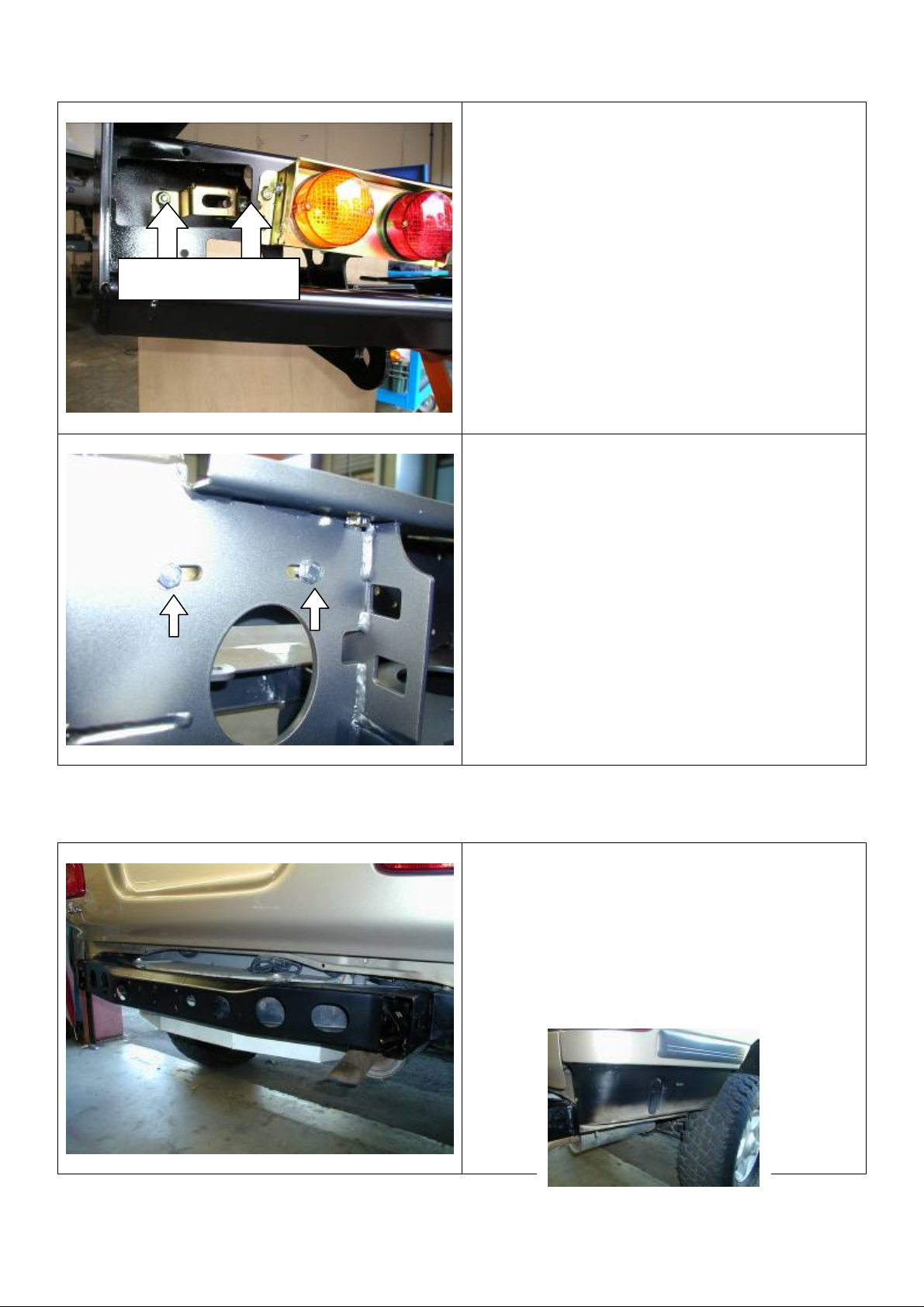
FITTING LOCKING PIN BRACKETS TO BAR
Flange nuts this side
11. Fit locking pin brackets using two M8 x 25
bolts, flat washers and flange nuts. Finger
tighten only.
Fit bolts through from rear of rear bar so
that the flange nuts are on the same side
as the bracket as the photo shows.
(Viewed from front of bar LHS.)
REMOVING BUMPER
12. M8 bolts must fit in rear of bar for ease of
adjustment later on.
(Viewed from rear of bar LHS.)
13. To fit Rear Bar to vehicle, remove bumper
bar, mud flap and tow bar (if fitted) from
vehicle.
OPTIONAL
Paint lower rear quarter panel satin black.
08-10-09 Page 6 of 19
3783146
Page 7

FITTING LOOM TO VEHICLE
14. Fit loom inside rear cross member of
vehicle chassis.
The plug for connecting the loom to the
vehicle must be on the RHS of the
vehicle.
Trailer plug wires
LHS
Tail light
connector
with
yellow
RHS
Tail light
connector
with green
wire
15. Exit tail light wires and trailer plug wires as
shown.
The tail light connectors with the
GREEN wire must be on the RHS of the
vehicle.
The tail light connectors with the
YELLOW wire must be on the LHS of the
vehicle.
16. The loom is fitted with wiring for a number
plate light.
If a jerry can carrier is to be fitted the
number plate and light should be fitted to it.
The wire for the number plate light must be
on the same side of the vehicle as the jerry
can carrier.
Number plate
light wires
08-10-09 Page 7 of 19
If a wheel carrier is to be fitted without a
jerry can carrier the wire for the number
plate light should be on the same side of
the vehicle as the wheel carrier.
3783146
Page 8

17. Make sure when plug is connected to
vehicle that wire is cable tied well clear of
muffler and exhaust components that may
melt it.
FITTING REAR BAR TO VEHICLE
18. If a wheel carrier or jerry can carrier is not
to be fitted a cover panel must be fitted.
If cover panels are to be fitted
they must be fitted to the bar
before it is fitted to the vehicle.
Refer to fitting instructions supplied in
cover panel fitting kit for fitment of
cover panel.
19. Fit 8mm cage nuts to wing brace nut
plate and insert into LHS of vehicle and
align with rear holes in side of chassis
08-10-09 Page 8 of 19
3783146
Page 9

20. With the help of a friend to hold the
previously fitted nut plate in the correct
position, fit the LHS end surround brace to
the side of the chassis rail using M8 x
35mm bolts, spring washer and flat
washer., finger tighten only.
21. Whilst working on the LHS, fit M12 x 1.75
caged nuts into side plates, and fit plate
as to press wing brace nut plate arm
against the inside of the chassis rail to
stop any rattling when the rear bar is fitted
to vehicle.
NB FIT CAGE NUTS TO SIDE
PLATES SO PLATES ARE
HANDED.
22. Fit M12 x 1.75 cage nuts to chassis side
plates and insert into end of chassis rails.
NOTE:
After bar is fitted and bolts are tightened
in these chassis side plates, the handles
must be bend over so that struts are not
damaged when wheel carriers or jerry can
carriers are closed.
08-10-09 Page 9 of 19
3783146
Page 10

23.
Fit 2 x M12 x 1.75 cage nuts into plate and
insert into inside RHS chassis rail and
align with underside of chassis holes.
Bend rear handle of nut plate to enable
24.
plate to fit flat on the inside of chassis rail.
25. On RHS of vehicle remove exhaust
hanger bracket from vehicle and remove
rubber isolater body from muffler for ease
of fitment later.
26. Using M8 x 35mm bolts, spring washers
and flat washers, secure side surround
brace to rear holes in side of chassis
rails.
27. Refit rubber isolater body back to muffler
and to the side surround brace.
FINGER TIGHTEN ONLY
28. Fit M12 x 1.75 cage nut into rear cross
member nut plate and fit to both sides of
rear cross member.
08-10-09 Page 10 of 19
PHOTO IS LHS OF VEHICLE
3783146
Page 11

29. Slide bar onto rear of chassis leaving
enough room to plug main loom into tail
light assemblies on either side of vehicle.
30. When this is done push bar onto chassis
until centre mount of bar is flush up against
chassis cross member.
31. Fit two M12 x 40 x 1.25 bolts, spring
washers and flat washers as shown into
centre mounting bracket.
(Finger tighten only.)
32. Fit 3 x M12 x 40mm x 1.25 (fine thread)
bolts, spring washers and large gold
colored flat washers to underside of
chassis rails to LHS of vehicle
(Finger tighten only.)
08-10-09 Page 11 of 19
M12 X 1.25 X 50 BOLTS
( FINE THREAD )
3783146
Page 12

To the RHS of the vehicle, fit 2 x M12 x 1.75 x
50 ( coarse thread ) bolts, spring washer and
flat large gold coloured washer to the most
forward hole. To the rear hole, fit 1 x M12 x
1.25 x50 bolt, spring washer and flat large gold
coloured washer
M12 X 1.75 X 50 BOLTS
M12 X 50 X 1.25 BOLT
33. Fit two M12 x 40 x 1.75 bolts, large gold
coloured flat washers and spring washers
into captive nut plates (installed previously
step17) on each side of vehicle.
(Finger tighten only)
Align nut plates using handle that protrudes
through cut out in rear of bar.
34. Before tightening any bolts you must fit the
8mm packers in between the rear bar and
the vehicle chassis. The double cut out
packers to the rear of the bar, and the
single cut out packers to the front of the
bar. When these packers are fitted, tighten
all bolts firmly.
ARROWS INDICATE WHERE
PACKERS ARE TO BE FITTED
08-10-09 Page 12 of 19
3783146
Page 13

35.
. The single cut out packers to the front of
the bar. (As viewed from front of vehicle )
When these packers are fitted, tighten all
bolts firmly.
Bend handle over
36.
Bend over handles of nut
plates so that struts are
not destroyed when wheel
carriers or jerry can carriers
are closed.
AT THIS STAGE JERRY CAN CARRIERS OR WHEEL CARRIERS MUST BE FITTED.
TO FIT JERRY CAN CARRIERS AND WHEEL CARRIERS, REFER TO FITTING
INSTRUCTIONS SUPPLIED IN FITTING KITS WITH JERRY CAN CARRIERS OR WHEEL
CARRIERS.
IF A JERRY CAN CARRIER OR WHEEL CARRIER IS NOT TO BE FITTED, THE COVER
PANEL SHOULD BE ALREADY FITTED. (REFER TO STEP 16.)
08-10-09 Page 13 of 19
3783146
Page 14

FITTING CENTRE COVER PANEL
Black nylon washer
37. Compile the components as shown
- Centre cover panel
- 2 x M6 cage nuts
- 2 x M6 x 25 socket head cap screw
stainless steel
- 2 x M6 x 25 bolts
- 4 x 6mm flat washers
- 2 x black nylon packers
- 2 x 8mm thick gold zinc spacers
- 4 x 6mm spring washers
38. Place M6 cage nuts into lower section of
centre cover panel.
39. Fit two M6 x 25 stainless steel socket
head cap screws, flat washers and spring
washers through top flange inside cover
panel as shown.
40. Place black nylon spacers on screws on
outside of centre cover panel flange and
attach to captive nuts in rear bar.
M6 cage nuts
(Finger tighten only.)
41. Place 8mm spacer between underside of
centre cover panel and rear bar.
08-10-09 Page 14 of 19
3783146
Page 15

42. From underneath rear bar pass two M6 x
25 bolts, flat washers and spring washers
through the aligned parts and finger
tighten.
M6 x 25 bolt and flat washer
FITTING END SURROUNDS TO REAR BAR
Top RHS
43.
Align faces of centre cover panel with
wheel carrier, jerry can carrier or cover
panel and tighten securely.
44. The surrounds are attached to rear bar
using three M8 x 35 bolts, flat washers
and flange nuts per side.
45. Place bolts and flat washers through the
top two holes of the rear bar end plate as
shown.
M8 flange nut
M8 x 35 bolt
and washer
46. Fit 8mm spacer to bolts, then fit end
surround and secure finger tight with M8
flange nuts.
8mm spacer
47. Fit the lower bolt with washer, spacer and
nut in the same sequence as the upper
two.
(Finger tighten only)
08-10-09 Page 15 of 19
3783146
Page 16

48. Using M8 x 20 bolts, flat washers and
flange nuts secure end surrounds to braces
finger tight. (RHS shown.)
VIEWED FROM RHS OF VEHICLE.
49. Before tightening bolts fit urethane vertical
trim between end plate and end surround.
50. Adjust trim to fit snugly around the rear bar
and the end surround.
51. Align top face of end surround parallel with
body of vehicle.
52. Starting in the top corner of the end
surround and working backwards tighten all
bolts.
A second person may be required to help
keep the vertical trim fitting snugly and to
ensure the end surround remains parallel
to the body.
08-10-09 Page 16 of 19
3783146
Page 17

53. Fit reflector to end of buffer.
54. Fit urethane buffer to top of end surround
using M6 nyloc nuts and large black flat
washers.
When fitting washers to studs under end
surround smear flat washers with grease to
hold them in place as shown below.
Reflector
FITTING TOP INFILL PLATE AND ALUMINIUM STEP PLATE
55. Using M6 button head cap screws fit top
infill plate.
56. To fit rubber sealing strip to underside of
aluminium step plate, lay strip on the
underside of step plate and place so over
hang is even on both ends. Using scissors,
cut darts up to the bulb end of the rubber
strip, so the strip can follow the front profile
of the aluminium step plate.
08-10-09 Page 17 of 19
3783146
Page 18

57. Carefully remove backing tape on the
rubber strip and fit to step plate working
from the centre outwards. Make sure
rubber strip hugs the front edge of the
aluminium step plate.
Using M6 button head cap screws fit
58.
aluminium step plate
08-10-09 Page 18 of 19
3783146
Page 19

FITTING TRAILER PLUG AND GOOSENECK
59. Fit trailer plug to recess using M5 pan head
screws as shown by arrows.
For aesthetics and protection of the plug it
is recommended that a flat type plug is
fitted.
To fit alternate plugs an adaptor bracket
(part number 5700090) is available. This is
not supplied as standard with the rear bar
kit.
60.
Fit gooseneck with pull pin and spring clip
as shown.
08-10-09 Page 19 of 19
3783146
 Loading...